Article

The Effect of Heat Treatment and Cold Forging on the Mechanical Properties of SCr420 Low-Alloy Steel

1
Hyundai Steel R&D Center, Dangjin 1480, Republic of Korea
2
Department of Materials Science and Engineering, Inha University, Incheon 22212, Republic of Korea
3
Department of Advanced Materials Processing and Engineering, Inha Manufacturing School, Incheon 21999, Republic of Korea
*
Author to whom correspondence should be addressed.
Metals 2025, 15(3), 336; https://doi.org/10.3390/met15030336
Submission received: 21 February 2025 / Revised: 17 March 2025 / Accepted: 18 March 2025 / Published: 19 March 2025

Abstract

:
This study developed a new heat treatment method, normalizing and stress relief (NSR), to increase productivity compared to spheroidizing annealing (SA). The influence of different microstructures resulting from these heat treatments was investigated in cold-forged steel. Despite a shorter heat treatment time, the mechanical properties of the NSR alloy were found to be similar to those of the SA alloy. The factors influencing the mechanical properties of the experimental alloys were analyzed using the Hall–Petch equation, and the predicted values closely matched the measured strength of hyper-eutectoid steels. The primary factors affecting mechanical properties were microstructure and dislocation density. In the case of the SA alloy, the microstructure was associated with lower strength due to the spherical cementite structure. In contrast, the NSR alloy had lower strength because of a reduced dislocation density. This was achieved via stress-relief heat treatment below the A1 temperature after phase transformation. Based on the mechanical properties, cold forging simulations showed that the effective stress during cold forging of the NSR alloy was similar to that of the SA alloy.

1. Introduction

In response to global warming, the Paris Agreement came into effect in 2016 to keep temperature increases to well below 2 °C above pre-industrial levels. In response, major countries around the world are introducing carbon border taxes and adopting net-zero policies, hoping for the sum of carbon savings and emissions to become zero by 2050 [1]. As a result, the automotive industry is making various attempts to comply with greenhouse gas reduction policies [2,3,4]. In particular, in the field of automotive drive components, forging and heat treatment processes are being changed to improve material recovery and to reduce carbon emissions. Forging is the process of manufacturing automotive parts by applying heat and pressure to a metal to plastically deform it. Depending on the temperature, forging is categorized into hot forging and cold forging [5,6]. Hot forging heats the workpiece above its recrystallization temperature, resulting in excellent formability and productivity. However, its disadvantages include thermal cracking and poor dimensional accuracy and surface quality [7].
On the other hand, cold forging is a forging process that takes place at room temperature, so the dimensional accuracy of the alloy is very good. However, the material must be heat-treated before forging to remain ductile [8,9,10]. In particular, the cold forging process is carried out after forming a ductile microstructure because many large deformations occur at room temperature during forging.
The heat treatment patterns for optimizing cold forging performance have been carried out in various ways, and the representative patterns are shown in Figure 1. The patterns (a) and (b) are primarily applied in the industry and involve heat treatment at temperatures near A1 for extended periods. In the case of (c), the material is heat-treated above the austenitizing(A3) temperature, and due to phase transformation during the cooling process, the hardness increases, resulting in reduced cold forging efficiency. Pattern (d) promotes spheroidization by repeatedly heating and cooling, cycling through temperatures just above and below A1. While this method accelerates spheroidization, it is not commonly adopted in the industry due to the difficulty in temperature control. Therefore, the spheroidizing annealing patterns (a) and (b) are mainly applied in industry, but the productivity efficiency of forged products is not optimal due to the prolonged heat treatment, and a large amount of carbon is emitted [9,11,12].
Therefore, in this study, a new NSR heat treatment pattern is proposed to effectively reduce the heat treatment time while maintaining the same level of mechanical properties as the existing SA heat-treated materials, in order to secure productivity and contribute to environmental sustainability. NSR improves productivity by approximately 70% compared with the conventional SA heat treatment, which can significantly reduce manufacturing costs and carbon emissions. To confirm the effectiveness of an NSR heat treatment, SCr420 steel was selected as the test alloy, as it is widely used in automotive parts, and its microstructure analysis and mechanical properties were compared based on the used heat treatment method [13].
The Hall–Petch model was used to investigate why the mechanical properties of SA and NSR alloys are similar despite one having a reduced heat treatment time. The effective stresses resulting from cold forging during the SA and NSR heat treatments were also compared using AFDEX (V24R01), a finite element analysis software for plastic processing.

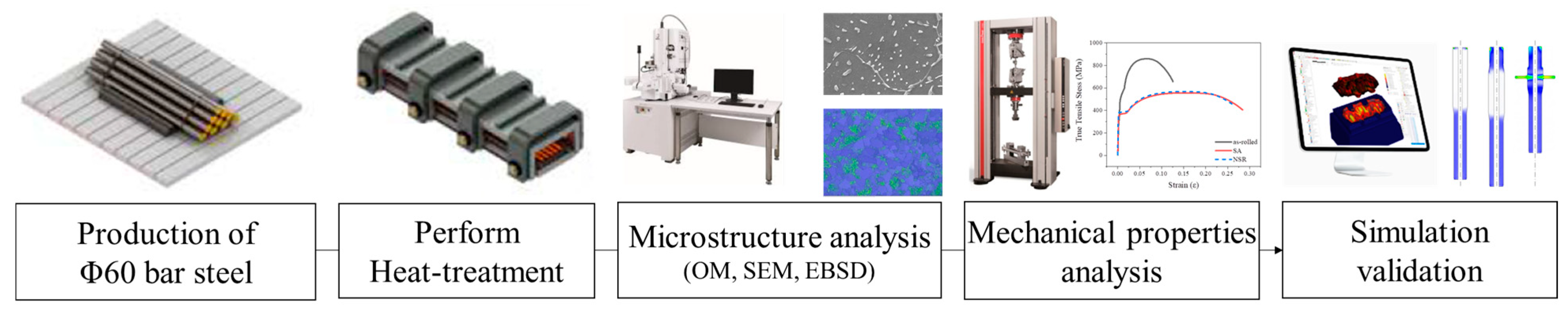
2. Materials and Methods

2.1. Characteristics of SCr420 Low-Alloy Steel

SCr420 low-alloy steel has excellent hardenability, providing superior strength and wear resistance after carburizing heat treatment. Due to these properties, the SCr420 grade is widely used in components that require high strength and wear resistance, such as automotive transmissions and gears. Additionally, SCr420 features a relatively low carbon content, making it easily deformable in the cold state, which makes it well-suited for cold forging processes and ideal for manufacturing components that require high-precision dimensional control [14].

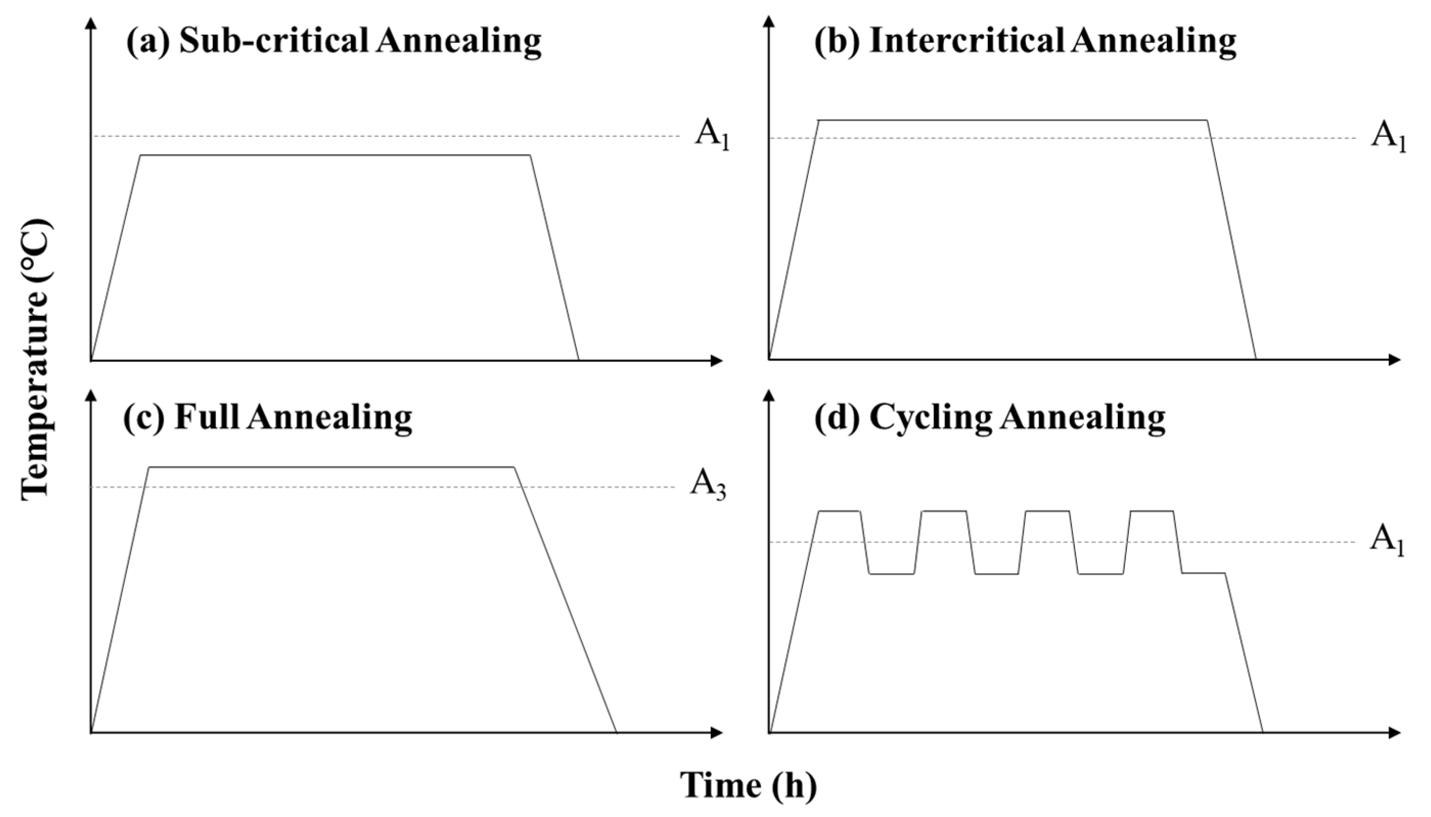
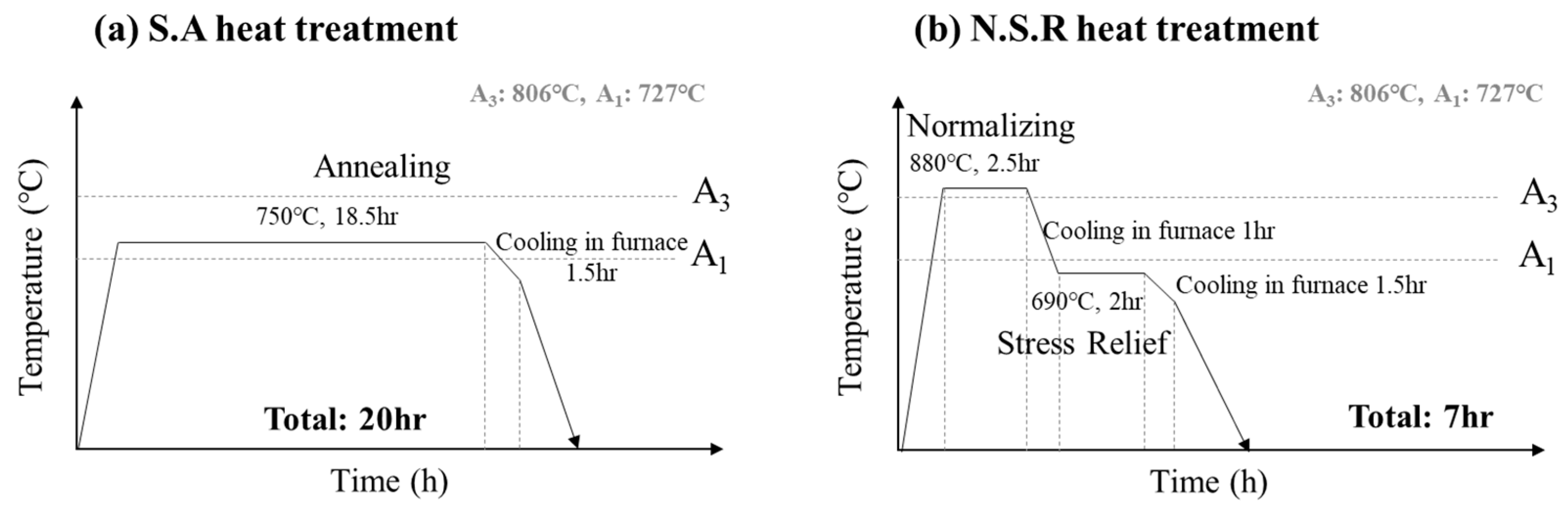
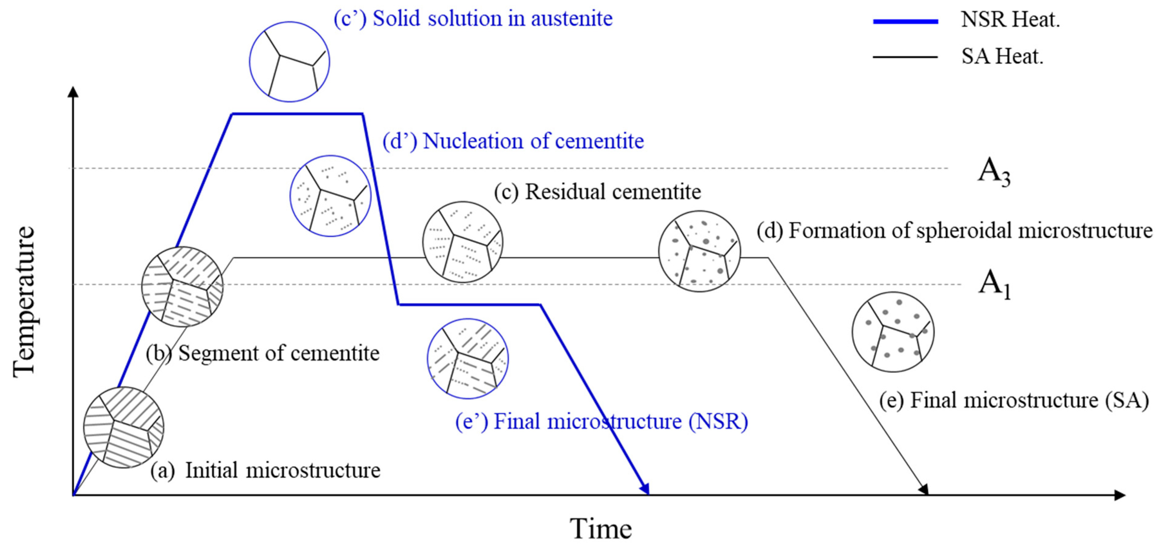
2.2. Development of the NSR Heat Treatment

In industry, spheroidizing annealing to achieve ductility in materials is typically carried out near the A1 temperature for a considerable amount of time before cooling [9,11,12,15,16]. This heat treatment experiences difficulty securing productivity and emits a lot of CO2 gas, so it needs to be improved from a long-term perspective. In this study, we developed a new heat treatment method (NSR) that can compensate for the shortcomings of spheroidizing annealing, and a schematic diagram of the heat treatment is shown in Figure 2.
NSR heat treatment is a heat treatment method that applies a combination of normalizing and stress relief heat treatments, thus shortening the heat treatment time to 7 h by controlling the heat treatment temperature and cooling rate. In order to improve the strength and microstructure homogenization of the alloy, cooling is performed below the A1 temperature after maintaining the austenite region above the A3 temperature for a certain duration. The alloy is then heat-treated and annealed below the A1 temperature to minimize the residual stresses generated during the phase transformation from γ(austenite) to α(ferrite) + θ(cementite).
In this study, SA and NSR heat treatments were performed on SCr420 material with the composition shown in Table 1. The SCr420 material utilized in this study is Φ60 bar steel from Hyundai Steel (Incheon, Republic of Korea).

2.3. Microstructures and Mechanical Properties

Experiments and analyses were conducted in the order shown in Figure 3. To analyze the microstructure of the experimental alloys before and after heat treatment, vertical cut surfaces of the Φ60 rolled bar and heat-treated material were mechanically polished with silicon carbide paper (#100~#2000) and diamond suspension at the 1 μm level and etched with a 3% solution of Nital. Microstructural analysis measurements were analyzed using OM (Olympus Gx51, Olympus, Center Valley, PA, USA) and SEM-EDS (JEOL, Tokyo, Japan, 7100F) microscopes. The ferrite fraction was measured according to ASTM E562 [17], and the remaining volume fractions, other than the measured ferrite fraction, were considered pearlite.
The cementite spacing of the experimental alloys was measured by applying the mean free path (MFP) method. For a quantitative analysis of MFP, at least 10 SEM photographs were taken at ×20,000 magnification for each condition. Based on this, the mean random spacing obtained was divided by 2 to obtain the mean true spacing, as shown in Equation (1) [18].
S r = 3.14   ·   D 2 n
where Sr is the average distance between cementite lamella, D is the diameter of the measurement area, and n is the number of cementites measured in that area. Grain size and dislocation density were measured using an EBSD (Oxford Symmetry) mounted on an FE-SEM. Grain size was measured at a magnification of ×500, a step size of 0.2 μm, a tilt of 0%, and an accelerating voltage of 20 kV. Dislocation density was measured at ×1000 magnification, a step size of 0.2 μm, a slope of 80%, and an acceleration voltage of 20 kV.
To evaluate the mechanical properties of the SA and NSR alloys, samples were taken at the 1/4 point of the cross-section of the Φ60 bar and evaluated with tensile and compression tests at room temperature. The tensile specimens were evaluated on a tensile testing machine (Zwick/Roell, Ulm, Germany, Z250) using a proportional test specimen, KS 14A (diameter 6 mm, marking distance 30 mm). The tensile test was performed at 0.009 mm/s until it yielded and at 0.241 mm/s during tension.
The compression test was performed using a compression tester (Zwick/Roell, Z600) with a 15 mm compression specimen of Ø10. The compression test was performed at a speed of 3.3 mm/s to compress the specimen to 60% of its cross-sectional area.

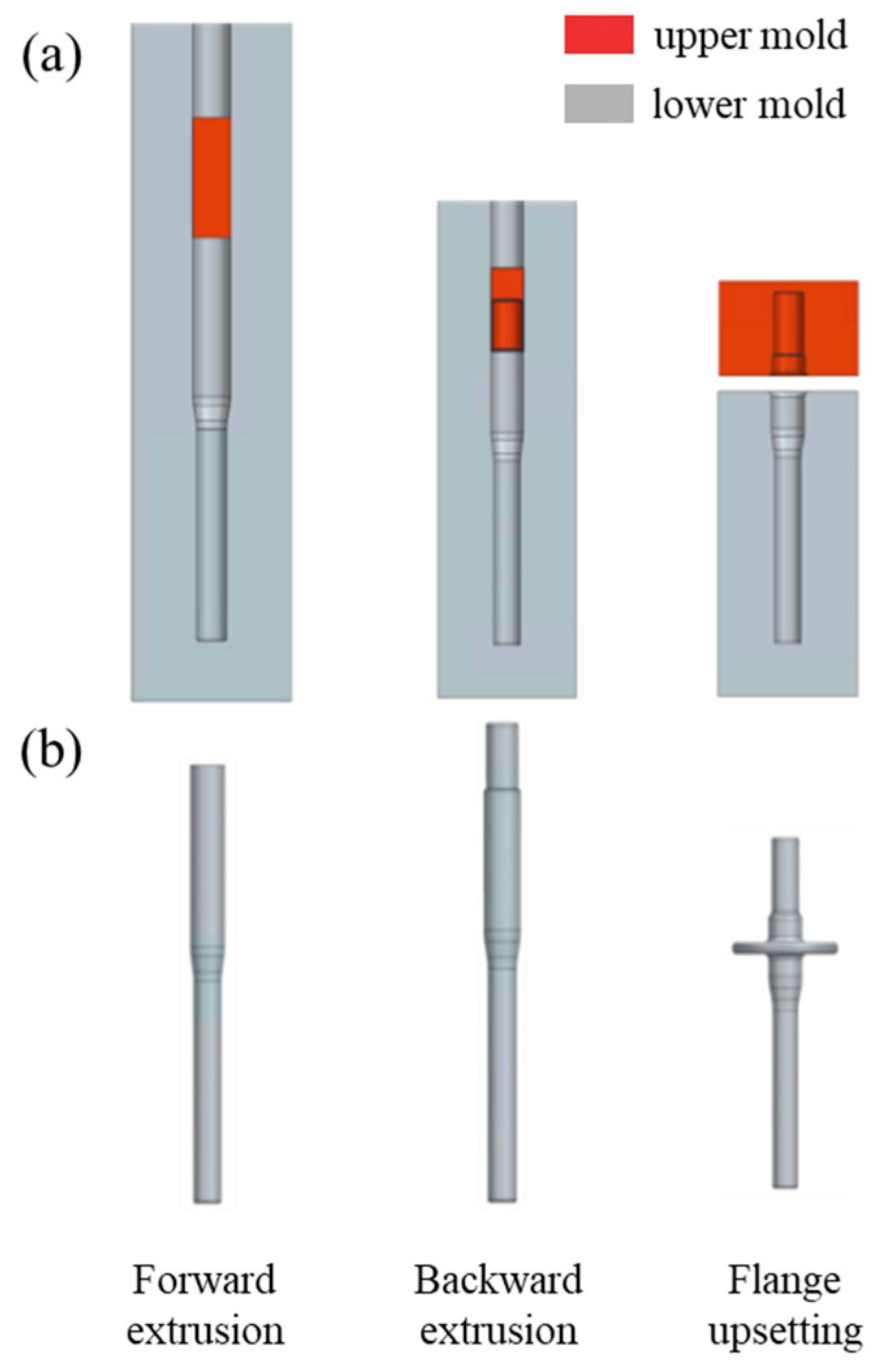
2.4. Finite Element Analysis of Cold Forging Formability

In order to validate the cold forging process of an NSR alloy, a commercial forging analysis was conducted on the input shaft, an automotive drive part. The input shaft cold forging process consists of three processes: forward extrusion, backward extrusion, and flange upsetting. The molds and models for each process are shown in Figure 4.
The finite element model of the input shaft was made of SCr420 Φ60 bar steel cut into 300 mm lengths, and the molds of each process were modeled at a 1:1 scale and meshed with Tetrahedral Brick Element. AFDEX, a commercial forging finite element analysis software, was then used to analyze formation during each process. The stress–strain curves from the cold forgeability evaluation of the SA and NSR alloys were based on the room temperature tensile test results. In addition, Young’s modulus, Poisson’s ratio, density, and the thermal expansion coefficient were calculated in JMatPro(Version 13), a thermodynamic simulation program, and are shown in Table 2.
To avoid direct friction between the mold and the workpiece during cold forging, a phosphate coating treatment was applied on the workpiece, the Coulomb friction coefficient between the forging mold and the workpiece was set at 0.1, and an elastic deformation analysis was performed [19].

3. Results and Discussion

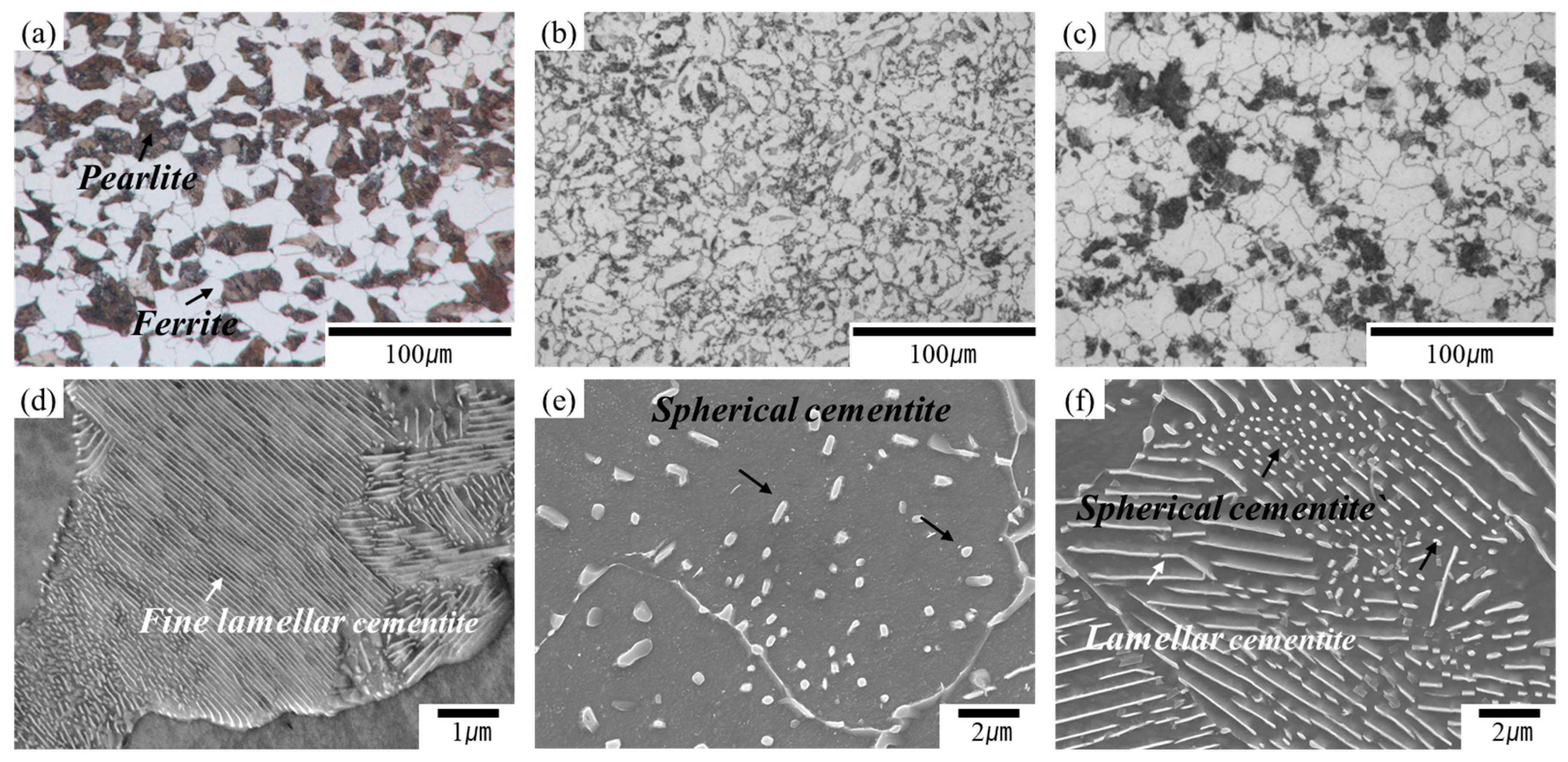
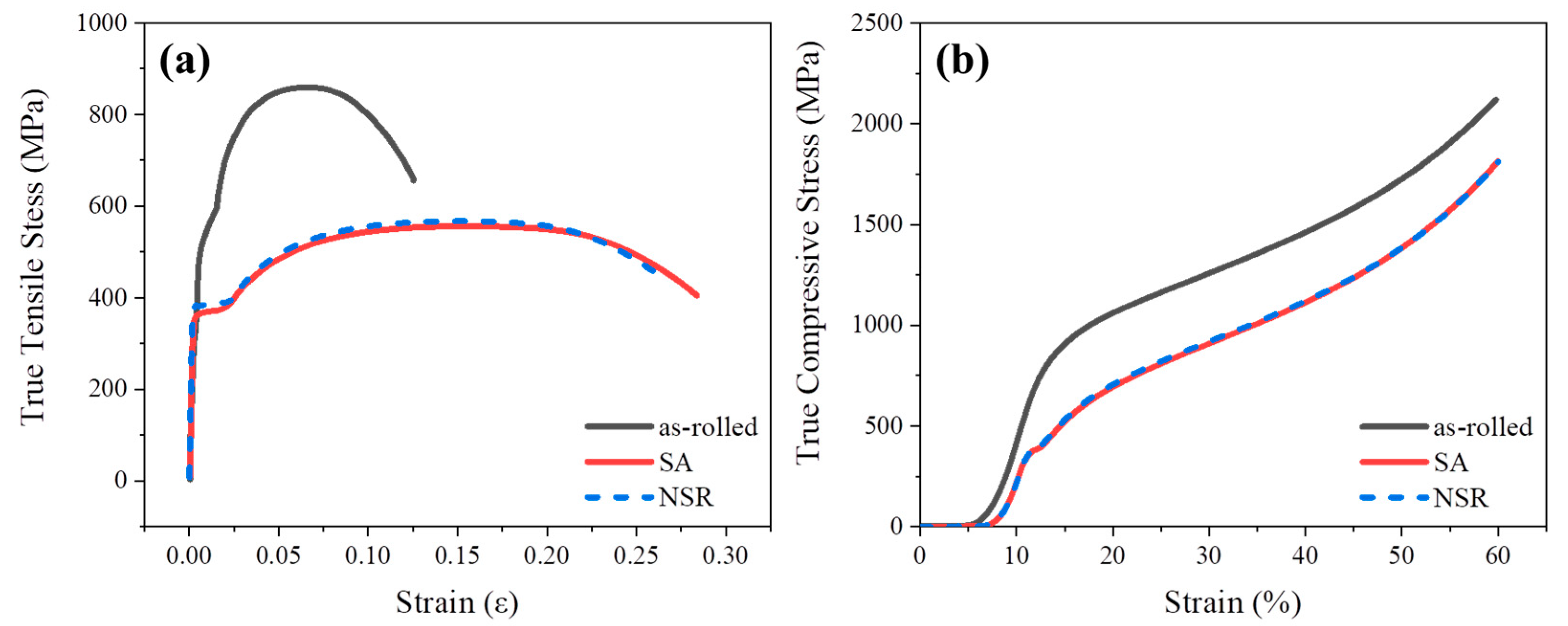
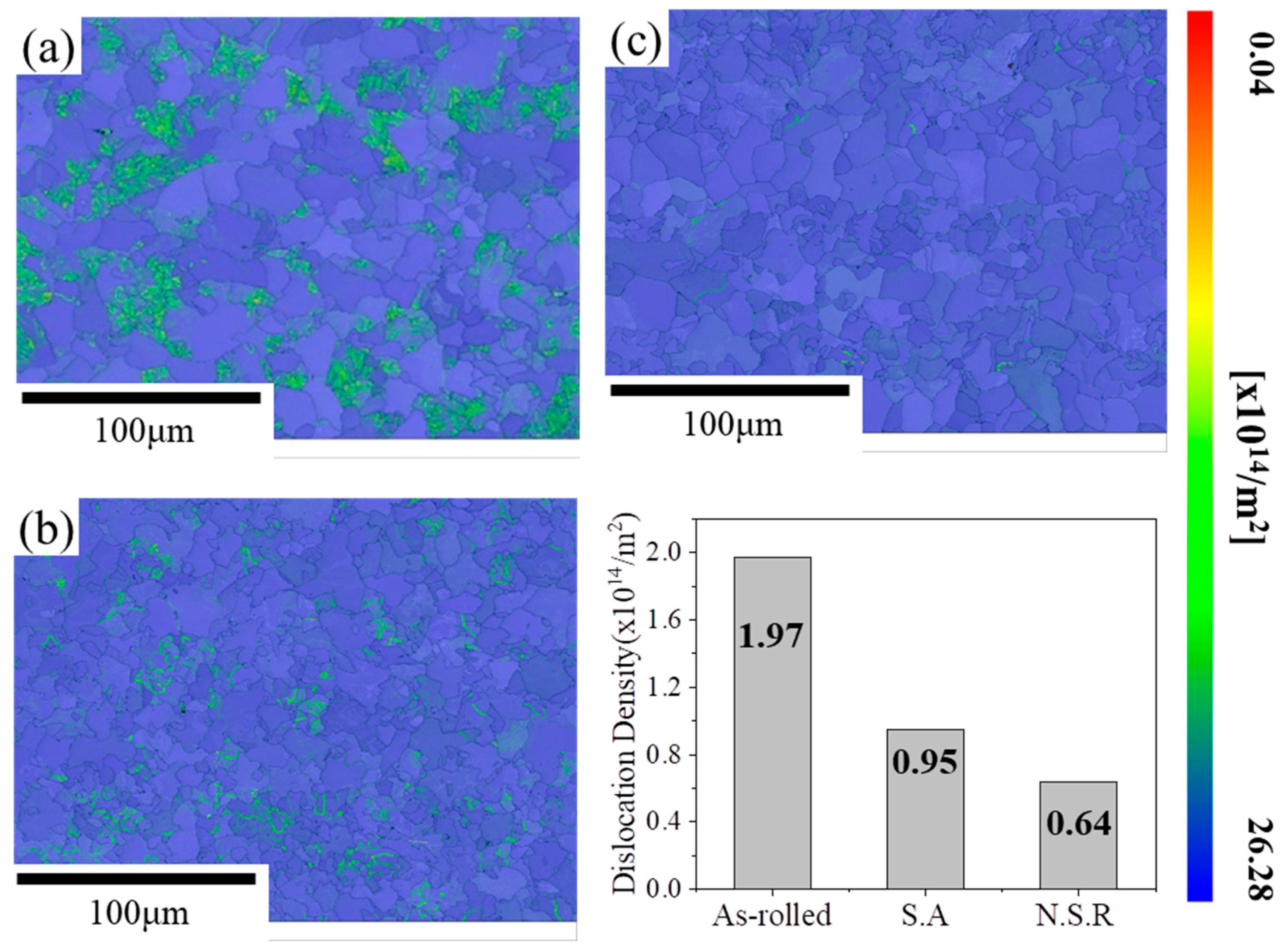
3.1. Microstructures and Mechanical Properties

Figure 5 shows microstructure observations of the as-rolled and heat-treated steels. Figure 5a shows the microstructure of the as-rolled SCr420 steel, which has a mixed ferrite and pearlite microstructure. In addition, Figure 5d shows a micrograph of pearlite at ×30,000 magnification, confirming the fine lamella structure of cementite.
The SA alloy exhibited a typical spherical cementite microstructure, as shown in Figure 5b,f [20]. As shown in the schematic diagram in Figure 6, SA heat treatment causes the lamella cementite in the pearlite to segment above the initial A1 temperature. Then, with prolonged heat treatment, some of the carbon dissolves and residual cementite remains. In the subsequent heat treatment and cooling stages, the undissolved residual cementite acts as a nucleation site for the growth of spherical cementite [21,22]. On the other hand, the microstructure of NSR heat-treated alloy involves a mix of lamellar and spherical cementite, as shown in Figure 5f because the cementite dissolved at A3 and above grows into spherical cementite as it cools to below the A1 temperature and the growth of cementite, when maintained at temperatures below A1, results in a mixed lamellar and spherical microstructure.
The ferrite fraction of the experimental alloys was measured based on the as-rolled and heat treatment conditions. The ferrite fraction was measured to be 55% for the as-rolled condition, 80% for SA, and 74% for NSR. The main reason for the difference in ferrite fractions between the as-rolled and heat-treated methods is the cooling rate and start temperature.
Slower cooling rates increase the fraction of ferrite, while faster cooling rates increase the fraction of pearlite due to the shorter distance that the dissolved carbon atoms in the austenite can travel [22]. In other words, the accumulation of carbon at the austenite/ferrite interface makes the formation of pearlite at high temperatures easier and the interlamellar distance of cementite smaller. In general, the cooling rate of Φ60 bar steel after rolling is measured to be about 0.5~1 °C/s for air cooling and about 0.1 °C/s for furnace cooling. Therefore, the pearlite fraction of the as-rolled material with the fastest cooling rate is the highest. In addition, when the cooling start temperature is lower than A3, as in SA heat treatment, austenite and cementite coexist in the same region, so the shape of cementite is affected by the heat treatment temperature [15,21]. Therefore, even if the cooling rate of SA alloy and NSR alloy is the same, at 0.1 °C, their ferrite fractions are different. The tensile and compressive strengths of the SA and NSR alloys are shown in Figure 7 and Table 3, respectively.
The tensile test results showed that the yield strength of the as-rolled material was 565 MPa and the ultimate tensile strength was 842 MPa. In comparison, the yield strength of the SA alloy was 377 MPa, and the tensile strength was 556 MPa. Finally, the yield strength of the NSR alloy was measured at 382 MPa and the tensile strength was 567 MPa.
In addition, the compressive strength of the as-rolled material at 60% cross-sectional area compression was measured to be 2119 MPa, while the compressive strengths of the SA and NSR heat-treated alloys were 1810 MPa and 1815 MPa, respectively. Despite the different heat treatment methods, their tensile and compressive properties were found to be similar.

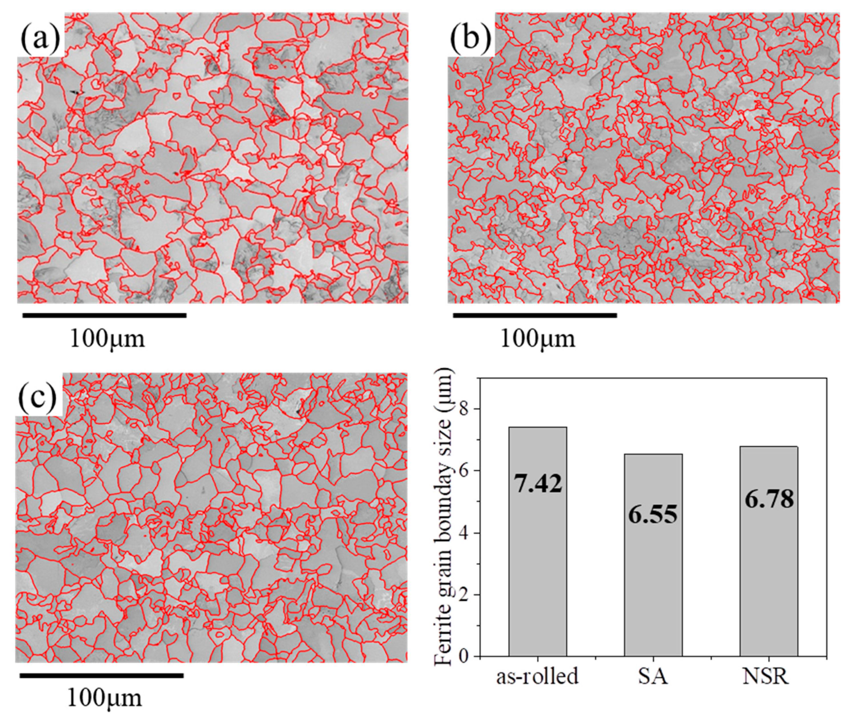
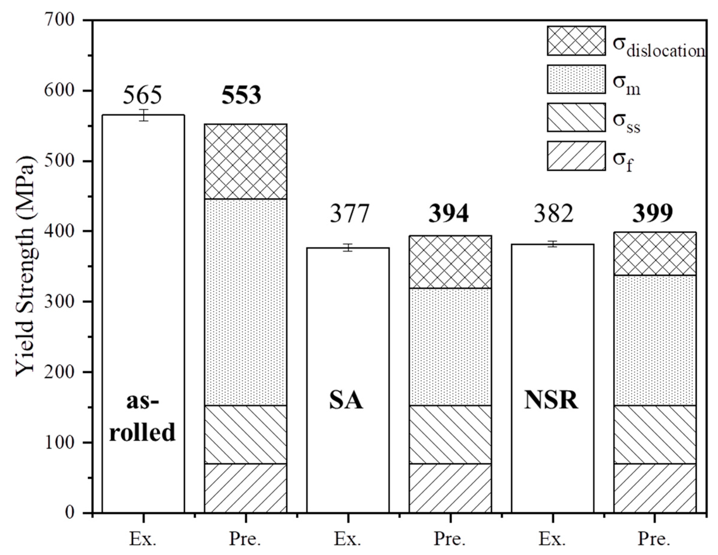
3.2. On the Strength Mechanisms

In general, the mechanical properties of pearlite steels can be described using the Hall–Petch relationship, as shown in Equation (2) [23].
σ = σ o + K y   λ 1 2
where σ is the yield strength, σo is the friction stress, Ky is the Hall–Petch constant, and λ is the interlamellar spacing of pearlitic steels. However, hypo-eutectoid steels are not well represented in Equation (2) because they have a dual-phase ferrite–pearlite structure. Therefore, various studies have attempted to quantify the strength of steels with dual phase ferrite–pearlite steels, as shown in Equation (3), including those by O’Donnelly, Reuben, and Baker [24].
σ = σ f + K y λ p 1 2
where σf is the friction stress of pure ferrite, Ky is the constant, λp is the mean ferrite slip distance in the composite, and λp is defined in Equation (4) [24].
λ p = V p S r T r + V a + d a
where Vp and Va are the pearlite and ferrite fractions, respectively; da is the ferrite grain size; Sr is the interlamellar spacing; and Tr is the mean cementite thickness, expressed in Equation (5) [25].
T r = 0.15   ·   C a r b o n w t %   ·   S r V p
Based on the above equations, this study expresses the yield strength of hypo-eutectoid steels as Equations (6) and (7) below.
σ m = K y [ V p S r T r + V a d a ] 1 2
σ y = σ f + Δ σ m + Δ σ s s + Δ σ d i s + Δ σ p a r t i c l e
where σf is the ferrite strength, Δσss is the solid solution hardening, Δσdis is the dislocation hardening, and Δσparticle is the precipitation hardening. However, the experimental alloys used in this study make a very low contribution to precipitate formation, so the Δσparticle effect was excluded.
Initially, σf was used as σf = 70 MPa for pure Fe [26]. However, as Ky is a material constant that varies with heat treatment conditions, experimental values were applied, and Ky was calculated from the yield zone slopes of the experimental alloys. As shown in Table 4, the Ky values for the experimental alloys were measured as follows: as-rolled material, 601 MPa/µm1/2; SA alloy, 411 MPa/µm1/2; and NSR alloy, 430 MPa/µm1/2. The as-rolled Ky values were within the typical range of 440 to 760 MPa/µm1/2 for ferrite–pearlite steels [27].
The SA and NSR Ky values were found to be similar to the Ky value (420 MPa/µm1/2) obtained from the spheroidizing heat treatment in a similar carbon range studied by L. Anand. This phenomenon of decreasing Ky value with a slower cooling rate is due to the transformation of the lamellar structure of cementite into a spheroidal form and its distribution within the grains [20,27]. Therefore, the Ky values of the SA and NSR alloys were lower than that of the as-rolled material.
The Sr of the experimental alloys was calculated using Equation (1) to obtain the average true spacing of cementite, and Tr was calculated based on Equation (5). Sr was measured to be 0.12 µm for the as-rolled material, 3.6 µm for the SA alloy, and 1.3 µm for the NSR alloy. Tr was measured to be 0.01 µm for the as-rolled material, 0.43 µm for the SA alloy, and 0.19 µm for the NSR alloy.
Average grain size has a significant influence on the strength of metallic materials because high-angle grain boundaries (HAGBs) inhibit the movement of dislocations [28,29]. da is the result of using an EBSD, and the average HAGB sizes were measured as 7.42 µm for the as-rolled material, 6.55 µm for the SA alloy, and 6.75 µm for the NSR alloy, as shown in Figure 8.
The strength of Δσm, based on grain size and the cementite parameters, was measured to be 293 MPa for the as-rolled material, 167 MPa for the SA alloy, and 185 MPa for the NSR alloy.
The strengthening mechanism for the chemical component can be explained as shown in Equation (8) below.
Δ σ s s = 47 S i + 30 M n + 31 C r
K.K. Ray reported that Mn and Si increase by 30 and 47 MPa per wt%, respectively [30]. Gutierrez also reported that Cr increases by 11 and 31 MPa per wt% [31].
Thus, the effect of solid solution strengthening based on composition was calculated to be 82.6 MPa. Another strengthening mechanism, dislocation strengthening, is expressed in Taylor’s equation, Equation (9) [29].
Δ σ d i s = α G b p
where α is the constant (0.38), G is the shear modulus (81 GPa), b is the Burgers vector (2.48 A), and p is the dislocation density [20,32,33].
The dislocation density of the experimental alloys was measured using Geometrically Necessary Dislocation (GND) density maps, as shown in Figure 9, and the dislocation densities were measured as follows: as-rolled material, 1.97 × 1014 cm2; SA alloy, 0.95 × 1014 cm2; and NSR alloy, 0.64 × 1014 cm2. Δσdis was calculated to be 107 MPa for the as-rolled material, 74 MPa for the SA alloy, and 61 MPa for the NSR alloy.
The sums of the predicted and experimentally measured values for each strengthening mechanism are shown in Figure 10.
The yield strength was predicted based on the parameters of the heat treatment process, and the predicted total strength was measured to be 553 MPa for the as-rolled material, 394 MPa for the SA alloy, and 399 MPa for the NSR alloy. These values are similar to the experimentally measured values, with a deviation of about △17 MPa. The difference between the measured and predicted yield strengths for the SA and NSR alloys was the same, at △5 MPa, indicating that the predicted values for each parameter affecting the yield strength were calculated correctly.
The difference in strength between the SA and NSR alloys was △18 MPa, depending on the microstructure variables. However, the reason that the NSR alloys exhibit similar strengths to the SA materials is due to the reduction in dislocation density. Compared with the as-rolled material, the dislocation density of the SA and NSR alloys was reduced by 52% and 68%, respectively. This resulted in a 13 MPa reduction in the dislocation-induced strengthening effect of the NSR alloy compared with that of the SA alloy.
In general, when steel passes through the A1 eutectoid temperature, a phase transformation dislocation is formed during the γ (austenite) → α (ferrite) + θ (cementite) phase transformation.
In the case of the SA alloy, as shown in Figure 2a, heat treatment above the A1 temperature results in the formation of austenite and spherical cementite, and the dislocations disappear. However, dislocations are generated by the newly grown pearlite during cooling [15,21]. On the other hand, in the case of the NSR alloy, stress relief heat treatment is performed below the A1 temperature after the phase transformation is completed, so the dislocation strengthening effect is reduced as the dislocations disappear.
Figure 11 shows the microstructure and GND density of the as-rolled material at a high magnification. The dislocation density is low in the ferrite region but high in the pearlite region. These results demonstrate that dislocations form as a result of phase transformation.

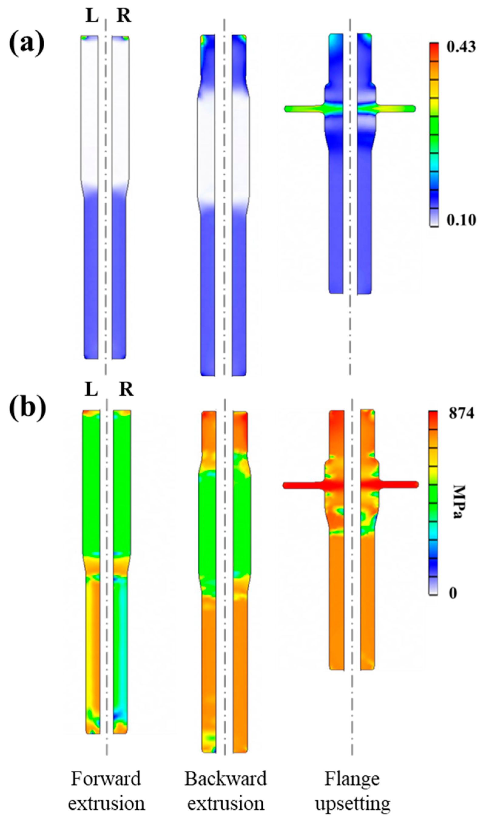
3.3. Results of Cold Forging Formability Analysis

The purpose of the effective strain and stress analysis was to compare the influence of the mold during the continuous production of automotive parts based on the heat treatment method. Figure 12 shows the results of analyzing the cold forging process of the input shaft using the mechanical properties of the experimental alloys when the SA and NSR heat treatments are applied, which include (a) effective strain and (b) effective stress. Both the SA and NSR alloys exhibited similar strain rates in the flange upsetting process with the highest compression ratio.
In addition, the maximum effective stress at the flange was 874 MPa for both the SA and NSR alloys, with no significant difference observed in the extrusion process. Therefore, the maximum stress of the NSR alloy during the forging process was confirmed to be similar to that of the SA alloy.
The similarity in effective stress and effective strain, despite the differences in the microstructures of SA and NSR, can be explained as follows: when NSR is applied to the SCr420 steel grade, the heat treatment time is reduced compared to SA, yet it demonstrates similar tensile and compressive strengths. In other words, the mechanical properties in both the yield and plastic deformation regions are similar for both SA and NSR, which is why the cold forging finite element analysis results are also comparable. The similarity in mechanical properties is attributed to the 32% lower dislocation density in NSR compared to SA, as confirmed by the Hall–Petch equation in Section 3.2.
Based on these results, the application of the NSR heat treatment method in the automotive industry is expected to exhibit cold forging properties similar to those found with the SA heat treatment.

4. Conclusions

In this study, an eco-friendly NSR heat treatment method with mechanical properties similar to those of SA heat-treated materials was proposed. Changes in microstructure and mechanical properties were observed as a function of the heat treatment method. The mechanical properties were investigated using the Hall–Petch equation, and the cold workability was predicted through a finite element analysis. The following conclusions are drawn:
(1) NSR heat treatment takes 7 h, while SA heat treatment takes more than 20 h, reducing the heat treatment time by approximately 65%.
(2) As a result of the SA and NSR heat treatment of SCr420 steel, the tensile strengths were 556 MPa and 567 MPa, respectively, and the strengths when compressing 60% of the cross-sectional area were 1810 MPa and 1815 MPa, respectively, showing similar mechanical properties.
(3) The yield strengths of the predicted and experimental alloys were calculated using the Hall–Petch formula, and the yield strengths of the SA and NSR materials showed similar values, with a difference of △5 MPa. The difference between the actual yield strength and the predicted yield strength was △17 MPa, confirming the validity.
(4) The morphology of cementite in SCr420 steel changed depending on the heat treatment method. In the case of the as-rolled material before heat treatment, the cementite has a fine lamellar structure, while in the case of the SA alloy, the cementite has a spherical shape. In the case of the NSR alloy, the cementite exhibits both a lamellar structure and a spherical shape. The influence of these microstructures on the yield strength was calculated to be 229 MPa, 169 MPa, and 186 MPa, respectively, with the microstructure of the SA alloy showing the lowest effect.
(5) The reason why the NSR alloy exhibits similar mechanical properties to the SA alloy is related to its dislocation density. In the case of the SA alloy, dislocations are formed by phase transformation during cooling after the heat treatment is completed. However, in the case of the NSR alloy, dislocations are eliminated due to the stress relief heat treatment process that occurs after the phase transformation is completed.
(6) Compared with the as-rolled material, the dislocation densities of the SA and NSR alloys were reduced by 52% and 68%, respectively, and the strengthening effect due to dislocations was calculated to be 74 MPa and 61 MPa, respectively. In other words, the reason why the NSR alloy has similar mechanical properties, despite the reduced heat treatment time, is due to the dislocation density.
(7) The elastic deformation analysis of the cold forging process for automotive input shafts showed that the effective stresses of the SA and NSR alloys differed by up to △24 MPa, with the effective stresses during forging being equivalent.
(8) Based on these results, the NSR heat treatment is expected to be applicable as a pre-heat treatment before cold forging automobile parts, contributing to a reduction in carbon emissions.

Author Contributions

Conceptualization, J.L., S.L. and B.J.; Methodology, S.L. and B.J.; Software, S.H.; Formal analysis, J.L. and B.J.; Investigation, S.H. and S.L.; Data curation, S.H.; Writing—original draft, J.L.; Writing—review and editing, J.L. and B.J. All authors have read and agreed to the published version of the manuscript.

Funding

This research received no external funding.

Data Availability Statement

The data are not publicly available due to the protection of individuals and companies. The original contributions presented in this study are included in the article. Further inquiries can be directed to the corresponding author.

Conflicts of Interest

Authors Jaehan Lim, Soonhong Hwang, Sangwon Lee were employed by the company Hyundai Steel R&D Center. The remaining authors declare that the research was conducted in the absence of any commercial or financial relationships that could be construed as a potential conflict of interest.

References

  1. Chaudhury, R.; Sharma, U.; Thapliyal, P.C.; Singh, L.P. Low-CO2 emission strategies to achieve net zero target in cement sector. J. Clean. Prod. 2023, 417, 137466. [Google Scholar]
  2. Ghosh, M.; Ghosh, A.; Roy, A. Renewable and sustainable materials in automotive industry. In Encyclopedia of Renewable and Sustainable Materials; Elsevier: Amsterdam, The Netherlands, 2020; pp. 162–179. [Google Scholar]
  3. Han, Z.Y.; Zhang, M.D.; Xu, H.F.; Dong, H.; Cao, W.Q. Research and application of high performance automobile steel. Iron Steel 2016, 51, 1. [Google Scholar]
  4. Wang, C.Y.; Yang, J.; Chang, Y.; Cao, W.Q.; Dong, H. Development trend and challenge of advanced high strength automobile steels. Iron Steel 2019, 54, 1. [Google Scholar]
  5. McKelvey, S.A.; Fatemi, A. Surface finish effect on fatigue behavior of forged steel. Int. J. Fatigue 2012, 36, 130–145. [Google Scholar]
  6. Chen, S.; Qin, Y.; Chen, J.G.; Choy, C.M. A forging method for reducing process steps in the forming of automotive fasteners. Int. J. Mech. Sci. 2018, 137, 1–14. [Google Scholar]
  7. Bilbao, O.; Loizaga, I.; Alonso, J.; Girot, F.; Torregaray, A. 42CrMo4 steel flow behavior characterization for high temperature closed dies hot forging in automotive components applications. Heliyon 2023, 9, e22256. [Google Scholar] [CrossRef]
  8. Douthit, T.J.; Van Tyne, C.J. The effect of nitrogen on the cold forging properties of 1020 steel. J. Mater. Process. Technol. 2005, 160, 335–347. [Google Scholar] [CrossRef]
  9. O’Brien, J.M.; Hosford, W.F. Spheroidization cycles for medium carbon steels. Metall. Mater. Trans. A 2002, 33, 1255–1261. [Google Scholar] [CrossRef]
  10. Onodera, S.; Sawai, K. Current cold-forging techniques for the manufacture of complex precision near-net-shapes. J. Mater. Process. Technol. 1992, 35, 385–396. [Google Scholar] [CrossRef]
  11. Miroslaw, S.; Grzegorz, W.; Lukasz, W.; Tomasz, B. Effect of Annealing Time and Temperature Parameters on the Microstructure, Hardness, and Strain-Hardening Coefficients of 42CrMo4 Steel. Materials 2020, 13, 2022. [Google Scholar] [CrossRef]
  12. Yokoyama, K.; Yamamoto, A.; Yamamoto, J. On the Annealing-Temperature and-Time for Spheroidization of Wire Rods for Cold Forming. Tetsu-to-Hagane 1963, 49, 774–780. [Google Scholar]
  13. Kada, O.; Fujita, T.; Hashimura, M. Development of Advanced Analysis System for the Production of Parts with Bar and Wire Rod; Nippon Steel Technical Report, No. 103; Nippon Steel: Tokyo, Japan, 2013; pp. 121–126. [Google Scholar]
  14. Park, J.Y.; Ko, W.S.; Park, K.B.; Kang, G.B.; Im, H.T.; Kwon, H.G. Effect of cooling rate on phase transformation behavior during isothermal annealing of SCr420 steel. Steel Res. Int. 2022, 93, 2100711. [Google Scholar]
  15. Alza, V.A. Spheroidizing in steels: Processes, mechanisms, kinetic and microstructure—A review. IOSR J. Mech. Civ. Eng. 2021, 18, 63–81. [Google Scholar]
  16. Hwang, H.; De Cooman, B.C. Influence of the initial microstructure on the spheroidization of SAE 52100 bearing steel. Steel Res. Int. 2016, 87, 112–125. [Google Scholar]
  17. ASTM E562-19; Standard Test Method for Determining Volume Fraction by Systematic Manual Point Counting. ASTM International: West Conshohocken, PA, USA, 2019. [CrossRef]
  18. Vander Voort, G.F.; Roosz, A. Measurement of the interlamellar spacing of pearlite. Metallography 1984, 17, 1–17. [Google Scholar]
  19. Kang, B.S.; Ku, T.W. Process Modification and Numerical Simulation for an Outer Race of a CV Joint using Multi-Stage Cold Forging. Trans. Mater. Process. 2014, 23, 211–219. [Google Scholar]
  20. Anand, L.; Gurland, J. Effect of internal boundaries on the yield strengths of spheroidized steels. Metall. Trans. A 1976, 7, 191–197. [Google Scholar]
  21. Karadeniz, E. Influence of different initial microstructure on the process of spheroidization in cold forging. Mater. Des. 2008, 29, 251–256. [Google Scholar]
  22. Shanmugam, S.; Ramisetti, N.K.; Misra, R.D.K.; Mannering, T.; Panda, D.; Jansto, S. Effect of cooling rate on the microstructure and mechanical properties of Nb-microalloyed steels. Mater. Des. 2007, 460, 335–343. [Google Scholar]
  23. Hall, E.O. Variation of hardness of metals with grain size. Nature 1954, 173, 948–949. [Google Scholar]
  24. O’Donnelly, B.E.; Baker, T.N. Strengthening in low carbon pearlitic steels. Mater. Sci. Eng. 1986, 84, 131–135. [Google Scholar]
  25. O’Donnelly, B.E.; Reuben, R.L.; Baker, T.N. Quantitative assessment of strengthening parameters in ferrite-pearlite steels from microstructural measurements. Metals Technol. 1984, 11, 45–51. [Google Scholar]
  26. Morrison, W.B. The effect of grain size on the stress-strain relationship in low-carbon steel. ASM Trans. Quart. 1966, 59, 824–846. [Google Scholar]
  27. Mintz, B. Importance of ky (Hall-Petch slope) in determining strength of steels. Metals Technol. 1984, 11, 265–272. [Google Scholar]
  28. Hall, E.O. The deformation and ageing of mild steel: III discussion of results. Proc. Phys. Soc. Sect. B 1951, 64, 747. [Google Scholar]
  29. Dolzhenko, A.; Pydrin, A.; Gaidar, S.; Kaibyshev, R.; Belyakov, A. Microstructure and strengthening mechanisms in an HSLA steel subjected to Tempforming. Metals 2021, 12, 48. [Google Scholar] [CrossRef]
  30. Ray, K.K.; Mondal, D. The effect of interlamellar spacing on strength of pearlite in annealed eutectoid and hypoeutectoid plain carbon steels. Acta Metall. Mater. 1991, 39, 2201–2208. [Google Scholar]
  31. Xiong, Z.; Timokhina, I.; Pereloma, E. Clustering, nano-scale precipitation and strengthening of steels. Prog. Mater. Sci. 2021, 118, 100764. [Google Scholar]
  32. Modi, O.P.; Desmukh, N.; Mondal, D.P.; Jha, A.K.; Yegneswaran, A.H.; Khaira, H.K. Effect of interlamellar spacing on the mechanical properties of 0.65% C steel. Mater. Charact. 2001, 46, 347–352. [Google Scholar]
  33. Speich, G.R.; Schwoeble, A.J.; Leslie, W.C. Elastic constants of binary iron-base alloys. Metall. Trans. 1972, 3, 2031–2037. [Google Scholar]
Figure 1. Schematic of various spheroidizing annealing patterns.
Metals 15 00336 g001
Figure 2. Schematic of heat treatments: (a) SA; (b) NSR.
Metals 15 00336 g002
Figure 3. Schematic of the experiments and analysis.
Metals 15 00336 g003
Figure 4. Finite element model of the three-stage process: (a) mold; (b) input shaft.
Metals 15 00336 g004
Figure 5. Microstructure measured by OM ((a) as-rolled, (b) SA, and (c) NSR alloys) and SEM ((d) as-rolled, (e) SA, and (f) NSR alloys).
Metals 15 00336 g005
Figure 6. Schematic of microstructure by heat treatment stage: (black line) SA; (blue line) NSR.
Metals 15 00336 g006
Figure 7. Results of the mechanical properties at room temperature: (a) tensile and (b) compressive stress–strain curves.
Metals 15 00336 g007
Figure 8. Analysis of the grain boundary size of experimental alloys via an EBSD: (a) as-rolled, (b) SA, and (c) NSR alloys.
Metals 15 00336 g008
Figure 9. EBSD GND distribution maps: (a) as-rolled, (b) SA, and (c) NSR alloys.
Metals 15 00336 g009
Figure 10. Comparison of the contributions of each strengthening mechanism with the as-rolled, SA, and NSR alloys (Ex: experimental, Pre: predicted).
Metals 15 00336 g010
Figure 11. Microstructure of the as-rolled material: (a) SEM image; (b) GND map.
Metals 15 00336 g011
Figure 12. Finite element results from cold forging (left) the SA and (right) NSR alloys: (a) effective strain; (b) effective stress.
Metals 15 00336 g012
Table 1. Chemical composition of SCr420 (wt.%).
CSiMnCr
0.220.250.801.20
Table 2. Properties of the experimental alloys.
PropertiesUnitValue
Young’s modulusGPa210
Poisson’s ratio-0.3
Densityg/cm37.85
Thermal expansion coefficient1/°C1.2 × 10−5
Table 3. Mechanical properties of the experimental alloys.
Mechanical
Properties
Tensile PropertiesCompressive Stress (MPa)
Y.S 1
(MPa)
U.T.S 2
(MPa)
Elongation
(%)
20%40%60%
As-rolled565 ± 11842 ± 1517 ± 0.71170 ± 141520 ± 112119 ± 19
SA362 ± 6556 ± 530 ± 1.3805 ± 111169 ± 151810 ± 17
NSR382 ± 5567 ± 828 ± 1.4810 ± 121174 ± 171815 ± 14
1 Y.S: yield stress; 2 U.T.S: ultimate tensile stress.
Table 4. Ky value of the experimental alloys.
KyAs-rolledSANSR
Unit: MPa/µm1/2601411430
Disclaimer/Publisher’s Note: The statements, opinions and data contained in all publications are solely those of the individual author(s) and contributor(s) and not of MDPI and/or the editor(s). MDPI and/or the editor(s) disclaim responsibility for any injury to people or property resulting from any ideas, methods, instructions or products referred to in the content.

