Article

Electrochemical and Tribological Behavior of Dual-Phase Steels Obtained from a Commercial-Grade API 5CT Steel

by
C. Guerra-Linares
1,
M. J. Soria-Aguilar
2,*,
J. García-Guerra
3,4,*,
A. Martínez-Luevanos
1,
F. R. Carrillo-Pedroza
2,
E. Gutíerrez-Castañeda
5,
J. C. Díaz-Guillén
6,
J. L. Acevedo Dávila
7 and
J. M. González de la Cruz
2
1
Facultad de Ciencias Químicas, Universidad Autónoma de Coahuila, Saltillo 25280, Coahuila, Mexico
2
Facultad de Metalurgia, Universidad Autónoma de Coahuila, Monclova 25710, Coahuila, Mexico
3
Facultad de Químico Farmacobiología, Universidad Michoacana de San Nicolas de Hidalgo, Morelia 58240, Michoacán, Mexico
4
Coordinación General de Educación a Distancia, Universidad Autónoma de Coahuila, Saltillo 25020, Coahuila, Mexico
5
Instituto de Metalurgia, Universidad Autónoma de San Luis Potosí, Av. Sierra Leona, San Luis Potosí 78210, San Luis Potosi, Mexico
6
SECIHTI-InnovaBienestar de México, Saltillo 25290, Coahuila, Mexico
7
Centro de Investigación en Geociencias Aplicadas, Universidad Autónoma de Coahuila, Nueva Rosita 26830, Coahuila, Mexico
*
Authors to whom correspondence should be addressed.
Metals 2025, 15(3), 319; https://doi.org/10.3390/met15030319
Submission received: 31 December 2024 / Revised: 12 February 2025 / Accepted: 19 February 2025 / Published: 14 March 2025

Abstract

:
In this study, the effect of martensite volume fraction on the mechanical, tribological, and corrosion properties of API 5CT dual-phase steel is studied based on intercritical heat treatment routes at different temperatures (730, 760, and 790 °C). Hardness of the specimens increased by increasing the martensite volume fraction up to 50%. Further increase in martensite volume fraction led to an increase in wear resistance. Sliding wear pin-on-disk tests were analyzed following the ASTM G99 standard, obtaining the wear rate, the volume of lost mass, and the Archard coefficient as a function of time and temperature of the heat treatment. A comparison was made between the wear rate and the hardness data, and its proportionality was established. The corrosion behavior of DP steels in 3.5% NaCl solution was studied by the potentiodynamic polarization technique. The result showed that with increasing the martensite amount in the specimen and decreasing the ferrite amount, the corrosion rate decreased. Finally, the corrosion mechanism in DP steel depends on the self-corrosion resistance behavior of both phases (martensite-ferrite) as well as the presence of galvanic corrosion between them.

1. Introduction

Steel plays an essential role in the oil and gas industry due to its capacity to endure extreme pressures and temperatures, harsh environments, and wear conditions [1,2]. These demanding circumstances require materials with high tensile strength, ductility, toughness, fatigue resistance, and corrosion resistance to ensure both reliability and safety throughout the processes [3]. Among the various steel types used in this sector, API steel (American Petroleum Institute) is particularly significant, owing to its widespread application in the manufacturing of pipelines, drilling equipment, subsea structures, and other critical components for the upstream sector as well as in oil and gas processing [4,5,6,7,8]. Specifically, the API 5CT standard [3,9] defines precise criteria for strength, ductility, hardness, corrosion resistance, and wear resistance in steel pipes used as casing or tubing in wells [3,9]. It has been reported [1,10,11,12,13,14] that when API steel is subjected to an intercritical heat treatment, followed by rapid cooling, it can achieve a dual-phase structure. The resulting mechanical properties and microstructure are influenced by the volume fraction, morphology, and distribution of constituent phases. The term “Dual-Phase” refers to the steel’s composition, primarily consisting of ferrite (α) and martensite (α′), though other phases such as bainite, perlite, and retained austenite may be present depending on the chemical composition and thermal treatment [15,16,17,18]. These microstructural characteristics enable the achievement of an optimal balance between strength and formability, making these materials particularly desirable for applications that require high wear resistance, excellent deformability, and superior energy absorption capabilities [17,19,20]. The most notable characteristics are continuous yielding behavior and significant strain hardening, which result in high strength while maintaining considerable ductility after forming. Additionally, it has been observed that strength is linearly related to the percentage of martensite, and the increase in strength is accompanied by a relative decrease in formability [21,22,23]. Furthermore, the geometry and volume fraction of martensite have a significant impact on its electrochemical and wear performance [13,24,25,26]. A typical processing route for producing DP steels involves intercritical annealing (IA), a heat treatment conducted at temperatures between the critical Ac1 (start temperature for the austenite transformation) and Ac3 (finish temperature for the austenite transformation) temperatures, with precise control over the intensity, speed, and methods applied throughout the treatment [27]. The intercritical annealing region refers to the two-phase zone of austenite and ferrite in the iron-carbon phase diagram, where heating causes the transformation of ferrite and pearlite into ferrite and austenite (ferrite + pearlite → ferrite + austenite). These factors are, in turn, influenced by the composition and condition of the parent austenite phase, which plays a critical role in the final characteristics of the material. Therefore, the optimization of critical processing parameters is essential for producing DP steels with the desired properties, while ensuring process robustness and performance.
DP steels are well known for their high specific strength, hardness, and attractive tribological properties during sliding against metals and abrasives. Recently, the tribological behavior of dual-phase steel has been studied by many authors [28,29,30,31,32,33,34]. Factors that have a strong influence on wear behavior are hardness, temperature, ductility, and solid-state phase transformations [35,36]. In this context, Castillo et al. [37] studied the microstructural and mechanical characterization of dual-phase steels obtained by thermal and thermomechanical processes. The author modified a grade of structural steel by heat treatments using intercritical temperatures between the Ac1 and Ac3 lines, forming an unstable austenite phase. The author observed that elements such as manganese, chromium, molybdenum, vanadium, and nickel help the formation of martensite, which causes greater hardening in the steel. Snape et al. [38] obtained dual-phase steels by using intercritical annealing to evaluate the effect of Ni contents on the sulfide cracking performance of DP steel. The highest yield strength, 737 MPa (107 kpsi), was obtained in steels with 1.82-wt% Ni; at this condition, the DP steel was resistant to sulfide, because of Ni and carbide refinement. Abouie and Tiagy [39,40] performed tribological characterizations in both dual-phase (DP) steel and normalized (N) steel with the same composition (0.2% carbon) under dry sliding wear conditions. The results have shown that the wear rate of dual-phase steel is greatly influenced by the microstructure, load, and wear mechanism. Indeed, the duplex microstructure of the DP steel offers higher wear resistance than that observed in normalized steel. Finally, Xu et al. [41] evaluated the effect of ferrite–martensite morphology on the scratch and abrasion resistance of ferrite–martensite dual-phase (DP) steels. It was observed that the ferrite–martensite morphology has a great influence on scratch resistance and that the effect is contact load-dependent.
Previous studies have shown that corrosion resistance decreases with increased martensite percentage [42]. However, with the increment of the martensite phase, the particles have been finer and evenly distributed, and microhardness measurement showed that transformed ferrite consistently had higher strength than retained ferrite. Kumar [43] investigated the mechanical behavior and corrosion resistance of DP steels with varying martensite (from 32 to 100%). The author found that the increase in the martensite volume fraction of DP steel results in significant improvement in tensile strength, hardness, and the corrosion mechanism dependent on galvanic corrosion behavior. Similarly, with these results, Sarkar et al. [44] evaluated the corrosion behavior of dual-phase steel in a 3.5% NaCl solution. It was concluded that an increase in martensite content and martensite refinement has a negative effect and decreased corrosion resistance. Previous studies have shown that corrosion resistance decreases with the increase in martensite amount [42]. Even though the particles have been finer and evenly distributed with the increment of the martensite phase, the microhardness measurement showed that transformed ferrite consistently had higher strength than retained ferrite. Similarly, Osorio et al. [45] found that annealed DP steels have the lowest corrosion resistance compared to those in the as-deformed condition, whereas Kelestemur and Nadlene et al. [46,47] found that both the amount of martensite and the morphology of the phase constituents have a definite effect on the corrosion behavior of DP steels. This study focuses on the effect of intercritical annealing at three different temperatures and four holding times on the microstructure, wear, and corrosion behavior of dual-phase API 5CT steel. The wear and corrosion of the API 5CT dual-phase steel, both with and without intercritical heat treatment, were evaluated with respect to different martensite volume fractions using pin-on-disk tests and potentiodynamic polarization corrosion tests. Significant attention was given to determining the wear and corrosion mechanisms and understanding the effects of intercritical heat treatment on phase transformations.

2. Materials and Methods

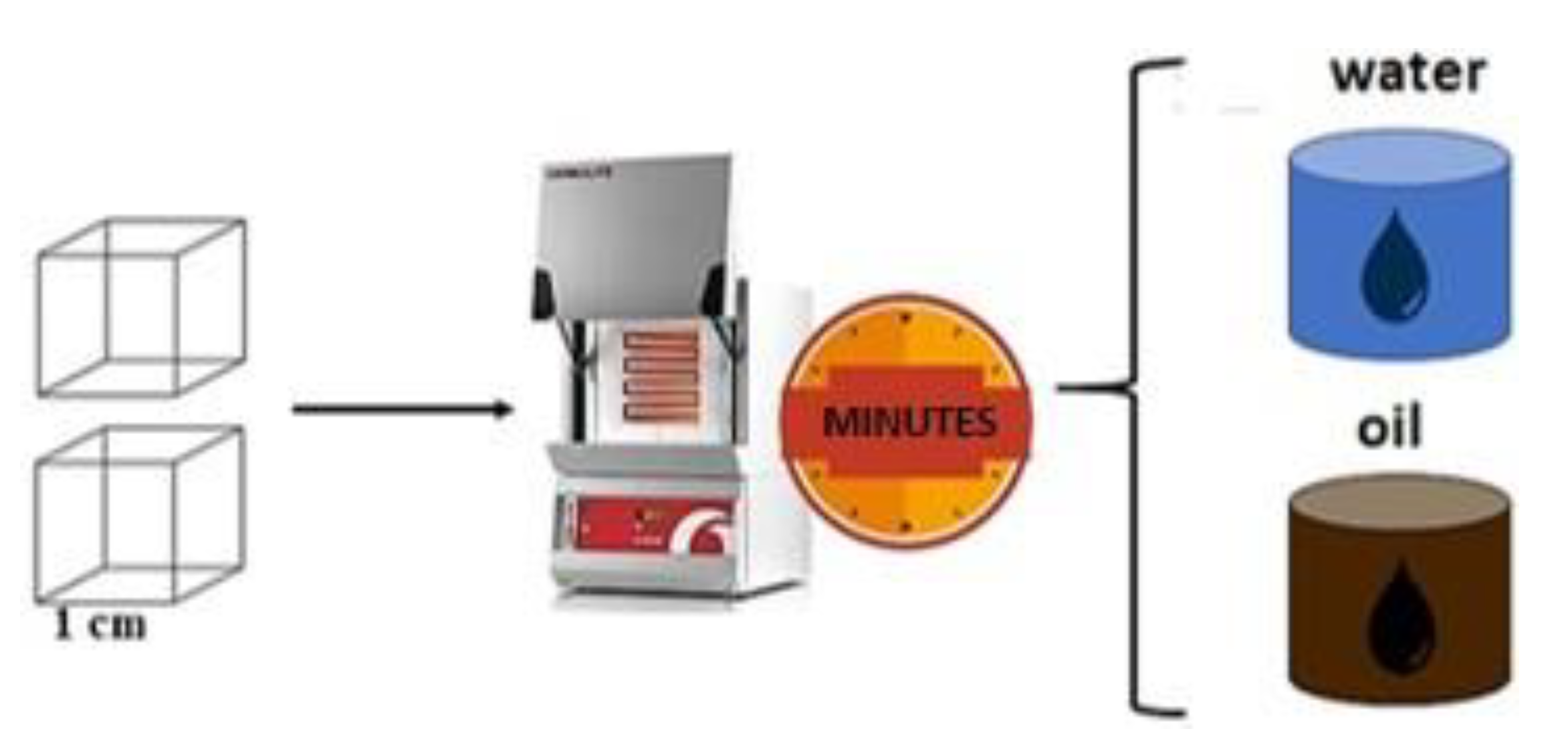
2.1. Material and Heat Treatments

A commercial high-strength, low-carbon steel, known as API 5CT, was used in this study and is referred to as AB in this paper. This API grade steel (5CT) was provided by the Mexican company Altos Hornos de México (AHMSA) (Monclova, Mexico). The nominal chemical composition of API 5CT (based in literature) is given in Table 1. The as-received material was industrially processed and provided in the hot-rolled plate condition with a hardness of 90.01 ± 5 HRB and a thickness of 1.5 cm. Subsequently, this plate was machined into samples with dimensions of 1 cm × 1 cm respectively.
To determine the effect of phase transformations on the tribological behavior of the API 5CT steel, thermal treatments were conducted in a CARBOLITE furnace model CWF 1300 (Carbolite Gero, Hope, UK) under different intercritical annealing conditions to obtain various martensite volume fractions, followed by water and oil quenching. These conditions were selected according to the best mechanical properties obtained in previous work [3,4,5] (Figure 1).
Figure 2 shows the effect of temperature on the proportion of ferrite and austenite for the API 5CT steel as a function of temperature. As can be seen, the proportion of austenite increases with the increase in temperature above A1, while that of ferrite decreases. For temperatures above the A3 temperature, the stable phase is austenite. These calculations were made using the Fe Alloys module of JMatPro software 10.2. The lower and upper critical temperatures (A1 and A3) calculated with the chemical composition of the as-received API 5CT steel were about 708.4 °C and 807.4 °C, respectively. Thermal treatments were then carried out at temperatures within the two-phase field (730, 760, and 790 °C for 2, 5, 10, and 20 min).

2.2. Microstructural Characterisation

Samples for microscopic observation were prepared using conventional metallographic techniques, which include grinding with SiC emery paper (up to 2000 grit) and polishing to obtain a mirror-like surface with diamond pastes (1 and 0.3 μm). After polishing, the samples were subjected to a five-minute high-frequency ultrasonic cleaning, using ethanol and subsequent pressure air drying. Etching was conducted by immersion in a 3% Nital solution for 7 s to reveal the microstructure, as recommended in ASTM E407 [49]. Microstructural examination was made using an OLYMPUS GX41 microscope (Tokyo, Japan) and a TSCAN MIRA3 LMU (Waltham, MA, USA) high-resolution scanning electron microscope (SEM). To determine the volume fraction of ferrite and secondary phases (pearlite, bainite, martensite) in each sample, the ImageJ software (https://imagej.net/ij/, accessed on 18 February 2025) was used. For each sample, 50 micrographs were acquired from different areas. X-ray diffraction analysis was carried out in a SIEMENS D5000 diffractometer (Munich, Germany) using Cu Kα radiation (λ = 1.5406 Å), V = 40 KeV, a current emission of 20 mA, and a 2θ range of 30–90° to confirm or discard the presence of retained austenite. Hardness tests were performed using NEWAGE INDENTRON (AMETEK, Copenhagen, Denmark) (equipment with a carbide ball indenter and a 100 kg load, with results expressed in HRB (Rockwell B Hardness). Five indentations were made on each sample to ensure reliable average results. Additionally, microhardness tests were conducted using a Vickers microhardness tester (Zwick/Roell, Ulm, Germany) on the polished specimens. At least five measurements were taken for each phase resulting from thermal treatment. A diamond indenter, which creates a pyramid-shaped indentation, was used with a 300 gf load and 15 s dwell time.

2.3. Sliding Wear Testing

After DP (ferrite and martensite) steels or steels containing ferrite and martensite (with some amounts of pearlite and bainite) were obtained, the tribological behavior was evaluated using samples of dimensions 1 × 1 cm2 in an Anton Paar pin-on-disk apparatus (Anton Paar GmbH, Graz, Austria) with a pin-on-ball coupling attachment according to the ASTM G99-95 standard [50], as shown in Figure 3. The test conditions were performed at a constant disk rotation of 0.03 m/s. Balls of α-Al2O3 of 3 mm in diameter were chosen as the pin material based on previous experience of the authors in wear studies of DP API 5CT steel [28]. The hardness of ceramic Al2O3 is 2000 HV. Wear tests were performed with loads of 5 and 10 N. The wear experiment was repeated three times at each loading condition. All the wear tests were run for 250 m under dry sliding at room temperature and a relative humidity of 45 ± 2%. The COF (friction coefficient) is directly obtained from the tribometer after the sliding test.
To evaluate the wear mechanism, samples were observed in the optical SEM and in a Nanovea PS50 optical profilometer (Irving, CA, USA). The specific wear rate was obtained by applying Archard’s equation [35].
K = V C * S
where K is the specific wear rate coefficient (mm3/N·m), V is the wear volume (mm3), C is the normal load (N), and S is the sliding distance (m). After tribological tests, a scanning electron microscope (ZEISS Sigma, Oberkochen, Germany) was used to observe and analyze the wear tracks. In addition, EDX analysis was performed for the wear debris and scars to investigate the wear mechanisms.

2.4. Corrosion Test

Prior to the corrosion test, the API 5CT steel samples were polished with emery paper, rinsed with distilled water, and degreased with acetone. The corrosion resistance behavior of steel samples with different martensite volume fractions was identified by using open-circuit potential measurement with time and potentiodynamic polarization techniques. The OCP of the samples was measured for 1800s until its stabilization. The electrochemical tests were conducted in a NaCl 3.5% electrolyte solution using a conventional three-electrode electrochemical cell that was used to conduct potentiodynamic polarization measurement using a saturated calomel electrode as a reference electrode, a graphite bar as an auxiliary electrode, and the API 5CT samples as working electrodes. The potentiodynamic polarizations were performed by using a Solartron 1255B (Sciospec GmbH, Leipzig, Germany) frequency response analyzer and consisted of the application of a cathodic overpotential at room temperature. The tests were carried out on samples with a surface of 1 cm2 on three identical samples for reproducibility validation. Potentiodynamic polarization tests were carried out at a scan rate of 1 mV/s from −250 to +250 mV versus a reference electrode with respect to the open-circuit potential (OCP). After that, the samples were observed in the optical techniques and FESEM to evaluate corrosion damage after corrosion test.

3. Results

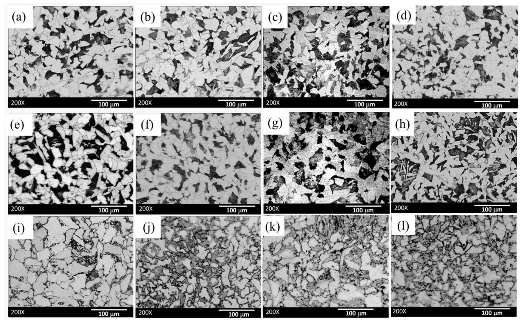
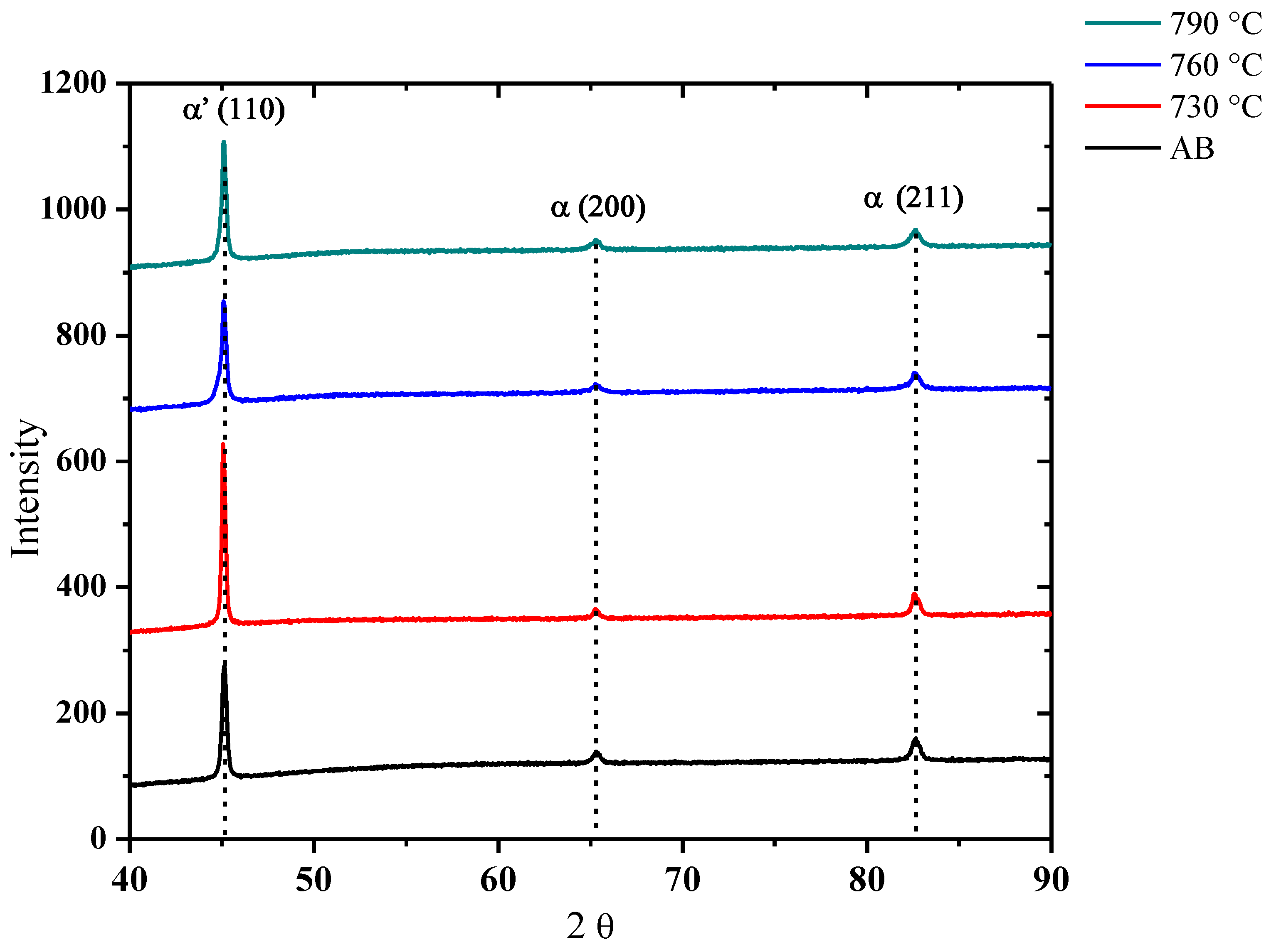
3.1. Microstructural Examination

Figure 4 shows optical microscope images of steel processed by intercritical heat treatments at 730, 760, and 790 °C for different holding times (2, 5, 10, and 20 min). The microstructure of the as-received API 5CT steel was constituted by a mixture of ferrite grains and pearlite islands, which were well distributed; however, after intercritical annealing, the microstructure consists mainly of ferrite (F, light phase) and martensite (dark phase) after water cooling or ferrite (F, light phase) plus martensite + bainite + pearlite (SP, dark phases) after oil cooling, where SP = secondary phases.
According to the literature [51] and the results in Figure 2, during intercritical annealing, ferrite and austenite coexist. On cooling, austenite can transform martensite (dark zones) with rapid cooling (i.e., for water quenching) or to a mixture of martensite, bainite, or even pearlite (dark zones) with intermediate cooling rates (i.e., for oil cooling). Pearlite, bainite, and martensite with 3% Nital etching obtain similar color contrast when observed by optical microscopy (dark contrast), making it difficult to adequately quantify them only by the difference in contrast. Therefore, these phases/microconstituents have been grouped into a value called hereinafter the secondary phase volume fraction (SPVF).
Some authors have reported that annealing of low carbon steels at temperatures between A1 and A3 followed by rapid cooling can lead to similar microstructures composed of a mixture of ferrite grains and martensite islands [52]. They used steel containing 0.035% C and obtained about 20 vol% martensite after intercritical annealing at 800 °C for 1 and 5 min. In the present work, the steel contains a higher carbon content, which makes it easier to obtain DP steels after rapid cooling as mentioned above.
The martensite amount is affected by the holding time and carbon content [41,53,54,55]. The results of the present work show that the lower the time and temperature during annealing, the greater the amount of pearlite and bainite and the lower the amount of martensite. Higher temperature within the two-phase (ferrite + austenite) field leads to a higher amount of austenite (Figure 2) and thus a higher amount of martensite. This behavior is consistent with the results of other authors [56], who obtained DP steels after water quenching of a low-carbon steel [29,57]. Therefore, it is expected that in this case, with higher temperature and annealing times (and water quenching), SPVF is more affected by the presence of martensite. For lower temperatures and annealing times (oil cooling), SPFV can be more affected by the lower amount of martensite and a higher amount of bainite and pearlite. For rapid cooling rates, the iron and carbon atoms in Austenite do not have time to form bainite or pearlite, and instead the material undergoes a diffusionless transformation to martensite.
A comparison between the morphological characteristics of the as-received API 5CT steel and those of samples annealed at 790 °C for 20 min is shown in Figure 5. The former mainly exhibits a mixture of ferrite (F, equiaxed grains) with pearlite (P) islands of lamellar structure (Figure 5a,b), while the second shows a microstructure constituted mainly of ferrite (F) and blocky martensite (M) (Figure 5c,d). These results confirm that samples subjected to water quenching are mainly constituted by a mixture of ferrite and martensite such as that required in DP steels.
Results of XRD measurements conducted in samples with the lowest and highest martensite volume fractions at 730 °C, 760 °C, and 790 °C are presented in Figure 6. These results show that the austenite formed during intercritical annealing transforms to martensite or even to a mixture of martensite, bainite, and pearlite upon cooling, and thus it cannot be detected at room temperature as a result; this is in accordance with the findings of other authors [23,41]. In addition, since the main diffraction peaks of ferrite, bainite, and martensite are very similar to each other, there are no apparent changes in the main diffraction peaks independently of thermal treatment conditions. Ferrite has a BCC crystalline structure, and martensite has a BCT structure, and both diffract at 2θ angles of about 45, 65, and 82°. This can explain the marginal change in the XRD peaks position in DP. The absence of diffraction peaks corresponding to the FCC structure (43, 50, 74, and 90°) confirms that retained austenite is not present [58].
Grain size significantly impacts the mechanical properties and wear resistance of metallic materials [59]. Therefore, grain size was verified according to ASTM E112-13 [59] using quenched samples. The average grain size of untreated samples is 6, while for heat-treated specimens at 730 °C, 760 °C, and 790 °C, it remains similar, reaching a size of up to 9. As shown in Table 2, untreated API 5CT steel has a ferrite grain size of around No. 6 ASTM E112, while heat-treated samples show a mix of large and small grains with an average size of 8–9 ASTM E112.
Table 2 also shows that the grain size of heat-treated steel at 730 °C, 760 °C, and 790 °C is about 25% smaller than untreated API 5CT. This effect is related to the nucleation and growth of austenite during intercritical annealing. As the holding time or heating temperature in the intercritical range is increased, the effective ferrite grain size seems to shrink as a result of ferrite “consumption” by the growing γ-phase. This behavior has been studied in detail by N. Fostein [60].
Table 3 shows the volume fraction of ferrite (F) and the volume fraction of secondary phases (VFSP = martensite, bainite, pearlite) as a function of the intercritical temperatures (730, 760, and 790 °C). Worthy of mention is that higher VFSP is related to a higher volume fraction of martensite, especially when using water as cooling media; however, considering that martensite, bainite, or pearlite acquire a similar contrast with Nital etching reactant (dark contrast by optical microscopy), they are considered together in the term VFSP. It is clearly observed that the VFSP increases for a larger holding time and higher temperature, which can be associated with the increase in the amount of austenite during annealing [61]. The specimen annealed at 790 °C for 20 min showed the highest VFSP (50%) after water cooling, which is expected due to the combination of a higher temperature and annealing time and faster cooling rate. For the same temperature, but for a holding time of 2 min and oil cooling, the VFSP was only 25.14%, which relates to the lower amount of austenite formed during annealing treatment.
The viscosity of the oil generates different heat dissipation with respect to that achieved with water, so it is expected that a lower martensitic phase transformation is achieved with oil cooling. The results obtained for the case of oil-cooled specimens show VFSP percentages of 27.48% (730 °C, 20 min), 28.56% (760 °C, 20 min), and 38.52% (790 °C, 20 min). For the lowest temperature and smallest holding time, the VFSP was 13.25% (730 °C, 2 min). Some authors [62,63] have reported values of martensite fractions around 20–25% for low-carbon steels after quenching; the variation of the results of the president work depends on the annealing conditions.
Table 4 shows the variation of hardness as a function of holding time at 730, 760, and 790 °C for each quenched media. In general, the specimen hardness is proportional to the VFSP. As can be seen, the highest hardness (113 HRB) is obtained for the highest VFSP in samples with the largest intercritical holding time (20 min) and the highest temperature (790 °C). The lowest hardness (~92 HRB) was obtained in samples with the smallest holding time and lowest temperature. The increase in hardness with the increase in the intercritical temperature and annealing time can be attributed to the higher amount of martensite or martensite + bainite, and vice versa, the reduction of this property for the smallest time and annealing temperature can be related with the decrease in the amount of these phases (and even with the presence of pearlite). It is noticed that oil cooling produces lower hardness values than water cooling; this is related to the differences between the heat capacity rates of both media. The higher the cooling rate is, the greater the possibility to form martensite or martensite + bainite (i.e., for water cooling), and thus the higher the hardness.
It is well known that mechanical properties are controlled by martensite-ferrite fractions, martensite carbon content, etc. However, the carbon content affects the martensite hardness and the hardenability [30]. Martensite is a metastable iron phase supersaturated in carbon that is the product of a transformation of austenite. Due to the absence of diffusion processes during the phase transformation, the chemical composition of the martensite is identical to that of the austenite from which it is formed. Instead, the carbon content of the martensite, which determines its hardness and shape, depends on the nominal content of the base steel and the intercritical quenching temperature [47,63]. Previous studies [18,30,47,63] have mentioned that the increase in the hard martensite volume fraction and the decrease in the soft ferrite volume fraction result in increasing the bulk hardness.

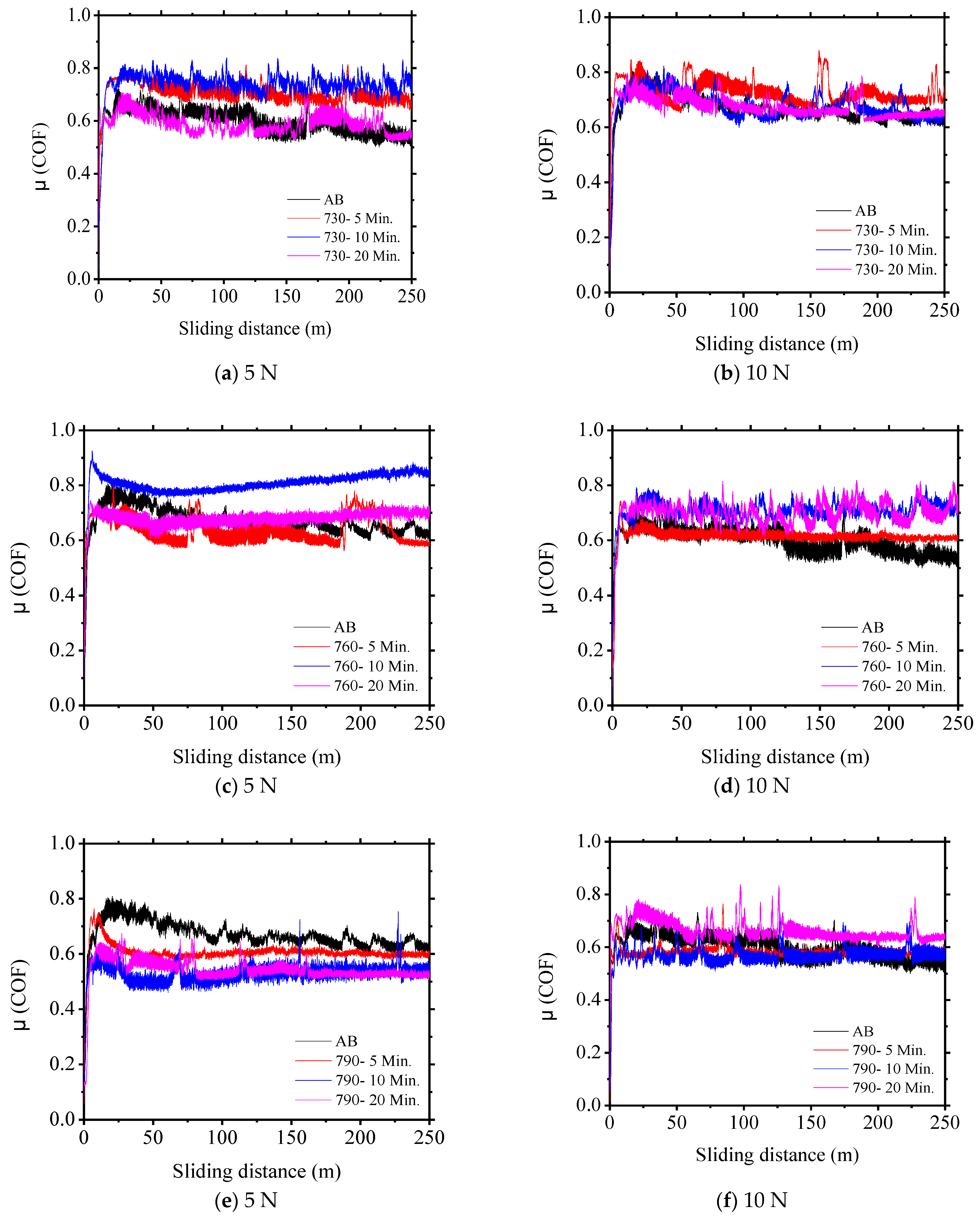
3.2. Coefficient of Friction (CO)

The influence of the microstructure on the wear behavior of the API 5CT specimens was studied by performing wear tests at 5 and 10 N. The influence was determined by calculating the wear rate of the dual-phase steel samples and the dynamic COF. A similar tendency was observed on tribological tests as the representative behaviour during sliding; the plot in Figure 7 shows the evolution of the µ in the tribological pairs with loads of 5 and 10 N. The friction forces behaviours involved between the tribological pairs are shown in Figure 7. The friction coefficient varies greatly with time, but overall, it shows a regular pattern. According to the results of dynamic friction coefficients of the specimens of API 5CT, two stages can be clearly distinguished in all the COF curves examined. The first stage is relatively very short (less than 5% of the total sliding time), and the friction coefficients of all materials reach a steady-state value within 25 m. In this stage of friction, the contact area between the rubbing materials is small, and the materials are not fully in contact, resulting in a lower friction coefficient [64,65]. The second stage is observed, where the COF rapidly increases up to reach a constant level. This second stage where the COF hardly varies corresponds to the steady state stage [66]. This variation of the coefficient of friction at the beginning of a wear process is usually called “running-in” or “break-in” and can be attributed to the following: (a) changes in the chemical composition of the surface (mostly formation of oxides) due to friction processes; (b) effects due to the increase in the local temperature in the contact zone; and/or (c) mechanical breakage of a surface oxide film or changes in the geometry of the contact surface. It is observed that the friction coefficient (µ) decreases linearly as holding time increases in all samples. The mean friction coefficients for all materials are based on the calculation of the steady-state friction coefficient during the sliding time. The average values of the COF in both quenching media were 0.62–0.80 as a function of sliding time. These results are in accordance with the findings of other authors [23,29,67,68], which show that the COF increases when decreasing the martensite volume fraction. The decrease in wear coefficient may be attributed to the decreasing wear rate dominating over the decrease in the real area of contact due to increasing hardness [68].
Table 5 shows the values of COF for all specimens. A clear correlation of the COF with the VFSP can be observed. Initially, comparing the data sets for specimens with VFSP values from 25.8 to 50%vol, it is seen that a steep increase in the COF takes place concurrently with the sliding time. The COF values vary significantly between 0.62 and 0.80, while from the fixed contact between the counterpart and specimens with smaller VFSP values, a distinct dependence emerges. In this case, the COF slightly decreases with time. Moreover, even for data obtained at each given sliding time, a strong dependence on the COF with the VFSP is observed. It is noticed that the minimum COF values correspond to specimens with the lowest VFSP, and the maximum COF values correspond to the specimens with the highest VFSP.
On the other hand, regardless of the hardness of steel samples, the COF is consistently higher for the samples where the minimum load of 5 N was applied, while at the load of 10 N, an intermediate COF value was obtained, with the lowest COF observed for the samples under the action of the 10 N load. The application of higher load can decrease the roughness of the samples, increasing the local temperature by the friction force, which encourages the formation of lubricating oxide films at the contact interface. At the lower load of 5 N, the COF profiles initially develop a marked curvature until reaching the stability margin in the development of abrasive-adhesive wear. The thermal effect of contact friction at the lower load promotes a less stable oxide film that makes the COF signal slightly noisier throughout the wear test [65,69].

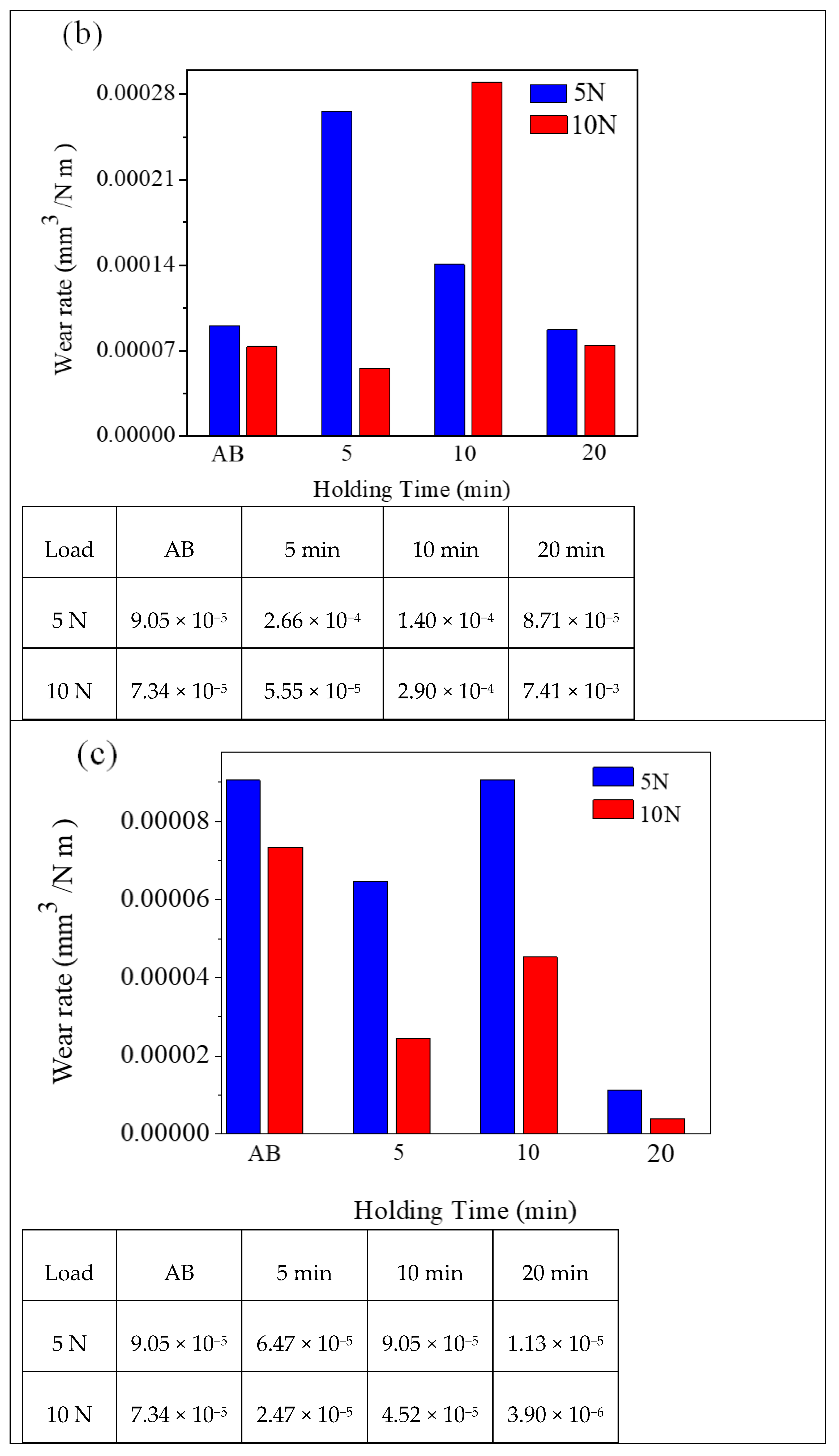
3.3. Wear Rate and Wear Coefficient K

Figure 8 shows the wear coefficient (K) behavior of the API 5CT specimens depending on the sliding distance rotating against an Al2O3 pin with loads of 5 and 10 N. It is evidenced that the rate of wear from API5 CT heat treatment at a higher temperature (790 °C) is lower than for the base material analyzed (AB), achieving a decrease in the rate of 50%, which depends on the VFSP, and the load applied, as seen in Figure 8. Likewise, the higher wear resistance of the specimens after heat treatment time (20 min) increased due to the increase in the presence of hard phases (i.e., martensite and/or bainite), which increase the resistance to wear. With this condition, samples with lower VFSP exhibit lower wear resistance than those with higher VFSP. In addition, the minimum wear occurs on the sample with the higher VFSP.
As can be seen from Figure 8a–c, with an increasing load, the wear rate decreases in all intercritically annealed (IA) samples in comparison with the as-received API 5CT steel. The wear rate of API 5CT is lower. This indicates that this type of steel exhibits good wear resistance in both conditions. However, the sudden increase in the Archard coefficient observed at all temperatures evaluated after 5 and 10 min of holding time is exclusively associated with the changes in the mechanical properties and microstructural features of the steel due to formation processes, phase transformations at the evaluated temperature, and the coefficient of friction. The results indicate that there is no significant effect between wear coefficient rates and load applied; however, increasing the martensite content (or the VFSP value) in steel tends to decrease the wear coefficient values, that is, it decreases the wear rate of the dual phase steel, an effect that is observed with greater intensity at a temperature of 790 °C, a temperature (20 min) at which the steel test pieces obtain the highest hardness (113 HRB), which is consistent with the greatest amount of martensite and the highest hardness values observed for these conditions.
A high wear rate is observed in samples annealed for 10 min at 730 and 760 °C, but it then decreases when the temperature is increased to 790 °C, and the effect is more significant for a longer annealing time. The wear resistance increases with the increase in the amount of martensite (or the VFSP value) and the decrease in the amount of ferrite. Bahrami et al. [70] reported that high-performance steels can have the formation of a homogeneous protective oxide film on harder surfaces, which can protect the steel from metal-metal contact against wear. So et al. [71] reported that there is no evidence that wear rate is directly proportional to the load applied during oxidative wear, due to the formation of a solid lubricant. As shown in the present work, the highest wear rate occurs in the steel thermally treated at 730 °C, i.e., in the steel with lower martensite content (or VFSP value) and a higher ferrite (soft phase) amount. The presence of a higher amount of ferrite favors the material removal, which, when released, can weaken the oxide layer formed, thus decreasing wear resistance [71]. However, the critical thickness of an oxide depends on various factors such as the nature of the oxides and the different sliding parameters (speed, temperature, environment, and load), so if a critical thickness is not reached, wear increases [72]. Another important factor that determines the intensity of wear is the surface roughness and hardness of the material, due to the transition in the wear mechanism from a predominantly microcutting one to a predominantly microgrooving one [73]. Similar results were obtained by Tang et al. [74], who studied the wear behavior of dual-phase steels; ferrite facilitates the formation of cracks during tribological testing, which increases the COF and the wear rate, as observed in the present work.

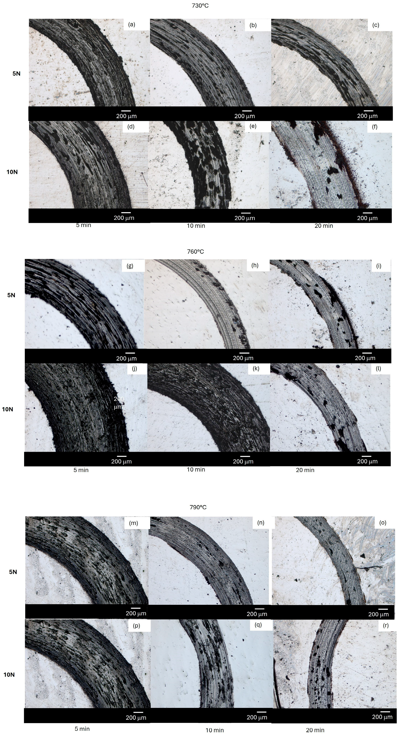
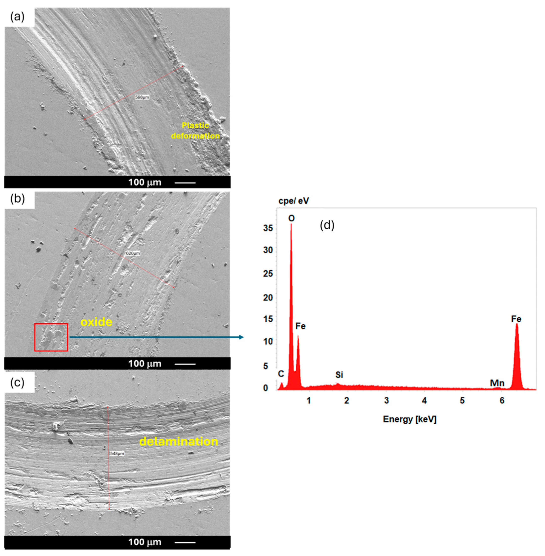
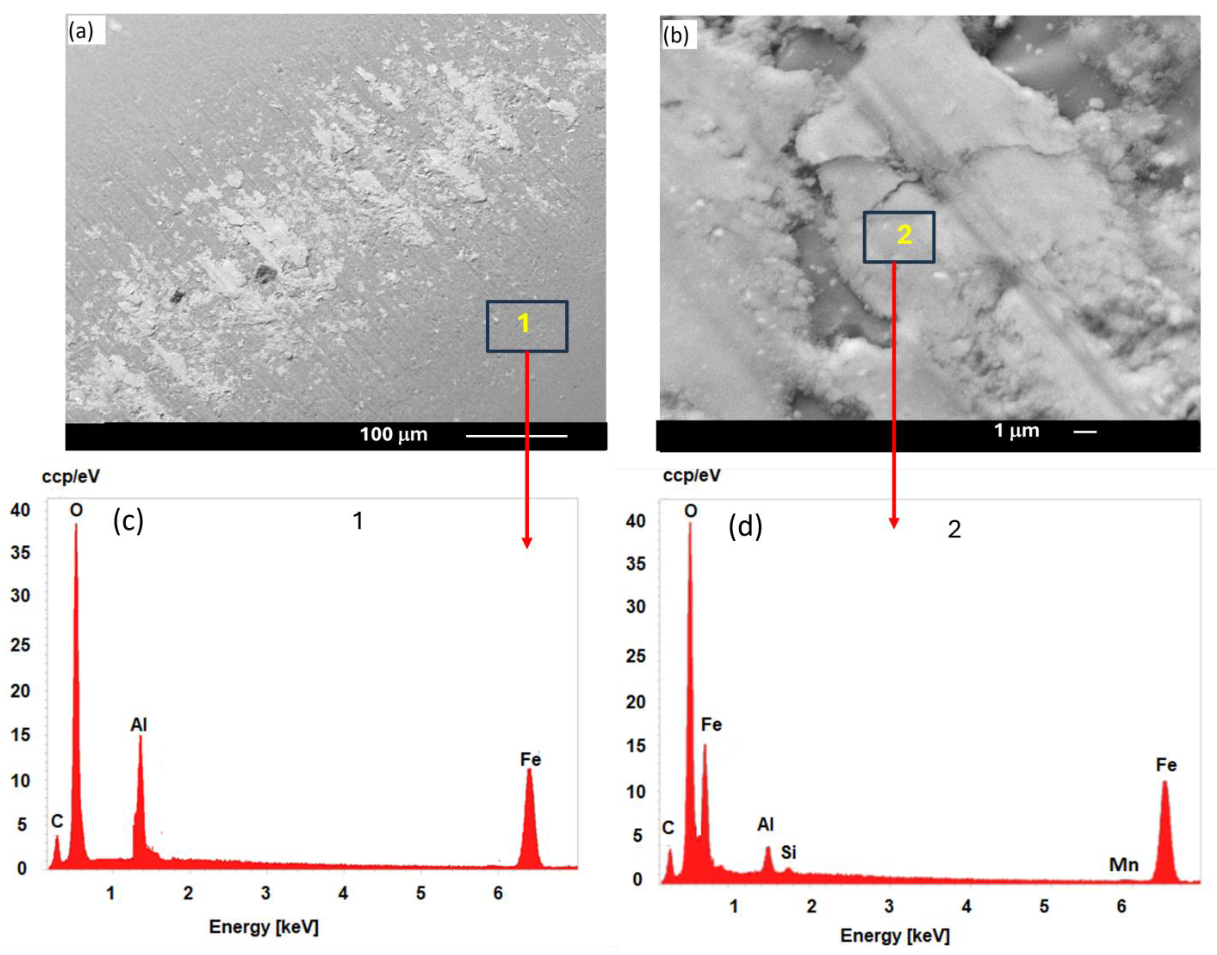
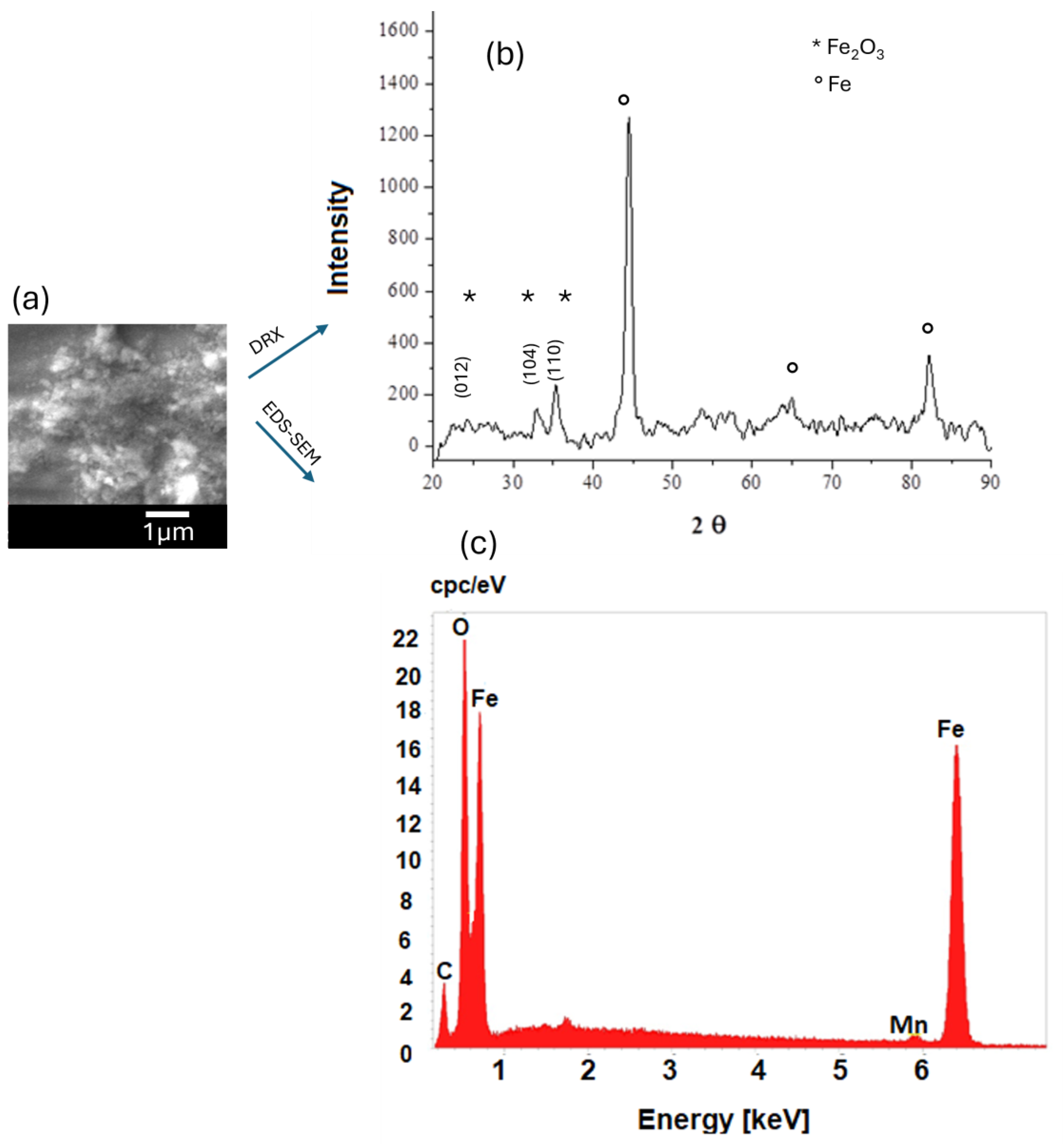
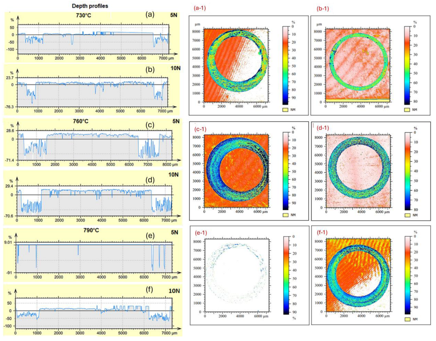
3.4. Optical and SEM Micrograph of Contact Surface

To further analyze the wear mechanism, a comparison of the worn track surfaces of the API 5CT samples under a constant sliding distance of 250 m and loads of 5 and 10 N of the specimens heat treated at 730, 760, and 790 °C with different holding times of 5, 10, and 20 min and a speed of 1 cm/s was conducted to observe their morphologies, as depicted in Figure 9. In general, wear tracks are characterized by surface deformation in the form of smooth surfaces. Longitudinal grooves are parallel to the sliding direction. It is evident that during the wear tests, surface damage occurred due to the constant, cyclical, mechanical contact of the API 5CT grade steel surface with the alumina sphere. In addition, it is evident that all worn surfaces are covered with oxides, which are distributed over the surface. Moreover, there are noticeable fragments of wear debris (debris) covering the worn surfaces and on the periphery of the wear tracks, which are the product of the defragmentation of the oxide layers, which tend to compact and sinter as the load increases from 5 to 10 N. Commonly, the wear debris generated during the wear process is oxidized and hardened into high-hardness particles, which are mixed in the contact area, resulting in small fluctuations in the friction coefficient, and tend to generate deeper grooves or scratches in the material, that is, it acts as a third abrasive body on the surface. In this regard, Inman et al. [75] mentioned that the compaction of oxides is a product of high temperatures and loads applied during a tribological contact; the greater the compaction, the better the wear resistance of metallic alloys. Additionally, the worn surface width obeys a directly proportional relationship between the substrate and the hardness of the counterpart.
Selected SEM images of the wear track morphologies are shown in Figure 10. Figure 10a corresponds to steel samples thermally treated at 730 °C for 20 min, while Figure 10b,c correspond to the steel samples IA at 760 and 790 °C at 20 min. At these conditions, the microstructure of the API 5CT steel has reached its maximum hardness. Thus, the surface is not excessively scratched, particularly at the load of 5 N (Figure 10a), which indicates a moderate abrasive wear mechanism derived from the plastic flow of the softer surface. At a higher load, the formation of wear particles during the test could produce three-body abrasive wear generated by a scraping mechanism, as evidenced by the wear trace at 10 N in the micrograph of Figure 10b. The lighter regions correspond to abrasion strips due to abrasion or plowing of the particles, which causes plastic deformation and material removal, producing grooves on the surface. The scraping along the path of wear is characteristic of the generation of debris that causes a more severe contact for a metallic surface [15,46]. It is observed that during the sliding wear test, the friction energy is dissipated in the form of heat, and this heating produces surface oxidation in patches, which can be observed in the SEM micrograph in Figure 10. Figure 10b shows the presence of darker parts, which refers to the oxidation of the worn surface, which is confirmed by the EDS analysis of the region marked in a red box in Figure 10b. Therefore, the oxidation process can be referred to as a wear mechanism for this type of steel, which implies that in addition to the microstructure, surface oxidation also exerts an influence on the tribological performance, since during sliding, they fracture, as they are hard and brittle, and therefore cracks can initiate and propagate into small oxidized fragments under the cyclic influence of stresses, which will become micrometric scale particles that will be trapped in cracks and that could increase their propagation or cause damage by three-body abrasion. The predominant wear mechanisms are abrasion, oxidation, and delamination.
The combination of two mechanisms is noted during the wear processes: abrasion and some microcuts are seen in the white lines. Additionally, the presence of dark zones is related to the ferrous oxide as a product of tribochemical reactions that act as lubricants in the tribological system. Nonetheless, plastic deformation and detachment of the material are observed, which can increase the abrasive contact in the tribological system at the end of the test [65,76]. In general, wear tracks are characterized by surface deformation in the form of smooth surfaces. Longitudinal grooves are parallel to the sliding direction. SEM images also reveal that the wear mechanism is not only abrasive but mainly oxidative. Especially at the periphery of the track, larger oxidized areas are observed along the wear track. These marks such as scratches, cracks, or extrusions can be used to classify the different types of wear mechanisms that occurred in the specimens during the test.
Although three mechanical and chemical surface degradation mechanisms (abrasion, delamination, and tribological reaction) were found during the sliding test of the API 5 CT with and without IA samples, the predominant mechanism was adhesion, which gives rise to the abrasion of transfer layers. Figure 11a–c shows the API 5CT surfaces both sliding against the alumina counterface at a sliding distance of 250 m, a speed rate of 1 cm/s, and a normal load of 5 N and Figure 11d,e. The morphology of the wear tracks shows the presence of compact waste material in the wear tracks, eventually forming a transfer layer that is formed because of the agglomeration and compaction of waste material (debris), Figure 11c. However, the adhesion of these layers subsequently generates the release of both materials by the abrasive action of the hardened transfer particles and gives rise to the shear, fracture, and delamination of the compacted layer, which creates surface abrasion grooves (Figure 11d–f). According to the images, the manner of detachment of the debris confirms the plastic contact experienced by the tribological pair, so different grooves and flanges running parallel to each other in the direction of sliding are visible. This is in accordance with the first stage of the curves of the friction coefficient, which were caused by lapping the friction couple, and thus the sudden changes in the wear mechanism.
The SEM images shown in Figure 12 exhibit the morphology of the testing surface of the counterpart (alumina balls) against API 5CTsteel surfaces at 10 N. The size of the contact area is proportional to the width of the wear track and hence to the wear rate of the material. The largest diameter is presented by the wear track of API 5CT with a lower amount of martensite and lower hardness (92HRB) in conditions of higher load (10 N). The surface and loss of material in the counterpart sliding with API 5CT steel was generated by the presence of abrasive particles, leaving a rough and scratched surface with a large amount of wear residue adhered along the entire footprint. According to elemental EDS analysis (Figure 12), Fe and O are present on the abraded surface. Quantitative EDS results revealed that the presence of Fe ranges in the range of 9.35% on the back side of the abraded surface. The front side of the abraded surface of the counterpart consists mainly of Al and O. The presence of Fe and O is effectively indicative of the presence of a triboclay on the abraded surface of the metal substrate, which may act as a lubricant [33]. When the normal load is increased to 10 N, the oxide layer breaks downward due to the high forces and is partially removed from the contact. At such a load, the tribochemical film coverage in the wear track is reduced, generating more severe adhesive wear.
The EDS results indicate that the base steel samples are more likely to form layers of iron oxide that temporarily reduce the actual contact between the two surfaces; however, they quickly fail and act as abrasive particles as well. This situation is corroborated by the evaluation of the worn surface of the counterpart where the adhesion of material from the steel surface is observed (Figure 12).
The oxidative wear mechanism involved in these dry sliding wear tests is further explained, confirmed by the XRD diffractogram of particles collected from debris, shown in Figure 13a–c, and it is evident that both the XRD diffractogram (Figure 13b) and the EDS elemental analysis (Figure 13c) reveal two phases, hematite (Fe2O3) (ICSD-201096) and alpha iron (α-Fe). The possibility of oxide formation is feasible under the process conditions, as shown by the calculations of the free energy of formation for the oxidation reaction of Fe in its most stable forms, which are ΔGFe3O4 = −1102.8 KJ/g mol and ΔGFe2O3 = −814.71 KJ/g mol, thus confirming that the formation of a denser film of iron oxides is favored since, as reported by Sue et al. [77], the formation of films as a result of tribocorrosion reactions is favored because instantaneous temperatures of 200 to 400 °C can be reached [77].
Finally, the damage on the surface of the steel substrates with and without IA was characterized by the depth of the wear marks generated on the surface of the substrates. Figure 14 shows the comparison of the depths of the wear marks obtained at different heat treatment temperatures of 730, 760, and 790 °C at a time of 20 min, at a constant sliding distance of 250 m and applying a load of 10 N on API 5CT steel substrates. It is observed that there are protrusions along the edges of the wear tracks, which can attributed to the pronounced accumulation caused by the plastic deformation during the rotation of the abrasive alumina ball [77]. The width of the grooves generated by abrasion is approximately 500 μm. Deterioration is evident on the surface, showing grooves up to 100 μm deep at a shorter heat treatment time and up to 40 μm when the heat treatment time increases to 20 min, due to the increase in martensite present as the holding time of the thermal treatment increases, a situation that is repeated at both temperatures evaluated in this project. The profiles obtained in all conditions show a heterogeneous line at the periphery due to the surface roughness. In general, it is observed that the wear track profiles are similar, which show that during the sliding of the surface and the alumina counterpart, there is detachment and fragmentation of the oxide tribo-film formed during sliding, generating abrasive wear on the surface as observed in the analysis of the substrates by scanning electron microscopy. Likewise, the irregularity of the surface of the grooves indicates that adhesion occurred between the pin and the surface of the substrates, forming a layer that modifies the wear behavior, as mentioned previously. In this regard, various authors mention that the formation of a tribo-film of oxides together with the wear residues acts as a third body in the system, so greater material detachment is to be expected during sliding. It is evident that the wear depth increases in samples with lower martensite amount, but the degree of wear growth decreases with increasing martensite amount and load, suggesting that the impact of the material wear surface under high loads applied gradually diminishes, providing evidence of good wear resistance.
Finally, the above results suggest that the hardness of the substrates and the VFSP appears to indeed be a key parameter affecting the COF and the wear rate. In the present work, under sliding wear conditions, the alumina counterpart exhibits mild abrasive wear and oxide adhesion from the API 5CT steel substrate, which shows a change in the nature of the oxide generated during sliding as a function of sliding velocity. The two main types of oxidized debris collected are Fe2O3 and Fe-α. The Fe2O3 oxide recovered is the expected one. This oxide is found with a low temperature below 450 °C [78], associating a reduction in COF and wear rate with increasing temperature with the variation in Fe2O3 iron oxide present on the surface.

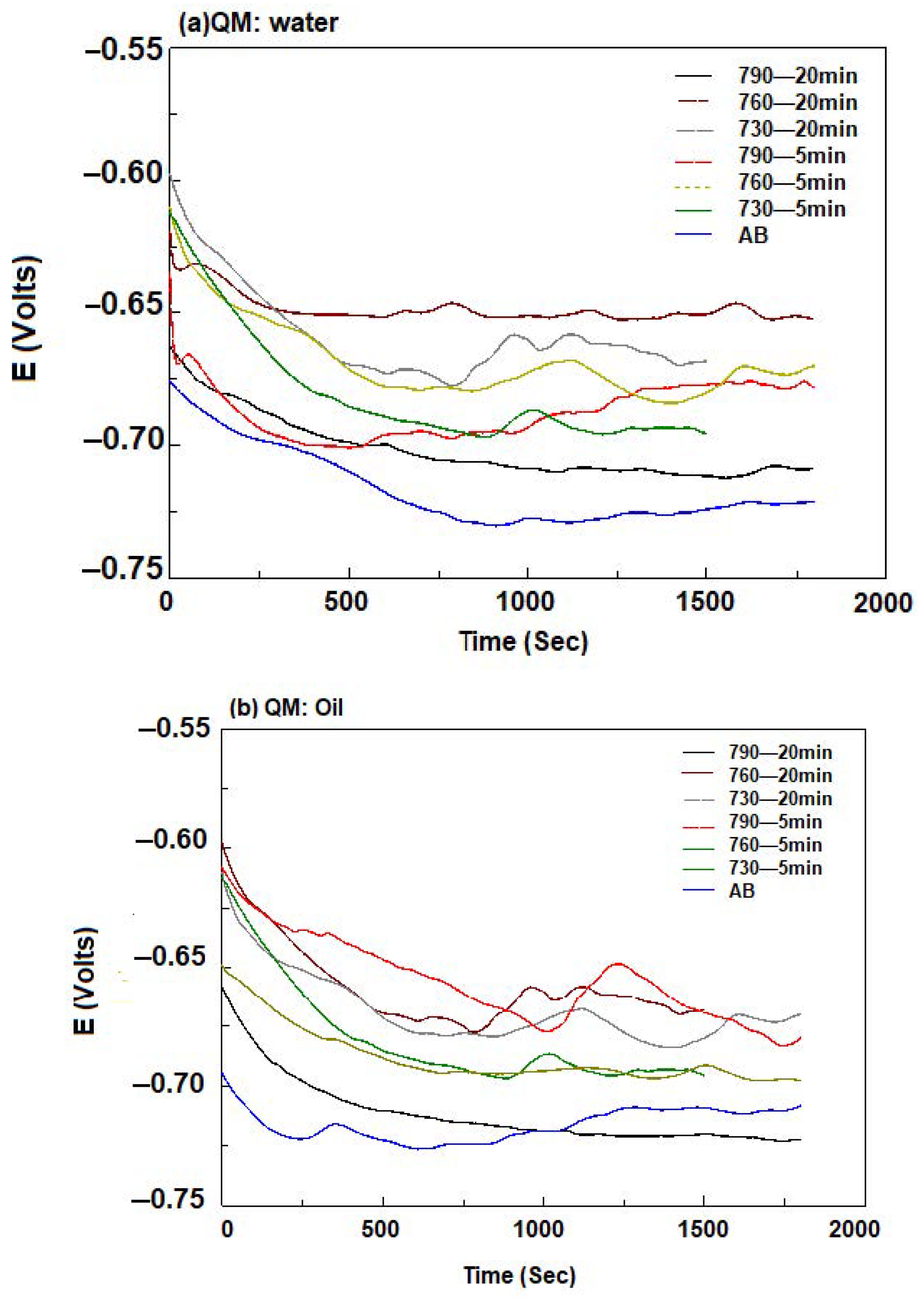
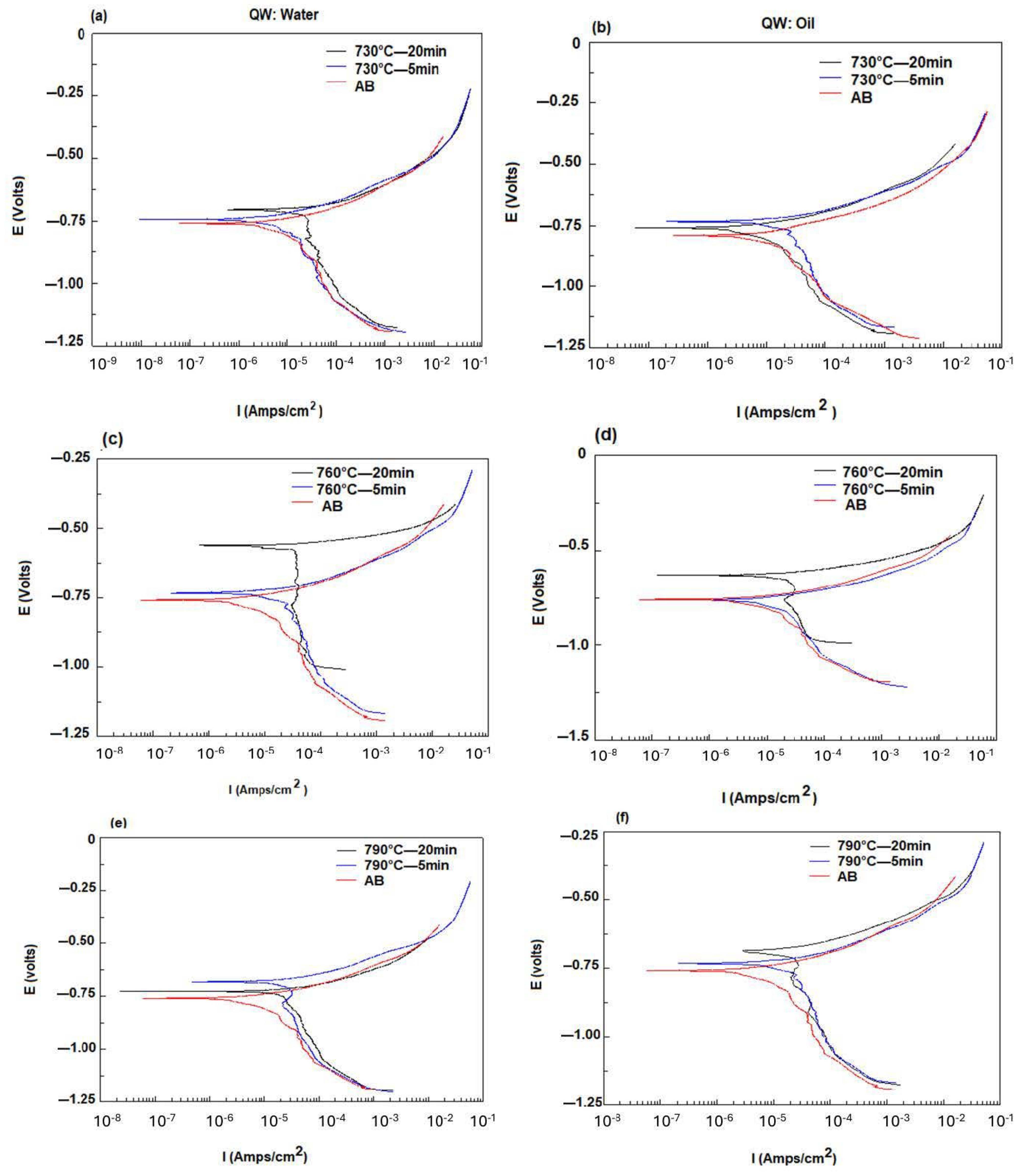
3.5. Electrochemical Behavior of API5CT

The rates of change of the OCP and the potentiodynamic polarization curves of API 5CT steel samples are shown in Figure 15a,b and Figure 16, respectively. The corrosion parameters using the Tafel equation are measured and are given in Table 6. Figure 15 shows the results obtained from the application of electrochemical techniques on API 5CT steels with and without IA at 730, 760, and 790 °C, immersed in a 3.5% NaCl saline medium. Compared to as-received steel samples, the treated samples exhibited a cathodic shift in OCP and corrosion potential (Ecorr) in both quenching media.
The evolution of the OCP with respect to time presents typical curves that show a fall in the initial period that decreases its slope until it stabilizes. That is, it is observed in all cases where at the beginning of the curves a more positive potential is presented; however, as time passes, it decays, indicating a cathodic behavior where the surface of the test piece that acts as a working electrode begins to degrade. However, after a certain time (500 s), this potential tends to stabilize and increase the potential value (Ecorr). This increase is usually due to the formation of a passivation layer on the surface of the metal when in contact with the electrolyte. This behavior indicates greater electrochemical stability. It is worth mentioning that the variation in potential under OCP conditions is specifically due to processes occurring around the electrolyte–metal interface. Furthermore, the stability of the open circuit potential (OCP) is achieved once the chemical species formed during the process reach a degree of uniformity on the surface [79]. At this point, it can be observed that the present microstructure and the properties of the steels have a close relationship since the changes in volume percentages of the martensite and ferrite phases that take place during heat treatments significantly influence corrosion resistance. The difference between corrosion potential values under open circuit conditions (Ecorr) corroborates that the microstructural changes that occur during heat treatment modify the electrochemical activity of API 5CT steels. According to the results obtained, it is observed that a uniform microstructure promotes the corrosion resistance of steel. In this context, Zadeh et al. [80] have reported beneficial effects on galvanic corrosion due to the presence of acicular martensite in laser-treated steels (LPBF). Similarly, Ochoa et al. [81] have reported that martensite tends to corrode due to the high activation energy. In this regard, Chen et al., 2002, evaluated the corrosion processes of a dual-phase steel, where it is mentioned that the corrosive process consists of two stages, the cathodic relationship between martensite/ferrite and the dissolution-separation of the phases [82].
After the microstructural analysis, the corrosion resistance study was carried out using the linear polarization technique. The results of the electrochemical tests are shown in Figure 16 for both cooling media (water and oil). On the Tafel plot, the overall current density results of oxidation and reduction reached equilibrium at a cross point on an anodic slope for a steel dissolution chemical reaction and a cathodic slope for an oxygen transformation reaction. It should be noted that when the steel specimen with the ferrite– martensite structure corrodes in 3.5%wt NaCl solution, the following reactions occur on the steel surface, with ferrite acting as an anode: [83]
Fe → Fe2+ + 2e (anodic)
O2 + 4 H2O + 4e → 4 OH (cathodic)
In general, a similar polarization mechanism is observed in both water and oil cooling media conditions. The curves show that the corrosion process basically consists of superficial anodic dissolution. In addition, the curves are characteristic of a process controlled by activation and mass transport through the electrolyte, with the reduction reaction predominating and controlling the corrosion rate. It is observed that the anodic region does not present passivation; however, it is observed that for the case of the test pieces treated at temperatures of 760 °C in both cooling media, the corrosion potential (Ecorr) was more positive and the current density lower with respect to the API 5CT steel test pieces. This effect is observed more clearly in the curves obtained in the test pieces where oil was used as the cooling medium. The base steel shows the most active corrosion potential (Ecorr) of −750 mV), while the Ecorr for the steel treated at 760 °C cooled in both water and oil show more positive tendencies of −530 mV and −630 mV, respectively. The results show a decrease of 200 to 100 mV depending on the cooling medium used, which confirms greater resistance to corrosion after applying intercritical heat treatment at 730, 760, and 790 °C.
Results of corrosion polarization studies of the API 5CT samples with respect to a standard calomel electrode are shown in Table 6. The data for the corrosion potential (Ecorr) and corrosion current (Icorr) shown in Table 6 have been derived from the experimentally obtained cathodic and anodic polarization curves using Tafel’s linear extrapolation method and are presented in various corrosion current density icorr values, where the lower value has better corrosion resistance properties. The Ecorr of the steel samples becomes noble with the increase in the martensite volume fraction. The corrosion current (Icorr) decreased, while the martensite fraction volume increased.
In conclusion, it is observed that the heat treatment temperature is important since the fraction of martensite and ferrite present in the microstructure depends on it. At the different temperatures evaluated, it is shown that the heat treatment temperature of 760 °C achieves the highest corrosion resistance because the smallest value of current density (icorr) is achieved, with respect to those achieved at 730 and 790 °C, and although the current corrosion density and the amount of martensite/ferrite in the API 5CT steel matrix do not follow a specific trend, the corrosion rate increases inversely with the volumetric fractions of martensite. Int this context Kumar et al. [43], report contradictory corrosion resistance behavior in a percentage of martensite present in a range of 30–50%, since the possibility of formation of galvanic pairs between the two phases present increases. The corrosion behavior of API 5CT steel depends mainly on two factors: the fraction of ferrite-martensite phases and the existence of microcells that induce galvanic corrosion between them, where the ferrite phase acts as a micro anode and the martensite acts as a micro cathode. In the reactions involved in the corrosion processes, there is an exchange of electrons, and the speed at which this exchange takes place determines the degree of degradation of the material in such a way that the time constant is an important factor that determines how quickly the corrosion process takes place. In this regard, ref. [84] reports a higher corrosion rate in steels with 50% martensite compared to 25 and 75% due to carbon content, martensite content in the microstructure, microdeformation, etc. The residual stress of the martensite transition changes the electronic properties of the steel matrix and decreases the hydrogen overpotential in the evolution reaction at the cathode. The study also mentions that martensite increases the hardness of the steel and likewise the corrosion resistance properties. This reported behavior is like that presented by the curves achieved, since at the temperature of 790 °C, there is a greater fraction of martensite with respect to the temperature of 760 °C, which are the temperatures that present the lowest current density values. This indicates that intercritical annealing could induce structural changes in the surfaces of steel API 5CT, which modified their corrosion parameters.
Figure 17a shows the corrosion morphologies of the API 5CT base steel, and Figure 17b corresponds to API 5CT-IA at 790 °C for 20 min, after corrosion tests in a 3.5% NaCl. Severely damaged surfaces are observed with the presence of pits with a semi-spherical geometry, as well as the presence of grain boundaries revealed by a chemical attack, which shows the damage suffered by the metallic material due to pitting corrosion. Additionally, the base steel is observed to have had a localized loss of material, which appears as a pit having an approximate size of 25 µm, although certain reliefs are clearly visible, directly related to martensite, since in previous analyses, it had been stated that this type of microstructure is more resistant to corrosion than ferrite. In addition, these irregular pits or voids (1 μm) are present in the chain-like network of martensite after the dissolution of adjacent ferrite [85]. Therefore, it can be determined that the dual-phase steel is susceptible to micro-galvanic corrosion when exposed to an NaCl solution [82]. Since martensite is much more active than ferrite, it is common for the most predominant damage to occur in areas with a greater presence of martensite, that is, the entire surface of the steel is not damaged, as this type of corrosion is preferential. This indicates that the nearby ferrite matrix suffers from a preferential anodic dissolution. A lower degree of corrosion and pitting size are observed on the heat-treated samples with respect to the base steel. This confirms their lower degree of chemical activity as determined by the polarization studies performed.

4. Conclusions

The present investigation has led to the following conclusions:
(1)
Hardness increases with the increase in VFSP and the reduction in grain size. The higher the percentage of martensite and the smaller the grains, the greater the hardness.
(2)
The friction coefficient is directly proportional to the VFSP.
(3)
For samples with low VFSP (30% or less), there is significant wear compared with high-VFSP samples.
(4)
As the VFSP decreases, the oxidative and abrasion wear increases. The formation of a compact oxide film (iron oxide) can effectively reduce wear, especially adhesion wear. For low VFSP, compact oxide layers are more likely to form and remain on worn surfaces.
(5)
The predominant wear mechanisms were mild oxidation at lower values and severe adhesion at higher values of VFSP.
(6)
The increase in the percentage of martensite in dual-phase steel will give a lower corrosion rate. This shows that the percentage of martensite is inversely proportional to the corrosion rate.
(7)
Results revealed that intercritical annealing at temperatures of 730, 760, and 790 °C is a suitable option for the increase in the wear resistance of the API 5CT dual-phase steel.
(8)
Dual-phase steel API 5CT is susceptible to micro-galvanic corrosion when exposed to an NaCl solution.

Author Contributions

Software, J.G.-G., J.C.D.-G., J.M.G.d.l.C. and E.G.-C.; validation, J.C.D.-G. and J.L.A.D.; formal analysis, J.G.-G., J.L.A.D. and E.G.-C.; investigation, C.G.-L. and F.R.C.-P.; resources, F.R.C.-P.; writing—original draft preparation, J.G.-G.; writing—review and editing, C.G.-L., M.J.S.-A., J.G.-G., J.M.G.d.l.C. and E.G.-C.; visualization, A.M.-L.; project administration, M.J.S.-A. and A.M.-L. All authors have read and agreed to the published version of the manuscript.

Funding

This research was funded by Consejo Nacional de Humanidades, Ciencias y Tecnologías, grant number 950563.

Data Availability Statement

The data presented in this study are available on request from the corresponding author. The data are not publicly available due to the extremely large size.

Acknowledgments

The authors gratefully acknowledge financial support from the National Council of Humanities, Science and Technology (CONAHCyT) under Grant 950563. In addition, the authors are grateful for the experimental support received from Edgar Anuar Cabrera Ontiveros, doctoral student of Universidad Autónoma de Coahuila. The facilities at the Universidad Michoacana de San Nicolás de Hidalgo and Universidad Autónoma de Coahuila are also recognized.

Conflicts of Interest

The authors declare no conflict of interest.

References

  1. Linares, C.A.G.; Aguilar, M.d.J.S.; Guerra, J.G.; Luevanos, A.M. Efecto del Tratamiento Térmico sobre la Microestructura y Resistencia al Desgaste de un Acero API. Cienc. Lat. Rev. Científica Multidiscip. 2024, 8, 5593–5607. [Google Scholar]
  2. Hara, T.; Semba, H.; Amaya, H. Pipe and Tube Steels for Oil and Gas Industry and Thermal Power Plant. In Encyclopedia of Materials: Metals and Alloys; Caballero, F.G., Ed.; Elsevier: Oxford, UK, 2022; pp. 140–152. [Google Scholar]
  3. Abdelnabe, J.P.; Tuckart, W.R.; Crespo, M.I.; Prieto, G. Mechanical properties and galling resistance of API grade steels: A comparative study. Wear 2025, 560–561, 205593. [Google Scholar] [CrossRef]
  4. Cuenca Quiñonez, S.J.; Cevallos Ibarra, N.D.; Bravo López, E.B. Desarrollo de procedimiento de fabricación de roscas según API 5B–API 5CT: Development of thread manufacturing procedure according TO API 5B–API 5CT. Rev. Científica Multidiscip. G-Nerando 2024, 5, 240–253. [Google Scholar] [CrossRef]
  5. Shaanxi World Iron & Steel Co. Una breve introducción de API 5L, API 5B, API 5CT y API 5D. World Iron & Steel, 6 March 2018. [Google Scholar]
  6. Terán, G.; Capula-Colindres, S.; Velazques, J.C.; Gonzalez-Arevalo, N.E.; Santillan, E.S.; Angeles-Herrera, D.; Cervantes-Tobon, A. Effect of the Aging Process in the Failure Pressure Estimation in an API 5L Gr. B Cracked Pipeline Using Finite Element Modeling. Coatings 2025, 15, 29. [Google Scholar]
  7. Wu, Q.; He, S.; Hu, P.; Liu, Y.; Zhang, Z.; Fan, C.; Fan, R.; Zhong, N. Effect of finish rolling temperature on microstructure and mechanical properties of X80 pipeline steel by on-line quenching. Mater. Sci. Eng. A 2023, 862, 144496. [Google Scholar] [CrossRef]
  8. Kumar, N.; Sharma, L.; Jakhar, A. To Investigate the Effect of Heat Treatment on API X70 Pipeline Steel. Natl. Acad. Sci. Lett. 2024, 47, 521–528. [Google Scholar] [CrossRef]
  9. API Specification 5CT, Specification for Casing and Tubing, 9th Edition 2011. Available online: https://www.octalsteel.com/pdf/api-spec-5ct-specification-for-casing-and-tubing.pdf (accessed on 31 December 2024).
  10. Liu, M.; Wang, C.H.; Dai, Y.C.; Li, X.; Cao, G.H.; Russell, A.M.; Liu, Y.H.; Dong, X.M.; Zhang, Z.H. Effect of quenching and tempering process on sulfide stress cracking susceptibility in API-5CT-C110 casing steel. Mater. Sci. Eng. A 2017, 688, 378–387. [Google Scholar] [CrossRef]
  11. Alcantar-Martínez, L.M.; Ruiz-Trabolsi, P.A.; Tadeo-Rosas, R.; Miranda-Hernandez, J.G.; Cabrera-Sierra, R.; Velazquez, J.C.; Hernandez-Sanchez, E. Improving the Surface Properties of an API 5L Grade B Pipeline Steel by Applying the Boriding Process—Part II: On the Changes in the Mechanical Properties. Coatings 2023, 13, 470. [Google Scholar] [CrossRef]
  12. Nakata, H.; Kami, C.; Mathuo, N. Development of API X80 Grade Electric Resistance Welding Line Pipe with Excellent Low Temperature Toughness. JFE Technical Report 2008, 12, 27–31. [Google Scholar]
  13. Sharma, L.; Dhiman, A.; Jakhar, A.; Sharma, K. Experimental Investigation on Corrosion Behaviour of Heat-Treated API X70 Pipeline Steel. Adv. Mater. Sci. 2024, 24, 70–91. [Google Scholar] [CrossRef]
  14. Slimani, A.; Lemmadi, F.Z.; Hamdi, I.; Bentrah, H. Heat treatment effect on the corrosion rate, microstructure and mechanical properties of X60 pipeline steel. Stud. Eng. Exact Sci. 2024, 5, e12315. [Google Scholar] [CrossRef]
  15. Krauss, G. Martensite in steel: Strength and structure. Mater. Sci. Eng. A 1999, 273–275, 40–57. [Google Scholar] [CrossRef]
  16. Badinier, G.; Sinclair, C.W.; Allain, S.; Danoix, F.; Goune, M. The Mechanisms of Transformation and Mechanical Behavior of Ferrous Martensite. In Reference Module in Materials Science and Materials Engineering; Elsevier: Oxford, UK, 2017; pp. 1–34. [Google Scholar]
  17. Kot, R.A.; Bramfitt, B.L. Fundamentals of Dual-phase Steels: Proceedings of a Symposium. In Proceedings of the 110th AIME Annual Meeting, Chicago, IL, USA, 23–24 February 1981. [Google Scholar]
  18. Davies, R.G. Influence of martensite composition and content on the properties of dual phase steels. Metall. Trans. A 1978, 9, 671–679. [Google Scholar] [CrossRef]
  19. Bleck, W. Cold-rolled, high-strength sheet steels for auto applications. JOM 1996, 48, 26–30. [Google Scholar] [CrossRef]
  20. Zhang, Y.; Cao, Y.; Huang, G.; Wang, Y.; Li, Q.; He, J. Influence of Martensite/Bainite Dual Phase-Content on the Mechanical Properties of EA4T High-Speed Axle Steel. Materials 2023, 16, 4657. [Google Scholar] [CrossRef]
  21. Çiftçi, Y.S.; Aygun, Z.; Gecu, R. Annealing temperature-dependent microstructure, mechanical, and tribological properties of intercritically heat-treated dual-phase steel. Mater. Res. Express 2024, 11, 116511. [Google Scholar] [CrossRef]
  22. Fekete, J.R.; Stibich, A.M.; Shi, M.F. A Comparison of the Response of HSLA and Dual Phase Sheet Steel in Dynamic Crush; SAE Technical Paper Series International Body Engineering Conference & Exposition; SAE International: Warrendale, PA, USA, 2001; pp. 1–7. [Google Scholar]
  23. Zhang, Y.; Jourani, A. Effect of Martensite Volume Fraction on Oxidative and Adhesive Wear. Materials 2021, 14, 2964. [Google Scholar] [CrossRef]
  24. Tasan, C.C.; Diehl, M.; Yan, D.; Bechtold, M.; Roters, F.; Schemmann, L.; Zheng, C.; Peranio, N.; Ponge, D.; Koyama, M.; et al. An Overview of Dual-Phase Steels: Advances in Microstructure-Oriented Processing and Micromechanically Guided Design. Annu. Rev. Mater. Res. 2015, 45, 391–431. [Google Scholar] [CrossRef]
  25. Wang, J.; Li, W.; Zhu, X.; Zhang, L. Effect of martensite morphology and volume fraction on the low-temperature impact toughness of dual-phase steels. Mater. Sci. Eng. A 2022, 832, 142424. [Google Scholar] [CrossRef]
  26. Shi, P.; Ren, Y.; Zhang, X.; Wang, H.; Chen, J.; Pei, Y.; Yan, J.; Zheng, H.; Zhang, J. Role of martensite morphology on mechanical response of dual-phase steel produced by partial reversion from martensite. Mater. Sci. Eng. A 2024, 893, 146116. [Google Scholar] [CrossRef]
  27. Davenport, A.T. Formable HSLA and Dual-Phase Steels: Proceedings of a Symposium; Metallurgical Society of AIME: Wilkes-Barre, PA, USA, 1979. [Google Scholar]
  28. Guerra Linares, C.A.; Aguilar, M.d.J.S.; Guerra, J.G.; Luevanos, A.M. Efecto del Tratamiento Térmico de Recocido Intercritico sobre la Microestructura y su Resistencia a Corrosión y Desgaste de un Acero Grado PJ55. Cienc. Cierta 2022, 70, 139–155. [Google Scholar]
  29. Trevisiol, C.; Jourani, A.; Bouvier, S. Effect of abrasive particle size on friction and wear behaviour of various microstructures of 25CD4 steel. J. Phys. Conf. Ser. 2017, 843, 012073. [Google Scholar] [CrossRef]
  30. de la Concepcióna, V.L.; Lorusso, H.N.; Svoboda, H.G. Effect of carbon content on microstructure and mechanical properties of dual phase steels. Procedia Mater. Sci. 2015, 8, 1047–1056. [Google Scholar] [CrossRef]
  31. Zambrano, O.A.; Gomez, J.A.; Coronado, J.J.; Rodriguez, S.A. The sliding wear behaviour of steels with the same hardness. Wear 2019, 418–419, 201–207. [Google Scholar] [CrossRef]
  32. Zhang, F.; Zhang, T.; Gou, H.; Chen, S.; Wu, D.; Wei, H.; Chong, X.; Li, Z.; Wu, X.; Shan, Q. Improving the impact wear properties of medium carbon steel by adjusting microstructure under alternating quenching in water and air. Wear 2023, 512–513, 204531. [Google Scholar] [CrossRef]
  33. Thakare, A.S.; Butee, S.P.; Kambale, K.R. Microstructural aspects of tensile strength, toughness and wear for 34CrMo4 steel. Mater. Today Proc. 2021, 43, 2985–2992. [Google Scholar] [CrossRef]
  34. Viáfara, C.C.; Sinatora, A. Influence of hardness of the harder body on wear regime transition in a sliding pair of steels. Wear 2009, 267, 425–432. [Google Scholar] [CrossRef]
  35. Hanief, M.; Charoo, M.S. Archard’s wear law revisited to measure accurate wear coefficient considering actual sliding velocity. Mater. Today Proc. 2021, 47, 5598–5600. [Google Scholar] [CrossRef]
  36. Handoko, W.; Pahlevani, F.; Hossain, R.; Sahajwalla, V. Stress-Induced Phase Transformation and Its Correlation with Corrosion Properties of Dual-Phase High Carbon Steel. J. Manuf. Mater. Process. 2019, 3, 55. [Google Scholar] [CrossRef]
  37. Castillo Gutiérrez, D.E., II; Moncaleano, A.; Baracaldo, R.R. Caracterización microestructural y mecánica de aceros de fase dual (ferrita-martensita), obtenidos mediante procesos térmicos y termomecánicos. Ingeniare. Rev. Chil. De Ing. 2018, 26, 430–439. [Google Scholar] [CrossRef]
  38. Snape, E. Roles of Composition and Microstructure in Sulfide Cracking of Steel. Corrosion 1968, 24, 261–282. [Google Scholar] [CrossRef]
  39. Abouei, V.; Saghafian, H.; Kheirandish, S.; Ranjbar, K. An investigation of the wear behaviour of 0.2% C dual phase steels. J. Mater. Process. Technol. 2008, 203, 107–112. [Google Scholar] [CrossRef]
  40. Tyagi, R.; Nath, S.K.; Ray, S. Dry sliding friction and wear in plain carbon dual phase steel. Metall. Mater. Trans. A 2001, 32, 359–367. [Google Scholar] [CrossRef]
  41. Xu, X.; van der Zwaag, S.; Xu, W. The effect of ferrite–martensite morphology on the scratch and abrasive wear behaviour of a dual phase construction steel. Wear 2016, 348–349, 148–157. [Google Scholar] [CrossRef]
  42. Salamci, E.; Candan, S.; Kabakci, F. Effect of microstructure on corrosion behavior of dual-phase steels. Kovove Mater. 2017, 55, 133–139. [Google Scholar] [CrossRef]
  43. Kumar, S.; Kumar, A.; Vinaya; Madhusudhan, R.; Sah, R.; Manjini, S. Mechanical and Electrochemical Behavior of Dual-Phase Steels Having Varying Ferrite–Martensite Volume Fractions. J. Mater. Eng. Perform. 2019, 28, 3600–3613. [Google Scholar]
  44. Sarkar, P.P.; Kumar, P.; Kumar Manna, M.; Chakraborti, P.C. Microstructural influence on the electrochemical corrosion behaviour of dual-phase steels in 3.5% NaCl solution. Mater. Lett. 2005, 59, 2488–2491. [Google Scholar] [CrossRef]
  45. Osorio, W.R.; Peixoto, L.C.; Garcia, L.R.; Garcia, A. Electrochemical corrosion response of a low carbon heat treated steel in a NaCl solution. Mater. Corros. 2009, 60, 804–812. [Google Scholar] [CrossRef]
  46. Keleştemur, O.; Yıldız, S. Effect of various dual-phase heat treatments on the corrosion behavior of reinforcing steel used in the reinforced concrete structures. Constr. Build. Mater. 2009, 23, 78–84. [Google Scholar] [CrossRef]
  47. Nadlene, R.; Esah, H.; Norliana, S.; Mohd Irwan, M.A. Study on the Effect of Volume Fraction of Dual Phase Steel to Corrosion Behaviour and Hardness. Int. J. Mech. Mechatron. Eng. 2011, 50, 393–396. [Google Scholar]
  48. ISO 11960:2014; Petroleum and Natural Gas Industries-Steel Pipes for Use as Casing or Tubing for Wells. ISO: Genewa, Switzerland, 2014.
  49. E407-07; Standard Practice for Microetching Metals and Alloy. ASTM: West Conshohocken, PA, USA, 2015.
  50. ASTM G99-17; Standard Test Method for ASTM International Wear Testing with a Pin-on-Disk Apparatus. ASTM International: West Conshohocken, PA, USA, 2016.
  51. Nikkhah, S.; Mirzadeh, H.; Zamani, M. Fine tuning the mechanical properties of dual phase steel via thermomechanical processing of cold rolling and intercritical annealing. Mater. Chem. Phys. 2019, 230, 1–8. [Google Scholar] [CrossRef]
  52. Kuang, S.; Kang, Y.-L.; Yu, H.; Liu, R.-D. Effect of continuous annealing parameters on the mechanical properties and microstructures of a cold rolled dual phase steel. Int. J. Miner. Metall. Mater. 2009, 16, 159–164. [Google Scholar] [CrossRef]
  53. Huyan, F.; Hedström, P.; Borgenstam, A. Modelling of the Fraction of Martensite in Low-alloy Steels. Mater. Today Proc. 2015, 2, S561–S564. [Google Scholar] [CrossRef]
  54. Monkova, K.; Zetkova, I.; Kucerova, L.; Zetek, M.; Monka, P.; Dana, M. Study of 3D printing direction and effects of heat treatment on mechanical properties of MS1 maraging steel. Arch. Appl. Mech. 2019, 89, 791–804. [Google Scholar] [CrossRef]
  55. Xiao, X.; Shi, G.; Zhang, S.; Wang, Q. Effect of Cooling Path on Microstructure Features and Tensile Properties in a Low Carbon Mo-V-Ti-N Steel. Metals 2018, 8, 677. [Google Scholar] [CrossRef]
  56. Kong, Z.; Zhang, J.; Li, H.; Kong, N. Effects of continuous annealing process parameters on the microstructure and mechanical properties of dual phase steel. Steel Res. Int. 2018, 89, 1800034. [Google Scholar] [CrossRef]
  57. Gholamalipour, S.; Jamaati, R.; Hosseinipour, S.J. The effect of high-temperature intercritical annealing and rolling strain on the development of trimodal microstructure in low-carbon steel. J. Mater. Res. Technol. 2025, 34, 1529–1538. [Google Scholar] [CrossRef]
  58. Garcia-Mateo, C. Bainite and Martensite: Developments and Challenges. Metals 2018, 8, 966. [Google Scholar] [CrossRef]
  59. Miles, M.P.; Nelson, T.W.; Gunter, C.; Liu, F.C.; Fourment, L.; Mathis, T. Predicting recrystallized grain size in friction stir processed 304L stainless steel. J. Mater. Sci. Technol. 2019, 35, 491–498. [Google Scholar] [CrossRef]
  60. Fonstein, N. 7-Dual-phase steels. In Automotive Steels, Design, Metallurgy, Processing and Applications; Rana, R., Singh, S.B., Eds.; Woodhead Publishing: Cambridge, UK, 2017; pp. 169–216. [Google Scholar]
  61. Kocatepe, K.; MCerah; Erdogan, M. Effect of martensite volume fraction and its morphology on the tensile properties of ferritic ductile iron with dual matrix structures. J. Mater. Process. Technol. 2006, 178, 44–51. [Google Scholar] [CrossRef]
  62. Basantia, S.K.; Bhattacharya, A.; Khutia, N.; Das, D. Influence of microstructural parameters on nanohardness of various dual-phase steels: Experiment, Finite Element simulation and Statistical analysis. Mater. Today Commun. 2022, 30, 103125. [Google Scholar] [CrossRef]
  63. Maffei, B.; Salvatore, W.; Valentini, R. Dual-phase steel rebars for high-ductile r.c. structures, Part 1: Microstructural and mechanical characterization of steel rebars. Eng. Struct. 2007, 29, 3325–3332. [Google Scholar] [CrossRef]
  64. Han, R.; Yang, G.; Zhao, G.; Sun, X.; Zhu, X. Strengthening mechanism and three-body impact abrasive wear behavior of the hot-rolled air-cooling martensitic wear resistant steel. J. Mater. Res. Technol. 2023, 24, 3023–3032. [Google Scholar] [CrossRef]
  65. Zhu, X.; Lin, J.; Jiang, S.; Cao, A.; Yao, Y.; Sun, Y.; Li, S.; Zhang, Z. Study of the Effects on the Strengthening Mechanism and Wear Behavior of Wear-Resistant Steel of Temperature Controlling in Heat Treatment. Nanomaterials 2024, 14, 1171. [Google Scholar] [CrossRef]
  66. Singh, P.P.; Ghosh, S.; Mula, S. Characterization of dry-sliding wear phenomena in a novel martensitic structure based low-carbon Nb and V alloyed steel. Tribol. Int. 2023, 189, 108959. [Google Scholar] [CrossRef]
  67. Modi, O.P.; Pandit, P.; Mondal, D.P.; Prasad, B.K. High-stress abrasive wear response of 0.2% carbon dual phase steel: Effects of microstructural features and experimental conditions. Mater. Sci. Eng. A 2007, 458, 303–311. [Google Scholar] [CrossRef]
  68. Tyagi, R.; Nath, S.K.; Ray, S. Effect of martensite content on friction and oxidative wear behavior of 0.42 Pct carbon dual-phase steel. Metall. Mater. Trans. A 2002, 33, 3479–3488. [Google Scholar] [CrossRef]
  69. León-Patiño, C.A.; García-Guerra, J.; Aguilar-Reyes, E.A. Tribological characterization of heat-treated Ni-P and Ni-P-Al2O3 composite coatings by reciprocating sliding tests. Wear 2019, 426–427, 330–340. [Google Scholar] [CrossRef]
  70. Bahrami, A.; Mousavi Anijdan, S.H.; Golozar, M.A.; Shamanian, M.; Varahram, N. Effects of conventional heat treatment on wear resistance of AISI H13 tool steel. Wear 2005, 258, 846–851. [Google Scholar] [CrossRef]
  71. So, H.; Yu, D.S.; Chuang, C.Y. Formation and wear mechanism of tribo-oxides and the regime of oxidational wear of steel. Wear 2002, 253, 1004–1015. [Google Scholar] [CrossRef]
  72. Sakrani, S.B.; Sullivan, J.L. Iron oxide films in tribological surfaces of alloy steel. Proc. SPIE 1998, 3175, 175–179. [Google Scholar]
  73. Hokkirigawa, K.; Kato, K. An experimental and theoretical investigation of ploughing, cutting and wedge formation during abrasive wear. Tribol. Int. 1988, 21, 51–57. [Google Scholar] [CrossRef]
  74. Tang, A.; Liu, H.; Chen, R.; Liu, G.; Lai, Q.; Zhong, Y.; Wang, L.; Wang, J.; Lu, Q.; Shen, Y. Mesoscopic origin of damage nucleation in dual-phase steels. Int. J. Plast. 2021, 137, 102920. [Google Scholar] [CrossRef]
  75. Inman, I.A.; Datta, P.S. Studies of high temperature sliding wear of metallic dissimilar interfaces III: Incoloy MA956 versus Incoloy 800HT. Tribol. Int. 2010, 43, 2051–2071. [Google Scholar] [CrossRef]
  76. Lekatou, A.; Karantzalis, A.E.; Evangelou, A.; Gousia, V.; Kaptay, G.; Gasci, Z.; Baumli, P.; Simon, A. Aluminium reinforced by WC and TiC nanoparticles (ex-situ) and aluminide particles (in-situ): Microstructure, wear and corrosion behaviour. Mater. Des. (1980–2015) 2015, 65, 1121–1135. [Google Scholar] [CrossRef]
  77. Sue, J.A.; Troue, H.H. Friction and wear properties of titanium nitride coating in sliding contact with AISI 01 steel. Surf. Coat. Technol. 1990, 43–44, 709–720. [Google Scholar] [CrossRef]
  78. Kayaba, T.; Iwabuchi, A. Effect of the hardness of hardened steels and the action of oxides on fretting wear. Wear 1981, 66, 27–41. [Google Scholar] [CrossRef]
  79. Calderón, J.A.; Rossa Mattos, Ó.; Esteves Barcia, O. Análisis de la evolución del potencial de circuito abierto del cobalto en medio levemente alcalino. Rev. Fac. De Ing. Univ. De Antioq. 2006, 38, 20–30. [Google Scholar] [CrossRef]
  80. Zadeh, M.K.; Yeganeh, M.; Shoushtari, M.T.; Ramezanalizadeh, H.; Seidi, F. Microstructure, corrosion behavior, and biocompatibility of Ti-6Al-4 V alloy fabricated by LPBF and EBM techniques. Mater. Today Commun. 2022, 31, 103502. [Google Scholar] [CrossRef]
  81. Ochoa, N.; Vega, C.; Pebere, N.; Lacaze, J.; Brito, J.L. CO2 corrosion resistance of carbon steel in relation with microstructure changes. Mater. Chem. Phys. 2015, 156, 198–205. [Google Scholar] [CrossRef]
  82. Chen, H.; Lu, Z.; Lu, L.; Huang, Y.; Li, X. Correlation of micro-galvanic corrosion behavior with corrosion rate in the initial corrosion process of dual phase steel. J. Mater. Res. Technol. 2021, 15, 3310–3320. [Google Scholar] [CrossRef]
  83. Fontana, M.G.; Greene, N.D. Corrosion Engineering; Mc Graw Hill: New York, NY, USA, 1986. [Google Scholar]
  84. Fushimi, K.; Yanagisawa, K.; Nakanishi, T.; Hasegawa, Y.; Kawano, T.; Kimura, M. Microelectrochemistry of dual-phase steel corroding in 0.1 M sulfuric acid. Electrochim. Acta 2013, 114, 83–87. [Google Scholar] [CrossRef]
  85. Wei, J.; Dong, J.; Zhou, Y.; He, X.; Wang, C.; Ke, W. Influence of the secondary phase on micro galvanic corrosion of low carbon bainitic steel in NaCl solution. Mater. Charact. 2018, 139, 401–410. [Google Scholar] [CrossRef]
Figure 1. Heat treatment process of API 5CT steel.
Metals 15 00319 g001
Figure 2. Proportion of ferrite and austenite in API 5CT steel as a function of temperature.
Metals 15 00319 g002
Figure 3. Pin-on-disk sliding wear tester. (a) general view of the equipment, (b) side view and (c) rotating disk view.
Metals 15 00319 g003
Figure 4. Optical images showing the microstructures of API 5CT steel after different intercritical holding conditions: (ad) 730 °C, (eh) 760 °C, and (il) 790 °C at 2, 5, 10, and 20 min, respectively.
Metals 15 00319 g004
Figure 5. SEM images of the (a,b) as-received hot-rolled API 5CT plate and (c,d) after intercritical annealing at 790 °C for 20 min, followed by water quenching.
Metals 15 00319 g005
Figure 6. XRD patterns of samples annealed for 20 min at 730 °C, 760 °C, and 790 °C.
Metals 15 00319 g006
Figure 7. Dynamic friction coefficients at 5 N (a,c,e) and 10 N (b,d,f). In the tribological pairs with α-Al2O3 counterpart using quenching water at 5, 10, and 20 min, respectively.
Metals 15 00319 g007
Figure 8. Variation of Archard coefficient of specimen of API 5CT steel: (a) 730 °C, (b) 760 °C and (c) 790 °C.
Metals 15 00319 g008aMetals 15 00319 g008b
Figure 9. Optical micrographs of API 5CT steel wear marks obtained with (a) 730 °C, 5 N for 5 min, (b) 730 °C, 5 N for 10 min, (c) 730 °C, 5 N for 20 min, (d) 730 °C, 10 N for 5 min, (e) 730 °C, 10 N for 10 min, (f) 730 °C, 10 N for 20 min, (g) 760 °C, 5 N for 5 min, (h) 760 °C, 5 N for 10 min, (i) 760 °C, 5 N for 20 min, (j) 760 °C, 10 N for 5 min, (k) 760 °C, 10 N for 10 min, (l) 760 °C, 10 N for 20 min, (m) 790 °C, 5 N for 5 min, (n) 790 °C, 5 N for 10 min, (o) 790 °C, 5 N for 20 min, (p) 790 °C, 10 N for 5 min, (q) 790 °C, 10 N for 10 min, (r) 790 °C, 10 N for 20 min.
Metals 15 00319 g009
Figure 10. Wear traces of API 5CT steel: (a) IA-730 °C-10 min, (b) IA-760 °C, and (c) IA-TT-790 °C-10 min, (d) EDS from (b).
Metals 15 00319 g010
Figure 11. SEM Micrographs of worn scars of heat treated API 5CT at 790 °C for 10 min at 5 N (ac) and 10 N (df) sliding against alumina counterpart.
Metals 15 00319 g011
Figure 12. Morphology (a,b) and EDS analysis of Al2O3 counterpart abraded with API 5CT steel substrates heat treated at 790 °C for 10 min from two zones: 1 (c) and 2 (d).
Metals 15 00319 g012
Figure 13. SEM image of heat-treated steel debris at 790 °C (a), XRD of the debris (b), and EDS elemental analysis (c).
Metals 15 00319 g013
Figure 14. Depth profiles and profilometer image of the worn surfaces of API 5CT steel at 5 and 10 N, at 730 °C (a,b,a-1,b-1), 760 °C (c,d,c-1,d-1) and 790 °C (e,f,e-1,f-1), respectively.
Metals 15 00319 g014
Figure 15. OCP curves of API 5CT at 20 min in (a) water and (b) oil QM.
Metals 15 00319 g015
Figure 16. The Tafel polarization curves for API 5CT IA steel samples in 3.5% NaCl solution, (a,c,e) at 730, 760 and 790 °C, respectively, quenched in water; (b,d,f) at 730, 760 °C and 790 respectively, quenched in oil.
Metals 15 00319 g016
Figure 17. Corrosion morphologies of the API 5CT base steel: (a,b) API 5CT -IA at 790 °C-20 min, after corrosion tests in a 3.5% NaCl solution. (c,d) are magnifications of the oxide and pitting zones, respectively.
Metals 15 00319 g017
Table 1. The chemical composition of API 5CT (wt.%). Adapted from Ref. [48].
SampleCSiCrNiMn
API 5CT Steel (AB)0.230.26≤0.10≤0.08≤1.3
Table 2. Summary of ASTM E112 (G) grain size measurements.
T (°C)Time (min)ASTM-E112 (G)
Base steel (AB)-6
73027
58
108
208
76027
58
108
209
79028
58
109
209
Table 3. Evolution of phases as a function of annealing conditions.
T (°C)Holding Time (min)CoolingVFSP
(vol%)
F
(vol%)
7302water23.8276.17
7305water37.0462.96
73010water37.7562.25
73020water41.3358.67
7302oil13.2586.75
7305oil15.8284.18
73010oil19.7980.21
73020oil27.4872.52
7602water25.874.2
7605water36.9563.05
76010water40.659.4
76020water45.0354.97
7602oil15.1984.81
7605oil16.2383.77
76010oil19.7980.21
76020oil28.5671.44
7902water34.5465.46
7905Water33.7166.29
79010water45.8754.13
79020water50.6149.39
7902oil25.1474.86
7905oil27.5672.44
79010oil36.5463.46
79020oil38.5261.48
Table 4. Hardness values as a function of IA temperatures.
T. RI. (°C)t. RI. (min)HRBHVFHVMHV
730292234.8245.9240.4
730593225.5241.8233.7
7301095229.3245.6237.5
73020104238.0254.1246.0
760294201.5214.1207.8
7605103235.0274.3254.7
76010107298.3412.7355.5
76020109306.3376.0341.1
790295227.3254.2240.8
7905107240.8285.0262.9
79010112260.7419.0339.9
79020113352.0445.2398.6
ABSTT91227.7245.5236.6
Table 5. COF values of API 5CT specimens.
T (°C)t (min)QMLoad (N)COF (µ)
AB -50.80
AB -100.72
7305water50.87
73010water50.80
73020water50.78
7305oil100.81
73010oil100.83
73020oil100.69
7605water50.76
76010water50.87
76020water50.72
7605oil100.62
76010oil100.79
76020oil100.80
7905water50.64
79010water50.60
79020water50.62
7905oil100.60
79010oil100.68
79020oil100.70
Table 6. Corrosion parameters of API 5CT dual steel.
790 °C
water
Holding time (min)Ba (mV)Bc (mV)Io (A/cm2)Eo (V)
AB54.134219.925.51 × 10−5−0.7596
549.272692.972.07 × 10−6−0.6820
2093.452593.831.46 × 10−6−0.7267
oil
573.775531.382.3772 × 10−5−0.73364
2085.656500.172.062 × 10−5−0.69195
760 °C
water
Holding time (min)Ba (mV)Bc (mV)Io (A/cm2)Eo (V)
AB54.134219.925.51 × 10−5−0.7596
560.422327.831.77 × 10−5−0.7335
2026.574805.061.36 × 10−6−0.5609
oil
583.427398.112.398 × 10−5−0.7636
2053.9081476.11.739 × 10−6−0.6300
730 °C
water
Holding time (min)Ba (mV)Bc (mV)Io (A/cm2)Eo (V)
AB54.134219.925.51 × 10−5−0.7596
569.319265.756.413 × 10−5−0.7434
2030.962364.421.453 × 10−6−0.7047
oil
573.545357.431.508 × 10−5−0.7631
2060.194212.338.7595 × 10−6−0.7407
Disclaimer/Publisher’s Note: The statements, opinions and data contained in all publications are solely those of the individual author(s) and contributor(s) and not of MDPI and/or the editor(s). MDPI and/or the editor(s) disclaim responsibility for any injury to people or property resulting from any ideas, methods, instructions or products referred to in the content.

