Article

Wear Resistance of WC-10Co-4Cr Cemented Carbide Coatings Prepared by Atmospheric Plasma Spraying and Laser Cladding

1
State Key Laboratory of Powder Metallurgy, Central South University, Changsha 410083, China
2
Changsha Huaxi New Material Co., Ltd., Changsha 410023, China
3
School of Physics and Electronic Engineering, Xinxiang University, Xinxiang 453003, China
*
Author to whom correspondence should be addressed.
Metals 2025, 15(3), 309; https://doi.org/10.3390/met15030309
Submission received: 25 December 2024 / Revised: 28 February 2025 / Accepted: 10 March 2025 / Published: 12 March 2025

Abstract

This paper adopts an atmospheric plasma spraying and laser cladding process to prepare WC-10Co-4Cr cemented carbide coatings on the substrate surfaces of 304 stainless steel and 316 stainless steel, respectively, and comparatively analyzes the microstructures, phase compositions, average hardness, and friction and wear performances of the coatings prepared under the two processes. The analysis showed that the plasma sprayed coating showed a lamellar structure, and the interface between the coating and the substrate was mechanically occluded, while the laser melting coating showed a dendritic structure, and the interface between the coating and the substrate was metallurgically bonded. After decarburization of the plasma sprayed coatings, the W2C phase dominated, while the laser cladding coatings were still dominated by the WC phase. In addition, the average microhardness, coefficient of friction, and mass loss of the plasma sprayed coatings were about 1341.7 HV, 0.45, and 0.005 g, respectively, while those of the laser cladding coatings were about 1440.5 HV, 0.4, and 0.002 g. The overall performance of the laser cladding coatings was better than that of the plasma sprayed coatings. The quality of the prepared WC-10Co-4Cr coatings was improved, which provides guidance for the preparation of WC-10Co-4Cr coatings by laser melting.

1. Introduction

Tungsten carbide (WC) is widely utilized in industrial applications due to its high hardness and chemical stability. However, its brittleness and poor high-temperature oxidation resistance, particularly in oxidizing environments where it is prone to “carbon loss”, limit its applicability. The use of a binder (Co-, Ni-, Fe-based, etc.) is imperative to wet and promote a cohesion between the hard particles [1]. WC-Co is known for its high hardness and excellent compressive strength. Although WC-Co coatings are extensively applied in various industrial sectors due to their superior wear resistance, their corrosion resistance remains inadequate, restricting their use [2]. Consequently, small amounts of chromium (Cr) or chromium carbides are typically added to WC-Co powders to improve the corrosion resistance of the coatings [3]. The coatings produced from WC-10Co-4Cr powders not only exhibit the wear resistance of WC, the toughness of Co, and the corrosion resistance of Cr [4,5] but also benefit from the formation of a Co-Cr bonding phase, which enhances the overall performance of WC-Co-Cr coatings. These coatings have become excellent materials for wear and corrosion applications, finding extensive use in large components across aerospace, transportation, metallurgy, machinery, and power sectors [6], including protective coatings on airplane landing gear, hydraulic cylinders, valves, and water pump molds.
Plasma spraying technology, characterized by high flame temperature, high production efficiency, and broad applicability, is one of the most commonly used coating preparation techniques worldwide [7,8,9]. Coatings produced via plasma spraying possess high hardness, elevated melting points, excellent thermal stability, good wear resistance, and low friction coefficients [10]. Liang [11] prepared Ni6035WC/WC-10Co-4Cr composite coating with wear and erosion resistance by supersonic flame spraying technology. It was found that the optimal overall performance was achieved with a WC-10Co-4Cr content of 20%. Yin [12] demonstrated that the WC-10Co-4Cr coating was deposited through a supersonic flame of a high-velocity oxygen fuel (HVOF) process on the outside surface of an Inconel 690 alloy tube. The remarkable improvement in the surface microhardness and elastic modulus of the WC-10Co-4Cr-coating-treated Inconel 690 alloy tube resulted in the remarkable decrease in wear volume and maximum wear depth, regardless of the condition. Hong [13] reported that WC-10Co-4Cr coatings applied to a 1Cr18Ni9Ti stainless steel substrate exhibited superior mud corrosion resistance in distilled water and 3.5% sodium chloride solution compared to the stainless steel coating and comparable antimicrobial corrosion resistance in seawater containing sulfate-reducing bacteria.
Laser cladding (LC) technology is an innovative method for surface modification and enhancement, utilizing a laser beam to rapidly melt the cladding material and substrate surface, creating a strong metallurgical bond that improves the substrate’s wear resistance, corrosion resistance, thermal stability, and oxidation resistance [14]. Laser cladding offers advantages such as high deposition density, strong bonding strength, and high preparation efficiency, making it suitable for fabricating coatings from alloys and composite materials [15,16,17]. Compared with cladding processes such as high-velocity oxygen fuel (HVOF) and tungsten inert gas (TIG) welding, laser cladding (LC) features highly concentrated energy. The precise size of the laser spot enables fine control of the cladding area. Moreover, due to the high cooling rate, it is conducive to the formation of a finer microstructure, endowing the coating with more excellent mechanical properties [18,19].
While significant progress has been made in the study of WC-10Co-4Cr hard alloy coatings prepared via thermal spraying techniques, research on coatings produced through laser cladding primarily focuses on WC-Co and its composites [20,21]. The application of laser cladding for WC-10Co-4Cr coatings remains an area with many unresolved issues. This study employs both atmospheric plasma spraying (APS) and laser cladding (LC) to fabricate WC-10Co-4Cr hard alloy coatings, followed by comparative analysis of the microstructure and tribological performance of the two coatings, providing insights for the application of laser cladding in WC-10Co-4Cr coating fabrication.

2. Experimental Materials and Methods

2.1. Powder and Substrate

The powder used in this experiment was WC-10Co-4Cr powder, specifically designed for coatings and supplied by Praxair. The chemical composition of the powder is shown in Table 1. The powder has a particle size range of 18–45 μm, a flowability of 12.8 s·50 g−1, a loose bulk density of 5.7 g·cm−3, a specific heat capacity of 502 J·kg−1·K−1, a thermal conductivity of 75 W·m−1·K−1, and a density of 6000 kg·m−3. To enhance the flowability of the WC-10Co-4Cr hard alloy powder, a pretreatment process was conducted. The powder was placed in a drying oven at 100 °C for 30 min to ensure it remained dry. After cooling, it was sieved to ensure uniform particle size distribution.
The substrate used for atmospheric plasma spraying (APS) was 304 stainless steel with dimensions of 140 × 30 × 6 mm3. The surface was first cleaned with acetone to remove any oil contamination, followed by sandblasting to roughen the surface. Subsequently, sandblasting was performed using 120-mesh (0.125 mm) brown corundum sand, with a blasting pressure of 0.4 MPa and a nozzle-to-substrate distance of 80–100 mm. Finally, the substrate is washed with anhydrous ethanol to remove surface impurities. For laser cladding, 316 stainless steel was selected as the substrate, with dimensions of 100 × 100 × 40 mm3. The pretreatment process for the 316 stainless steel substrate was identical to that used for the APS-treated substrate. A comparison of the chemical compositions of the two substrates is provided in Table 2.

2.2. Coating Preparation

The plasma spraying experiment was conducted using the DH-1080 atmospheric plasma spraying system, manufactured by Shanghai Ruifa Spraying Machinery Co., Ltd., (Shanghai, China) with a rated power of 80 kW, as shown in Figure 1a. The specific process parameters for the experiment were as follows: spraying power of 26 kW, spraying distance of 120 mm, powder feed rate of 14.1 g·min−1, primary gas (Ar) flow rate of 800 L·h−1, and secondary gas (H2) flow rate of 100 L·h−1. The WC-10Co-4Cr coating prepared by APS is shown in Figure 1c.
As illustrated in Figure 1b, the laser cladding (LC) experiment was performed using a Laserline laser system from Germany. The WC-10Co-4Cr hard alloy powder was delivered into the cladding zone via a powder feeder under argon gas protection. The LC process parameters, including spot diameter, focal length, powder feed rate, scanning speed, laser power, overlap ratio, and powder nozzle height, were set to 4 mm, 300 mm, 90 g·min−1, 16 mm·s−1, 1800 W, 50%, and 12 mm, respectively. The WC-10Co-4Cr coating produced by LC is shown in Figure 1d.

2.3. Characterization

The particle size of the powder was analyzed by a Mastersizer 3000 laser particle size analyzer (Malvern Instruments Ltd., Malvern, UK). Phase analysis of the experimental coatings was conducted using a Bruker D8 Advance X-ray diffractometer (XRD). The analysis employed Cu Kα radiation (λ = 1.54056 Å) at a voltage of 40 kV and a current of 40 mA, with a scanning speed of 2°/min, a step size of 0.02°, and a scanning range of 0° to 100°. The powder structure and the wear track surface morphology of the coatings after friction testing were analyzed using a Tescan Mira4 field emission scanning electron microscope.
The friction and wear tests for the coatings were conducted using a GF-I high-temperature friction and wear testing machine. Before conducting the friction and wear experiment, the coating was polished to a friction surface with a 1200-grit SiC sandpaper. Then, ultrasonic cleaning was carried out to remove grease, impurities, etc. from the coating surface. After ultrasonic cleaning, the coating surface was washed with acetone solution and dried. The load, rotation speed, testing temperature, and friction duration were set to 60 N, 600 r·min−1, 200 °C, and 30 min, respectively. The reciprocating motion length of the Si3N4 counter ball (diameter 6 mm) was 5 mm. During the experiment, the friction coefficient was recorded by a computer, and the average value of the results from three friction tests at the same friction coefficient was taken as the test result. Following the completion of the experiments, performance testing was conducted on the results. The Vickers hardness of the WC-10Co-4Cr coatings produced by both processes was first measured using a Buehler 5410 Vickers hardness tester. The load and loading time were set to 100 g and 15 s, respectively. Hardness values from five closely spaced points were averaged to obtain reliable results.

3. Results and Discussion

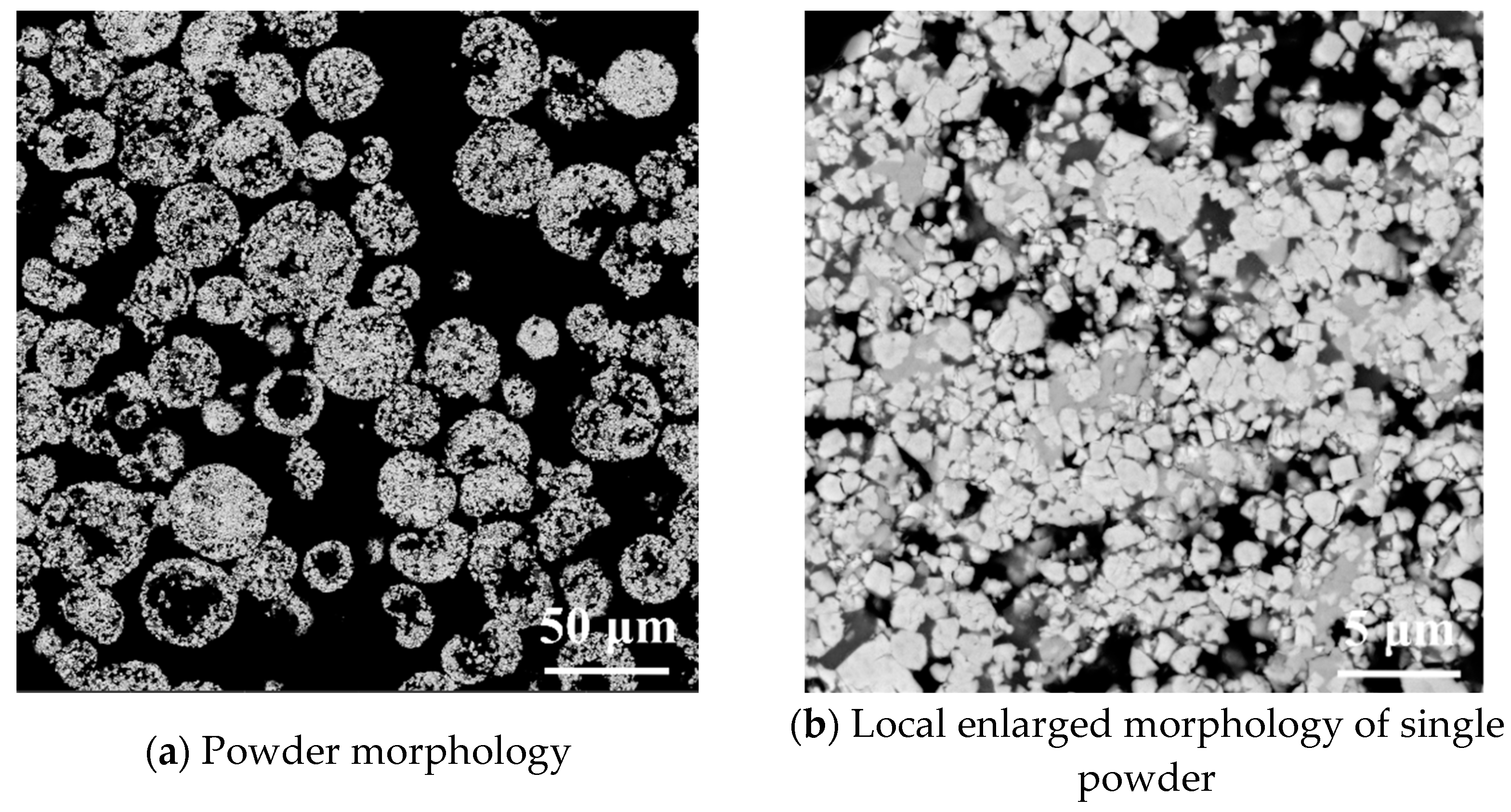
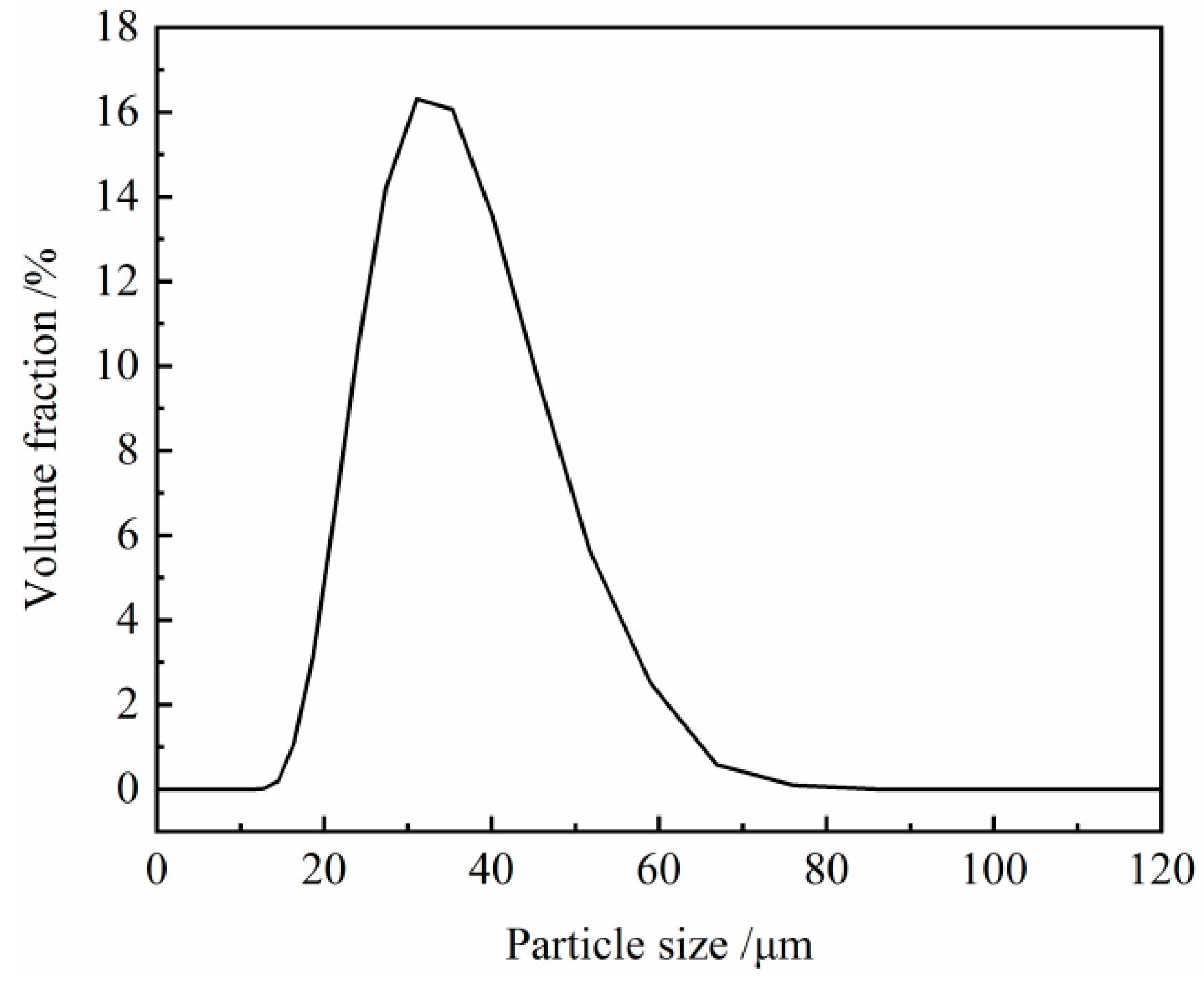
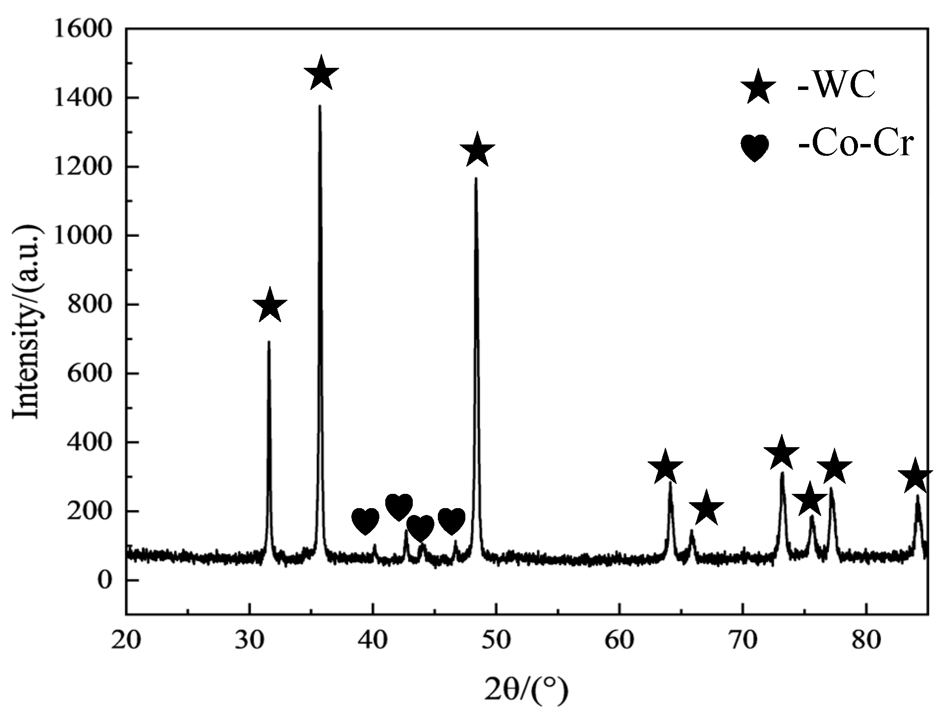
3.1. Powder Morphology and Performance Analysis

As shown in Figure 2a, the majority of the hard alloy powders exhibited a solid spherical morphology, while only a small fraction displayed a hollow spherical structure. This characteristic contributes to the good flowability of the powder, making it suitable for both plasma spraying and laser cladding. A closer examination of the cross-section of an individual powder particle is presented in Figure 2b. Each particle is composed of numerous agglomerated fine white particles, with a significant number of small pores present within the structure. This indicates that the strength of the powder particles is moderate, allowing for uniform heating during the plasma spraying or laser cladding processes. Such a feature is beneficial for achieving better deposition and forming a cohesive coating. Furthermore, the particle size and distribution of the hard alloy powder were measured using an LA-950 laser particle size analyzer, with the laser particle size distribution curve illustrated in Figure 3. The analysis revealed that the average particle diameter is approximately 32 μm, with the majority of the powder particles falling within the size range of 15–50 μm. This size range facilitates complete melting during the experimental processes, ensuring effective coating formation. Figure 4 is the XRD pattern of WC-10Co-4Cr powder. It can be concluded that the raw material powder is mainly in the WC phase.

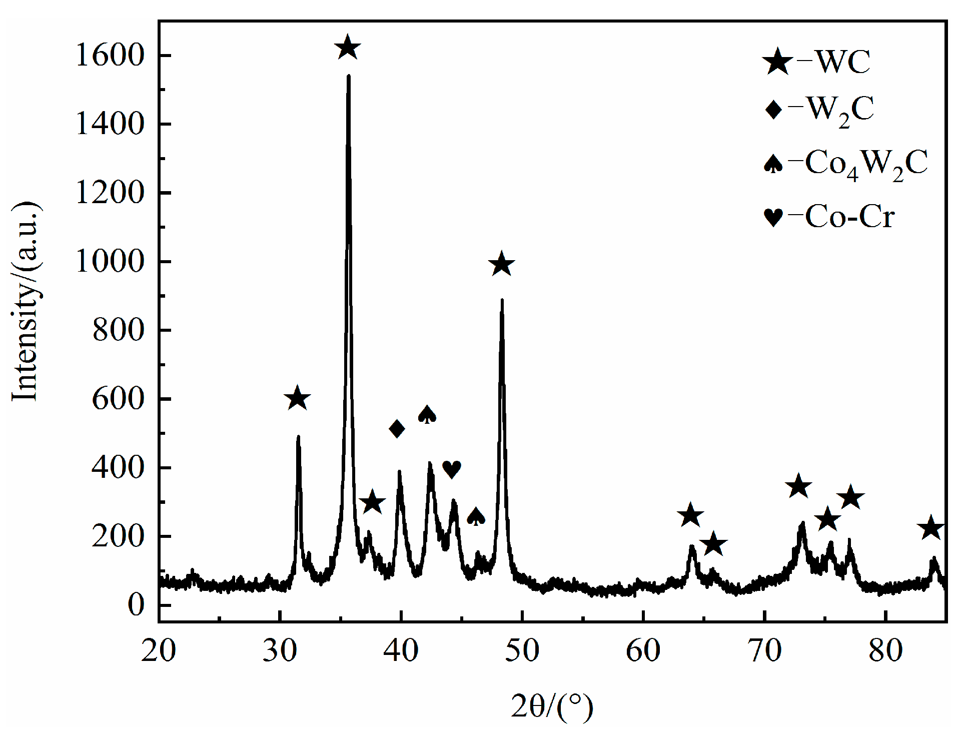
3.2. Microstructural and Phase Analysis of Coatings

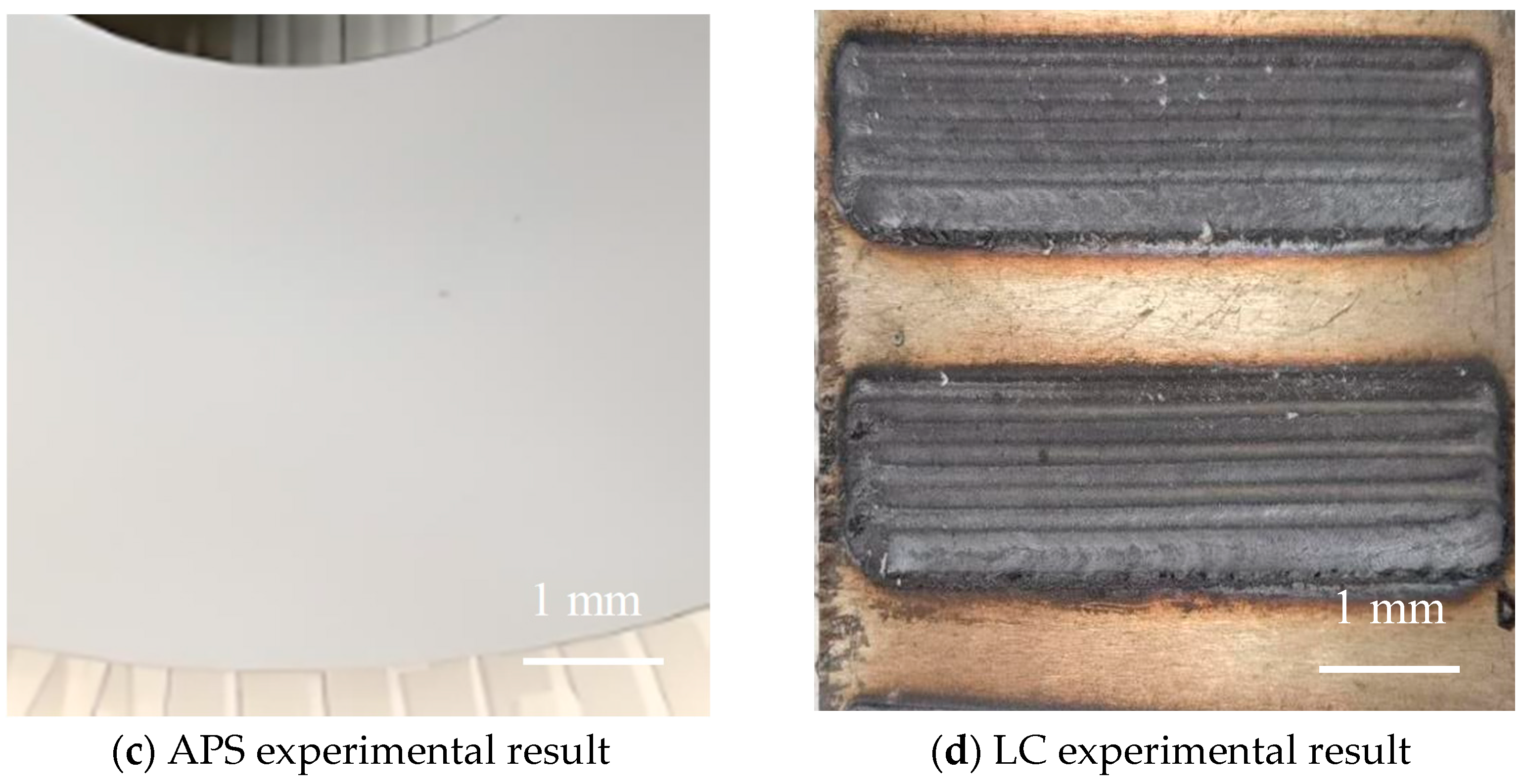
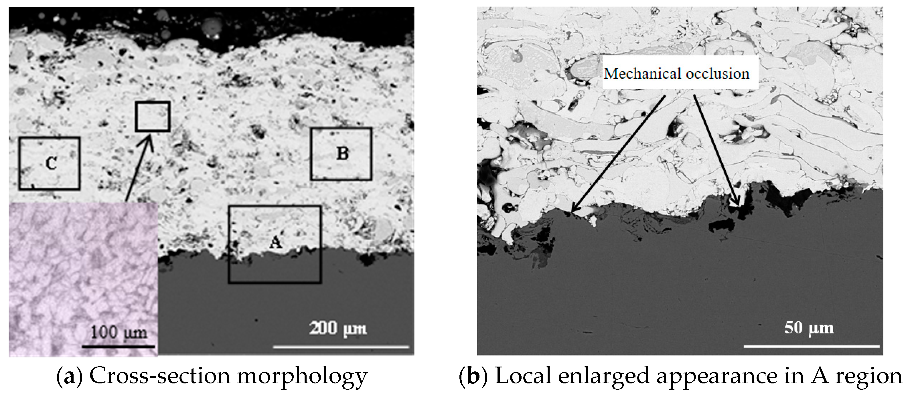
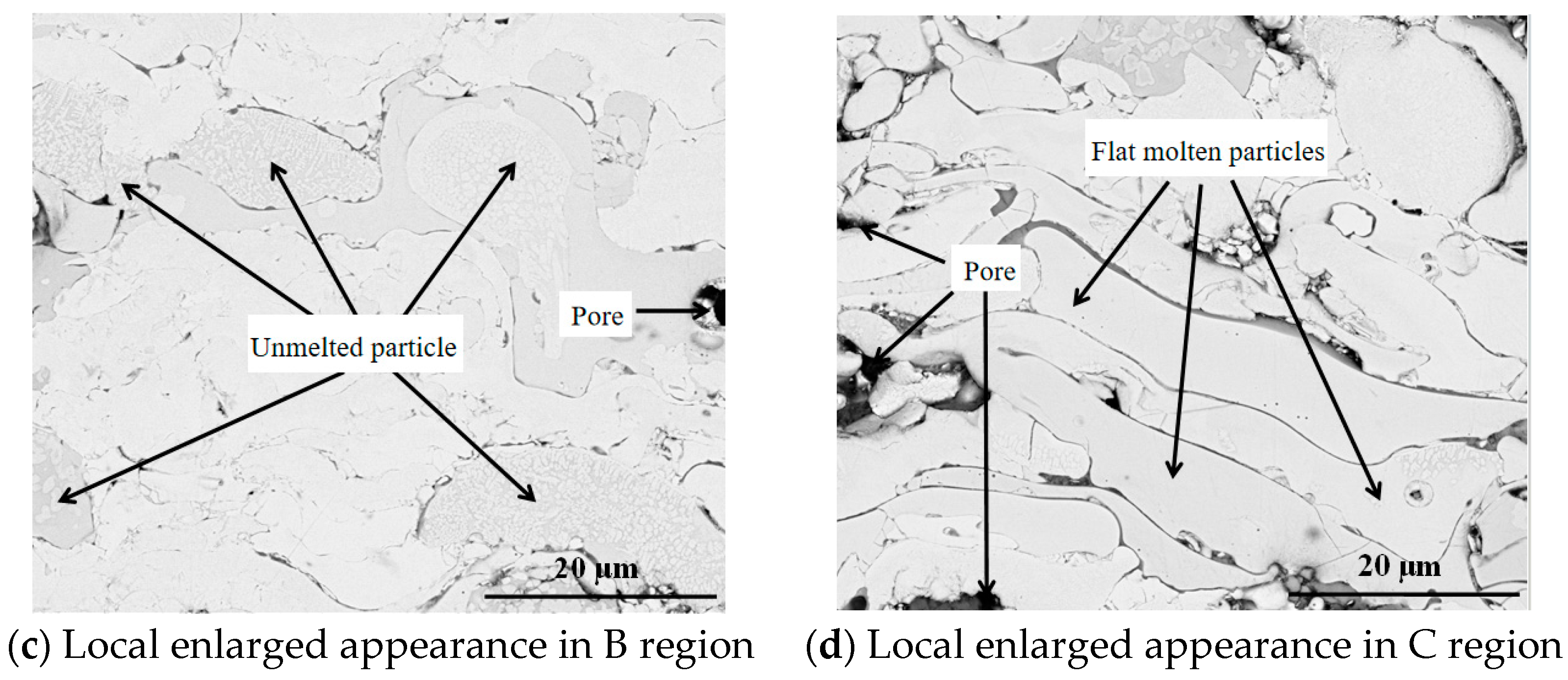
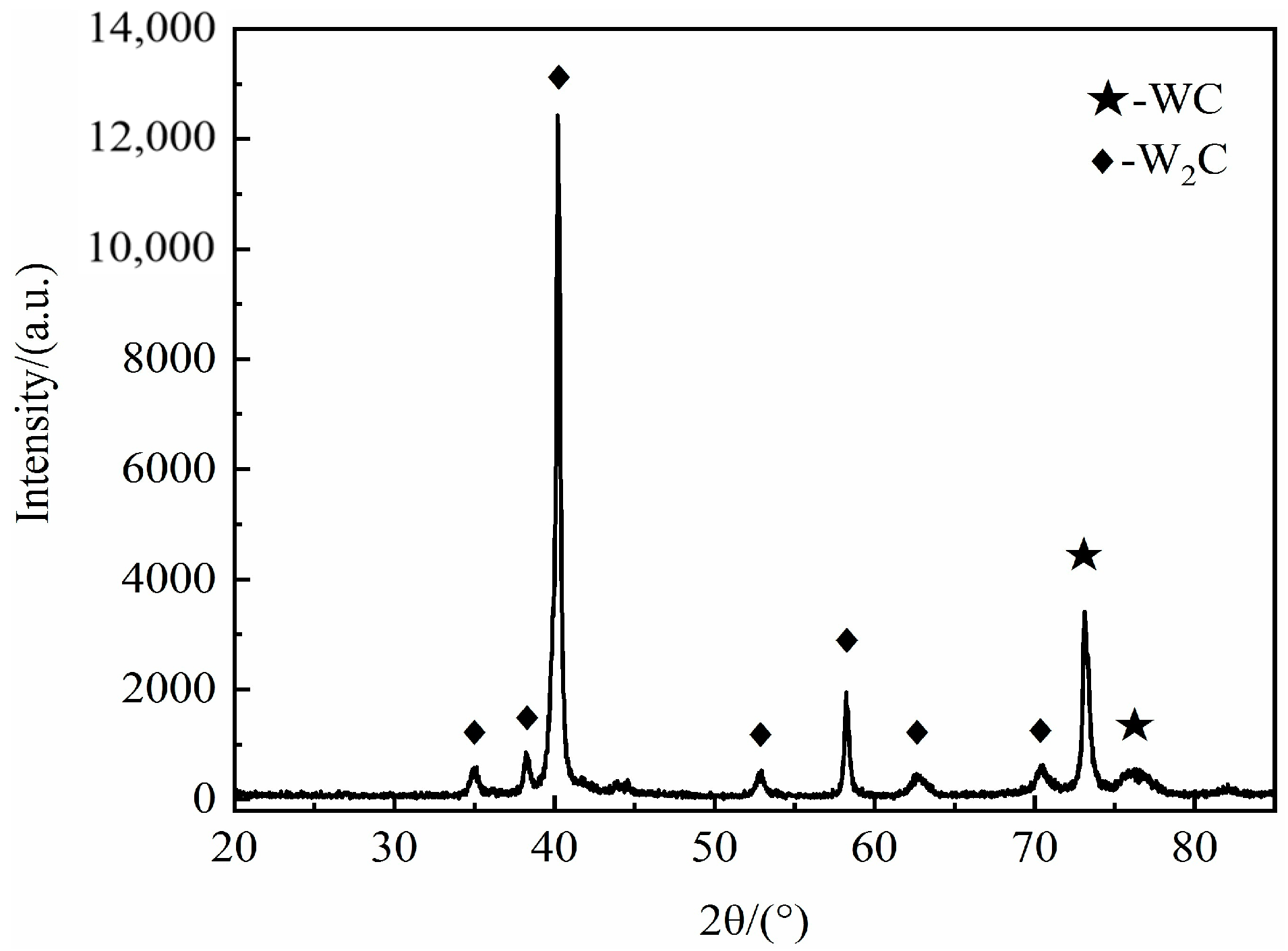
3.2.1. Microstructural and Phase Analysis of APS Coatings

The microstructure of the atmospheric plasma sprayed (APS) coating was analyzed using a field emission scanning electron microscope (FE-SEM). The cross-sectional morphology of the coating is illustrated in Figure 5a, which reveals that the WC-10Co-4Cr coating has a thickness of approximately 500 μm on the surface of the 304 stainless steel substrate. The interface between the coating and the substrate exhibits clear mechanical interlocking, with no visible porosity or cracks observed at the bonding interface, as shown in Figure 5b. Black particles are noticeable within the 304 stainless steel substrate, particularly in the region near the bonding interface; these particles are attributed to the embedding of Al2O3 abrasive particles into the surface of the stainless steel during the sandblasting process. Figure 5c presents a localized magnified view of the coating’s interior, where several partially melted metallic powder particles can be observed. This phenomenon occurs because, during the APS process, the surface of larger particles experiences melting, while the central regions remain incompletely heated and melted, resulting in the retention of unmolten metallic powder particles within the coating. Furthermore, a classic lamellar structure is evident in the coating, as illustrated in Figure 5d. This structure is primarily composed of flattened molten particles, which form due to the melting and impact of the powder particles against the substrate during the spraying process. Subsequently, as the coating cools and solidifies, it undergoes deformation and stacking, leading to the final formation of the layered structure [20].
As illustrated in Figure 6, the XRD pattern of the APS coating predominantly exhibits diffraction peaks corresponding to the W2C phase, with supplementary peaks attributed to the WC phase. Compared with Figure 4, the high thermal energy generated during the APS process facilitates the rapid decarburization of WC, leading to the formation of W2C. Ding et al. [22] prepared a coating on 304 stainless steel using HVOF. The carbide was mainly WC, and there was no obvious decarburization of WC. This finding aligns with the research conclusions of Hou [23].

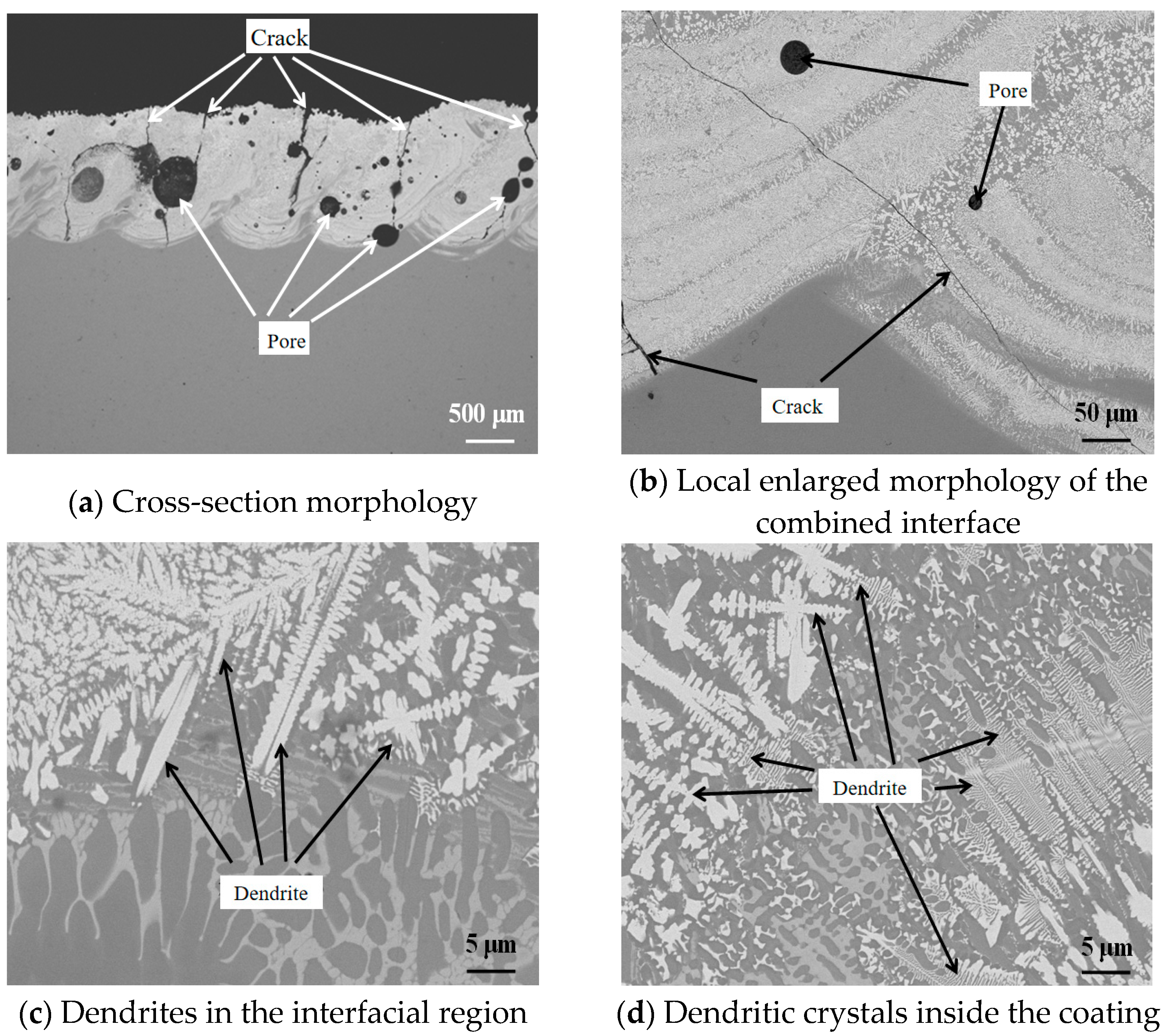
3.2.2. Microstructural and Phase Analysis of LC Coatings

The cross-sectional morphology of the laser-clad (LC) coating is illustrated in Figure 7a,b. The LC coating exhibits a thickness greater than 1 mm, with a tightly bonded interface to the substrate that reflects a metallurgical bonding morphology. Generally, metallurgical bonding is more robust than mechanical bonding, indicating that the WC-10Co-4Cr coating produced by LC possesses a higher interface bonding strength with the substrate compared to the WC-10Co-4Cr coating fabricated by APS. Figure 7c,d show a significant presence of dendritic structures within the coating. Numerous large gas pores and cracks are observed, which arise from the rapid melting and cooling of powder particles under the influence of high laser energy. The retention of gas within the molten pool, which was not promptly expelled, results in the formation of gas pores, while the cracks are primarily due to excessive thermal stress leading to coating failure. As the distance from the laser head increases, the amount of heat received diminishes; thus, a temperature gradient exists perpendicular to the coating surface during its formation. Consequently, crystal growth preferentially occurs in this direction, while lateral growth is relatively slower, ultimately resulting in the formation of dendritic structures characterized by a larger central region and shorter tips at both ends [24].
As shown in Figure 8, the XRD pattern of the LC coating primarily features diffraction peaks corresponding to the WC phase, with supplementary peaks from W2C, Co4W2C, and CoCr phases. Research by Shi [16] indicates that, during the laser cladding process, a small amount of WC undergoes decarburization and decomposition to form W2C. Additionally, the WC-10Co-4Cr powder decomposes into solid and liquid phases, where the liquid Co combines with solid W2C to form Co4W2C. Compared with Figure 6, it can be observed that the APS coating is mainly composed of the W2C phase, while the LC coating is mainly composed of the WC phase. This indicates that the temperature generated during the APS process is higher, which promotes the decomposition of WC. This observation suggests that the extent of WC phase decomposition in the LC coating is lower than that in the APS coating.

3.3. Mechanical Properties Analysis of the Coatings

The hardness results of the coatings prepared by APS and LC are shown in Table 3. The average hardness of the coating prepared by LC (1440.5 HV) is greater than that of the coating prepared by APS (1341.7 HV). Moreover, the σ of the coating prepared by LC is smaller. This indicates that the coating prepared by LC not only has high hardness but also a uniform distribution. It can be observed that the hardness values of the APS coating are lower than those of the LC coating. This discrepancy can be attributed primarily to the high thermal energy of the plasma arc during the formation of the APS coating, which leads to the decomposition of the hard WC phase in the powder into W2C and other substances, thereby directly reducing the overall hardness of the coating. Conversely, the LC coating, which solidifies rapidly to form a dendritic structure, exhibits significantly higher hardness than the APS coating. Thus, it can be concluded that higher material hardness correlates with improved wear resistance. Table 4 shows the comparison of coating hardness under different processes. As can be seen from Table 4, the coating prepared by LC has a relatively high hardness. The hardness of the WC-10Co-4Cr coatings prepared in this study is higher than that of the coatings prepared by HVOF mentioned in the literature. This indicates that the processes used in this study have certain guiding significance for the preparation of WC-10Co-4Cr coatings.
Figure 9 shows the variation of the friction coefficients of the substrate and the coatings with time. It can be observed that, in the initial stage of the friction test, both the substrate and the coatings exhibit a stage where the friction coefficient increases rapidly, and then it decreases to a stable state. Compared with the substrate, both the APS coating and the LC coating demonstrate excellent wear resistance. The friction coefficient of the APS coating gradually stabilized after approximately 8 min, while that of the LC coating stabilized after just 2.5 min. This initial period of run-in is primarily determined by the structural uniformity within the coatings; the more uniform the internal structure, the quicker and more stable the friction process becomes [28]. Therefore, it can be concluded that the structural uniformity of the LC coating is superior to that of the APS coating. After entering the stable friction state, the friction coefficient of the APS coating is approximately 0.45, while that of the LC coating stabilizes at around 0.4, indicating less wear of the LC coating. Further mass-loss tests show that the mass loss of the APS coating after wear is approximately 0.005 g, while that of the LC coating is approximately 0.002 g, confirming that the wear resistance of the LC coating is higher than that of the APS coating. Ceviz et al. [29] prepared WC-10Co-4Cr coatings on AA7075-T6 substrates by HVOF. The friction coefficient of the coatings at 200 °C was approximately 0.48. This further demonstrates that the WC-10Co-4Cr coatings prepared by LC in this paper possess excellent wear resistance.
As shown in Figure 10a,b, the APS coating exhibited a significant amount of fragmented particles on the surface after wear, with extensive wear pits exposing the underlying coating. In contrast, Figure 10c,d demonstrate that the LC-produced WC-10Co-4Cr coating, after wear, exhibited only a few cracks (which were formed during the laser cladding process) along with a large number of fine particles; however, the overall structure remained relatively intact, showing a more uniform wear pattern. These observations indicate that the LC coating demonstrates greater resistance to fatigue failure during prolonged friction wear compared to the APS coating, thus reducing the likelihood of extensive layer spalling. Therefore, it can be concluded that the LC coating possesses superior wear resistance compared to the APS coating. This conclusion is consistent with the previous analyses of the friction coefficient curves and mass loss, further enhancing the accuracy of the findings presented in this study.
In the APS coating, it was observed that, during the wear process, larger grains broke, producing finer grains with stronger cutting and plowing abilities. As the wear process advanced, these broken fine particles were prone to embedding in the friction pair, increasing the friction coefficient between the coating and the friction pair. This generated higher heat and pressure in local areas, exacerbating the wear of both the coating and the friction pair, resulting in the coating pits and adhesive wear areas shown in Figure 10a. On the other hand, the LC coating had a refined microstructure formed by rapid cooling. During the wear process, the fine grains underwent continuous wear, forming a flat wear surface (Figure 10c), which gave it a more stable friction coefficient curve (Figure 9) and friction coefficient value. As can be seen from Figure 10d, the grain size distribution of the LC coating was concentrated, all presenting typical abrasive wear morphologies, without characteristics of grain breakage and adhesive wear. Therefore, the wear mechanisms of the coatings prepared by the two processes can be summarized as follows: the LC coating undergoes abrasive wear; the APS coating is subject to a combined effect of abrasive wear and adhesive wear, with abrasive wear being the main wear mechanism.

4. Conclusions

  • In this study, WC-10Co-4Cr hard alloy coatings were successfully fabricated on the surfaces of 304 and 316 stainless steel substrates using APS and LC technologies. The LC coating displayed a dendritic structure with a metallurgical bonding interface, in-dicating the LC coating has a superior bonding effect with the substrate. The lower de-gree of WC phase decomposition compared to the APS coating contributes positively to the enhancement of coating strength.
  • The average micro-Vickers hardness of the APS coating and the LC coating is 1341.7 HV and 1440.5 HV, respectively. The micro-Vickers hardness of the LC coating is 7% higher than that of the APS coating.
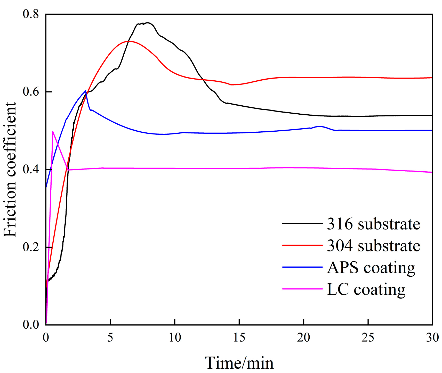
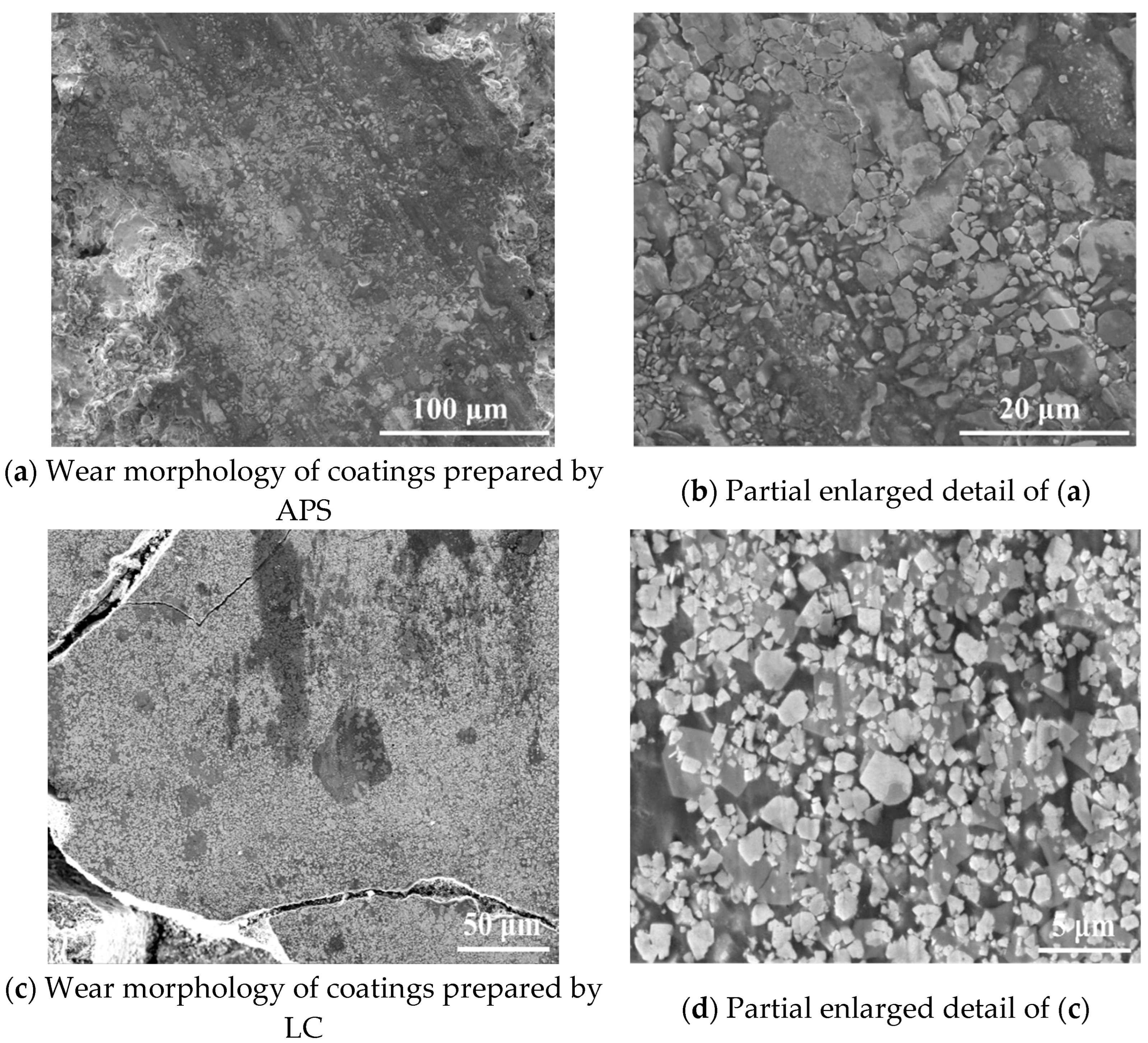
  • During the wear test of the APS coating, the friction coefficient was approximately 0.45 and the mass loss was 0.005 g. A large number of wear particles and spalling pits appeared on the worn surface of the APS coating, exposing the underlying structure of the coating. In contrast, for the LC coating, the friction coefficient was approximately 0.4 and the mass loss was 0.002 g. The wear surface of the LC coating displayed nu-merous wear particles along with a few microcracks, demonstrating a uniform wear pattern without extensive spalling. These results indicate that the WC-10Co-4Cr coat-ing produced by LC exhibits superior mechanical properties, thereby meeting the re-quirements for more demanding service conditions.

Author Contributions

Conceptualization, Z.G.; Methodology, Z.G.; Validation, Y.W.; Investigation, Y.W.; Resources, F.L. and Y.W.; Writing—original draft, Z.G.; Writing—review & editing, F.L. All authors have read and agreed to the published version of the manuscript.

Funding

This research received no external funding.

Data Availability Statement

The original contributions presented in this study are included in the article. Further inquiries can be directed to the corresponding author.

Conflicts of Interest

Author “Zhanji Geng” was employed by Changsha Huaxi New Material Co., Ltd. The remaining authors declare that the research was conducted in the absence of any commercial or financial relationships that could be construed as a potential conflict of interest.

References

  1. Yadav, S.; Zhang, Q.; Behera, A.; Haridas, R.S.; Agrawal, P.; Gong, J.; Mishra, R.S. Role of Binder Phase on the Microstructure and Mechanical Properties of a Mechanically Alloyed and Spark Plasma Sintered WC-FCC HEA Composites. J. Alloys Compd. 2021, 877, 160265. [Google Scholar] [CrossRef]
  2. Chang, L.; Wang, W.; Ma, D.; Xie, J. Deposition Effects and Interface Structure of HVOF-Sprayed Multimodal WC-CoCr Coatings. J. Mater. Res. 2023, 38, 4345–4356. [Google Scholar] [CrossRef]
  3. Suresh Babu, P.; Madhavi, Y.; Rama Krishna, L.; Srinivasa Rao, D.; Padmanabham, G. Thermally-Sprayed WC-Based Cermet Coatings for Corrosion Resistance Applications. JOM 2018, 70, 2636–2649. [Google Scholar] [CrossRef]
  4. Hu, Q.; Ji, D.; Shen, M.; Zhuang, H.; Yao, H.; Zhao, H.; Guo, H.; Zhang, Y. Three-Body Abrasive Wear Behavior of WC-10Cr3C2-12Ni Coating for Ball Mill Liner Application. Materials 2022, 15, 4569. [Google Scholar] [CrossRef]
  5. Wang, Q.; Zhong, Y.; Li, H.; Wang, S.; Liu, J.; Wang, Y.; Ramachandran, C.S. Effect of Cobalt and Chromium Content on Microstructure and Properties of WC-Co-Cr Coatings Prepared by High-Velocity Oxy-Fuel Spraying. Materials 2023, 16, 7003. [Google Scholar] [CrossRef]
  6. Matikainen, V.; Koivuluoto, H.; Vuoristo, P.; Schubert, J. Effect of Nozzle Geometry on the Microstructure and Properties of HVAF-Sprayed WC-10Co4Cr and Cr3C2-25NiCr Coatings. J. Therm. Spray Technol. 2018, 27, 680–694. [Google Scholar] [CrossRef]
  7. Liu, S.; Ma, X.; Zhen, X.; Wang, F.; Liu, Y.; Meng, Q. Effect of WC-10Co-4Cr Reinforcement Amount on Wear and Corrosion Resistance of Fe-Based Amorphous Coatings. J. Therm. Spray Technol. 2024, 33, 1601–1611. [Google Scholar] [CrossRef]
  8. Picas, J.A.; Punset, M.; Rupérez, E.; Menargues, S.; Martin, E.; Baile, M.T. Corrosion Mechanism of HVOF Thermal Sprayed WC-CoCr Coatings in Acidic Chloride Media. Surf. Coat. Technol. 2019, 371, 378–388. [Google Scholar] [CrossRef]
  9. Cui, S.; Miao, Q.; Xu, Y.; Li, B. Comparative Analysis of Tribological Behavior of Plasma- and High-Velocity Oxygen Fuel-Sprayed WC-10Co-4Cr Coatings | Emerald Insight. Ind. Lubr. Tribol. 2017, 69, 325–332. [Google Scholar] [CrossRef]
  10. Xi, H.; He, P.; Wang, H.; Liu, M.; Chen, S.; Xing, Z.; Ma, G.; Lv, Z. Microstructure and Mechanical Properties of Mo Coating Deposited by Supersonic Plasma Spraying. Int. J. Refract. Met. Hard Mater. 2020, 86, 105095. [Google Scholar] [CrossRef]
  11. Liang, X.; Zhuang, T.; Lan, L.; Huang, J.; Li, S.; Lei, Y.; Xu, B.; Wang, Y.; Shi, X.; Hu, Q. Study on Wear and Scour Performance of Ni6035WC/Wc-10Cr-4Cr Coating by HVAF. Coatings 2024, 14, 1148. [Google Scholar] [CrossRef]
  12. Yin, M.; Shao, Y.; Kang, X.; Long, J.; Zhang, X. Fretting Corrosion Behavior of WC-10Co-4Cr Coating on Inconel 690 Alloy by HVOF Thermal Spraying. Tribol. Int. 2023, 177, 107975. [Google Scholar] [CrossRef]
  13. Hong, S.; Wu, Y.; Zhang, J.; Zheng, Y.; Qin, Y.; Lin, J. Ultrasonic Cavitation Erosion of High-Velocity Oxygen-Fuel (HVOF) Sprayed near-Nanostructured WC–10Co–4Cr Coating in NaCl Solution. Ultrason. Sonochem. 2015, 26, 87–92. [Google Scholar] [CrossRef]
  14. Angelastro, A.; Campanelli, S.L.; Casalino, G.; Ludovico, A.D. Optimization of Ni-Based WC/Co/Cr Composite Coatings Produced by Multilayer Laser Cladding. Adv. Mater. Sci. Eng. 2013, 2013, 615464. [Google Scholar] [CrossRef]
  15. López-Baltazar, E.A.; Ruiz-Luna, H.; Baltazar-Hernández, V.H.; Ruiz-Mondragón, J.J.; Ibarra-Medina, J.; Alvarado-Orozco, J.M. Effect of the Average Energy on WC Grain Growth of WC-10Co-4Cr Composite by Laser Cladding. Metals 2019, 9, 1245. [Google Scholar] [CrossRef]
  16. Shi, J.; Ge, Y.; Kong, D. Microstructure, Dry Sliding Friction Performances and Wear Mechanism of Laser Cladded WC–10Co4Cr Coating with Different Al2O3 Mass Fractions. Surf. Coat. Technol. 2021, 406, 126749. [Google Scholar] [CrossRef]
  17. Jiangzheng, S.; Dejun, K. Effects on Al2O3 and La2O3 Additions on Electrochemical Performances of Laser-Cladded WC10Co4Cr Coatings. Int. J. Appl. Ceram. Technol. 2022, 19, 436–450. [Google Scholar] [CrossRef]
  18. Khanna, A.S.; Kumari, S.; Kanungo, S.; Gasser, A. Hard Coatings Based on Thermal Spray and Laser Cladding. Int. J. Refract. Met. Hard Mater. 2009, 27, 485–491. [Google Scholar] [CrossRef]
  19. Naghiyan Fesharaki, M.; Shoja-Razavi, R.; Mansouri, H.A.; Jamali, H. Microstructure Investigation of Inconel 625 Coating Obtained by Laser Cladding and TIG Cladding Methods. Surf. Coat. Technol. 2018, 353, 25–31. [Google Scholar] [CrossRef]
  20. Geng, Z.; Zhang, M.; Zhu, J.; Peng, Y.; Zhang, W.; Liu, F. Effect of Chromium Carbide Addition on the Microstructures and Properties in Dual Carbide Phases Reinforced Ni-Based Composite Coatings by Plasma Cladding. Materials 2023, 16, 4580. [Google Scholar] [CrossRef]
  21. Fernández, M.R.; García, A.; Cuetos, J.M.; González, R.; Noriega, A.; Cadenas, M. Effect of Actual WC Content on the Reciprocating Wear of a Laser Cladding NiCrBSi Alloy Reinforced with WC. Wear 2015, 324–325, 80–89. [Google Scholar] [CrossRef]
  22. Ding, X.; Cheng, X.; Yu, X.; Li, C.; Yuan, C.; Ding, Z. Structure and Cavitation Erosion Behavior of HVOF Sprayed Multi-Dimensional WC–10Co4Cr Coating. Trans. Nonferrous Met. Soc. China 2018, 28, 487–494. [Google Scholar] [CrossRef]
  23. Hou, G.; An, Y.; Liu, G.; Zhou, H.; Chen, J.; Chen, Z. Effect of Atmospheric Plasma Spraying Power on Microstructure and Properties of WC-(W,Cr)2C-Ni Coatings. J. Therm. Spray Technol. 2011, 20, 1150–1160. [Google Scholar] [CrossRef]
  24. Wang, Z.; Tan, M.; Wang, J.; Zeng, J.; Zhao, F.; Xiao, X.; Xu, S.; Liu, B.; Gong, L.; Sui, Q.; et al. Core-Shell Structural Iron Based Metal Matrix Composite Powder for Laser Cladding. J. Alloys Compd. 2021, 878, 160127. [Google Scholar] [CrossRef]
  25. Biswas, K.; Sahoo, C.K. The Performance Evaluation of WC/Co-Cr Coating for Developing Hard, Wear, and Corrosion Resistance Surface Using TIG Arc Source. Int. J. Refract. Met. Hard Mater. 2025, 128, 106983. [Google Scholar] [CrossRef]
  26. Murugan, K.; Ragupathy, A.; Balasubramanian, V.; Sridhar, K. Optimizing HVOF Spray Process Parameters to Attain Minimum Porosity and Maximum Hardness in WC–10Co–4Cr Coatings. Surf. Coat. Technol. 2014, 247, 90–102. [Google Scholar] [CrossRef]
  27. Prasad, R.V.; Rajesh, R.; Thirumalaikumarasamy, D.; Vignesh, S.; Sreesabari, S. Sensitivity Analysis and Optimisation of HVOF Process Inputs to Reduce Porosity and Maximise Hardness of WC-10Co-4Cr Coatings. Sādhanā 2021, 46, 149. [Google Scholar] [CrossRef]
  28. Vaz, R.F.; Silvello, A.; Albaladejo, V.; Sanchez, J.; Cano, I.G. Improving the Wear and Corrosion Resistance of Maraging Part Obtained by Cold Gas Spray Additive Manufacturing. Metals 2021, 11, 1092. [Google Scholar] [CrossRef]
  29. Ceviz, M.; Misirli, C.; Karabeyoglu, S.S. The Effect of Temperature on Wear Performance of High-Velocity Oxy-Fuel Sprayed WC-10Co-4Cr Coating on AA7075-T6 Substrate. J. Mater. Eng. Perform. 2022, 31, 128–138. [Google Scholar] [CrossRef]
Figure 1. Preparation test of WC-10Co-4Cr coating.
Metals 15 00309 g001aMetals 15 00309 g001b
Figure 2. SEM images of WC-10Co-4Cr powder cross-section.
Metals 15 00309 g002
Figure 3. Particle size distribution of WC-10Co-4Cr powder.
Metals 15 00309 g003
Figure 4. XRD of WC-10Co-4Cr powder.
Metals 15 00309 g004
Figure 5. Section morphology of WC-10Co-4Cr carbide coating prepared by APS.
Metals 15 00309 g005aMetals 15 00309 g005b
Figure 6. XRD pattern of coatings prepared by APS.
Metals 15 00309 g006
Figure 7. Section morphology of WC-10Co-4Cr carbide coating prepared by LC.
Metals 15 00309 g007
Figure 8. XRD pattern of coatings prepared by LC.
Metals 15 00309 g008
Figure 9. Friction coefficient curves of coatings prepared by APS and LC.
Metals 15 00309 g009
Figure 10. Wear surface morphology of WC-10Co-4Cr coating.
Metals 15 00309 g010
Table 1. Chemical composition of coating materials used by APS and LC.
Element/wt.%CrCoWC
WC-10Co-4Cr powder4.288.3271.4915.91
Table 2. Chemical composition of substrates used by APS and LC.
Element/wt.%CSiMnPSNiCrMo
304 stainless steel≤0.08≤1.0≤2.0≤0.035≤0.0358.0~10.518.0~20.0-
316 stainless steel≤0.08≤1.0≤2.0≤0.035≤0.03510.0~14.016.0~18.02.0~3.0
Table 3. Hardness test results of coatings prepared by APS and LC.
HVAVG.σ
APS1341.7101.6
LC1440.554.4
Table 4. Comparison of Hardness among Different Processes.
TechniqueHVReferences
APS1341.7This work
LC1440.5This work
TIG1200[25]
APS923[9]
LC1193[15]
HVOF1250[5]
HVOF1318[26]
HVOF1325[27]
Disclaimer/Publisher’s Note: The statements, opinions and data contained in all publications are solely those of the individual author(s) and contributor(s) and not of MDPI and/or the editor(s). MDPI and/or the editor(s) disclaim responsibility for any injury to people or property resulting from any ideas, methods, instructions or products referred to in the content.

