
Modification of Desulfurization Slag for Hot Metal Bearing V-Ti and Industry Application


Abstract
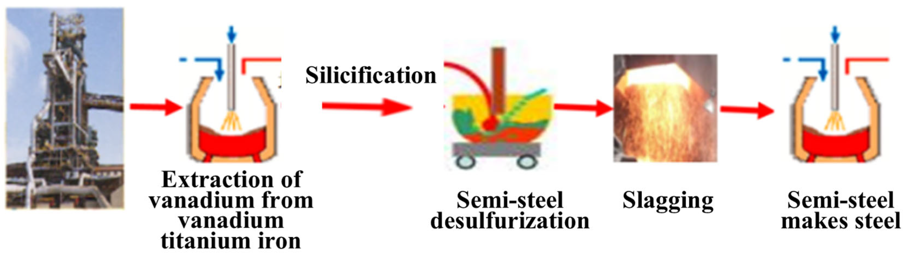
1. Introduction
2. Experimental
3. Results and Discussion
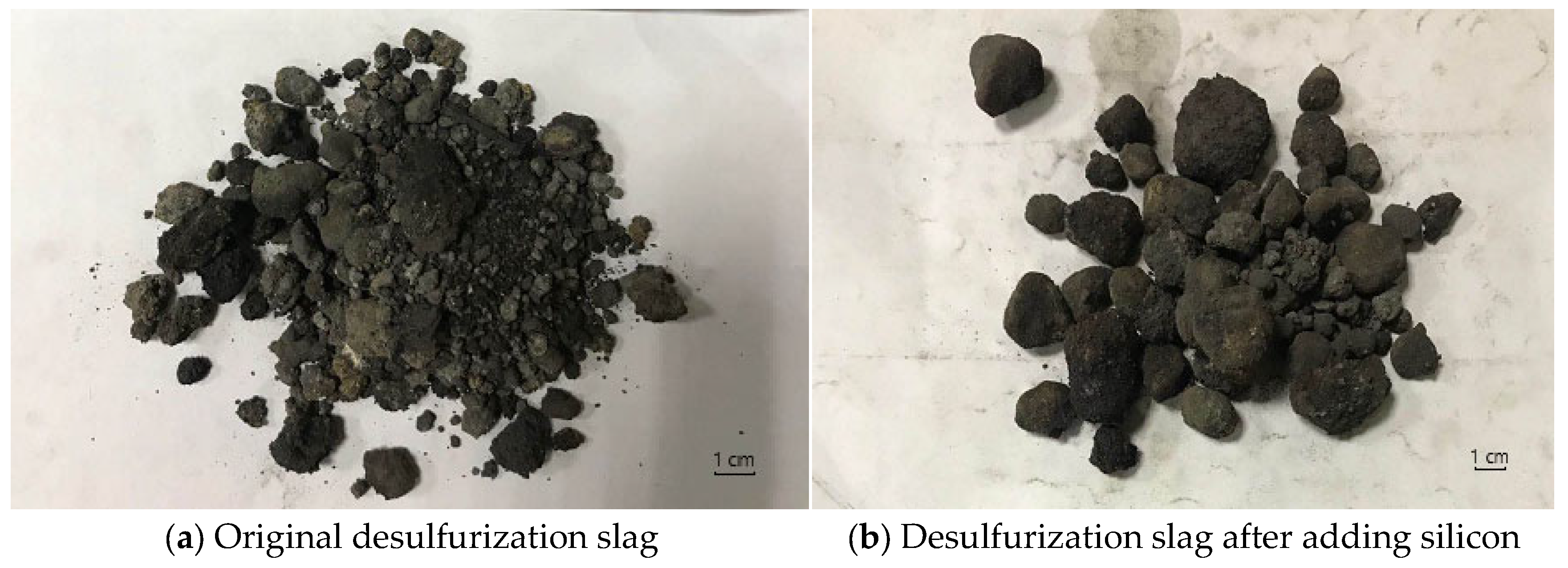
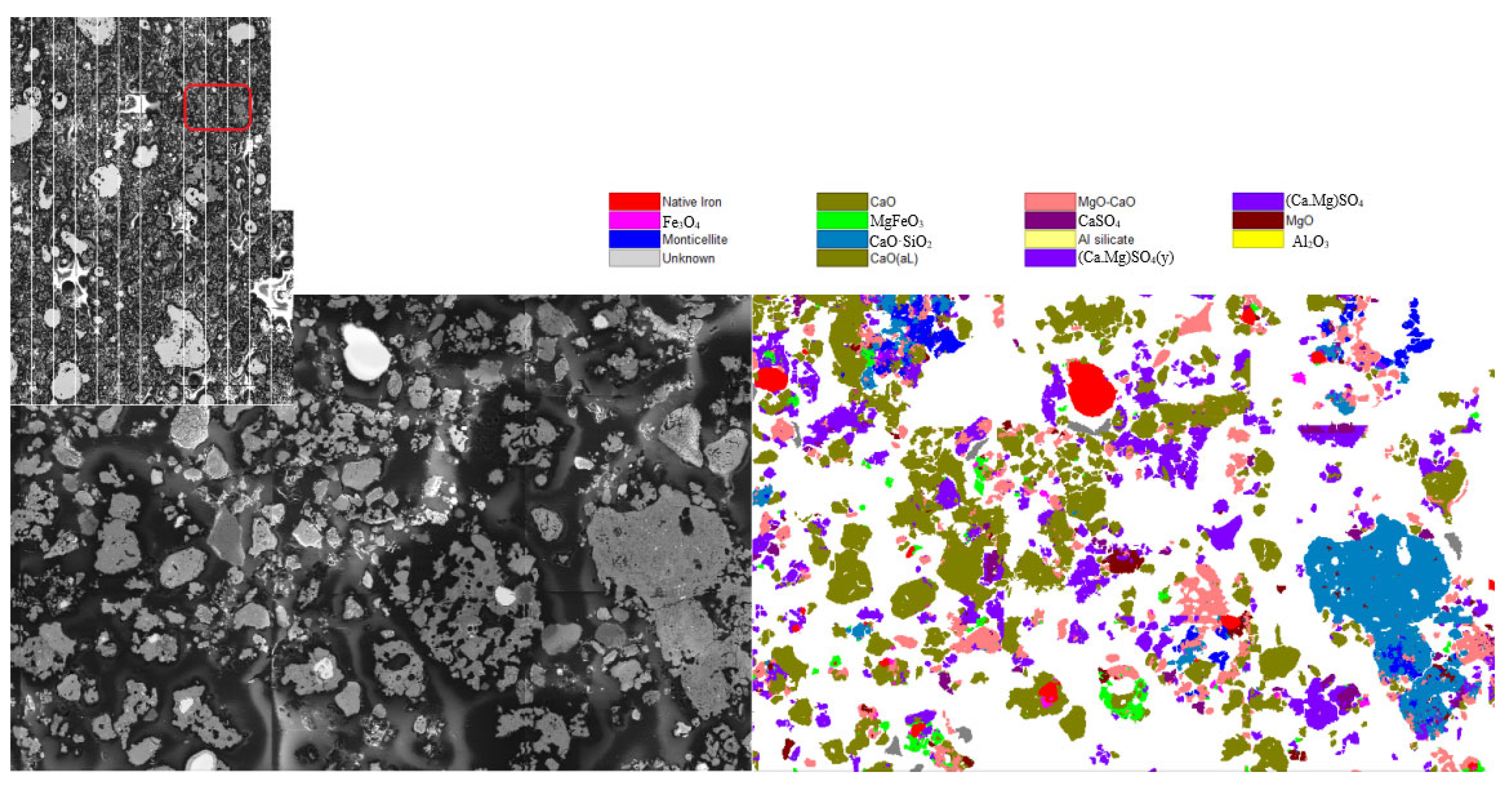
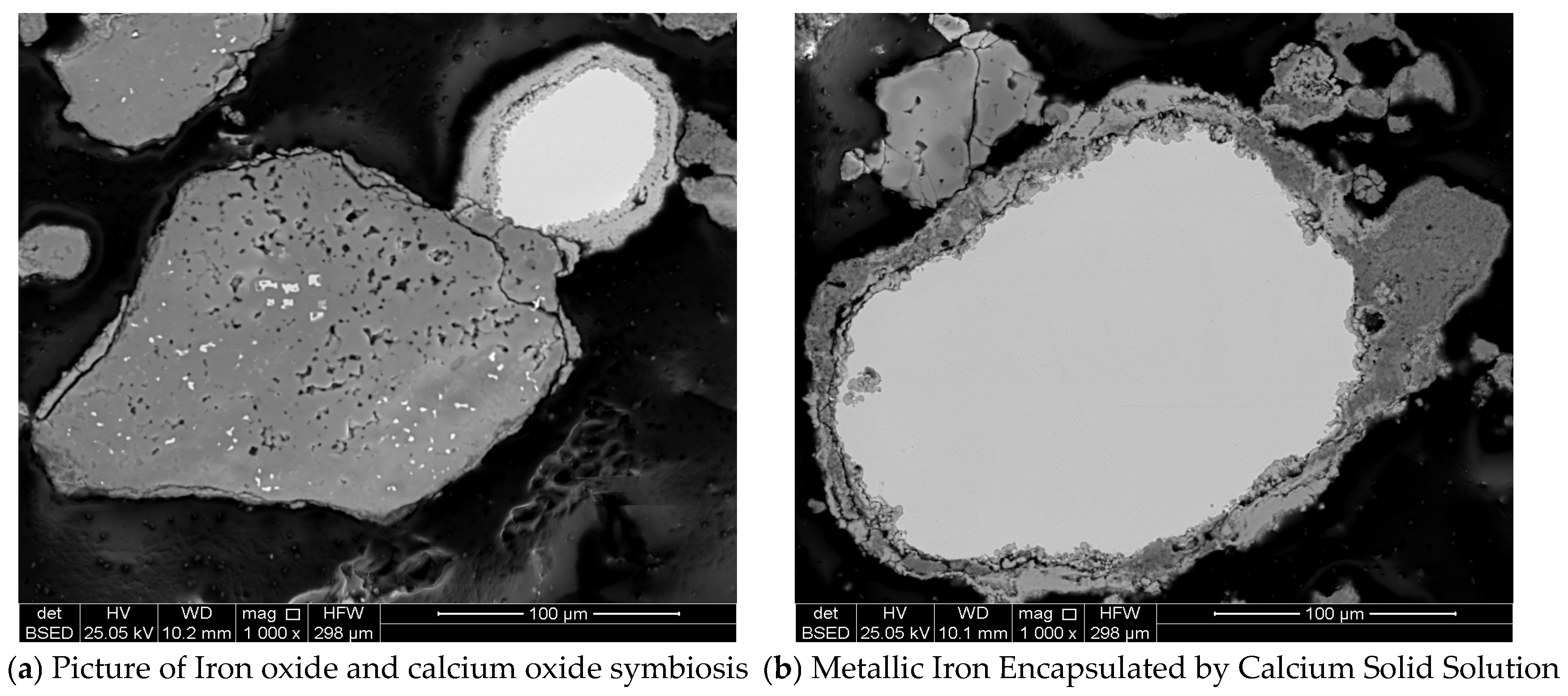
3.1. Original Desulphurization Slag
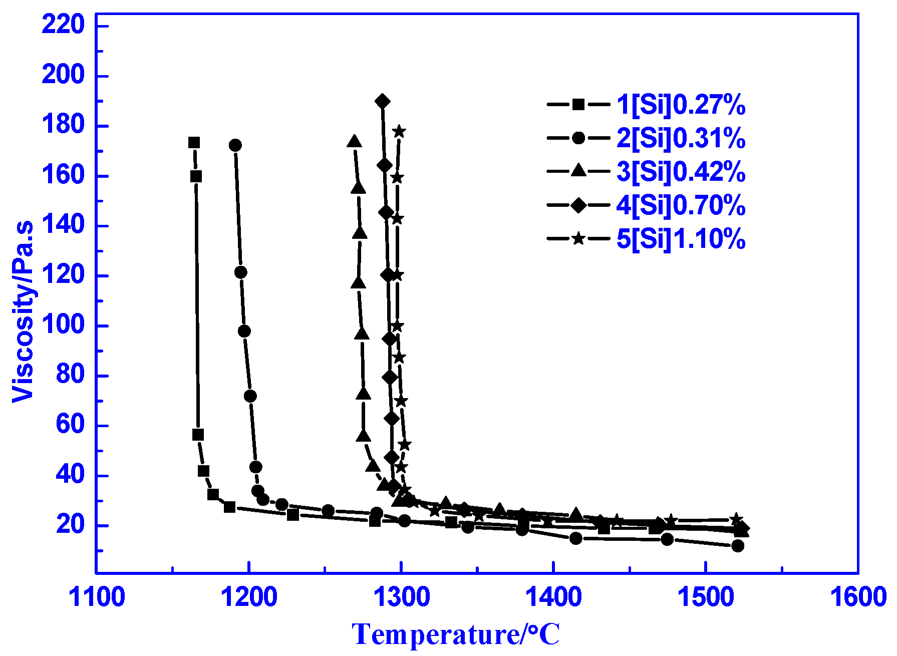
3.2. Suitable Silicon Content in Semi-Steel
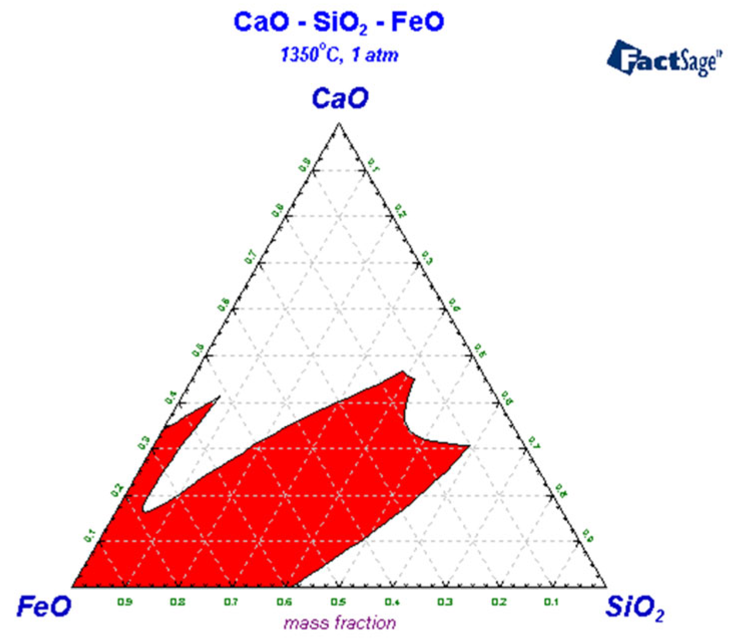
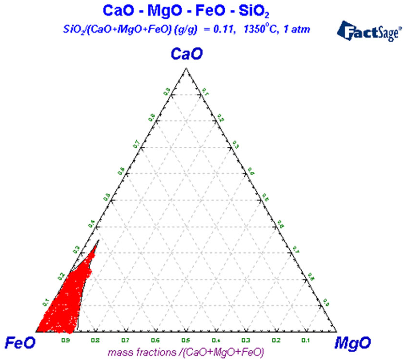
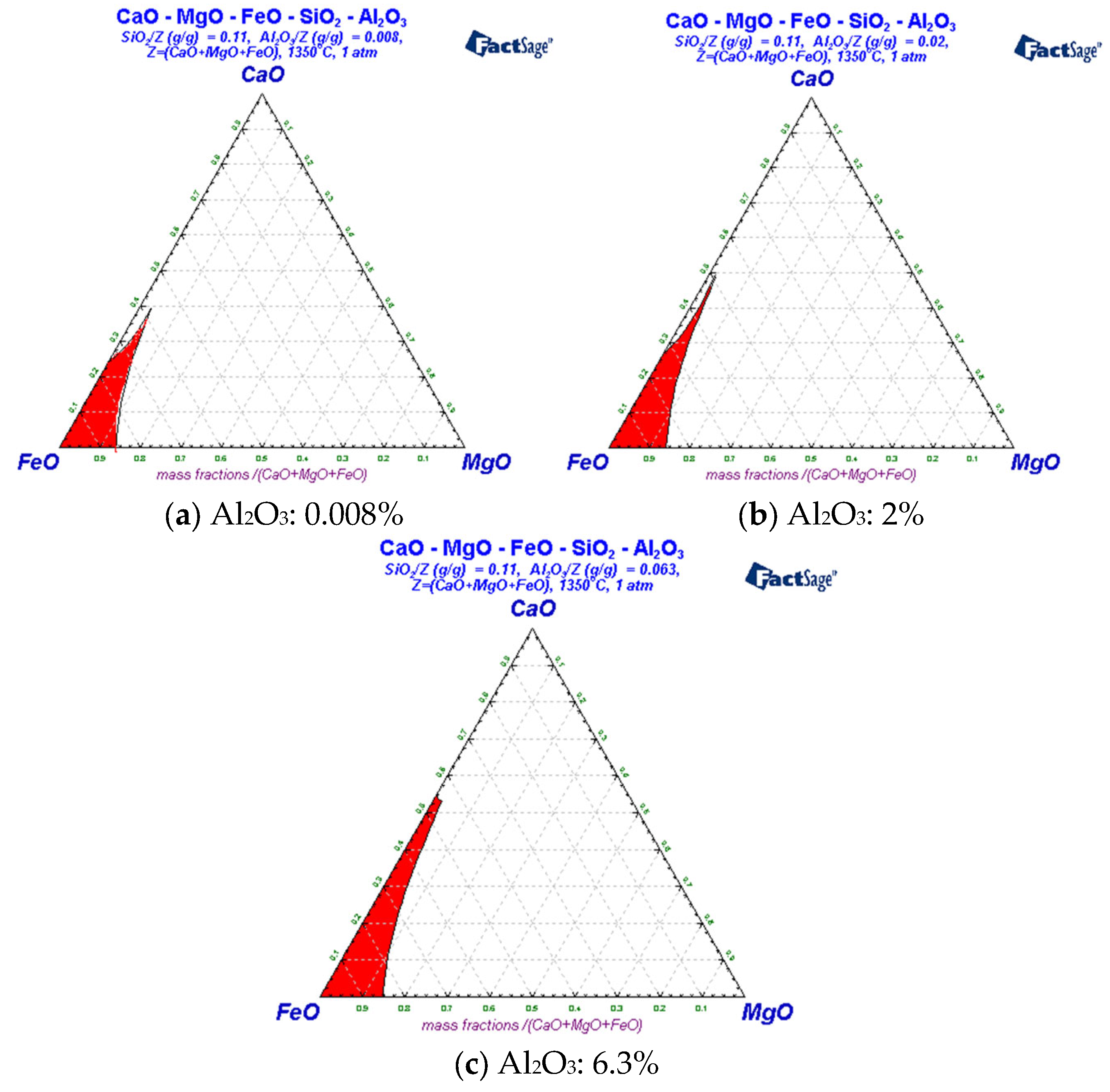
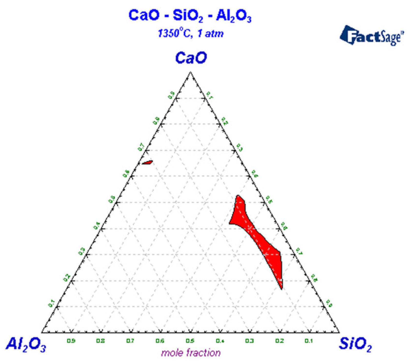
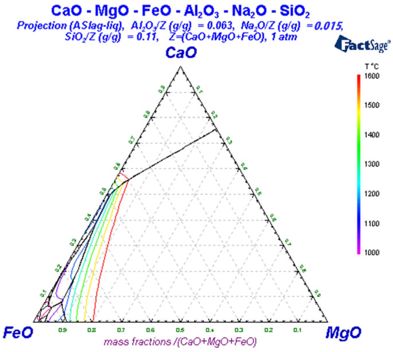
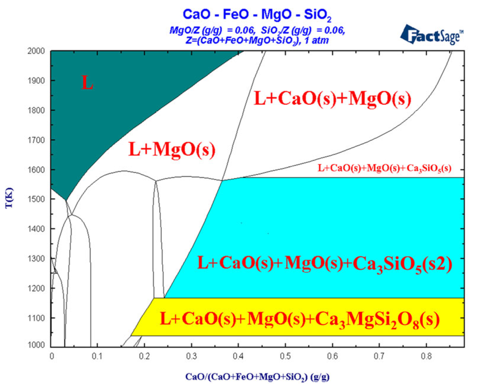
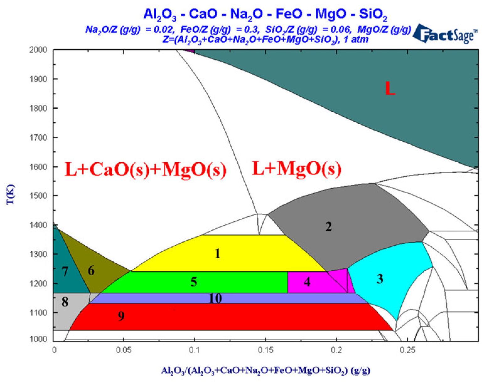
3.3. Liquid-Phase Region Analysis of Slag System
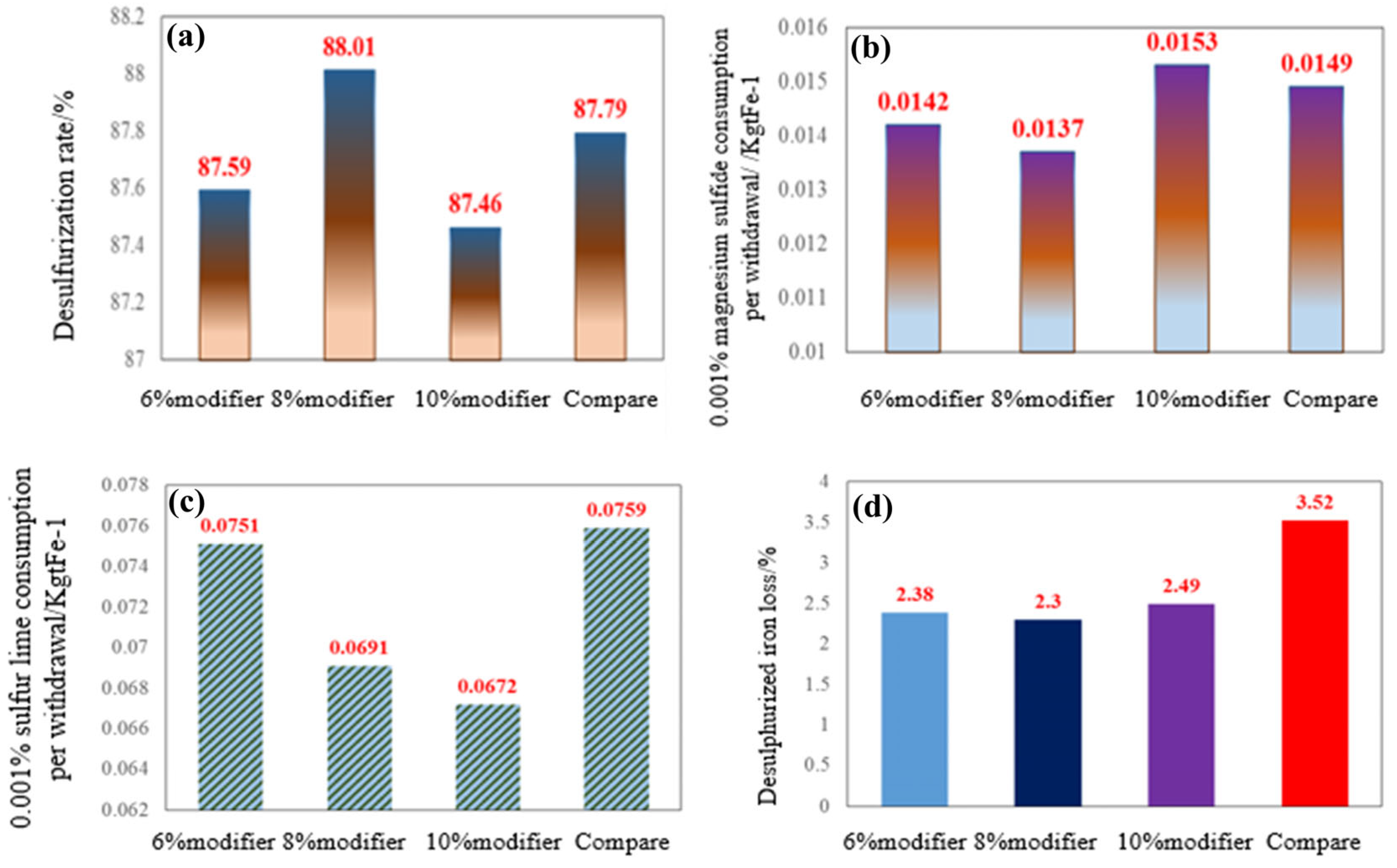
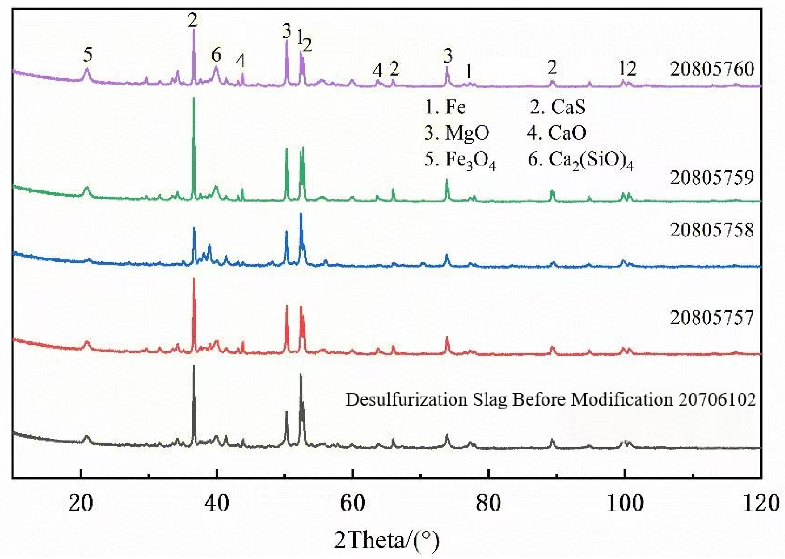
3.4. Analysis of Desulfurization Effect After Slag System Optimization
4. Conclusions
- In response to the issue of high iron loss during the pretreatment desulfurization slagging process in the semi-steel silicon enhancement new technology, a desulfurization modifier containing Na2O and Al2O3 was designed using FactSage thermodynamic calculation software. Industrial tests have verified that adding an 8% modifier to passivated lime can achieve optimal magnesium desulfurization agent consumption and iron loss indicators.
- After modifying the desulfurization slag, the magnesium powder consumption per 0.001% sulfur removal decreased from 0.0149 kg to 0.0136 kg, while the iron loss during slagging reduced from 3.52% to 2.28%. The average slagging time was shortened by 1.5 min, significantly lowering production costs and improving the efficiency of pretreatment desulfurization.
- By modifying desulphurization slag, good industrial verification results were obtained, and the research results have been widely applied in the Pangang production site. However, further improving the reaction efficiency of slag–metal and improving the separation effect of slag and metal will be an important research direction in the future desulfurization process of vanadium and titanium hot metal pretreatment.
- The successful application of desulfurization slag modification technology has laid the foundation for the comprehensive promotion and application of the semi-steel silicon enhancement process, effectively alleviating the long-time historical problem of an insufficient heat sources for semi-steel smelting, and effectively supporting the efficient utilization of vanadium–titanium magnetite in the Panxi area of China.
Author Contributions
Funding
Data Availability Statement
Conflicts of Interest
References
- Qing, J.S.; Li, S.; Xiao, M.F.; Yang, S.X.; Li, J.Q.; Huang, D.H. Research and practice of increase in heavy rail steel endpoint carbon content. Steelmaking 2011, 27, 12–16. [Google Scholar]
- Wang, J.; Lin, D. Effect of converter final controlling on inclusions in the steel. Met. Mater. Metall. Eng. 2012, 40, 20–22. [Google Scholar]
- Yu, G.Q. Study and practice of dephosphorization and carbon conservation technology for high carbon steel. Metall. Collect. 2015, 4, 40–43. [Google Scholar]
- Ji, R.D. Technology of catch carbon to produce medium-high carbon steel in converter. World Iron Steel 2013, 13, 23–26. [Google Scholar]
- He, S.M.; Li, Z.G. Dephosphorization of medium and high carbon steel in reblowing converter. Res. Eng. Technol. 2013, 3, 24–26. [Google Scholar]
- Li, J.X.; Hao, X.D.; Han, X.L.; Liu, L.N.; Qiu, S.T.; Zhao, P. Study of mineralogical morphology on slag in the process of converter. Iron Steel 2009, 44, 41–46. [Google Scholar]
- Wu, Y.P.; Cheng, G.J.; Wang, S.Z.; Liu, H.Q. Control of medium and high carbon steel phosphorus in converter smelting. Res. Iron Steel 2005, 33, 34–36. [Google Scholar]
- Wang, S.M.; He, D.Y. Control of phosphorus in high carbon steel smelting process. J. North China Univ. Sci. Technol. (Nat. Sci. Ed.) 1995, 17, 24–27. [Google Scholar]
- Zhang, H.; Chen, F.Y.; Wang, Y.H. End Point Optimized Control for BOF Steel-Making Process Based on the Characteristic of Subsidiary Material′s Movement. J. Iron Steel Res. 2013, 1, 9–12+46. [Google Scholar]
- Zhao, D.W.; Li, H.B.; Sun, L.; Zhang, Y.; Yan, X.B. Deep dephosphorization of IF steel in converter. J. Iron Steel Res. 2017, 29, 997–1005. [Google Scholar]
- Dai, Y.G.; Wang, L.X.; Song, Y.X.; Lu, L.X.; Li, Y.F. Control of C and Mn elements for conductive pure iron smelting by converter. J. Iron Steel Res. 2016, 28, 6. [Google Scholar]
- Deng, X.Y.; Ma, J.C.; Zhao, W.J.; Cao, B.; Jin, H.J.; Li, S. Process Optimization of High Hot Metal Charging Ratio for EAF Steelmaking. J. Iron Steel Res. 2013, 25, 14–18. [Google Scholar]
- Gu, L.J.; Xu, L.Z.; Liu, N.P. Experimental study on converter blowing semi-steel with coal instead of coke. Iron Steel Vanadium Titan. 1990, 11, 7–10. [Google Scholar]
- Yuan, Z.F.; Wan, T.J.; Li, H. Heat compensation technology for converter steelmaking. Steelmaking 1991, 7, 44–49. [Google Scholar]
- Ke, L.; Wang, S.T. Heat compensation technology for converter with coal. Iron Steel 1995, 30, 4. [Google Scholar]
- Liang, X.L.; Wang, X.H.; He, X.F.; Wang, W.J. Mineral Phase and Utilization of Semisteel Slag Produced During BOF Double Slag Process. J. Iron Steel Res. 2014, 26, 15–20. [Google Scholar]
- Zhang, T. Applied Fundamental Research on Dephosphorization And Vanadium Extraction during Vanadium Extraction by Converter. Ph.D Thesis, Chongqing University, Chongqing, China, 2016. [Google Scholar]
- Ding, M.T. Technological progress of vanadium extraction from vanadium-titanium magnetite. China Nonferrous Metall. 2016, 45, 4. [Google Scholar]
- Meng, L.P.; Zhao, C.; Wang, S.N.; Du, H.; Zheng, S.L.; Zou, X. Improvement of Vanadium Extraction from Extracted Vanadium Residue in China. Iron Steel Vanadium Titan. 2015, 36, 8. [Google Scholar]
- Ma, D. Study on Basic Theory and Process of Vanadium Extraction from Hot Metal with Low Carbon and High Vanadium. Ph.D Thesis, China Iron&Steel Research Institute Group, Beijing, China, 2018. [Google Scholar]
- Li, X.M. The Research on Secondary Vanadium Extraction from Vanadium Residue from PanGang Group Company. Ph.D. Thesis, Wuhan University of Technology, Wuhan, China, 2013. [Google Scholar]
- Chen, P. Practice of KR desulfurization process of iron pretreatment in Xiangsteel Steel Plant. Metall. Mater. 2024, 44, 61–63. [Google Scholar]
- Jiang, W.F.; Tian, L.; Hao, S.; Bo, H.; Ma, T.F.; Zhang, Y. Research on the flow performance regulation of magnesium-based desulfurization slag pretreated molten iron. Steelmaking 2023, 39, 23–29. [Google Scholar]
- Yang, B.; Song, B.; Chen, L.; Sun, H.; Northwood, D.O.; Waters, K.E.; Ma, H. Influence of Top Slag Containing TiO2 and VOx on Hot Metal Pre-Desulfurization. Metals 2024, 14, 910. [Google Scholar] [CrossRef]
- Xu, L.; Qing, G.; Cheng, X.; Xu, M.; Zhao, B.; Liao, J. Experimental Study on Desulfurization and Removal of Alkali Behavior of BF Slag System in Low-Slag Ironmaking. Metals 2023, 13, 414. [Google Scholar] [CrossRef]
- Shen, J.-M.; Lin, C.-M.; Chang, Y.-E.; Lin, H.-J.; Wu, W. Effects of Different CaO/Al2O3 Ratios on the Phase Composition and Desulfurization Ability of CaO-Based Desulfurizers in Hot Metal. Metals 2024, 14, 363. [Google Scholar] [CrossRef]
- Liu, X.; Liu, H.; Wang, Z.; Zang, X.; Ren, J.; Zhao, H. Performance Characterization and Composition Design Using Machine Learning and Optimal Technology for Slag–Desulfurization Gypsum-Based Alkali-Activated Materials. Materials 2024, 17, 3540. [Google Scholar] [CrossRef]
- Echelmeyer, A. Desulfurization agent and powder spraying system of molten iron. In Proceedings of the 7th International Proceedings of Desulphurization Conference, Niagara Falls, ON, Canada, 5–8 May 2002; pp. 1–9. [Google Scholar]
- Li, X.; Wang, H. Research on the desulfurization pretreatment process of pure mafrost water. Nangang Technol. 2003, 4, 4–6. [Google Scholar]
- Ma, C.; Song, M. Research on the pretreatment process of this steel iron and steel. Bensteel Technol. 2001, 7, 2–7. [Google Scholar]
- Shevchenko, A.F. The process of using magnesium particles to replace magnesium-lime for desulfurization of molten iron and equipment improvement. In Proceedings of the 7th International Conference on Desulfurization, New Orleans, LA, USA, 13–17 May 2002; pp. 15–17. [Google Scholar]
- Pan, K.; Guo, L. Development and application of Baosteel iron and iron deep desulfurization technology. Shanghai Met. 2000, 22, 30–36. [Google Scholar]
- Liu, B. Application effects of different molten iron desulfurization processes. Natl. Molten Iron Pretreat. Proc. Tech. Semin. 2003, 11, 17–22. [Google Scholar]


| Carbon Content of Semi-Steel/% | <3.0 | 3.0–3.2 | 3.2–3.4 | 3.4–3.6 | >3.6 |
|---|---|---|---|---|---|
| Ferrosilicon dosage/kg·heat−1 | 300 | 200–300 | 100–200 | 100 | 0 |
| Convert it to an increase in carbon/% | 0.31 | 0.21–0.31 | 0.10–0.21 | 0.10 | 0 |
| Project | S | CaO | FeO | MgO | TotalFe | SiO2 | Desulfurization Rate |
|---|---|---|---|---|---|---|---|
| Silicon-Increasing Process | 4.83 | 32.54 | 12.58 | 9.79 | 41.75 | 5.79 | 96.36 |
| Original Process | 4.46 | 33.67 | 11.71 | 9.16 | 42.60 | 1.20 | 96.52 |
| Mineral Name | Metal Iron | Cao Solid Solution | Cao-Mgo Solid Solution | CaMg(SO4)2 Solid Solution | Iron Oxide | Ferrite | Plaster | Square Magnesium Stone | Calcium Manganese Olivine | CaSO4 Solid Solution | Other |
|---|---|---|---|---|---|---|---|---|---|---|---|
| Wt% | 27.45 | 33.73 | 10.29 | 15.21 | 1.87 | 2.56 | 2.53 | 2.39 | 1.65 | 1.63 | 0.068 |
| Items | CaO | MgO | Al2O3 | FeO | Na2O | SiO2 |
|---|---|---|---|---|---|---|
| Original slag | 39.36 | 11.12 | - | 10.06 | - | 3.06 |
| Original slag + Al2O3 | 36.66 | 10.34 | 4.02 | 9.40 | - | 2.96 |
| Original slag + Na2O | 38.42 | 10.84 | - | 9.85 | 0.96 | 2.96 |
| Original slag + Al2O3 + Na2O | 36.08 | 10.18 | 4.09 | 9.25 | 1.02 | 2.78 |
| F− | Na2O | MgO | Al2O3 | SiO2 | K2O | CaO | TiO2 | Fe2O3 | P2O5 |
|---|---|---|---|---|---|---|---|---|---|
| 2.0 | 1.6 | 2.1 | 79 | 6.9 | 2.0 | 0.8 | 0.3 | 0.6 | 0.1 |
| Items | CaO | Al2O3 | Na2O | F− |
|---|---|---|---|---|
| Requirement | ≥80 | ≥3 | ≥1.0 | ≥0.5 |
| Real control | 80.23 | 3.45 | 1.28 | 0.61 |
| Component | CaO/% | Na2O | S | Calcination | <1 mm Particle Size/% | <0.075 mm Particle Size/% | <0.25 mm Particle Size/% |
|---|---|---|---|---|---|---|---|
| Requirement | ≥85 | ≥1.0 | ≤0.10 | ≤5.0 | 100 | ≥80 | ≥98 |
| Component | CaO/% | Na2O | Al2O3 | Calcination | <1 mm Particle Size/% | <0.075 mm Particle Size/% | <0.25 mm Particle Size/% |
|---|---|---|---|---|---|---|---|
| Requirement | ≥40 | ≥15.0 | ≥40.0 | ≤5.0 | 100 | ≥80 | ≥98 |
| Items | S | CaO | SiO2 | Fe2O3 | FeO | MgO | TotalFe | MetalFe | Al2O3 | Na2O | Sample Size |
|---|---|---|---|---|---|---|---|---|---|---|---|
| Original | 4.77 | 35.07 | 2.07 | 0.75 | 9.64 | 11.37 | 33.63 | 24.79 | 0.60 | - | 20 |
| After optimization | 5.65 | 46.23 | 1.89 | 1.51 | 4.84 | 12.68 | 27.62 | 23.02 | 1.00 | 0.196 | 14 |
| Items | Sulfur Content Before Desulfurizationt/% | Sulfur Content After Desulfurizationt/% | Desulfurization Ratet/% | Slag Removal Time/ min |
|---|---|---|---|---|
| Original | 0.0702 | 0.006 | 91.96 | 8.7 |
| After optimization | 0.0782 | 0.007 | 92.20 | 7.2 |
| Area | Substance Type |
|---|---|
| 1 | L, MgO(s), CaO(s), 3CaO.MgO.2Al2O3(s) |
| 2 | L, MgO(s), 3CaO.MgO.2Al2O3(s) |
| 3 | L, MgO(s), 3CaO.MgO.2Al2O3(s), 3CaO.MgO.2SiO2(s) |
| 4 | L, MgO(s), CaO(s), 3CaO.MgO.2Al2O3(s), 2CaO.SiO2(s) |
| 5 | L, MgO(s), CaO(s), 3CaO.MgO.2Al2O3(s), 2CaO.SiO2(s) |
| 6 | L, MgO(s), CaO(s), 2CaO.SiO2(s) |
| 7 | L1, L2, MgO(s), CaO(s), 2CaO.SiO2(s) |
| 8 | L1, L2, MgO(s), CaO(s), 3CaO.MgO.2Al2O3(s) |
| 9 | L1, L2, MgO(s), CaO(s), 3CaO.MgO.2Al2O3(s), 3CaO.MgO.2SiO2(s) |
| 10 | L, MgO(s), CaO(s), 3CaO.MgO.2Al2O3(s), 3CaO.MgO.2SiO2(s) |
| Spectrum | Number | O | Na | Mg | Al | Si | Ca | Ti | Mn | Fe |
|---|---|---|---|---|---|---|---|---|---|---|
| Mangan-magnesio olivine | 1 | 31.15 | 37.12 | 23.47 | 7.56 | |||||
| Calcium manganese pyroxene | 2 | 31.17 | 0.81 | 2.89 | 12.57 | 18.66 | 18.59 | 3.51 | 10.89 | 0.91 |
| Manganmagnesio olivine | 3 | 21.56 | 38.02 | 23.67 | 0.69 | 6.06 | ||||
| Calcium magnesium pyroxene | 4 | 31.59 | 5.64 | 11.17 | 17.19 | 22.81 | 5.9 | 5.7 | ||
| Calcium magnesium pyroxene | 5 | 31.15 | 5.7 | 11.58 | 17.23 | 22.83 | 4.82 | 6.75 | ||
| Manganmagnesio olivine | 6 | 31.06 | 37.68 | 23.58 | 0.77 | 6.91 | ||||
| Manganmagnesio olivine | 7 | 31.32 | 38.01 | 23.52 | 11.77 | 21.11 | ||||
| Mean | 31.28 | 0.81 | 21.53 | 11.77 | 23.49 | 9.52 | 4.75 | 7.24 | 0.91 | |
| Sigma | 0.21 | 0 | 17.59 | 0.72 | 3.07 | 11.03 | 1.2 | 1.72 |
Disclaimer/Publisher’s Note: The statements, opinions and data contained in all publications are solely those of the individual author(s) and contributor(s) and not of MDPI and/or the editor(s). MDPI and/or the editor(s) disclaim responsibility for any injury to people or property resulting from any ideas, methods, instructions or products referred to in the content. |
© 2025 by the authors. Licensee MDPI, Basel, Switzerland. This article is an open access article distributed under the terms and conditions of the Creative Commons Attribution (CC BY) license (https://creativecommons.org/licenses/by/4.0/).
Share and Cite
Chen, J.; Chen, L.; Wang, L. Modification of Desulfurization Slag for Hot Metal Bearing V-Ti and Industry Application. Metals 2025, 15, 245. https://doi.org/10.3390/met15030245
Chen J, Chen L, Wang L. Modification of Desulfurization Slag for Hot Metal Bearing V-Ti and Industry Application. Metals. 2025; 15(3):245. https://doi.org/10.3390/met15030245
Chicago/Turabian StyleChen, Jun, Lian Chen, and Lijun Wang. 2025. "Modification of Desulfurization Slag for Hot Metal Bearing V-Ti and Industry Application" Metals 15, no. 3: 245. https://doi.org/10.3390/met15030245
APA StyleChen, J., Chen, L., & Wang, L. (2025). Modification of Desulfurization Slag for Hot Metal Bearing V-Ti and Industry Application. Metals, 15(3), 245. https://doi.org/10.3390/met15030245