Article

Enhanced Cutting Performance of 50Cr15MoV Martensitic Stainless Steel Through Controlled Residual Austenite Stability

1
School of Materials Science and Engineering, Guangdong Ocean University, Yangjiang 529500, China
2
Yangjiang Advanced Alloys Laboratory, Guangdong Ocean University, Yangjiang 529500, China
3
School of Materials and Energy, Guangdong University of Technology, Guangzhou 510000, China
4
State Key Laboratory for Advanced Metals and Materials, University of Science and Technology Beijing, Beijing 100083, China
*
Authors to whom correspondence should be addressed.
Metals 2025, 15(1), 95; https://doi.org/10.3390/met15010095
Submission received: 5 December 2024 / Revised: 4 January 2025 / Accepted: 16 January 2025 / Published: 19 January 2025
(This article belongs to the Special Issue Recent Insights into Mechanical Properties of Metallic Alloys)

Abstract

:
The relationship between the stability of tool materials and their cutting performance is a critical technical challenge for the manufacturing industry, which is essential for selecting appropriate treatment processes to achieve superior treatment tool performance. In this paper, a standard cutting tool experiment was used to study the sharpness of the knife with different residual austenite content. The cutting edges of the knife were characterized by an optical microscope (OM), scanning electron microscope (SEM), electron back scattering diffraction (EBSD), and transmission electron microscope (TEM), to analyze the relationship between tool edge hardness and microstructure. The microstructure stability of the material was analyzed by a separated Hopkinson pressure bar (SHPB) experiment. The results show that the hardness and cutting performance of the knives are affected by the joint action of carbide and residual austenite, with an initial increase followed by decreases as the heat treatment quenching temperature increases. After the knife material is treated by cryogenic process, the hardness of the knife is increased by 3.89 HRC, the initial sharpness by 15.3%, and the sharpness and durability by 18.8%. The residual austenite in the knives was found to be unstable and easy to transformation during high-rate deformation processes. This study elucidates the effect of residual austenite content on the sharpness of the knives, providing a foundation for the reasonable control of residual austenite content in the actual production settings.

1. Introduction

Since ancient times, from bronze knives, iron knives, to the present stainless-steel knives, knives have never been absent from human civilization, playing a vital role in the human kitchen. In today’s kitchens, the function of the knives is more and more refined and people’s understanding of the knives and its cutting process is also more profound; however, the sharpness of the knife remains the most important factor when selecting a tool [1,2]; A sharper tool means achieving more with less effort [3]. At present, in a large number of studies [4,5,6,7,8,9,10,11,12], it can be determined that the sharpness of the knife is mainly determined by the shape of the cutting edge and the material. During the cutting process of the knife, the stress concentration at the tip of the cutting edge drives the knife to cut the material more easily. At the same time, the intense friction between the cutting edge and the cutting material causes wear, leading to a decline in the knife’s sharpness after each use. McCarthy [13] developed a finite element model to analyze how factors such as the width of the edge tip, the angle of the edge, and the shape and size of the knife affect the sharpness performance. The study found that all tool shape variables would affect the sharpness performance, with the edge tip width having the most significant effect. The stress of the cutting edge is related to the shape and size of the cutting edge, and the hardness, toughness, and wear resistance of the cutting tool material determine the wear of the cutting edge in the cutting medium. Zhang [14] quantitatively analyzed the relationship between cutting depth and cutting edge wear through mathematical modeling, considering the effects of material wear resistance, the cutting edge angle, and cutting edge tip width on the knife’s cutting performance. The study found that the wear mechanism changes after the contact stress between the knife’s and the cutting medium decreases.
Residual austenite is the untransformed austenite during the martensitic phase transition of materials, which plays an important role in the properties of materials. In the cutting process, the content, form, and distribution of residual austenite will affect its stability, and then affect the cutting performance of the material [2]. The stability of residual austenite is influenced by various factors such as material chemical composition, process treatment, and stress state [15,16,17]. Zhu [18] obtained 23CrNi3MoA steel with different contents of residual austenite through carburizing, analyzing the influence of residual austenite volume fraction, size, and distribution on the microstructure’s mechanical stability and the evolution rule of the material during the friction and wear process. The study determined the reverse change mechanism of residual austenite during the friction and wear process. The carbon content of 50Cr15MoV martensitic stainless steel is about 0.5%, the chromium content is about 15%, and a small amount of molybdenum, vanadium, and other alloying elements are added. Compared with Cr13 martensitic stainless steel, the carbon and chromium content have been increased, resulting in higher hardness [19,20]. The hardness can reach 58HRC after quenching, ensuring the sharp performance of the tool, and it is often used in high-grade knives, scissors, and medical equipment. Many scholars [19,20,21,22,23,24,25] have studied the effect of quenching temperature on the microstructure and properties of 50Cr15MoV martensitic stainless steel and found that the content of residual austenite increases with the increase in quenching temperature, and its properties are jointly influenced by residual austenite and carbide.
In summary, most of the research focuses on improving the cutting performance of the knife by changing the geometry of the knife or improving the performance of the tool steel through the microstructure of the material regulation. The relationship between the cutting performance of the knife and the stability of the microstructure, and the relationship between the performance of the steel and the sharpness of the knife, are often overlooked. The development of this work is more conducive to a clear understanding of the sharp performance of the tool.
In this paper, 50Cr15MoV martensitic stainless steel was treated by different processes including different quenching temperatures, tempering, and cryogenic treatment, to obtain sample cutters with different residual austenite content. The performance of 50Cr15MoV martensitic stainless-steel cutters with different residual austenite content was compared, and the stability of residual austenite in the material was analyzed.

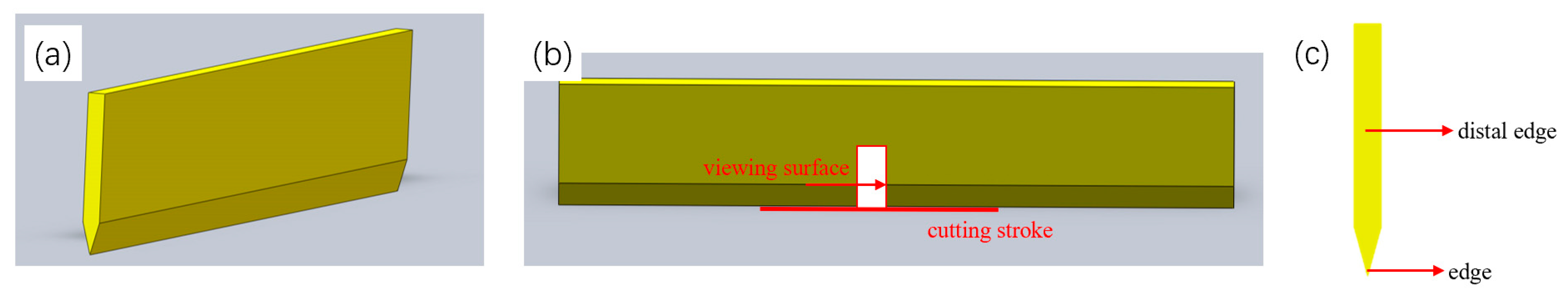
2. Materials and Methods

In this experiment, a 50Cr15MoV steel plate purchased in the market with a thickness of 3 mm. The chemical composition of the steel plate was measured by a SpecEYECCD4000 direct reading spectrometer from Suzhou Mega Instruments Co., Ltd., Suzhou, China, and the chemical composition is shown in Table 1. A 100 mm × 20 mm sample was cut from the steel plate by wire cutting, and the sample was put into the Muffle furnace and held at different quenching temperatures for 20 min for oil quenching, and then immediately tempered at 180 °C for 3 h. After quenching at 1080 °C, the sample was held at −196 °C for 1 h for cryogenization, and then immediately tempered at 180 °C for 3 h. The different process treatments of the samples are shown in Table 2. Subsequently, the sample was polished to remove the surface oxidation layer and decarburization layer, and then the sample was processed on the grinder, and the cutting edge was cut at an angle of 19°. The test knife sample is shown in Figure 1.
The sharpness performance is tested in accordance with ISO8442-5:2004 (E) [26] on the type LX01 blade sharpness persistence tester. Under the premise of a fixed tool, a mechanical device is used to deliver the cutting medium. The cutting medium is a standard test sandpaper with a silicon dioxide content of 5%, under the normal load p = 50N, the stacked sandpaper is clamped with a force of 130N, and the tool completes a cutting once back and forth, which is called a cutting cycle, and each cycle includes two strokes forward and backward. Each cycle is two strokes forward and backward. The stroke length is 40 mm and the moving speed is 50 mm/s. According to ISO8442-5:2004 (E) [26], the cutting depth of the first three cutting cycles is the initial cutting thickness, which is used to characterize the initial sharpness (ICP) of the knife. The total cutting thickness after the completion of all 60 cycles is called the cumulative cutting thickness, which is used to characterize the sharp durability of the tool (TCC). The sharpness of the knife was characterized by ICP and TCC.
The sample was cut at the cutting point of the knife that completed the sharpness performance test, and the observation surface was the edge and far edge of the tool section, as shown in Figure 1. Metallographic observation and scanning observation were carried out on the observation surface, and an EBSD test was carried out on the edge and far edge. After grinding the sample on SiC metallographic sandpaper to 2000 mesh sandpaper, the semi-automatic polishing machine carried out mechanical polishing; the polishing liquid was 0.25 μm diamond polishing liquid. Then, the ground and polished sample was washed with alcohol, and dried with a hair dryer, and the microstructure was observed. The prepared sample was eroded with 4% nitrate alcohol solution, and the metallographic structure of the sample was observed with a DMI8C Leica optical microscope, followed by a TESCAN CLARA scanning electron microscope. The sample was electrolytically polished; the electrolytic polishing liquid was 50 mL perchloric acid and 450 mL anhydrous ethanol, the polishing working voltage was 20 V, and the polishing time was 10 S. Then, the EBSD test was carried out using the field emission scanning electron microscope with an EBSD probe to analyze the phase content of the microstructure, and the EBSD data were analyzed and processed using Channel5 software.
After the test knife was cleaned, a Rockwell hardness test was carried out with an HRS-150 Rockwell hardness tester on the back of the knife; the total test force is 1471 N, and the allowable error is ±1%. Five points were tested for each knife, and the distance between the adjacent indentation center and the indentation center to the knife edge was greater than 3 mm. A Vickers hardness test was carried out on the edge and far edge of the knife section, the polished sample was cleaned by ultrasonic wave, and the microhardness test was carried out on the TIME6614AT Vickers hardness tester from Beijing Times peak Technology Co., LTD, Beijing, China, after drying. The loading force was 0.5 N, and the load retention time was 15 S. Five points were taken from the center and edge of all the samples, and the distance between the test points was 5 mm. The average hardness of 5 test points of the core and the edge is taken as the test result, and the hardness of the core and the edge are compared.

3. Results and Analyses
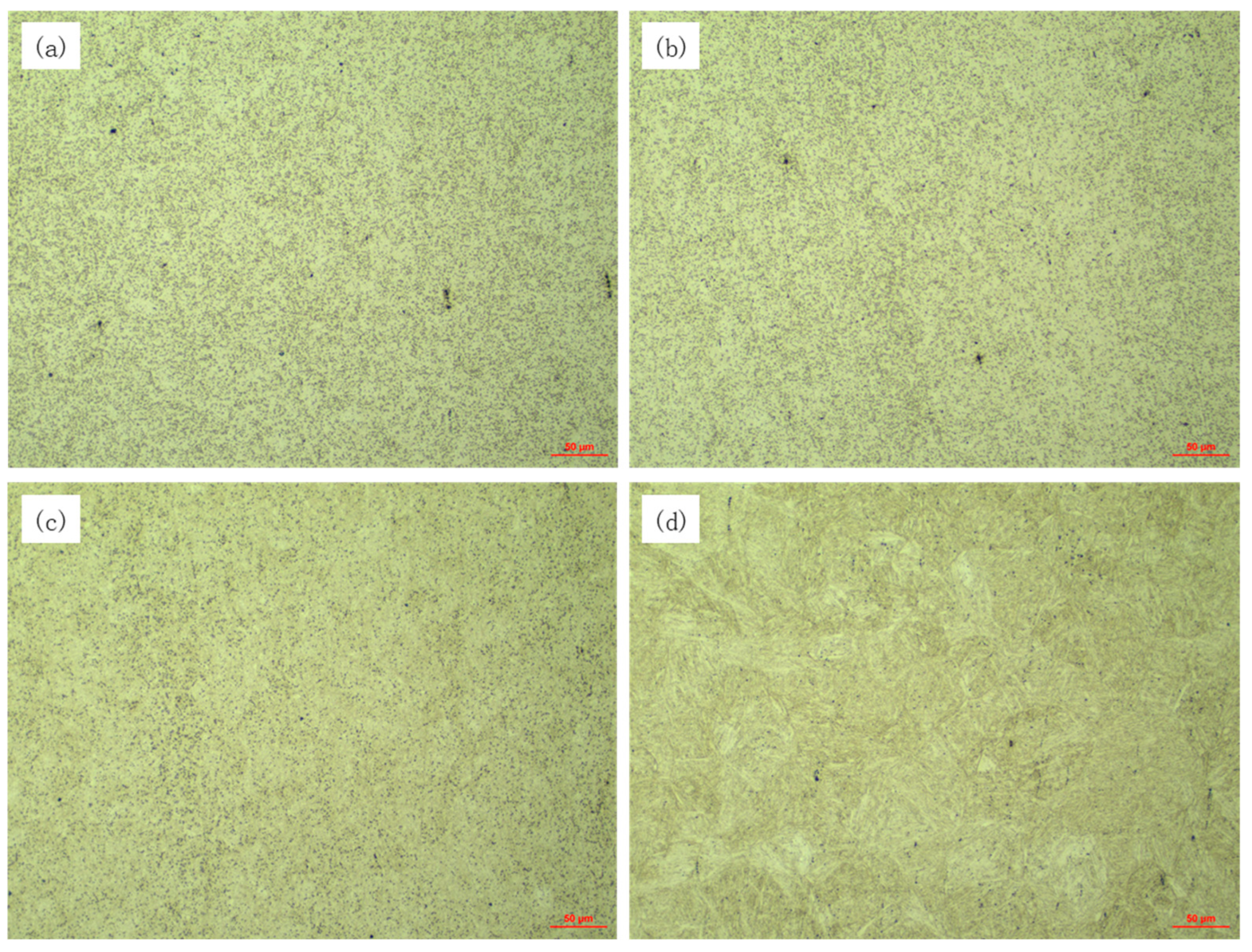
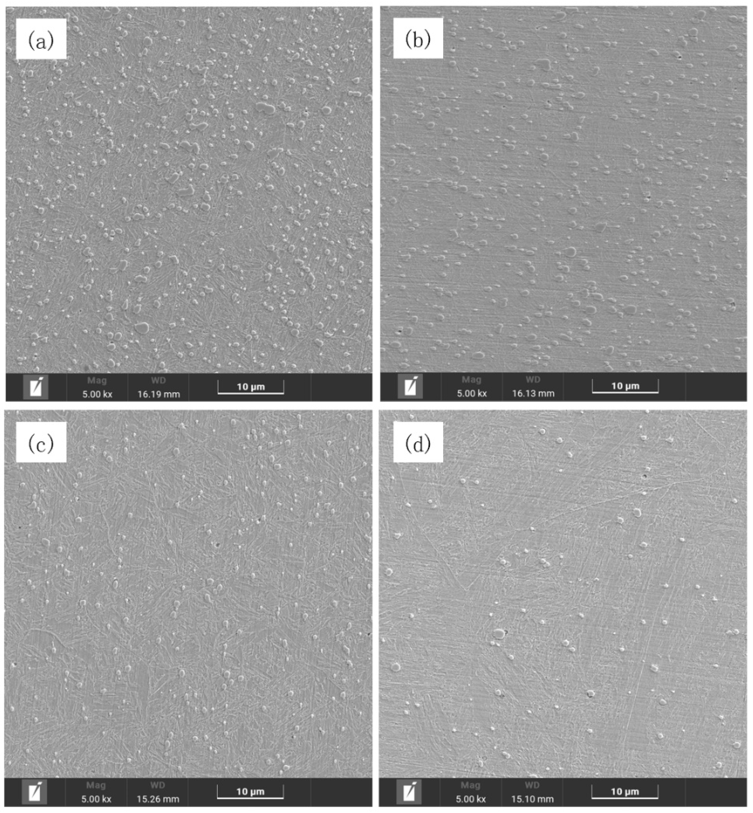
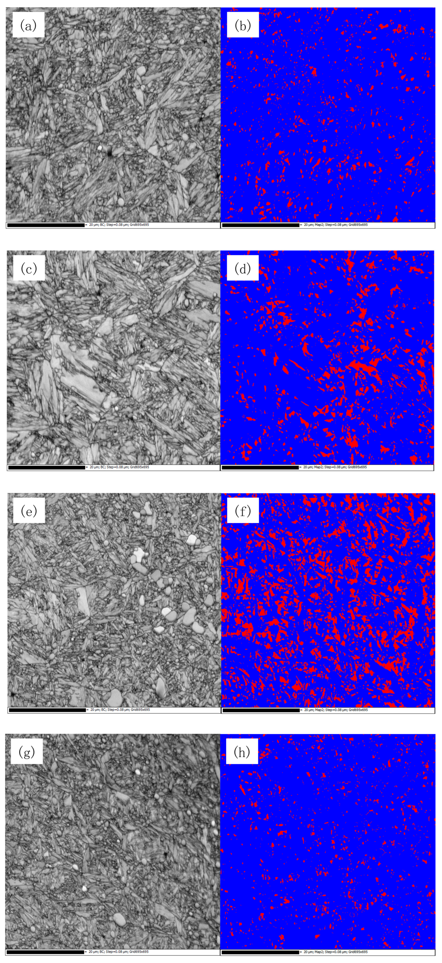
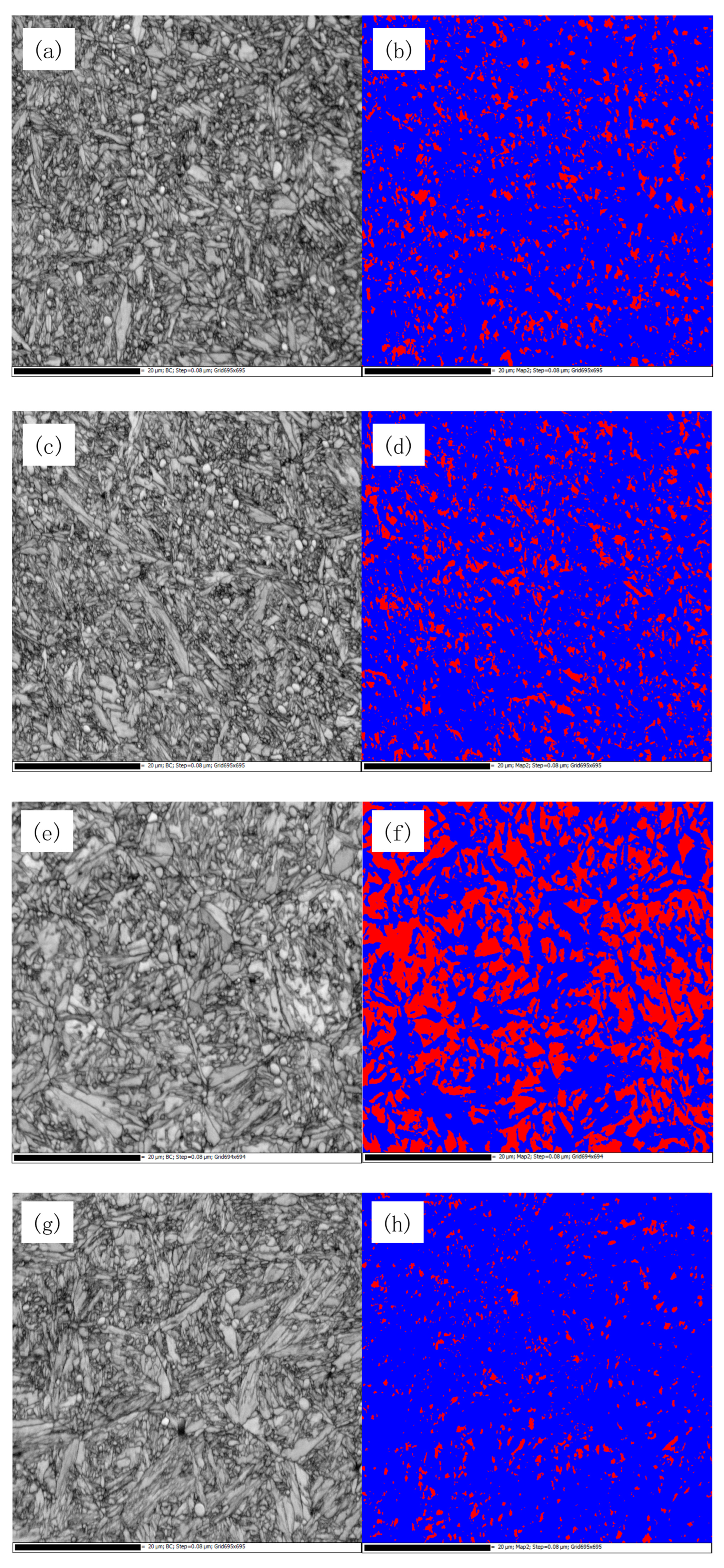
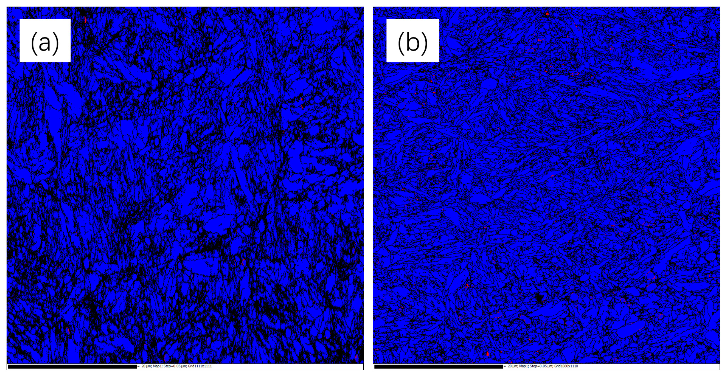
3.1. Microstructure

The microstructure of the sample after different processes is shown in Figure 2 and Figure 3. Figure 2a–c and Figure 3a–c show the optical and scanning microstructure at different quenching temperatures. The particles distributed on the surface of the figure are carbides, which are mainly distributed on the prior austenite grain boundaries and within the martensite of the prior austenite grains. According to the distribution of carbides in Figure 3, it can be observed that as the quenching temperature increases from 1020 °C to 1080 °C, carbides gradually dissolve back into the matrix, and the carbides on the surface of the sample reduce from 9.21% to 3.31%. During the quenching process at 1020 °C, there is still a large number of carbides on the surface topography; the content was 9.21%. When the quenching temperature reached 1080 °C the content was 6.93%, and when the quenching temperature reached 1080 °C, the carbides on the surface topography were sparsely distributed and the content was 3.31%. Carbide has excellent wear resistance due to its extreme hardness, and the wear resistance of the material plays an important role in improving the cutting performance of the tool.
However, the undissolved carbide will reduce the carbon content of the material matrix, thereby reducing the hardness of the material, and the wear resistance of the material will also be reduced. Therefore, there is a suitable value for the carbide content on the surface of the material to achieve optimal performance. Figure 2d and Figure 3d are the microstructure of the samples treated by the cryogenic process, and it can be seen that the surface carbide is further reduced to 1.76%.
Figure 4 and Figure 5 show the distribution of residual austenite in the EBSD test at the edge and far edge of knife samples of different processes, in which red is the residual austenite phase and blue is the martensitic phase. The comparison of residual austenite content is shown in Figure 6. It can be found from the figure that the residual austenite content of the whole material gradually increases with the increase in quenching temperature. In the 1020 °C quenching process, the volume fraction of residual austenite is 6.44%. In the 1050 °C quenching process, the volume fraction of residual austenite is 10.97%. During the quenching process at 1080 °C, the volume fraction of residual austenite increased to 21.86%, while the volume fraction of residual austenite decreased to 4.43% after cryogenic treatment. The main reason for the change in residual austenite content is that as the quenching temperature increases from 1020 °C to 1080 °C, the amount of dissolved carbides in the material matrix increases, while carbon elements and alloying elements can improve the stability of the austenite phase in the matrix and then reduce the martensite transition temperature, finally leading to more austenite remaining untransformed after the quenching process [27,28]. In Figure 4, the grain boundaries of the primitive austenite can be identified by the orientation of martensite. Compared with Figure 4a, the martensitic lath size in 4b and 4c is thicker, and white massive residual austenite without martensitic phase transition appears because the grain size of the primitive austenite is larger and more stable under high-temperature conditions, so obvious residual austenite can be observed after quenching at 1080 °C. At the same quenching temperature, compared with the material without cryogenic processing, the content of residual austenite is significantly reduced, because as the temperature continues to decrease, the martensitic transition endpoint temperature will also decrease. In the cryogenic treatment, the residual austenite will continue to transform to martensite. At the same time, the residual austenite content of the cutting edge is higher than that of the far edge, the martensite changes, and the residual austenite content increases due to excessive external stress in the sharpening process of the cutting edge. For the knife treated by a cryogenic process, the residual austenite content at two locations has almost no change, the tissue of the sample treated by cryogenic treatment is more stable, and the tissue subjected to greater external stress will not change. The presence of the right amount of residual austenite has a positive effect on the microstructure of the material, which can improve ductility and wear resistance. A previous study [18] has revealed the relationship between the phase transition of residual austenite and the wear mechanism during the friction process, and a certain amount of residual austenite can reduce the stress concentration caused by the transition from austenite to martensite and can improve wear resistance and ductility.
Combined with the distribution of carbides and the content of residual austenite treated by different processes, the change in carbides and residual austenite content is related. With the increase of quenching temperature, the dissolution amount of carbides increases, the content of C and alloying elements in the matrix increases, the austenite in the matrix becomes more stable, and the residual austenite content also increases.
The TEM structure of the two groups of samples is shown in Figure 7, where Figure 7a is the structure of the sample of process 3, Figure 7b is the structure of process 4, and Figure 7c is the high-resolution map of the marked area in Figure 7b. The crystallographic data were calculated by the diffraction spots of the matrix and compared with the crystal face spacing database of the phase, confirming that the sample matrix was martensitic and exhibited a lath-like structure, and the martensite laths in Figure 7b are smaller and more closely packed, arranged in parallel. The interface between the adjacent martensite lath phase is not obvious, and there are layer fault substructures in fine martensite. After treatment with liquid nitrogen, the sample’s dislocation density significantly increased, leading to strong dislocation hardening, which provides additional work hardening capability in the early deformation stage of the sample and enhances the strength of the material [29,30,31].

3.2. Knife Performance Comparison

Martensitic stainless steel can improve the mechanical properties of the material by adjusting the process; quenching temperature is an important parameter to determine the hardness of the material, cryogenic treatment can promote the transformation of residual austenite to martensite, and the increase in martensite content can improve the hardness of the material. Figure 8 shows the change in hardness of the test tool after different processing processes. With the change in quenching temperature, the hardness first increases and then decreases and reaches the maximum value at 1050 °C; the hardness value is 56.33 HRC. Under the condition of 1080 °C quenching temperature, the hardness of the samples after cryogenic treatment is increased by 3.89 HRC. The hardness of martensitic stainless steel after different processes is mainly affected by the content of carbide and residual austenite. Under the condition of a lower quenching temperature of 1020 °C, the amount of dissolved carbide is less, the content of carbon in the matrix is reduced, and the hardness is not high. With the increase in quenching temperature, carbide continuously dissolves into the austenitic matrix, which can improve the supersaturation and lattice distortion of carbon elements in the martensitic matrix formed by quenching treatment; the hardness of the material also increases and the hardness reaches the maximum value 56.33 HRC at 1050 °C quenching process. With the further increase in quenching temperature to 1080 °C, the carbon element in the matrix continues to increase, and the stability of austenite improves. More austenite cannot be transformed into martensite during quenching treatment, so the content of residual austenite also increases; at this time the effect of residual austenite content on the hardness is greater than that of carbide, and the hardness of the material is reduced to 54.97 HRC. After the quenching temperature conditions increase the cryogenic process, the residual austenite content decreases from 21.84% to 4.43%, and its influence on the hardness is also greatly reduced, so the hardness of the material is increased by 3.89 HRC.
After different process adjustments, the structure of the test knife is changed greatly, and these changes inevitably lead to alterations in the material properties. The sharpness performance of the tool treated by different processes is shown in Figure 9. It can be observed from the figure that the initial sharpness and sharpness durability of the tool that underwent process 2 reached a maximum value, and the sharpness of the knife that underwent process 4 is 18.8% higher than that of the knife of process 3. The sharpness of the knife after cryogenic treatment does not reach the knife of process 2 at a quenching temperature of 1050 °C. Although cryogenic treatment greatly reduces the residual austenite content, under the condition of 1080 °C quenching, the carbide in the material dissolves into the matrix, significantly reducing the carbide content on the surface. Carbides have high wear resistance and play an important role in improving the sharpness of the knife. However, even though the residual austenite content of process 4 is very low, its sharpness is not greatly improved due to the reduction in carbides on the surface.
As shown in Figure 10, the hardness of the far edge of the knife without cryogenic processing is higher than that of the edge, while the hardness of the far edge and the edge of the tool with cryogenic treatment is almost the same. With the increase in quenching temperature from 1020 °C to 1080 °C, the hardness of the knife edge and the far edge increased first and then decreased, and the hardness of the samples after cryogenic treatment was much higher than that of the samples without cryogenic processing.

3.3. Microstructure Stability Analysis

The sample of Φ 3 × 2.4 mm was cut from the knife material of processes 3 and 4, and the Hopkinson pressure rod (HPB) test was carried out. The strain rate was 5000 s−1, and the real stress-strain curve obtained is shown in Figure 11. In the initial stage of the sample, an obvious elastic stage and yield stage can be seen, but there is no obvious strengthening stage. In the initial stage of strain, the stress of the material presents a linear increase trend with the increase in strain, which is the stage of elastic deformation. After the end of the elastic deformation stage, the material begins to enter the elastoplastic deformation stage, the stress growth of the material becomes slow, there is an obvious yield platform, and the upper and lower yield points appear on the yield platform. At the high strain rate of 5000 s−1, stress changes due to the transfer of stress waves, and the distribution of stress is uneven, which manifests as stress fluctuations on the yield platform, so the upper and lower yield points appear, and the stress also shows similar fluctuations in the subsequent strain [32]. Then, the stress of the material does not continue to rise with the increase in strain, and there is no strain-strengthening phenomenon. By comparing the mechanical curves of two different process materials, it can be found that the material with cryogenic treatment has a slightly higher yield strength and smaller strain.
The comparison of the structure of the sample before and after the Hopkinson pressure rod test is shown in Figure 12. After the pressure rod test, the carbide on the surface of the material in contrast to Figure 3c,d.Under the strain rate condition of this experiment, the SHPB test is in an adiabatic environment, and the deformation at a high strain rate is accompanied by a temperature rise. The mechanical energy generated during the plastic deformation is converted into heat. The material undergoes an adiabatic heating process [32,33,34,35], which leads to the precipitation and growth of carbides in the material. The phase distribution diagram after the SHPB experiment is shown in Figure 13. There is almost no residual austenite phase in the samples treated by the two processes, and the residual austenite is unstable in the process of plastic deformation at a high rate.

4. Conclusions

(1)
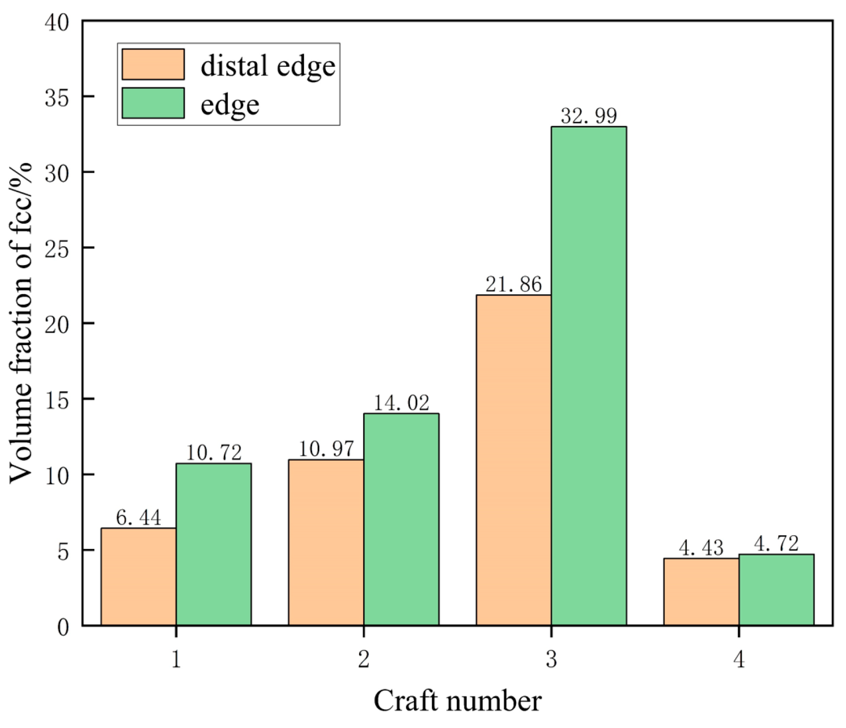
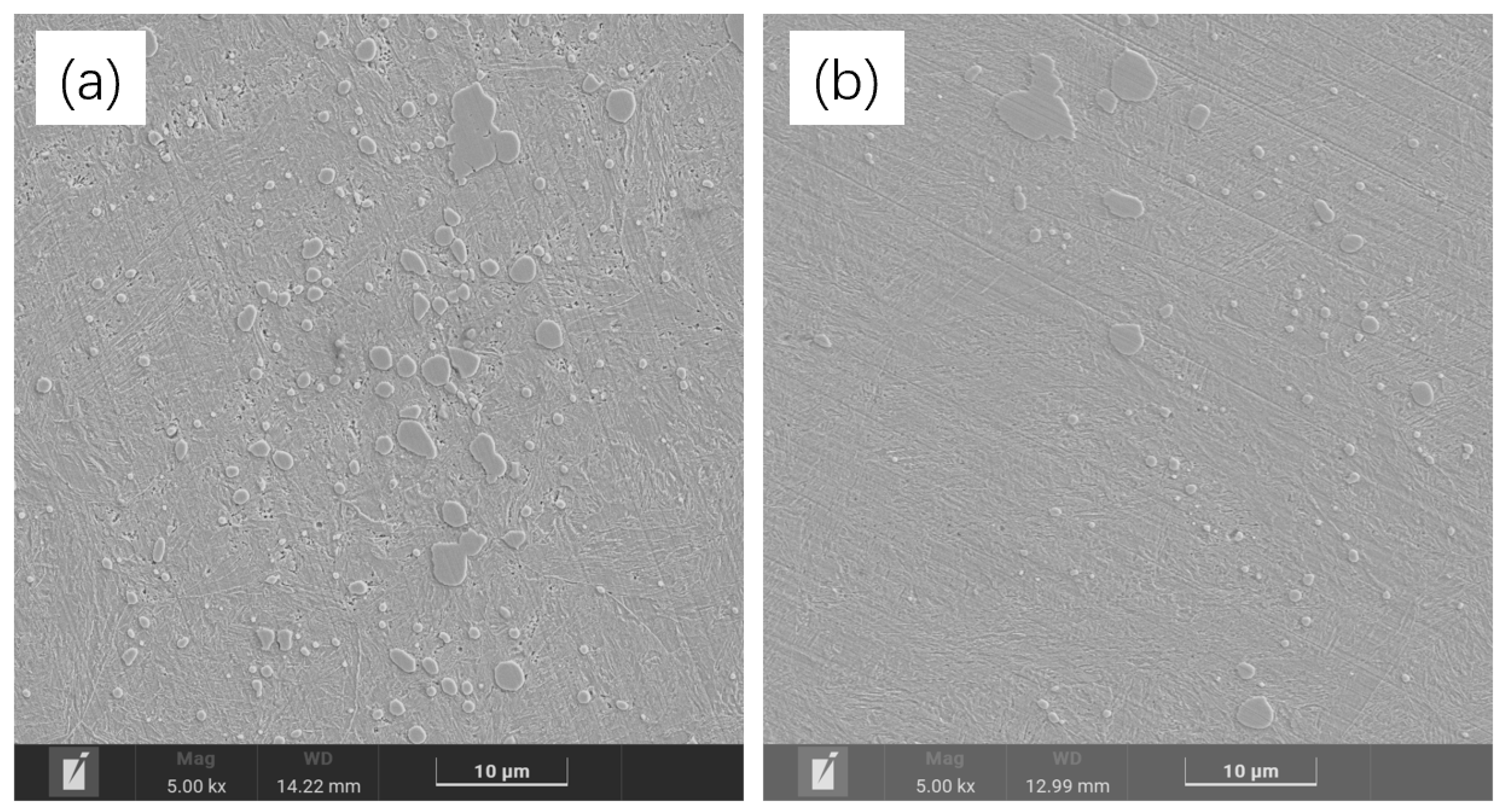
The microstructure of 50Cr15MoV after different processes including different quenching temperatures, tempering, and cryogenic treatment is composed of plate martensite, undissolved carbide, and residual austenite. When the quenching temperature increased from 1020 °C to 1080 °C, the content of undissolved carbide decreased from 9.21% to 3.31%, and the volume fraction of residual austenite increased from 4.43% to 21.84%. Under the same quenching and tempering conditions, the addition of the cryogenic process reduced the residual austenite in steel by 17.43%, and the martensitic lath became smaller, and a large number of fault substructures appeared.
(2)
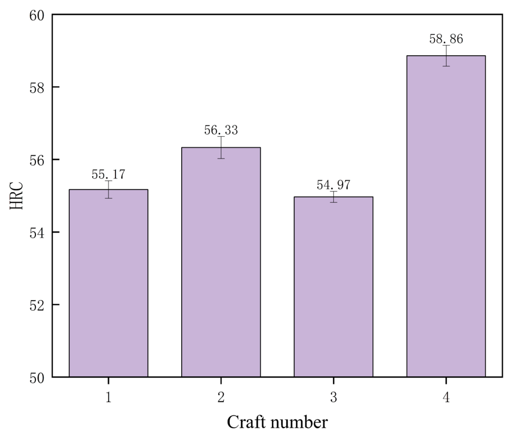
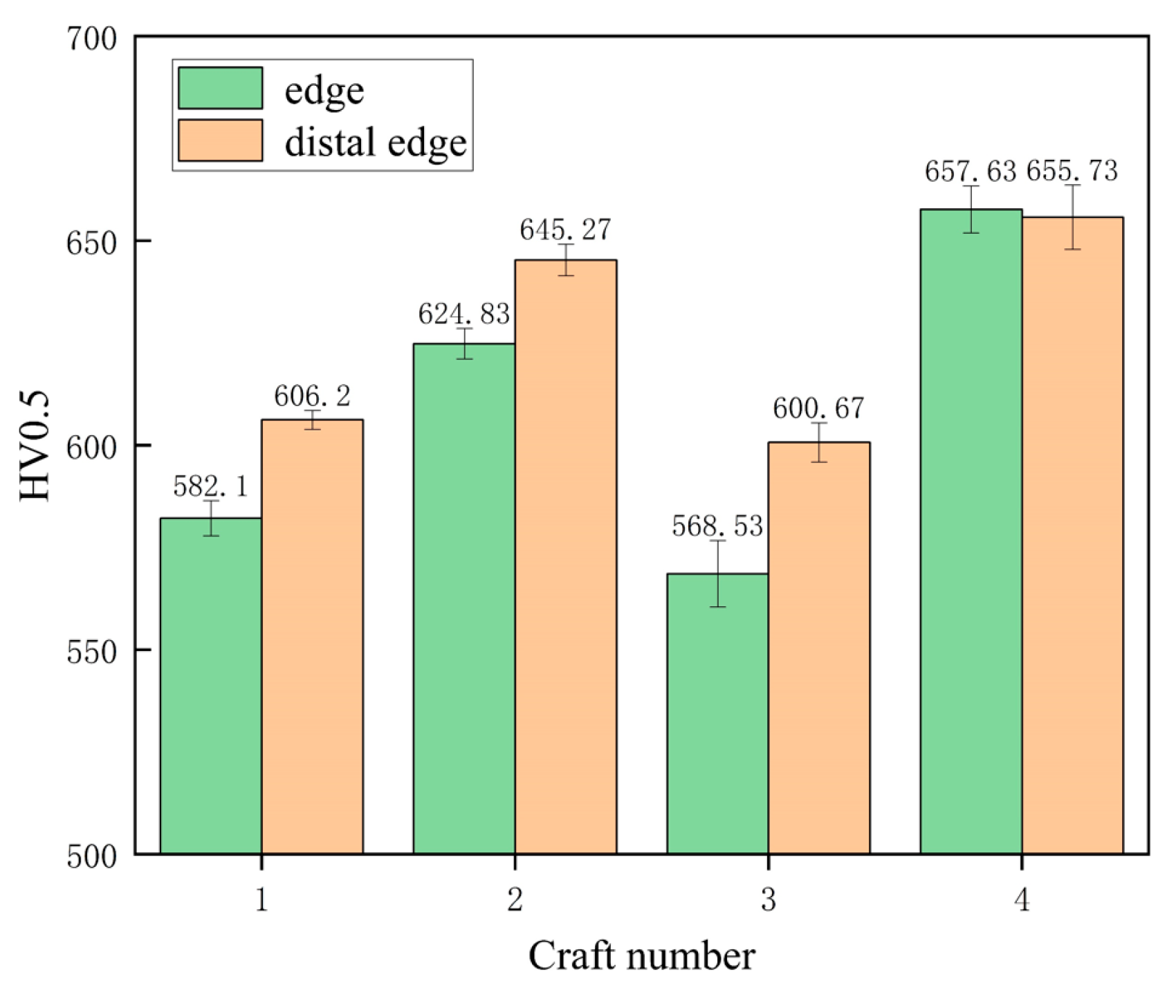
As the quenching temperature increased from 1020 °C to 1080 °C, the hardness of 50Cr15MoV increased from 55.17 HRC to 56.33 HRC and then decreased to 54.97 HRC, reaching the maximum value of 56.33 HRC when the quenching temperature was 1050 °C. The hardness of the material increased by 3.89 HRC after cryogenic treatment.
(3)
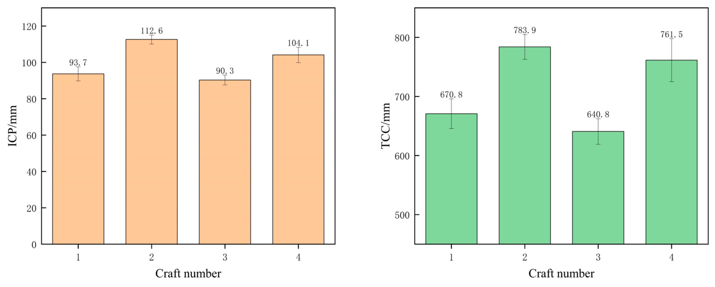
When the quenching temperature increased from 1020 °C to 1080 °C, the sharpness performance of 50Cr15MoV first increased and then reduced; when the quenching temperature is 1050 °C, the sharp performance of the knife is the best, the ICP was 112.6 mm and TCC was 783.9 mm. The ICP of the knife after cryogenic treatment increased by 15.3% and TCC increased by 18.8%.
(4)
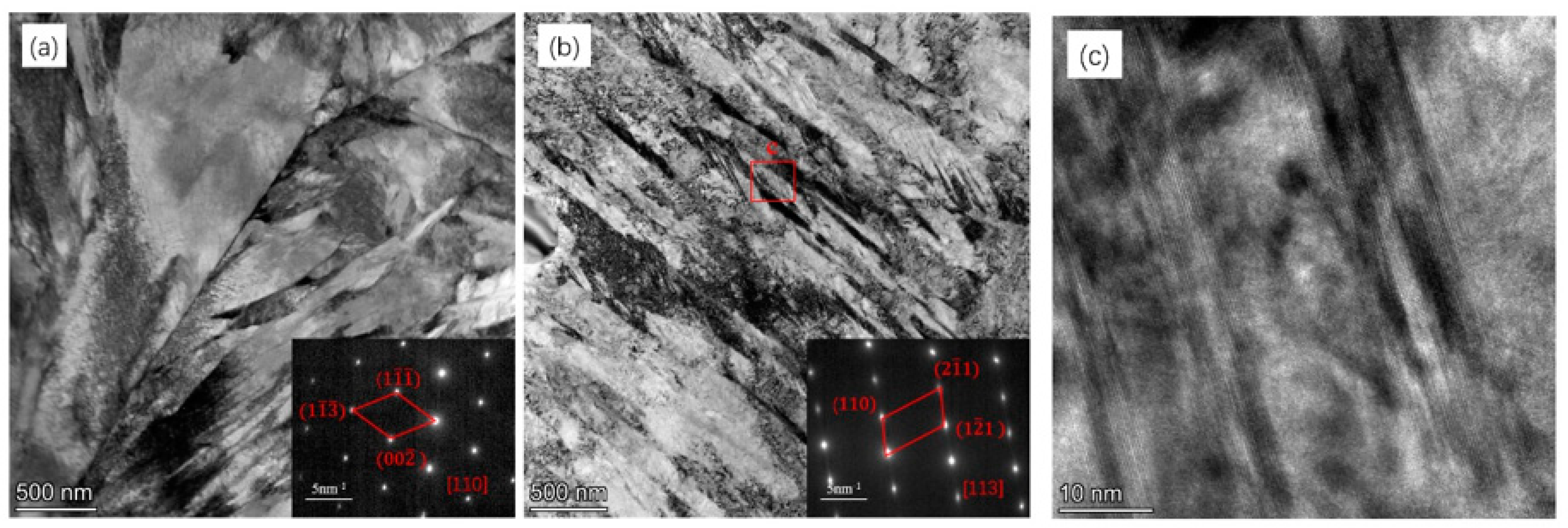
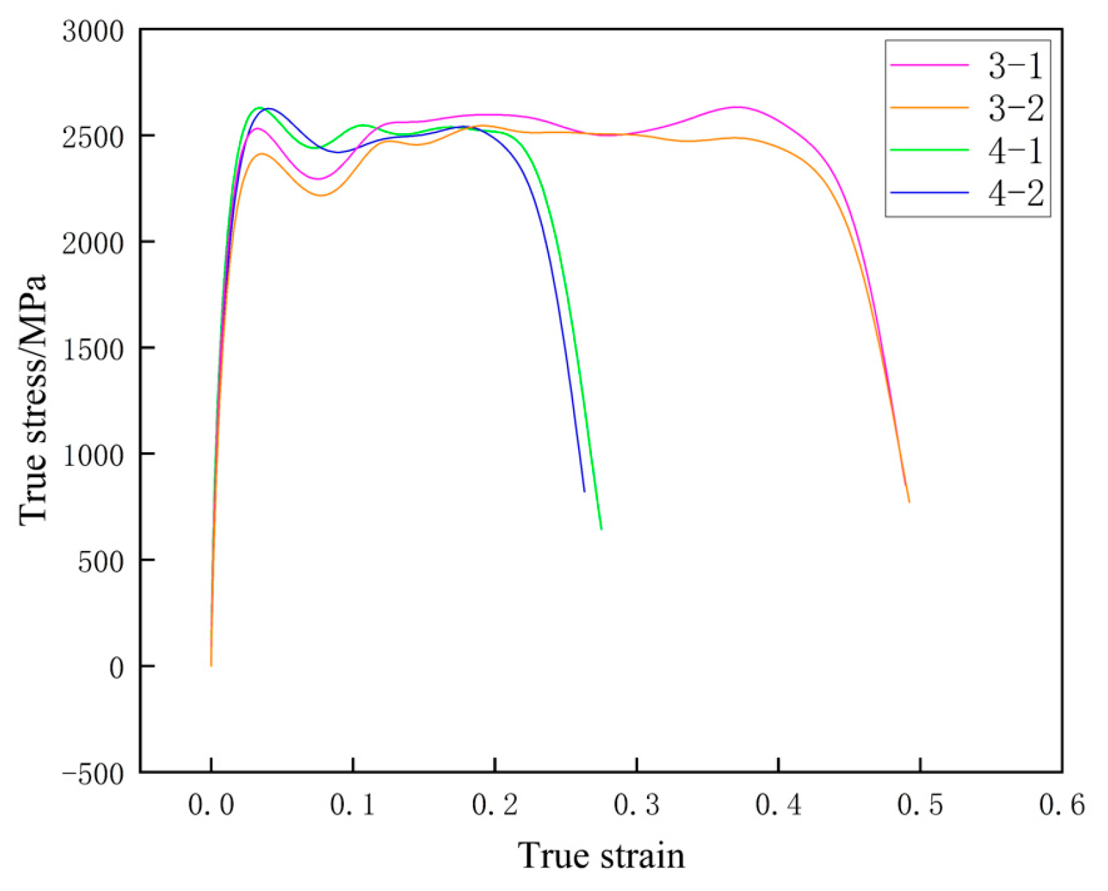
After processing, a large number of lamination-fault substructures are formed, which can improve the strength of the material and reduce the strain. The residual austenite in the material was unstable, and no residual austenite was found at the high deformation rate of 5000 s−1.

Author Contributions

Conceptualization, F.G. and P.Z.; methodology, W.L.; validation, Z.P., G.L. (Guangyi Lu), and G.L. (Guoqing Li); formal analysis, Z.P.; investigation, G.L. (Guoqing Li); resources, G.L. (Guangyi Lu); data curation, Z.P.; writing—original draft, F.G.; writing—review and editing, P.Z. and C.S.; visualization, W.L.; supervision, C.S.; project administration, F.G.; funding acquisition, W.L. All authors have read and agreed to the published version of the manuscript.

Funding

This research was funded by the Key Industry Talent Revitalization Project of Alloy Materials and Hardware Knife and Scissors in Yangjiang, grant number RCZX2023012 and Scientific Research Start-up Project of Guangdong Ocean University 360302032201.

Data Availability Statement

The original contributions presented in the study are included in the article, further inquiries can be directed to the corresponding authors.

Conflicts of Interest

The authors declare no conflicts of interest.

References

  1. Gregory, G.; Hamby, R. Sharp edge cutting technology—A review of hand held and machine knives/blades and their sharp edge retention. Surf. Eng. 2000, 16, 373–378. [Google Scholar] [CrossRef]
  2. Wu, D.; Qu, S.; Zhang, Q.; Zhou, H. Enhanced wear resistance of blades made of martensitic steels: A study of diverse α′-matrix/carbide microstructures. Mater. Charact. 2023, 201, 112939. [Google Scholar] [CrossRef]
  3. Claudon, L.; Marsot, J. Effect of knife sharpness on upper limb biomechanical stresses—A laboratory study. Int. J. Ind. Ergon. 2006, 36, 239–246. [Google Scholar] [CrossRef]
  4. Bush, R.; Gill, J.; Teakell, J. Heat Treatment Optimization and Fabrication of a 440C Stainless Steel Knife. J. Miner. Met. Mater. Soc. 2016, 68, 3167–3173. [Google Scholar] [CrossRef]
  5. Verhoeven, J.D.; Pendray, A.H.; Clark, H.F. Wear tests of steel knife blades. Wear 2008, 265, 1093–1099. [Google Scholar] [CrossRef]
  6. Kurt, A.; Kose, E.; Sahinbaskan, T. The Effects of Blade Angle on Blade Stresses During Cutting of Different Kinds of Paper Materials. J. Mech. Eng. 2009, 55, 633–640. [Google Scholar]
  7. McCarthy, C.T.; Hussey, M.; Gilchrist, M.D. On the sharpness of straight edge blades in cutting soft solids: Part I–indentation experiments. Eng. Fract. Mech. 2007, 74, 2205–2224. [Google Scholar] [CrossRef]
  8. Roscioli, G.; Taheri-Mousavi, S.M.; Tasan, C.C. How hair deforms steel. Science 2020, 369, 689–694. [Google Scholar] [CrossRef] [PubMed]
  9. Roscioli, G.; Repka, M.; Pedrazzini, S.; Tasan, C.C. Chemo-mechanical effects on the cutting-induced mixed-mode II-III fracture of martensitic stainless steels: An in-situ investigation. Acta Mater. 2022, 231, 117803. [Google Scholar] [CrossRef]
  10. Chiu, L.H.; Liao, H.C.; Lin, S.C.; Pan, Y.T.; Liou, H.Y. Carbide distribution effect on wear behavior of cold work tool steels. Adv. Mater. Res. 2012, 567, 240–243. [Google Scholar] [CrossRef]
  11. Ciulica, L.G.; Rus, F. Experimental regarding the determination of the optimum cutting angle using a single edged knife. Bulletin of the Transilvania University of Brasov. For. Wood Ind. Agric. Food Eng. 2012, 5, 135. [Google Scholar]
  12. Reilly, G.A.; McCormack, B.A.O.; Taylor, D. Cutting sharpness measurement: A critical review. J. Mater. Process. Technol. 2014, 153, 261–267. [Google Scholar] [CrossRef]
  13. McCarthy, C.T.; Annaidh, A.N.; Gilchrist, M.D. On the sharpness of straight edge blades in cutting soft solids: Part II–Analysis of blade geometry. Eng. Fract. Mech. 2010, 77, 437–451. [Google Scholar] [CrossRef]
  14. Wu, D.; Qu, S.; Zhang, Q.; Zhou, H. A quantitative model that correlates sharpness retention and abrasive wear of knife blades. Wear 2023, 518, 204634. [Google Scholar] [CrossRef]
  15. Zhang, W.X.; Chen, Y.Z.; Cong, Y.B.; Liu, Y.H. On the austenite stability of cryogenic Ni steels: Microstructural effects: A review. J. Mater. Sci. 2021, 56, 12539–12558. [Google Scholar] [CrossRef]
  16. Weng, Z.; Gu, K.; Zheng, J.; Cui, C.; Zhang, M.; Wang, J. Cryogenically martensitic transformation and its effects on tempering behaviors of bearing steel. Materials Characterization 2022, 190, 112066. [Google Scholar] [CrossRef]
  17. Wong, A. Modelling the stability and transformation kinetics of retained austenite in steels. Mater. Sci. Technol. 2022, 38, 676–688. [Google Scholar] [CrossRef]
  18. Zhu, Z.; Liu, J.; Gong, B.; Zhao, J.; Yang, M.; Chen, L. Analyzing the effect of the mechanical stability of residual austenite on the wear performance. Tribol. Int. 2024, 192, 109326. [Google Scholar] [CrossRef]
  19. Han, Y. Study on Carbide Precipitation Behavior at Grain Boundary of 5Cr15MoV Martensitic Stainless Steel; University of Science and Technology Liaoning: Anshan, China, 2020. [Google Scholar]
  20. Hao, X.-X. Study on Microstructure and Properties of 5Cr15MoV Martensitic Stainless Steel Containing Copper; University of Science and Technology of China: Hefei, China, 2021. [Google Scholar]
  21. Yang, Y.D.; Zhao, H.S.; Liu, T.S. Microstructure and properties of new high-carbon martensitic stainless steels. J. Iron Steel Res. 2020, 32, 135–142. [Google Scholar]
  22. Tian, C.; Dong, J.; Wang, J.; Zhang, H.; Feng, T.; Liu, X. Effect of Quenching Temperature on microstructure and properties of 5Cr15MoV Steel during Air-cooled quenching. Heat Treat. Met. 2012, 47, 211–216. [Google Scholar]
  23. Bin, Q. Effect of Heat Treatment on microstructure and properties of 5Cr15MoV cold rolled annealed sheet of Martensitic Stainless steel. Spec. Steel 2011, 32, 66–68. [Google Scholar]
  24. Chen, J.; Zhang, Q.; Deng, J.; Yuan, S.; Zhou, H.; Wu, D. Evolution law of carbides in tempering process of Martensitic stainless steel and its influence on corrosion resistance. Heat Treat. Met. 2023, 48, 38–43. [Google Scholar]
  25. Deng, B.; Hou, Z.Y.; Wang, G.D.; Yi, H.L. Toughness Improvement in a Novel Martensitic Stainless Steel Achieved by Quenching–Tempering and Partitioning. Met. Mater Trans A 2021, 52, 4852–4864. [Google Scholar] [CrossRef]
  26. ISO 8442-5; Materials and Articles in Contact with Foodstuffs—Cutlery and Table Holloware—Part 5: Specification for Sharpness and Edge Retention Test of Cutlery. ISO: Geneva, Switzerland, 2004.
  27. Samek, L.; De Moor, E.; Penning, J.; De Cooman, B.C. Influence of alloying elements on the kinetics of strain-induced martensitic nucleation in low-alloy, multiphase high-strength steels. Met. Mater Trans A 2006, 37, 109–124. [Google Scholar] [CrossRef]
  28. Zhou, C.; Ye, Q.-B.; Zhao, T.; Hu, J.; Gao, X.-H.; Wang, Z.-D. Strengthening and toughening mechanisms in Ni-alloyed steel: Enhancing the integral stability of retained austenite. Mater. Sci. Eng. A 2022, 852, 143703. [Google Scholar] [CrossRef]
  29. Li, Y.; Zhong, S.; Luo, H.; Xu, C.; Jia, X. Intermediate stacking fault and twinning induced cooperative strain evolution of dual phase in lean duplex stainless steels with excellent cryogenic strength-ductility combinations. Mater. Sci. Eng. A 2022, 831, 142347. [Google Scholar] [CrossRef]
  30. Moallemi, M.; Kim, S.-J.; Zarei-Hanzaki, A.; Farabi, E. Strain hardening analysis and deformation micromechanisms in high strength-high ductility metastable duplex stainless steels: Role of sustained stacking faults in the work hardening. Mater. Charact. 2023, 197, 112662. [Google Scholar] [CrossRef]
  31. Yang, Z.; Liu, Z.; Liang, J.; Yang, Z.; Sheng, G. Elucidating the role of secondary cryogenic treatment on mechanical properties of a martensitic ultra-high strength stainless steel. Mater. Charact. 2021, 178, 111277. [Google Scholar] [CrossRef]
  32. Zheng, C.; Fan, J.; Gong, X.; Yang, C.; Liu, T. Study on Dynamic constitutive Relationship of fine crystal 93W-4.9Ni-2.1Fe alloy. Rare Met. Mater. Eng. 2013, 42, 2043–2047. [Google Scholar]
  33. Chun, R.; Pengwan, C.; Ling, L.; Zhang, W. Experimental study on dynamic mechanical behavior of TC18 titanium alloy at medium and high strain rates. J. Ordnance Eng. 2017, 38, 1723–1728. [Google Scholar]
  34. Yang, Y.; Yang, S.; Liu, W. Effect of microstructure on adiabatic shear sensitivity of Fe50Mn30Co10Cr10 high entropy alloy. Min. Metall. Eng. 2019, 39, 119–122. [Google Scholar]
  35. Yan, N.; Li, Z.; Xu, Y.; Meyers, M.A. Shear localization in metallic materials at high strain rates. Prog. Mater. Sci. 2021, 119, 100755. [Google Scholar] [CrossRef]
Figure 1. Testing knife (a), cutting stroke (b), and viewing surface (c).
Metals 15 00095 g001
Figure 2. Metallographic structure of different process samples: process 1 (a), process 2 (b), process 3 (c), process 4 (d).
Metals 15 00095 g002
Figure 3. SEM microstructure of samples of different processes: process 1 (a), process 2 (b), process 3 (c), process 4 (d).
Metals 15 00095 g003
Figure 4. BC (a,c,e,g) and phase distribution(b,d,f,h) of the far edge of samples of different processes: process 1 (a,b), process 2 (c,d), process 3 (e,f), process 4 (g,h).
Metals 15 00095 g004
Figure 5. Blade BC (a,c,e,g) and phase distribution (b,d,f,h) of samples of different processes: process 1 (a,b), process 2 (c,d), process 3 (e,f), process 4 (g,h).
Metals 15 00095 g005
Figure 6. Comparison of residual austenite content between the cutting edge and the distal edge of the sample with different processes.
Metals 15 00095 g006
Figure 7. TEM images of process 3 (a) and 4 (b) samples and high-resolution image of the marked area in b (c).
Metals 15 00095 g007
Figure 8. Rockwell hardness of samples with different processes.
Metals 15 00095 g008
Figure 9. Sharpness (ICP and TCC) of knife with different processes.
Metals 15 00095 g009
Figure 10. Vickers hardness of the edge and far edge of the knife with different processes.
Metals 15 00095 g010
Figure 11. Real stress–strain curves of process 3 and 4 samples under SHPB experiment.
Metals 15 00095 g011
Figure 12. SEM microstructure of process 3 (a) and 4 (b) samples after SHPB test.
Metals 15 00095 g012
Figure 13. Phase distribution of process 3 (a) and 4 (b) samples after SHPB test.
Metals 15 00095 g013
Table 1. Chemical elements of 50Cr15MoV(wt%).
CSiMnpSCrNMoVFe
0.4820.4360.4110.0180.00314.720.0360.5520.121Bal.
Table 2. Processing technology of knife sample.
Craft NumberQuenching Temperature/°CQuenchingCryogenic TreatmentTempering
11020Heat retention 20 min and oil quenching-180 °C × 3 h and air cooling
21050-
31080-
41080Liquid nitrogen for 1 h
Disclaimer/Publisher’s Note: The statements, opinions and data contained in all publications are solely those of the individual author(s) and contributor(s) and not of MDPI and/or the editor(s). MDPI and/or the editor(s) disclaim responsibility for any injury to people or property resulting from any ideas, methods, instructions or products referred to in the content.

