Article

Surface Modification of Diatomite-Based Micro-Arc Coatings for Magnesium Implants Using a Low-Energy High-Current Electron Beam Processing Technique

by
Mariya B. Sedelnikova
1,*,
Alexander D. Kashin
1,
Olga V. Bakina
2,
Pavel V. Uvarkin
1,
Nikita A. Luginin
1,
Yurii P. Sharkeev
1,3,
Margarita A. Khimich
2,
Olga V. Kazmina
4,
Edgar S. Dvilis
5 and
Konstantin V. Ivanov
6
1
Laboratory of Physics of Nanostructured Biocomposites, Institute of Strength Physics and Materials Science of SB RAS, Tomsk 634055, Russia
2
Laboratory of Nanobioengineering, Institute of Strength Physics and Materials Science of SB RAS, Tomsk 634055, Russia
3
Research School of High-Energy Physics, National Research Tomsk Polytechnic University, Lenin Prospect 30, Tomsk 634050, Russia
4
Research School of Advanced Manufacturing Technologies, Kizhner Research Center, National Research Tomsk Polytechnic University, Lenin Prospect 30, Tomsk 634050, Russia
5
Research School of Advanced Manufacturing Technologies, Innovation Center for Nanomaterials and Nanotechnologies, National Research Tomsk Polytechnic University, Lenin Prospect 30, Tomsk 634050, Russia
6
Laboratory of Physics of Consolidated Powder Materials, Institute of Strength Physics and Materials Science of SB RAS, Tomsk 634055, Russia
*
Author to whom correspondence should be addressed.
Metals 2024, 14(2), 248; https://doi.org/10.3390/met14020248
Submission received: 23 January 2024 / Revised: 14 February 2024 / Accepted: 15 February 2024 / Published: 18 February 2024
(This article belongs to the Special Issue Surface Treatment of Alloys for Biomedical Application)

Abstract

:
The present study showcases a novel effective technique for the surface modification of micro-arc diatomite coatings using low-energy, high-current electron beams (LEHCEBs). A variety of methods such as scanning electron microscopy, energy-dispersive X-ray spectroscopy, the X-ray diffraction method, scratch testing, the potentiodynamic polarization method, immersion testing in SBF, and flow cytometry have been used to study the coatings. During processing, the electron beams’ energy density ranged between 2.5–7.5 J/cm2. After the LEHCEB treatment, the surface morphology of the coatings changed completely. The corrosion resistance of the LEHCEB-treated coated samples increased significantly, as evidenced by the decrease in corrosion current to 4.6 × 10⁻¹⁰ A·cm−2 and the increase in polarization resistance to 1.4 × 10⁸ Ω·cm2. The electron beam treatment also increased the adhesion strength of the coatings to the magnesium substrate by 1.8–2.5 times compared to untreated coatings. Additionally, biological studies have shown the high viability of the NIH/3T3 cell line after contact with the samples of the coating extracts.

1. Introduction

In the past decade, due to the increasing incidence of injuries and bone fractures, the field of science has focused on the development of new materials and technologies for the creation of bone implants, and this area has undergone unprecedented development [1]. The latest trend is the creation of bioresorbable implants and the modification of their surface to intensify the processes of osteosynthesis and osteogenesis [1,2]. A distinctive feature of magnesium alloys is their ability to gradually dissolve within the human body, eliminating the need for repeated surgical intervention [1,2,3]. However, their high bioresorption rate is a limiting disadvantage, since contact with chloride-containing extracellular fluids causes excessive corrosion of the magnesium implant [4,5]. Despite numerous studies aiming to develop magnesium-based alloys, their corrosion rate is still high and challenging to control. Rapid implant degradation leads to the significant deterioration of mechanical properties [6]. Moreover, the formation of hydrogen accompanying the rapid biodegradation process is also a big problem and can cause undesirable effects [3,4,5,6,7]. The simplest and most effective method of solving this problem is modifying the surface of a magnesium implant by creating biocompatible coatings using the method of micro-arc oxidation (MAO) or plasma electrolytic oxidation (PEO) [8]. This high-voltage process is widely used for the surface treatment of valve group metals and their alloys [9,10,11,12]. Within this process, plasma discharge occurs, which leads to a partial melting of the oxide film and, consequently, the formation of a ceramic coating on the substrate.
Several processes occur simultaneously during MAO: electrochemical and plasma chemical reactions, as well as oxygen thermodiffusion [8,9]. The implementation of micro-arc discharge significantly impacts the structure of coatings and, consequently, their physical and mechanical properties [10,11,12,13]. The composition of the electrolyte used to create the coatings is also important. It is believed that coatings on implants designed for osteosynthesis and osseointegration should be close to the mineral component of bone, i.e., they should contain hydroxyapatite or a combination of hydroxyapatite and tricalcium phosphate [14,15]. Additionally, a number of researchers suggest using acidic calcium phosphates (e.g., brushite, monetite) in the composition of coatings, since they are more soluble and contribute to the initiation of biomineralization processes, the formation of hydroxyapatite, and the restoration of bone tissue [16,17]. Electrolyte suspensions containing micro- or nano-particles of insoluble substances are often chosen to create biocoatings [18,19]. This makes it possible to obtain coatings with sufficient thickness and to give them specific functional properties. Though diatomite is an unconventional ingredient for biomaterials and biocoatings [20,21], it is highly promising due to the fact that it contains biogenic siliceous residues of diatom algae. The primary component of diatomite is amorphous silica with various degrees of hydration. Recent studies have shown that Si-containing biomaterials also promote active biomineralization and have high osteogenic potential [22,23,24,25,26]. Mohammadi et al. [22] described the following mechanism of hydroxyapatite formation: during dissolution of Si-containing biomaterials in the biological fluid, calcium ions (or other cations) are first released from the surface. In the next stage, numerous silane (Si-OH) groups are formed on the surface, which enable the nucleation of apatite. The formed apatite nuclei grow spontaneously using calcium ions from the body fluid.
A distinctive feature of the coatings formed by the MAO method is the presence of a large number of pores of different types: open, closed, channels, etc. The presence of pores of different types and sizes leads to the formation of a diverse porous structure and reduces the ability of the coatings to ensure the mechanical stability of magnesium implants during the dissolution period [1,2]. This problem can be solved by the modification of the coatings’ surface using pulsed electron irradiation. Low-energy high-current electron beams (LEHCEBs) are of great interest among several variants of pulsed electron beams with different characteristics due to their reliability, high electrical efficiency, X-ray safety, and low cost [27,28]. This method makes it possible to modify the structure and phase composition of both metals and alloys [29,30,31,32] as well as coatings [33,34,35] due to the superfast heating and melting of the surface layer.
The purpose of this work was to employ LEHCEBs to alter the structure and phase composition of diatomite coatings formed by using the MAO method on magnesium alloy and to study the effect of the energy density of electron beams on changes in coating morphology, structure, adhesion and corrosion properties, as well as biological behavior.

2. Materials and Methods

2.1. Sample Preparation

The 10 × 10 × 1 mm samples of MA2-1hp (high-purity) magnesium alloy (AZ31 equivalent) (JSC “VILS”, Moscow, Russia) were used as experimental samples for coating. The chemical composition and mechanical properties of the alloy are described in [20]. The metal samples were pretreated by abrasive grinding with 400 and 600-grit sandpaper. As a result, 0.5–0.6 µm roughness of the metal samples was achieved. After machining, the samples were treated in an ultrasonic cleaner (Elmasonic S, Elma, Singen, Germany) in distilled water and in ethanol, followed by air-drying. To produce the coatings using the MAO method, an electrolyte suspension containing NaOH, Na2SiO3, NaF, and diatomite (Inzenskoye deposit, Ulyanovsk region, Russia) was prepared [20]. The coatings were applied using a Micro-Arc 3.0 with the following parameters of the MAO process: anodic potentiostatic mode, a 5 min process duration, a 400 V pulsed voltage, a pulse frequency of 50 Hz, and a pulse duration of 100 µs.

2.2. Sample Modification

The specimens were treated with LEHCEBs [33,34] using RITM-IZ equipment (ISPMS SB RAS, Tomsk, Russia) equipped with a plasma-anode electron gun [32] in an argon atmosphere at a pressure of 5 × 10⁻² Pa. The energy of the electrons was 30 keV; the pulse duration and frequency were 2 μs and 0.2 s−1, respectively; and the number of pulses was 5. Studies were performed on initial, non-modified coating specimens (D0) as well as those subjected to LEHCEBs with an energy density of 2.5 J/cm2 (D1), 5 J/cm2 (D2), and 7.5 J/cm2 (D3). The parameters of initial MAO processing and post-LEHCEB processing are given in Table 1.

2.3. Sample Characterization

A set of advanced research methods were used to characterize the morphology, structure, phase, and elemental composition of coatings and their properties. The surfaces and cross-sections of the coatings were examined by scanning electron microscopy on an LEO EVO 50 electron microscope (Carl Zeiss AG, Oberkochen, Germany) equipped with an INCA X-Act energy-dispersive X-ray spectroscope (Oxford Instruments, Abingdon, UK).
The phase composition of the coatings was identified by X-ray diffraction analysis using an X-ray diffractometer (DRON–7, Burevestnik, Nizhniy Novgorod, Russia) with the following parameters: CoKα radiation, 35 kV voltage, 22 mA tube current, and a range of 2θ angles from 10° to 90° with a scanning step of 0.02°. The database of the Joint Committee on Powder Diffraction Standards (JCPDS) was referenced for phase identification and interpretation of the X-ray profiles.
The surface roughness of the coatings was measured using a Model 130 contact profilometer (Proton, Moscow, Russia). The traverse length and speed of the measured profile were 6 mm and 0.5 mm/s, respectively. The thickness of the coatings was determined using a LEGIONER 34482-25 micrometer (Legioner, Jena, Germany).
The coating-to-substrate adhesion was evaluated using the scratch test method on a CSM Macro Scratch Tester Revetest (CSM Instruments, Needham Heights, MA, USA) with an indenter with a 200 μm radius, as described in [20,33]. The maximum indentation load was 30 N.
The study of the elastoplastic properties and microhardness of the coatings was carried out by the indentation method with a diamond pyramid using a DUH-211S Ultra Micro Hardness Tester (Shimadzu, Tokyo, Japan) at a load of 2000 mN.
A “P-40X” electrochemical workstation (Electrochemical Instruments, Chernogolovka, Russia) was used for determining the corrosion resistance of the samples. In this case, the electrolyte was a 0.9% NaCl solution. We used a three-electrode configuration consisting of a graphite rod as the counter electrode and an Ag/AgCl electrode as the reference electrode. The surface area of the test specimens was equal to 1 cm2. The potentiodynamic polarization curves were acquired at a scan rate equal to 2 mV/s. The value of the electrode potential varied from −1.9 V to +1.9 V. The studies were carried out at the electrolyte temperature equal to 37 °C, which mimics the conditions of the human body.

2.4. Biological Studies

To determine the ability of coatings to stimulate the biomineralization processes, they were immersed in a solution of simulated body fluid (SBF) (obtained according to the standard Kokubo method [36]) at 37 °C. Following immersion, the samples were rinsed with distilled water, dried, and analyzed using SEM to detect the formation of calcium phosphates.
The mouse embryonic fibroblast cell line NIH/3T3 was used to evaluate the cell compatibility of samples. The viability of the cells was tested using the flow cytometry method. For this purpose, cells were cultured for 24 h in Dulbecco’s Modified Eagle Medium (HiClone, Logan, UT, USA) with the addition of 10% fetal bovine serum (HiClone, USA) and 1% penicillin/streptomycin (Biolot, Saint Petersburg, Russia) at 37 °C and 5% CO2. Then, cells were washed with Dulbecco’s phosphate-buffered saline DPBS (Biolot, Russia) and harvested using 0.25% trypsin-EDTA (HiClone, USA). Cells were counted using a TC20 Automated Cell Counter (Bio-Rad, Berkeley, CA, USA). Cells (70,000 cells per well) were cultured in 24-well plates at 37 °C for 24 h in the presence of samples. After incubation, cells were washed with DPBS and harvested with trypsin-EDTA (Biolot, Russia). Cells that were incubated in the medium without the sample present were used as a control. Normal and apoptotic cells were distinguished using an FITC Annexin V Apoptosis Detection Kit with 7-AAD (BioLegend, San Diego, CA, USA) in a Cytoflex flow cytometer (Beckman Coulter, Brea, CA, USA).
Blocking cathepsin D activity and lipid peroxidation (LPO) inhibits autophagy in cells. The degree of LPO was determined by measuring the amount of malondialdehyde (MDA) content. The cell homogenate was centrifuged for 60 min at 10,000 rpm and 4 °C. The resulting supernatant was used to determine lipid peroxidation (LPO) parameters and cathepsin D activity. The malondialdehyde (MDA) content determination method is based on the formation of a colored complex of MDA with thiobarbituric acid (TBA) [37]. In a typical experiment, 1.0 mL of a 20% trichloroacetic acid (TCA) solution and 1.0 mL of a 0.8% TBA solution were added to 0.1 mL of the homogenate. The mixture was heated at 100 °C for 10 min and centrifuged at 10,000 rpm. The optical density was measured at a wavelength of 540 nm, with the optical path length of the cuvette being 10 mm.
The total activity of cathepsin D was assayed using 0.1 mL of 1% Triton X-100 solution and 0.3 mL of the homogenate. The mixture was preincubated at 37 °C for 10 min. After the preincubation time, 0.15 mL of hemoglobin solution was added to the mixture, and the sample was incubated at 37 °C for 30 min. After the incubation, 0.6 mL of 10% TCA solution was added to stop the reaction. Next, 2.1 mL of distilled water was added to the test for the free activity of cathepsin D (without Triton X-100), and 2.0 mL of distilled water was added to the sample for the total activity of cathepsin D (with Triton X-100). Both samples were centrifuged in plastic tubes at 4000 rpm for 10 min. The supernatants from each sample were carefully decanted, and their optical densities were measured at 280 nm in 1.0 cm quartz glass cuvettes against distilled water.
Metal-dependent oxidative protein modification in vitro was determined in the presence of Fenton’s medium. For this purpose, 0.75 mL of 0.05 M phosphate buffer (pH 7.4), 0.1 mL of Fenton’s medium, and 0.1 mL of 0.3 mM H2O2 solution were added to 0.05 mL of the homogenate. The samples were incubated in a water bath for 15 min at 37 °C. After that, 1.0 mL of a 0.01 M 2.4-dinitrophenylhydrazine (2.4-DNPH) solution was dissolved in 2 M HCl and added to the test samples. To precipitate proteins, 1.0 mL of a 20% TCA solution was added to each sample. Samples were incubated at 25 °C for 1 h and centrifuged at 3000 rpm for 15 min. The resulting precipitate was washed twice with 3.0 mL of an ethanol–ethyl acetate mixture (50:50) for the extraction of lipid and 2.4-DNPH, which had not reacted with the carbonyl groups of oxidized proteins contained in the sample. After each washing step, the samples were centrifuged at 3000 rpm for 15 min. The washed precipitate was dried in air to remove solvents, and then 3.0 mL of 8 M urea solution and a drop of 2 M HCl were added.
The principally common method for measuring catalase activity is the UV spectrophotometric method. For this purpose, 2.0 mL of 0.03% H2O2 solution was added to 0.1 mL of blood serum, and 0.1 mL of distilled water was added to the blind solution. The samples were incubated at 37 °C for 10 min. Then, the reaction was terminated by adding 1.0 mL of 4% ammonium molybdate solution. The samples were centrifuged for 10 min at 4000 rpm. The optical density of the solution was measured at 410 nm against the control. Instead of peroxide, 2.0 mL of distilled water was added to the control sample.
The method for the determination of superoxide dismutase (SOD) activity is based on the spectrophotometric determination of the adrenaline oxidation product at 347 nm. Then, 100 μL of 0.1% epinephrine solution was added to 2 mL of 0.2 M carbonate buffer (pH = 10.65) and stirred rapidly, and the optical density at λ = 347 nm was measured every 30 s for 5 min. Next, 10 μL of the sample and 100 μL of 0.1% epinephrine were added to 2 mL of buffer and mixed, and optical density was measured as described above. Adrenaline was not added to the control solution against which the measurement was carried out.
The oxidative modification of proteins was evaluated by the bityrosine content. The bityrosine content was estimated by fluorescent measurement, and 0.95 mL of 1/15 M phosphate buffer (pH 7.4) was added to 0.05 mL of homogenate. After incubation for two hours, the samples were diluted 1/5 with distilled water and the fluorescence intensity was measured at 415 nm (325 nm excitation). The protein concentration in the homogenate was determined by the Lowry method, described in detail in [38]. Free cathepsin D activity was determined as follows: 0.15 mL of hemoglobin solution (1% hemoglobin solution in 0.1 M acetate buffer with pH 5.0) was added to 0.3 mL of homogenate, stirred, and incubated at 37 °C for 30 min with slow stirring. After the incubation, 0.6 mL of 10% TCA solution was added to stop the reaction.
The data obtained were statistically processed using the statistical software package STATISTICA 10.0. The normal distribution of the results was checked by the Kolmogorov–Smirnov test. The significance of differences in mean values between groups was analyzed using the Mann–Whitney test. When comparing more than two independent samples, a nonparametric analysis of variance using the Kruskal–Wallis test and the median test was used. Differences were considered significant at p < 0.05. Data are presented as Me (Q1; Q3). A correlation analysis was performed using Spearman’s nonparametric test.

3. Results

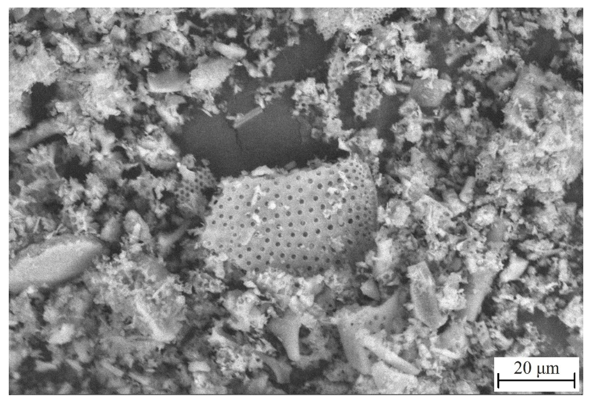
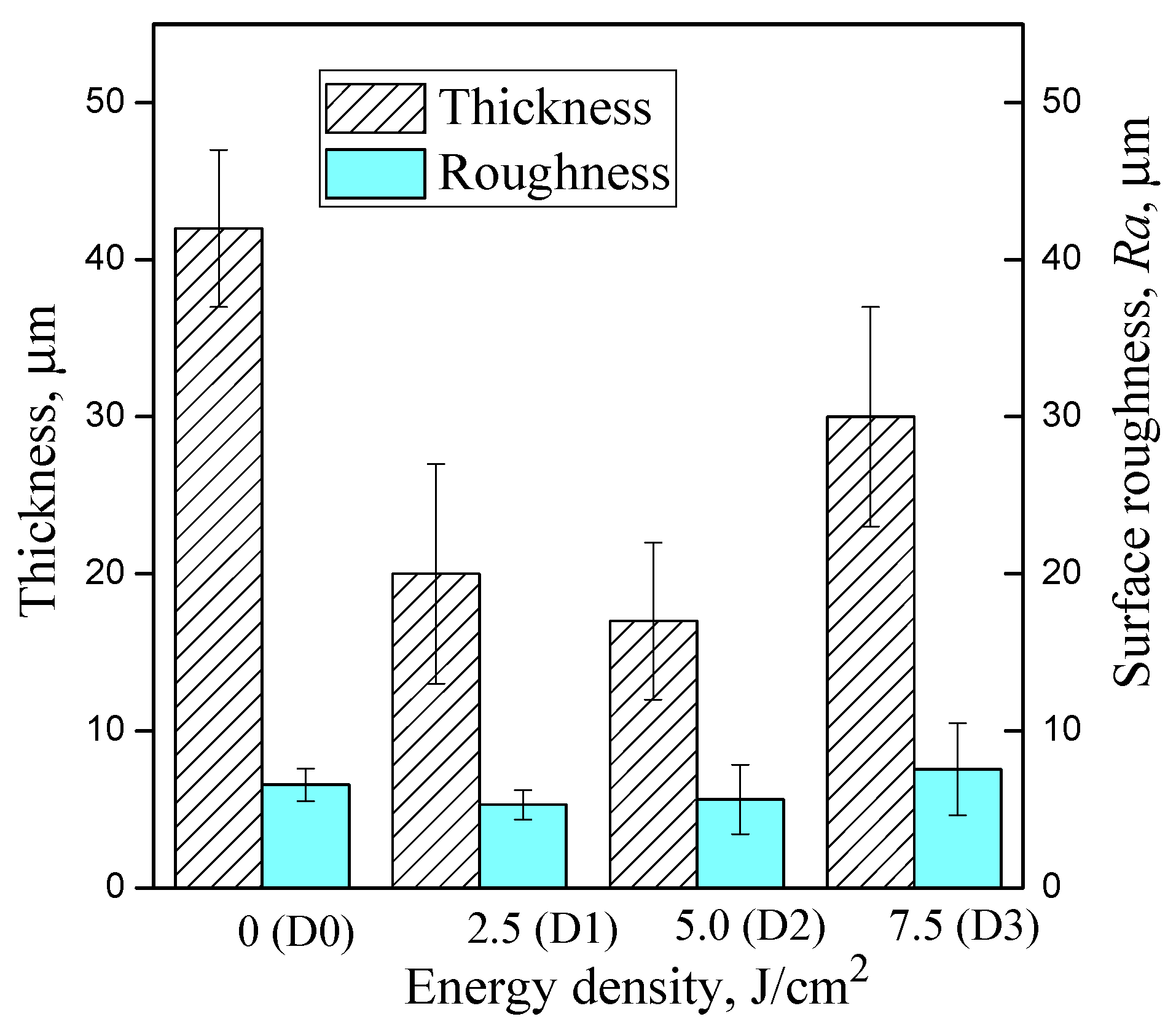
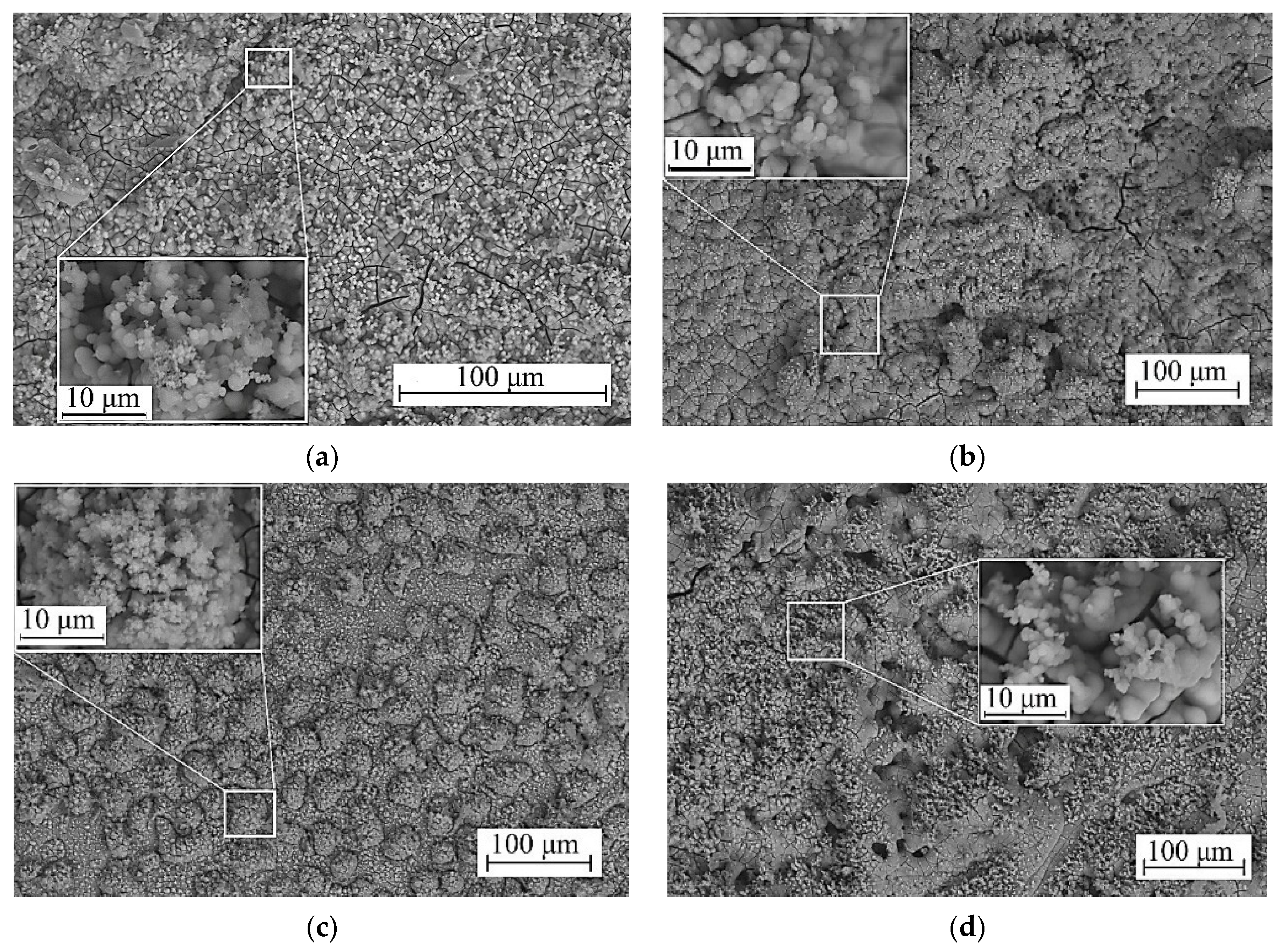
3.1. Morphology of the Coatings

Diatomite is sedimentary rock of biogenic origin formed mainly by fragments of shells (skeletons) of diatoms and radiolarians. The main substance in diatomite is amorphized silica of varying degrees of hydration with SiO2∙nH2O [21]. When examined under a microscope, many fragments of diatom shells can be observed (Figure 1).
The formation of a micro-arc coating in an electrolyte containing diatomite has been studied previously [20,33]. A characteristic feature of these coatings is their high porosity and the presence of diatom algae remnants (Figure 2a). The coatings contain large pores, ranging from 5–10 μm, formed as a result of micro-arc discharges, as well as numerous pores less than 1 μm in size. It is assumed that small pores are formed mainly due to the melting of diatom algae shells into the coating.
As a result of LEHCEB processing, the morphology of the coating surface changes drastically. When the energy density of LEHCEB processing is 2.5 J/cm2 (Figure 2b), the size of large pores in the treated coating decreases to 2–4 µm, and their number increases while becoming more uniformly distributed over the coating surface. In this case, the number of diatom algae particles decreases as they melt into the coating surface.
After the LEHCEB treatment with an energy density equal to 5 J/cm2, a relief consisting of smooth hillocks and porous depressions between them is formed in the coating (Figure 2c). As the energy density is further increased to 7.5 J/cm2, the surface relief becomes more pronounced and the hillocks more convex (Figure 2d).
Figure 3 displays SEM images of cross-sections of the coatings. The initial coating has a thickness of approximately 40 μm (Figure 3a and Figure 4) and a surface roughness Ra of 6.5 μm. The internal structure of the coating is also porous, with the inner layer adjacent to the substrate containing more small pores and the surface layer being denser and including larger pores. After LEHCEB treatment with energy densities of 2.5 and 5.0 J/cm2, the coating thickness is reduced by 50% (Figure 3b,c and Figure 4). Additionally, the roughness of the coatings is reduced to 5.5–5.7 μm, resulting in a smoother surface while maintaining the porous structure. However, when the energy density is increased to 7.5 J/cm2, the roughness of the coating increases sharply to 7.5 μm due to the formation of convex, rounded “hillocks” (Figure 3d and Figure 4).
The rounded formations contain numerous pores, many of which are large in size. Such a structure may be caused by the “intumescence” of the coating during high-energy irradiation. Since the composition of the coating includes fusible components, their sublimation occurs under the action of an electron beams [33]. Some components escape, resulting in pore formation, while others remain obstructed inside the “hillocks”.

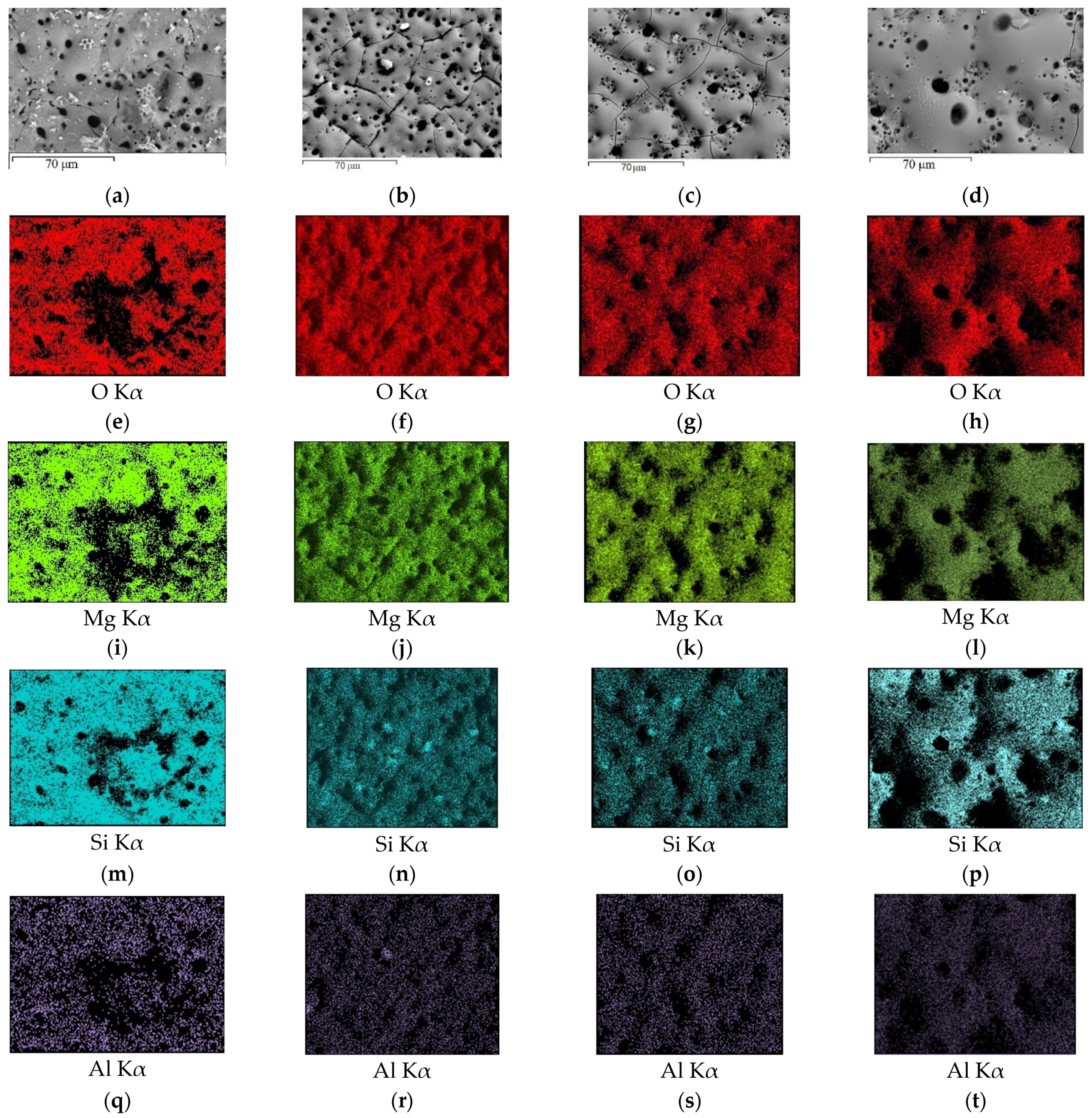
3.2. Elemental and Phase Composition

EDX analysis was used to determine the elemental composition of the coatings (Table 2). The initial coating consists predominantly of O, Mg, and Si. In addition, Na and Al are present, as well as small amounts of K, Ca and Fe, which are part of the clay minerals that are present in diatomite. Table 2 shows that as energy density increases from 2.5 to 7.5 J/cm2 during LEHCEB processing, the Mg content in coatings increases, while Si and impurity elements decrease. This suggests that the intense diffusion of magnesium from the substrate into the coating and interaction with the components of the coating with the formation of amorphous or crystalline compounds occurs.
The element distribution maps show a uniform distribution of all elements over the surface of the coatings, with the only exception being silicon. After LEHCEB processing, its amount on the coating surface decreases. We can observe the accumulation of silicon in the particles of diatom skeletons fused into the coatings (Figure 5n,o). On the Al distribution map, we can identify regions where it coincides with silicon allocations (Figure 5r).
The elemental composition of the cross-section coincides with that of the coating surface (Table 3). As the energy density is increased, the elemental composition changes, following the same pattern as for the coating surface.
The phase composition of the coatings was investigated, revealing their crystalline structure as evidenced by the presence of reflexes of crystalline phases. In addition, a diffuse scattering region could be observed on the X-ray patterns in the range of angles from 10 to 40 degrees (Figure 6) which indicates the formation of amorphous phase in the coatings. The formation of an amorphous crystalline structure is caused by the mechanism and peculiarities of the synthesis of coatings within the micro-arc oxidation method. These irregularities were studied earlier [20].
The main crystalline phase present in both the original D0 coating and the modified D1 and D2 coatings is forsterite (ICDD #34-0189). Forsterite is formed in the coatings as a result of the interaction of amorphous silica (diatomite) with a magnesium substrate [20]. In addition, magnesium oxide MgO (periclase) (ICDD #45-0946) and substrate material Mg (ICDD #35-0821) reflexes were identified on the diffractograms (Figure 6).
An increase in the intensity of reflexes related to forsterite was observed in the diffractograms of the coatings after LEHCEB treatment with an energy density of 2.5–5.0 J/cm2. In addition, new magnesium oxide reflexes appear. The structure of the D3 coating treated with an energy density of 7.5 J/cm2 was significantly different from all the other coatings. The diffractogram of this coating showed intense reflexes corresponding only to the substrate material, magnesium, the intensity of which increased steeply. The other diffraction maxima corresponding to the crystalline phases of the coating became very faint or disappeared completely. This indicates the amorphization of the coating structure. Evidently, the powerful energetic impact of an electron beam with an energy density of 7.5 J/cm2 led to the melting of the basic crystalline phases.

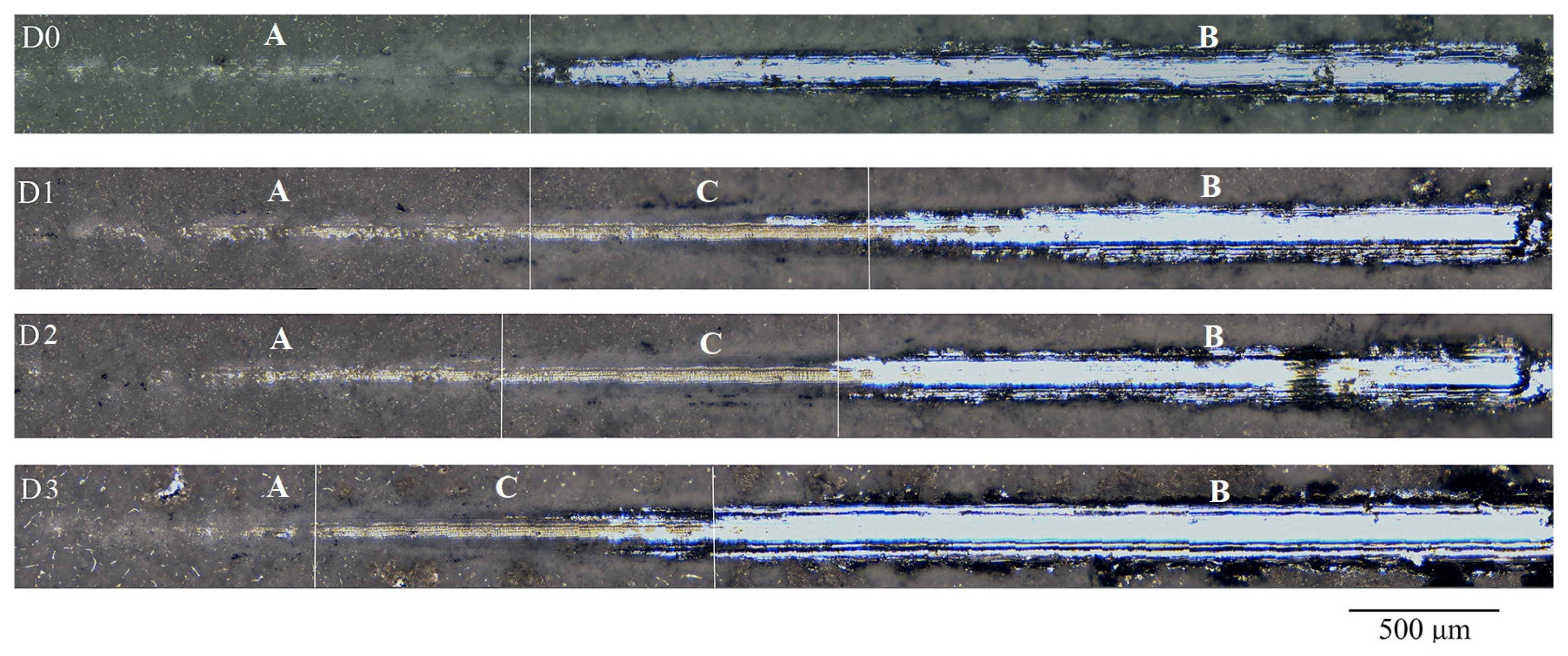
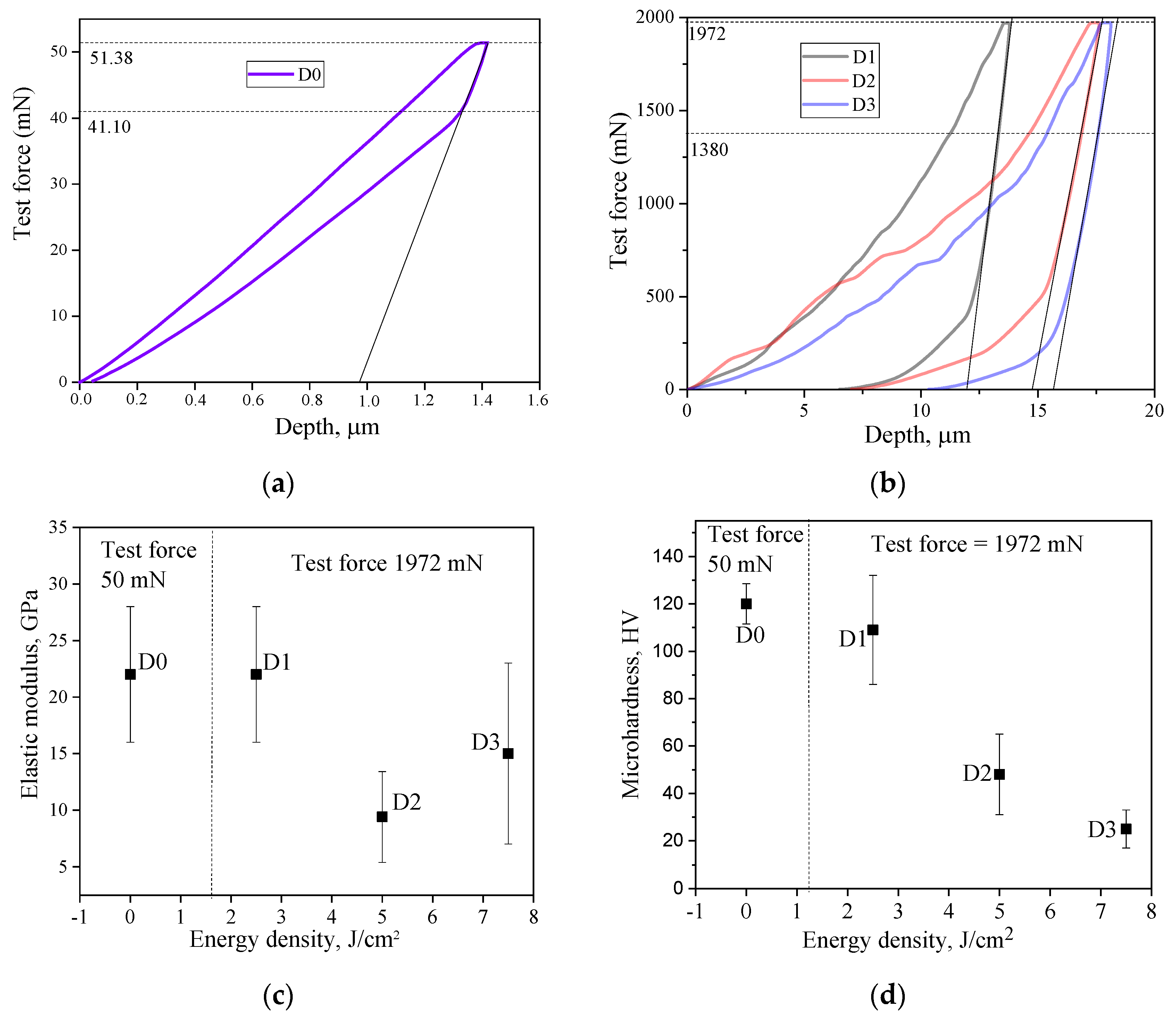
3.3. Mechanical Properties

Studies of the adhesion strength of both the initial and treated samples were carried out using the scratch test method. It was shown that with at all values of energy density, the modification of the coating surface by the LEHCEB treatment increased its adhesion strength. The optical image analysis of scratches produced during scratch testing (Figure 7) illustrates that for the initial samples (D0), the track consists of two distinct zones: the zone of preliminary coating failure (cracking zone A) and the zone of complete coating detachment (peeling zone B—bright section). Conversely, scratch images of samples following LEHCEB processing reveal three distinct zones. An intermediate section (chipping zone C) appears between the cracking zone and the peeling zone. Moreover, the zone of complete coating detachment (bright section) for samples D1, D2, and D3 is reduced compared to the initial one. This zone is the shortest for the D1 sample processed by LEHCEBs with an energy density of 2.5 J/cm2.
This is consistent with the critical load values given in Table 4. Notably, the highest value of 18.8 N was observed for the D1 sample.
The microhardness and modulus of elasticity of the coatings were investigated after LEHCEB treatment with different values of energy density (Figure 8). Since the initial untreated coating, along with high porosity and roughness, was characterized by surface heterogeneity (the presence of fragment inclusions of diatom algae skeletons), it was challenging to obtain consistent results in studying the physical and mechanical properties of the coating. Therefore, given the scatter in the data and the difficulty of conducting these studies, averaged microhardness and modulus of elasticity values were obtained, being representative of this type of coating.
Figure 8 shows the loading curves for the original D0 coating sample (Figure 8a) and for the samples treated with different densities of electron beam energy (Figure 8b). It is noteworthy that the loading curves for the LEHCEB-treated coating samples were obtained at loads significantly higher than those for the original sample. Thus, it should be concluded that the strength properties of the coatings greatly improve as a result of LEHCEB treatment. The D1 coating exhibited the highest value of elastic modulus equal to 22 GPa (Figure 8c). As the energy density of the LEHCEB increased, the values of the modulus of elasticity for the treated coatings decreased; however, there is also considerable variability in the data.
After the electron beam treatment, the D1 coating demonstrated a maximum microhardness value of 109 HV. When the energy density of the electron beam was increased from 2.5 to 7.5 J/cm2, the microhardness of the coatings decreased to 25 HV. In part, this can be attributed to a change in the phase composition of the coatings.
Compared to the initial coating (D0), after LEHCEB processing at 2.5 J/cm2 and 5.0 J/cm2, an increase in the intensity of the reflexes related to forsterite and the appearance of new diffraction peaks indicative of magnesium oxide (Figure 6) were observed in D1 and D2 coatings, which indicates an increase in the crystallinity of these coatings. However, with further increase in the energy density up to 7.5 J/cm2, the reflexes of the main crystalline phases disappeared, and the reflexes specific to the magnesium substrate material intensified as the coating became thinner. This diffraction pattern indicates a decrease in the crystallinity of the coating and its partial amorphization.
The optimal strength properties of the D1 coating can also be explained by its distinctive surface morphology. The micrograph of the D1 coating (Figure 2b) shows a more uniform distribution of pores of approximately the same size across the surface of the sample.

3.4. Corrosion and Biological Properties

3.4.1. Electrochemical Properties

The main objective of applying coatings to magnesium alloys is to improve their anti-corrosion properties. Therefore, it is necessary to conduct a comparative study of the electrochemical corrosion and bioresorption rates of pure alloys and coated samples in a model biological fluid to effectively characterize these coatings.
Potentiodynamic curves were obtained and electrochemical parameters such as corrosion potential, corrosion current density, and polarization resistance were measured. The arrangement of the polarization curves on the plot of corrosion potential vs. corrosion current density (Figure 9) indicates that all coatings act protectively on the magnesium alloys and significantly improve their corrosion properties.
This is evidenced by the increased corrosion potential values of coated samples in comparison to the magnesium alloy, a decrease in corrosion current density by two to five orders of magnitude, and an increase in polarization resistance by one to five orders of magnitude (Table 5). Furthermore, it should be noted that the anti-corrosion properties of LEHCEB-treated coatings exceed those of untreated coatings, since the corrosion current density decreased by one to three orders of magnitude and the polarization resistance increased by two to four orders of magnitude. Notably, the D2 coating has a minimum value of corrosion current density equal to 4.6 × 10⁻¹⁰ A·cm−2 and a maximum value of polarization resistance equal to 1.4 × 10⁸ Ω·cm2.

3.4.2. Immersion in Simulated Body Fluid (SBF)

After seven days of incubation in an SBF solution, a dense calcium phosphate layer with convex spherical granules formed on the surface of all coatings (Figure 10). This structure is typical of amorphous calcium phosphates that usually form in the initial stages of biomineralization. A similar result was obtained by Akram et al. [39] after 168 h of immersion in an SBF solution. The formation of smaller crystals was observed on the surface of the granules, indicating subsequent recrystallization and growth of crystalline hydroxyapatite. The calcium phosphate layer on the surface of LEHCEB-treated coatings was characterized by a more pronounced relief compared to the untreated coating.
The elemental composition of the coatings after the immersion is presented in Table 6. These data show that in addition to O, Mg, and Si, the coatings additionally contain Ca and P precipitated from the SBF solution.
These data confirm the formation of a calcium phosphate layer under conditions that emulate the human body environment. The Ca/P ratio for untreated coatings is 1.43, whereas for LEHCEB-treated coatings, it ranges from 1.54 to 1.67, indicating a more intense process of biomineralization and crystallization of hydroxyapatite. The highest values of Ca/P ratio, equal to 1.67 and 1.65, were established for coatings D1 and D2, respectively.

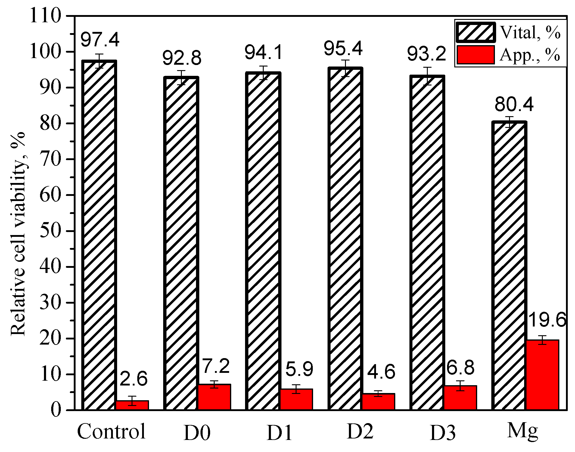
3.4.3. In Vitro Cytotoxicity

The toxicity of samples in relation to test cell cultures is the primary criterion for evaluating the possibility of their use in biomedical applications. Toxicity studies of the synthesized coatings using flow cytometry allowed us to evaluate their effect on the viability of the NIH/3T3 cell line (Figure 11).
The data obtained showed that all coating samples have no significant effect on cell line viability and are non-toxic according to ISO 10993-5-2009 [40] “Medical devices. Biological evaluation of medical devices. Part 5: Tests for in vitro cytotoxicity”, as the decrease in viability does not exceed 5% relative to the negative control. At the same time, samples D0 and D3 have a more pronounced effect on cell activity. The highest number of apoptotic cells (7.2%) was detected after incubation with the D0 sample. After processing the coatings with LEHCEB at the energy densities of 2.5 J/cm2 and 5.0 J/cm2 (samples D1 and D2), the number of apoptotic cells decreased to 5.9% and 4.6%, respectively. However, when the energy density was further increased to 7.5 J/cm2 (sample D3), the number of apoptotic cells increased to 6.8%. In addition, the largest number of apoptotic cells (19.6%) was observed after their interaction with pure magnesium alloy.

3.4.4. Assessment of Lipid Peroxidation

Lipid peroxidation (LPO) in cellular membranes can cause severe membrane damage and potential cell death [41]. The intensity of LPO was determined by measuring the level of TBA-active products such as bityrosine and malondialdehyde (MDA), which are widely used as markers of lipid peroxidation and oxidative stress [42].
The results (Table 7) showed changes in the parameters for both treated and untreated samples compared to the control. The most significant increase was observed for induced TBA products. The induced TBA product content increased by 2.6 and 1.4 times for the D0 and D2 samples, respectively, compared to the control. The bityrosine fluorescence was significantly increased in homogenates for the D0 sample (Table 7). We found that the treatment of samples could inhibit the oxidative stress reaction and minimize tissue damage.
The most important enzymes involved in the neutralization of reactive oxygen species are catalase and superoxide dismutase (SOD) [43]. Another enzyme associated with the oxidation processes is cathepsin D. It has been proven that the increase in cathepsin D activity serves as a reliable diagnostic and prognostic criterion of the nature and depth of changes in the LPO.
The catalase activity and SOD remained practically unchanged for the samples (Table 7). The content of total cathepsin D was increased only for the sample D0 compared with the treated sample D2 and control. An increase in cathepsin D activity indicates a probable cytotoxic effect of the sample.
Thus, in the presence of both samples, an activation of POL was observed without an increase in the activity of antioxidant enzymes. However, this was much more pronounced for the untreated sample D0.

4. Discussion

Micro-arc coatings are well established and have been widely used in many fields of engineering and medicine over the past decade [44]. These coatings exhibit a ceramic-like nature combined with distinctive microporous surface morphology, offering a broad spectrum of functional properties [45]. The MAO method, due to its unique characteristics, can be used to synthesize coatings with integrated ions and particles, enhancing corrosion resistance, wear resistance, or imparting bioactive properties to treated surfaces [18,19,46]. The latter aspect is of particular interest in the case of materials for bone-contact implantable devices, since MAO treatment allows enhanced osteoconductive/osteoinductive and antibacterial properties to be imparted to the implant surfaces, which promotes further osseointegration [47]. However, the porous structure of micro-arc coatings has a negative effect on their strength and corrosion properties, while high relief and surface roughness are not always favorable for cell adhesion [33].
The scientific literature contains data on various methods of surface modification of micro-arc coatings in order to enhance their osteogenic, anticorrosive, and strength properties. These methods include hydrothermal treatment [48], ultraviolet irradiation, and exposure to diffuse discharge plasma [49]. Pulsed electron irradiation (PEI) is another proven and effective method that allows varying the properties of micro-arc coatings [33].
In the presented work, the LEHCEB method was used to modify the surface of diatomite-based coatings synthesized on magnesium alloy by the MAO method. It was found that varying the electron beam energy density within a range of 2.5–7.5 J/cm2 while keeping other LEHCEB parameters constant significantly affects the surface morphology as well as the key physicochemical and functional characteristics. At an energy density of 2.5 J/cm2, the initial rough and porous surface of micro-arc coating D0, which included diatom algae particles, became smoother and more uniformly porous (D1). However, as the energy density increased further, pore accumulation in certain areas (D2), coating sublimation, and internal porosity increase; intumescence (D3) was also observed. A specific relief was formed from convex, rounded “hillocks” and the depressions between them. However, there are research results [50,51] showing that similar structure formation processes also occur on metal surfaces or in thin films as a result of high-energy exposure. Proskurovsky et al. [28] describe the formation of microcraters via irradiation upon reaching the melting threshold.
Exposure to an electron beam with an energy density between 2.5–5.0 J/cm2 promoted an increase in the content of crystalline phases in the coatings of forsterite (Mg2SiO4) and periclase (MgO). However, at an energy density equal to 7.5 J/cm2, the structure of the coatings became less crystalline. It is known from the literature [34,35] that the ultrafast heating and melting of the surface layer occurs under different modes when varying electron beam energy density, pulse duration and frequency, and the number of pulses.
Exposure to the electron beam had a primarily positive effect on the mechanical properties of the coatings. The microhardness and modulus of elasticity values of the irradiated coatings were measured at a load four times higher than that of the untreated coating (D0). The adhesion strength of the coating treated at an energy density of 2.5 J/cm2 (critical load = 18.8 N) significantly exceeded the adhesion strength of the untreated D0 coating (critical load = 7.6 N) due to the formation of a uniformly porous structure and an increase in the content of crystalline phases in the coating.
The corrosion resistance of the treated coatings significantly improved compared to both the pure Mg alloy and the initial coating. The D0 coating exhibited corrosion current and polarization resistance values of 1.8 × 10⁻⁷ A·cm−2 and 8.8 × 10⁴ Ω·cm2, respectively, indicating its effectiveness in preventing corrosion. When subjected to an electron beam with an energy density in the range of 2.5–7.5 J/cm2, the corrosion resistance of the coatings increased, and coating D2 showed the best corrosion resistance with corrosion current and polarization resistance values equal to 4.6 × 10⁻¹⁰ A·cm−2 and 1.4 × 10⁸ Ω·cm2, respectively.
After 7 days of incubation in SBF solution, all coatings (D0, D1, D2, D3) formed a layer of amorphous calcium phosphate, as verified by the elemental analysis results. The treated coatings exhibited a higher Ca/P ratio with values of 1.67 and 1.65 for coatings D1 and D2, respectively, which are similar to the value for hydroxyapatite.
The in vitro cytotoxicity of the coatings was studied. None of the coatings had a toxic effect on the NIH/3T3 cell culture. The highest number of viable cells (95.4%) and the lowest number of apoptotic cells (4.6%) were observed for coating D2 (5.0 J/cm2). Determining the intensity of lipid peroxidation (LPO) as well as levels of TBA-active products, bityrosine, and malondialdehyde (MDA)—all of which are commonly used as markers of oxidative stress [42]—revealed that the application of an electron beam with an energy density of 5 J/cm2 (D2) to the coating effectively curbs the oxidative stress response and mitigates the inflammatory process. Cathepsin D is also an enzyme associated with oxidative processes that shows the nature and magnitude of changes in LPO [43]. An increase in cathepsin D activity may indicate a cytotoxic effect of the sample. The study revealed that the content of total cathepsin D was higher only for the untreated sample D0, as opposed to the treated sample D2 and the control.

5. Conclusions

It was established that modification of micro-arc coatings by the LEHCEB technique has a positive effect on their mechanical, corrosion, and biological properties. However, the electron beam energy density should be within the range of 2.5–5.0 J/cm2 in order to obtain coatings with a set of optimal properties. Thus, we propose a straightforward, cost-effective method based on a natural material for modifying the surface of coatings, which can significantly improve the corrosion resistance and biocompatibility of magnesium implants.

Author Contributions

Conceptualization, M.B.S. and A.D.K.; methodology, M.B.S., A.D.K. and K.V.I.; software, M.A.K., P.V.U. and N.A.L.; validation, O.V.B., O.V.K. and K.V.I.; formal analysis, M.B.S., A.D.K., P.V.U. and K.V.I.; investigation, E.S.D., N.A.L. and O.V.B.; resources, O.V.K. and Y.P.S.; data curation, M.B.S., M.A.K., A.D.K. and K.V.I.; writing—original draft preparation, M.B.S. and A.D.K.; writing—review and editing, M.B.S., A.D.K., E.S.D. and K.V.I.; visualization, N.A.L., P.V.U. and A.D.K.; supervision, O.V.K. and Y.P.S.; project administration, M.B.S.; funding acquisition, Y.P.S. All authors have read and agreed to the published version of the manuscript.

Funding

The work was performed according to a Government research assignment for ISPMS SB RAS, project FWRW-2021-0007.

Data Availability Statement

The original contributions presented in the study are included in the article, further inquiries can be directed to the corresponding author.

Acknowledgments

Research into elastoplastic properties and microhardness was carried out using the equipment of the CSU NMNT TPU, supported by the RF MES, project #075 15 2021 710. The authors express their appreciation for the valuable contributions of A.I. Tolmachev from the Institute of Strength Physics and Materials Science SB RAS (Tomsk, Russia) and for his assistance in the preparation of experimental materials. The experimental research was performed using equipment from the Shared Use Centre “Nanotech” of the ISPMS SB RAS.

Conflicts of Interest

The authors declare no conflicts of interest.

References

  1. Heimann, R.B. Magnesium alloys for biomedical application: Advanced corrosion control through surface coating. Surf. Coat. Technol. 2021, 405, 126521. [Google Scholar] [CrossRef]
  2. Tsakiris, V.; Tardei, C.; Clicinschi, F.M. Biodegradable Mg alloys for orthopedic implants—A review. J. Magnes. Alloy. 2021, 9, 1884–1905. [Google Scholar] [CrossRef]
  3. Raman, R.K.; Harandi, S.E. Resistance of magnesium alloys to corrosion fatigue for biodegradable implant applications: Current status and challenges. Materials 2017, 10, 1316. [Google Scholar] [CrossRef] [PubMed]
  4. Comba, A.; Cicek, B.; Comba, B.; Sancak, T.; Akveran, G.A.; Sun, Y.; Elen, L.; Afshar, M.T. Investigation of in-vitro biocompatibility and in-vivo biodegradability of AM series Mg alloys. Mater. Technol. 2022, 37, 2819–2831. [Google Scholar] [CrossRef]
  5. Kamrani, S.; Fleck, C. Biodegradable magnesium alloys as temporary orthopaedic implants: A Review. BioMetals 2019, 32, 185–193. [Google Scholar] [CrossRef] [PubMed]
  6. Maier, P.; Hort, N. Magnesium alloys for biomedical applications. Metals 2020, 10, 1328. [Google Scholar] [CrossRef]
  7. Saha, S.; Lestari, W.; Dini, C.; Sarian, M.N.; Hermawan, H.; Barão, V.A.R.; Sukotjo, C.; Takoudis, C. Corrosion in Mg-alloy biomedical implants—The strategies to reduce the impact of the corrosion inflammatory reaction and microbial activity. J. Magnes. Alloy. 2022, 10, 3306–3326. [Google Scholar] [CrossRef]
  8. Molaei, M.; Fattah-alhosseini, A.; Nouri, M.; Nourian, A. Systematic optimization of corrosion, bioactivity, and biocompatibility behaviors of calcium-phosphate plasma electrolytic oxidation (PEO) coatings on titanium substrates. Ceram. Int. 2022, 48, 6322–6337. [Google Scholar] [CrossRef]
  9. Darband, G.B.; Aliofkhazraei, M.; Hamghalam, P.; Valizade, N. Plasma electrolytic oxidation of magnesium and its alloys: Mechanism, properties and applications. J. Magnes. Alloy. 2017, 5, 74–132. [Google Scholar] [CrossRef]
  10. Wala, M.; Łubiarz, D.; Waloszczyk, N.; Simka, W. Plasma electrolytic oxidation of titanium in Ni and Cu hydroxide suspensions towards preparation of electrocatalysts for urea oxidation. Materials 2023, 16, 2191. [Google Scholar] [CrossRef]
  11. Santos-Coquillat, A.; Esteban-Lucia, M.; Martinez-Campos, E.; Mohedano, M.; Arrabal, R.; Blawert, C.; Zheludkevich, M.L.; Matykina, E. PEO coatings design for Mg-Ca alloy for cardiovascular stent and bone regeneration applications. Mater. Sci. Eng. C 2019, 105, 110026. [Google Scholar] [CrossRef]
  12. Ghasemi, A.; Kamrani, S.; Hübler, D.; Fleck, C. Corrosion behavior of porous magnesium coated by plasma electrolytic oxidation in simulated body fluid. Mater. Corros. 2019, 70, 1561–1569. [Google Scholar] [CrossRef]
  13. Liu, S.; Li, Z.; Yu, Q.; Qi, Y.; Peng, Z.; Liang, J. Dual self-healing composite coating on magnesium alloys for corrosion protection. Chem. Eng. J. 2021, 424, 130551. [Google Scholar] [CrossRef]
  14. Grebņevs, V.; Leśniak-Ziółkowska, K.; Wala, M.; Dulski, M.; Altundal, Ș.; Dutovs, A.; Avotiņa, L.; Erts, D.; Viter, R.; Vīksna, A.; et al. Modification of physicochemical properties and bioactivity of oxide coatings formed on Ti substrates via plasma electrolytic oxidation in crystalline and amorphous calcium phosphate particle suspensions. Appl. Surf. Sci. 2022, 598, 153793. [Google Scholar] [CrossRef]
  15. Prosolov, K.A.; Lastovka, V.V.; Belyavskaya, O.A.; Lychagin, D.V.; Schmidt, J.; Sharkeev, Y.P. Tailoring the surface morphology and the crystallinity state of Cu- and Zn-substituted hydroxyapatites on Ti and Mg-based alloys. Materials 2020, 13, 4449. [Google Scholar] [CrossRef]
  16. Sasikumar, Y.; Kumar, A.M.; Babu, R.S.; Rahman, M.M.; Samyn, L.M.; de Barros, A.L.F. Biocompatible hydrophilic brushite coatings on AZX310 and AM50 alloys for orthopaedic implants. J. Mater. Sci. Mater. Medic. 2018, 29, 123. [Google Scholar] [CrossRef]
  17. Shadanbaz, S.; Dias, G.J. Calcium phosphate coatings on magnesium alloys for biomedical applications: A Review. Acta Biomater. 2012, 8, 20–30. [Google Scholar] [CrossRef]
  18. Molaei, M.; Nouri, M.; Babaei, K.; Fattah-Alhosseini, A. Improving surface features of PEO coatings on titanium and titanium alloys with zirconia particles: A review. Surf. Interfaces 2021, 22, 100888. [Google Scholar] [CrossRef]
  19. Fattah-alhosseini, A.; Chaharmahali, R.; Babaei, K. Effect of particles addition to solution of plasma electrolytic oxidation (PEO) on the properties of PEO coatings formed on magnesium and its alloys: A review. J. Magnes. Alloy. 2020, 8, 799–818. [Google Scholar] [CrossRef]
  20. Kashin, A.D.; Sedelnikova, M.B.; Chebodaeva, V.V.; Uvarkin, P.V.; Luginin, N.A.; Dvilis, E.S.; Kazmina, O.V.; Sharkeev, Y.P.; Khlusov, I.A.; Miller, A.A.; et al. Diatomite-based ceramic biocoating for magnesium implants. Ceram. Int. 2022, 48, 28059–28071. [Google Scholar] [CrossRef]
  21. Fu, Q.; Liu, Q.; Li, L.; Li, X.; Gu, H.; Sheng, B. Effect of doping different Si source on Ca-P bioceramic coating fabricated by laser cladding. J. Appl. Biomater. Funct. Mater. 2020, 18, 1–9. [Google Scholar] [CrossRef]
  22. Mohammadi, H.; Hafezi, M.; Nezafati, N.; Heasarki, S.; Nadernezhad, A.; Ghazanfari, S.M.H.; Sepantafar, M. Bioinorganics in bioactive calcium silicate ceramics for bone tissue repair: Bioactivity and biological properties. J. Ceram. Sci. Technol. 2014, 5, 1–12. [Google Scholar]
  23. Pan, Y.; Chen, C.; Wang, D.; Huang, D. Dissolution and precipitation behaviors of silicon-containing ceramiccoating on Mg–Zn–Ca alloy in simulated body fluid. Colloids Surf. B Biointerfaces 2014, 122, 746–751. [Google Scholar] [CrossRef]
  24. Sainz, M.A.; Pena, P.; Serena, S.; Caballero, A. Influence of design on bioactivity of novel CaSiO3–CaMg(SiO3)2 bioceramics: In vitro simulated body fluid test and thermodynamic simulation. Acta Biomater. 2010, 6, 2797–2807. [Google Scholar] [CrossRef]
  25. Ni, S.; Chang, J.; Chou, L.; Zhai, W. Comparison of osteoblast-like cell responses to calcium silicate and tricalcium phosphate ceramics in vitro. J. Biomed. Mater. Res. Part B Appl. Biomater. 2007, 80, 174–183. [Google Scholar] [CrossRef] [PubMed]
  26. Bakhsheshi-Rad, H.R.; Najafinezhad, A.; Hamzah, E.; Ismail, A.F.; Berto, F.; Chen, X. Clinoenstatite/Tantalum Coating for Enhancement of Biocompatibility and Corrosion Protection of Mg Alloy. J. Funct. Biomater. 2020, 11, 26. [Google Scholar] [CrossRef] [PubMed]
  27. Proskurovsky, D.I.; Rotshtein, V.P.; Ozur, G.E.; Markov, A.B.; Nazarov, D.S.; Shulov, V.A.; Ivanov, Y.F.; Buchheit, R.G. Pulsed electron-beam technology for surface modification of metallic materials. J. Vac. Sci. Technol. A. 1998, 16, 2480–2488. [Google Scholar] [CrossRef]
  28. Proskurovsky, D.I.; Rotshtein, V.P.; Ozur, G.E.; Ivanov, Y.F.; Markov, A.B. Physical foundations for surface treatment of materials with low energy, high current electron beams. Surf. Coat. Technol. 2000, 125, 49–56. [Google Scholar] [CrossRef]
  29. Pfeifenberger, M.J.; Milassin, G.; Hohenwarter, A.; Putz, B.; Semprimoschnig, C.O.A.; Pippan, R. Electron irradiation effects on strength and ductility of polymer foils studied by femtosecond laser-processed micro-tensile specimens. Materials 2019, 12, 1468. [Google Scholar] [CrossRef]
  30. Yu, B.-H.; Ovcharenko, V.E.; Ivanov, K.V.; Mokhovikov, A.A.; Zhao, Y.-H. Effect of surface layer structural-phase modification on tribological and strength properties of a TiC–(Ni–Cr) Metal Ceramic Alloy. Acta Metall. Sin. 2018, 31, 547–551. [Google Scholar] [CrossRef]
  31. Ozur, G.; Proskurovsky, D.; Rotshtein, V.; Markov, A. Production and application of low-energy, high-current electron beams. Laser Part. Beams 2003, 21, 157–174. [Google Scholar] [CrossRef]
  32. Ozur, G.E.; Proskurovsky, D.I. Generation of low-energy high-current electron beams in plasma-anode electron guns. Plasma Phys. Rep. 2018, 44, 18–39. [Google Scholar] [CrossRef]
  33. Sedelnikova, M.B.; Ivanov, K.V.; Ugodchikova, A.V.; Kashin, A.D.; Uvarkin, P.V.; Sharkeev, Y.P.; Tolkacheva, T.V.; Tolmachev, A.I.; Schmidt, J.; Egorkin, V.S.; et al. The effect of pulsed electron irradiation on the structure, phase composition, adhesion and corrosion properties of calcium phosphate coating on Mg0.8Ca alloy. Mater. Chem. Phys. 2023, 294, 126996. [Google Scholar] [CrossRef]
  34. Węglowski, M.S.; Śliwiński, P.; Dymek, S.; Kalemba-Rec, I.; Kapuściński, M.; Wrona, A.; Kustra, K. A comprehensive study on the microstructure of plasma spraying coatings after electron beam remelting. J. Phys. Conf. Ser. 2023, 2443, 012005. [Google Scholar] [CrossRef]
  35. Ivanov, K.V.; Voronov, A.V. Evolution of morphology, microstructure and phase composition of zirconia thin coating on copper as a result of low energy high current pulsed electron beam irradiation. Surf. Coat. Technol. 2023, 456, 129257. [Google Scholar] [CrossRef]
  36. Kokubo, T.; Takadama, H. How useful is SBF in predicting in vivo bone bioactivity? Biomaterials 2006, 27, 2907–2915. [Google Scholar] [CrossRef] [PubMed]
  37. Janero, D.R. Malondialdehyde and thiobarbituric acid-reactivity as diagnostic indices of lipid peroxidation and peroxidative tissue injury. Free Radic. Biol. Med. 1990, 9, 515–540. [Google Scholar] [CrossRef]
  38. Hinton, R.H.; Burge, M.L.E.; Hartman, G.C. Sucrose interference in the assay of enzymes and protein. Anal. Biochem. 1969, 29, 248–256. [Google Scholar] [CrossRef]
  39. Akram, W.; Zahid, R.; Usama, R.M.; AlQahtani, S.A.; Dahshan, M.; Basit, M.A.; Yasir, M. Enhancement of antibacterial properties, surface morphology and in vitro bioactivity of hydroxyapatite-zinc oxide nanocomposite coating by electrophoretic deposition technique. Bioengineering 2023, 10, 693. [Google Scholar] [CrossRef]
  40. ISO 10993-5:2009; Biological Evaluation of Medical Devices. Part 5: Tests for In Vitro Cytotoxicity. International Organization for Standardization: Geneva, Switzerland, 2022.
  41. Yang, H.; Zhou, M.; Li, H.; Wei, T.; Tang, C.; Zhou, Y.; Long, X. Effects of low-level lipid peroxidation on the permeability of nitroaromatic molecules across a membrane: A computational study. ACS Omega 2020, 5, 4798–4806. [Google Scholar] [CrossRef]
  42. Lisanti, M.P.; Martinez-Outschoorn, U.E.; Lin, Z.; Pavlides, S.; Whitaker-Menezes, D.; Pestell, R.G.; Howell, A.; Sotgia, F. Hydrogen peroxide fuels aging, inflammation, cancer metabolism and metastasis: The seed and soil also needs “fertilizer”. Cell Cycle 2011, 10, 2440–2449. [Google Scholar] [CrossRef]
  43. Glorieux, C.; Calderon, P.B. Catalase, a remarkable enzyme: Targeting the oldest antioxidant enzyme to find a new cancer treatment approach. Biol. Chem. 2017, 398, 1095–1108. [Google Scholar] [CrossRef]
  44. Aliofkhazraei, M.; Macdonald, D.D.; Matykina, E.; Parfenov, E.V.; Egorkin, V.S.; Curran, J.A.; Troughton, S.C.; Sinebryukhov, S.L.; Gnedenkov, S.V.; Lampke, T.; et al. Review of plasma electrolytic oxidation of titanium substrates: Mechanism, properties, applications and limitations. Appl. Surf. Sci. Adv. 2021, 5, 100121. [Google Scholar] [CrossRef]
  45. Simchen, F.; Sieber, M.; Kopp, A.; Lampke, T. Introduction to plasma electrolytic oxidation—An overview of the process and applications. Coatings 2020, 10, 628. [Google Scholar] [CrossRef]
  46. Polunin, A.V.; Cheretaeva, A.O.; Borgardt, E.D.; Rastegaev, I.A.; Krishtal, M.M.; Katsman, A.V.; Yasnikov, I.S. Improvement of oxide layers formed by plasma electrolytic oxidation on cast Al–Si alloy by incorporating TiC nanoparticles. Surf. Coat. Technol. 2021, 423, 127603. [Google Scholar] [CrossRef]
  47. He, J.; Zhang, B.; Shao, L.; Feng, W.; Jiang, L.; Zhao, B. Biomechanical and histological studies of the effects of active zinc-coated implants by plasma electrolytic oxidation method on osseointegration in rabbit osteoporotic jaw. Surf. Coat. Technol. 2020, 396, 125848. [Google Scholar] [CrossRef]
  48. Kim, S.Y.; Kim, Y.K.; Ryu, M.H.; Bae, T.S.; Lee, M.H. Corrosion resistance and bioactivity enhancement of MAO coated Mg alloy depending on the time of hydrothermal treatment in Ca-EDTA solution. Sci. Rep. 2017, 7, 9061. [Google Scholar] [CrossRef] [PubMed]
  49. Chebodeva, V.V.; Komarova, E.G.; Erofeev, M.V.; Ripenko, V.S.; Sharkeev, Y.P. Effect of UV irradiation and diffuse plasma on surface properties of micro-arc calcium phosphate coatings. J. Phys. Conf. Ser. 2019, 1393, 012077. [Google Scholar] [CrossRef]
  50. Qin, Y.; Dong, C.; Wang, X.; Hao, S.; Wu, A.; Zou, J.; Liu, Y. Temperature profile and crater formation induced in high-current pulsed electron beam processing. J. Vac. Sci. Technol. A 2003, 21, 1934–1938. [Google Scholar] [CrossRef]
  51. Dun, A.; Wei, J.; Gan, F. Marangoni effect induced micro/nano-patterning on Sb2Te3 phase change thin film by laser pulse. Appl. Phys. A. 2011, 103, 139–147. [Google Scholar] [CrossRef]
Figure 1. SEM images of the initial diatomite powder.
Metals 14 00248 g001
Figure 2. SEM of the surface morphology of the D0 (a), D1 (b), D2 (c) and D3 (d) coatings.
Metals 14 00248 g002
Figure 3. SEM images of the cross-section of the coatings D0 (a), D1 (b), D2 (c), and D3 (d).
Metals 14 00248 g003
Figure 4. Coating thickness and surface roughness Ra in relation to the energy density of LEHCEB processing.
Metals 14 00248 g004
Figure 5. SEM images (ad) and element distribution maps in the D0 (e,i,m,q), D1 (f,j,n,r), D2 (g,k,o,s) and D3 (h,l,p,t) coatings.
Metals 14 00248 g005
Figure 6. X-ray diffraction patterns of the diatomite coatings before (D0) and after the LEHCEB treatment (D1, D2 and D3).
Metals 14 00248 g006
Figure 7. Optical images of coating samples after scratch testing. D0—initial coating, D1, D2 and D3—the coatings after the LEHCEB treatment; A—cracking zone, B—peeling zone, C—chipping zone.
Metals 14 00248 g007
Figure 8. Determination of the elastic modulus of the coatings D0 (a) and D1, D2, D3 (b); elastic modulus (c) and microhardness (d) of the coatings D0, D1, D2, and D3 versus energy density of LEHCEB treatment.
Metals 14 00248 g008
Figure 9. Potentiodynamic polarization curves for the initial Mg alloy and for the coatings before (D0) and after LEHCEB treatment (D1, D2 and D3).
Metals 14 00248 g009
Figure 10. SEM images of the surface morphology of the D0 (a), D1 (b), D2 (c) and D3 (d) coatings after immersion in the SBF solution. Magnification of the main images ×1000 (a), ×500 (bd), magnification of the marked fragments ×10,000 (ad).
Metals 14 00248 g010
Figure 11. NIH/3T3 cells’ viability after incubation according to the results of research via flow cytometry: viable cells—striped columns, apoptotic cells—red columns.
Metals 14 00248 g011
Table 1. Parameters of MAO and LEHCEB processing.
Sample NumberVoltage of MAO Process, VDuration of MAO Process, MinEnergy Density of LEHCEB, J/cm2Number of Pulses
D04005
D140052.55
D2400555
D340057.55
Table 2. Elemental composition of the coatings, at. %.
ElementsD0D1D2D3
O Kα61.7 ± 0.160.0 ± 0.459.5 ± 0.955.4 ± 0.1
Na Kα1.60.00.00.4
Mg Kα16.0 ± 0.0923.6 ± 0.226.2 ± 0.227.1 ± 0.1
Al Kα1.01.51.51.0
Si Kα19.3 ± 0.0714.5 ± 0.113.8 ± 0.115.5 ± 0.5
K Kα0.10.030.00.02
Ca Kα0.20.10.10.04
Fe Kα0.30.20.10.6
Table 3. Elemental composition of the coatings cross-sections in at. %.
ElementsD0D1D2D3
O Kα62.8 ± 0.159.1 ± 0.159.8 ± 0.760.03 ± 0.8
Na Kα0.10.60.150.63
Mg Kα17.9 ± 0.0724.1 ± 0.0523.6 ± 0.0824.64 ± 0.09
Al Kα1.31.01.10.97
Si Kα17.5 ± 0.0315.0 ± 0.0715.2 ± 0.0313.53 ± 0.08
K Kα0.120.150.160.03
Ca Kα0.070.040.040.1
Fe Kα0.370.050.050.07
Table 4. Critical load, N.
SampleScratch NumberCritical Load, NAverage
Critical Load, N
D017.257.6 ± 0.3
27.28
38.23
D1120.0818.8 ± 0.65
217.62
318.61
D2118.8917.1 ± 1.2
217.34
315.06
D3112.8713.3 ± 0.3
213.97
313.08
Table 5. Electrochemical parameters of the samples after LEHCEB processing.
SampleEc, VJc,
A·cm−2
Rp,
Ω·cm2
Mg alloy−1.425.7 × 10−51.7 × 10³
D0−0.981.8 × 10−78.8 × 10⁴
D1−0.167.3 × 10−81.1 × 10⁶
D2−0.514.6 × 10−101.4 × 10⁸
D3−0.292.8 × 10−81.8 × 10⁶
Table 6. Elemental composition of the coatings after immersion in the SBF solution at. %.
ElementsD0D1D2D3
O Kα62.8 ± 1.568.9 ± 1.466.7 ± 1.971.8 ± 0.7
Mg Kα10.4 ± 0.26.5 ± 0.912.2 ± 1.95.5 ± 0.5
Si Kα2.7 ± 0.20.8 ± 0.20.150.3 ± 0.1
P Kα9.0 ± 0.28.9 ± 0.38.3 ± 0.18.8 ± 0.2
Ca Kα12.9 ± 0.314.9 ± 0.513.7 ± 0.113.6 ± 0.4
Ca/P1.431.671.651.54
Table 7. Indicators of lipid peroxidation, Me (Q1; Q3).
IndicatorD0D2Control
MDA, induced, mcmole/mg protein94.79 (65.41; 124.17)85.61 (27.09; 144.16)72.40 (54.95; 89.86)
Catalase, mmol/mg0.31 (0.21; 0.41)0.48 (0.19; 0.76)0.36 (0.25; 0.47)
TBA products, in the spontaneous condition mmol/mg protein95.29 (58.37; 132.22)83.41 (47.72; 119,1)67.80 (62.02; 73.58)
TBA products, induced, mmol/mg protein127.75 (81.81; 173.71) *63.09 (62.65; 63.55) *48.44 (42.15; 54.72)
SOD,
units/mg protein
1.39 (0.85; 1.95)2.11 (1.69; 2.53)1.96 (1.9; 2.02)
Bityrosine, units/mg protein0.05 (0.04; 0.05) *0.02 (0.01; 0.03)0.01 (0.001; 0.02)
Cathepsin D free, nmole/mg protein20.15 (13.49; 26.81)28.18 (27.36; 29.02)21.8 (4.63; 38.97)
Cathepsin D total, nmole/mg protein419.73 (371.44; 468.01) *400.66 (298.82; 502.49)350.31 (332.08; 368.55)
Cathepsin D free/Cathepsin D total0.05 (0.03; 0.07)0.07 (0.06; 0.09)0.06 (0.01; 0.12)
Note: *—Significance of differences compared to the control group, p < 0.05.
Disclaimer/Publisher’s Note: The statements, opinions and data contained in all publications are solely those of the individual author(s) and contributor(s) and not of MDPI and/or the editor(s). MDPI and/or the editor(s) disclaim responsibility for any injury to people or property resulting from any ideas, methods, instructions or products referred to in the content.

