Article

Evolution of Stress Rupture Property for K439B Superalloy During Long-Term Thermal Exposure at 800 °C

1
State Key Laboratory for Advanced Metals and Materials, University of Science and Technology Beijing, Beijing 100083, China
2
Science and Technology on Advanced High Temperature Structural Materials Laboratory, AECC Beijing Institute of Aeronautical Materials, Beijing 100095, China
*
Authors to whom correspondence should be addressed.
Metals 2024, 14(12), 1461; https://doi.org/10.3390/met14121461
Submission received: 23 November 2024 / Revised: 17 December 2024 / Accepted: 19 December 2024 / Published: 20 December 2024

Abstract

:
The K439B superalloy is widely utilized in aeroengine components due to its superior weldability and mechanical performance. Given that the hot-end components of aeroengines typically operate at high temperatures for extended periods, even up to 10,000 h, it is essential to investigate the stress rupture properties and deformation mechanisms of K439B alloy after prolonged thermal exposure. In this work, thermal exposure at 800 °C for 6000, 8000, and 10,000 h was conducted for the K439B superalloy. Unlike the samples with aging times less than 6000 h, for the samples aged between 6000 and 10,000 h, the stress rupture life at 815 °C/379 MPa decreased slowly, from 47.3 to 39.1 h. Creep cracks typically originate at metal carbides (MC type) and subsequently propagate along grain boundaries. Notably, the creep deformation mechanism shifts under varying aging conditions. After 6000 h of aging, the deformation mechanism is primarily governed by Orowan bypassing and isolated stacking fault shearing. As the aging period increases further, the γ′ precipitates progressively coarsen, and isolated stacking faults become more prevalent, ultimately reducing the creep resistance of the alloy.

1. Introduction

Ni-based polycrystalline superalloys are widely used in hot sections of aeroengine components which serve at mediate temperatures (600–900 °C) for their superb comprehensive properties [1]. Polycrystalline superalloys constitute indispensable structural materials for large, intricate hot-end castings. In particular, the IN718 alloyis mainly strengthened by the ordered γ″ phase. This alloy constitutes more than 50% of the worldwide production of cast nickel-based superalloys [2,3]. This alloy has been widely used in combustion chamber of aero-engines due to its excellent tensile strength, castability, and weldability [4]. However, the instability of the predominant strengthening the γ″ phase under thermal exposure at temperatures above 650 °C limits its applicability at higher temperatures [5,6]. With the demand for a high thrust-to-weight ratio of engines, it is urgent to develop superalloys with higher temperature-bearing capacity. The AECC Beijing Institute of Aeronautical Materials has developed K439B alloy, which is intended to be used for hot-end castings of aero engines with temperature-bearing capacity of 800 °C and above [7]. Nevertheless, this increase often comes at the expense of reduced workability and weldability, posing a significant challenge for chamber casings that require exceptional welding capabilities.
Microstructure changes will happen during the service of nickel-based superalloys, such as the growth of the γ’ phase, carbide degradation, new phase formation, and even topologically close-packed (TCP) phase precipitation [8,9,10]. Ou et al. noticed that the decomposition of the MC carbide and η phase precipitation near MC carbide was primarily responsible for the decrease in the stress rupture life and the increase in elongation [11]. Cui et al. concluded that the evolution of stress-rupture life during long-term thermal exposure was attributed to the comprehensive effects of lattice misfit decrease, the evolution of γ’ phase size, area fraction and morphology, and discrete M23C6 precipitates along grain boundaries [12]. Chen et al. found that the TCP phase precipitated in the matrix was the main reason for damaging the creep properties of nickel-based single-crystal superalloys [13]. For the superalloys with different composition systems, the microstructure evolution and degradation are different. As a new type of nickel-based superalloy, it is of great significance to study the long-term microstructure evolution of the K439B alloy at the typical service temperature (800 °C) and its influence on mechanical properties. Zhang et al. [14] studied the microstructure evolution and mechanical property degradation of the K439B alloy within 3000 h of thermal exposure at 800 °C. Yet, 3000 h is usually insufficient for the investigation of the long-term applications for superalloys. For example, the IN939 alloy will precipitate the σ phase after 10,000 h of thermal exposure at 816 °C [15]. Gao et al. found that, during the 800 °C thermal exposure of K439B, the decrease in MC carbide area fraction between 8000 and 10,000 h was significantly greater than that between 6000 and 8000 h [16].
In this work, long-term aging at 800 °C for 6000, 8000, and 10,000 h was conducted for the K439B alloy, and the evolution of stress rupture property under 815 °C/379 MPa condition was investigated. With the fracture morphology and dislocation configuration characterization, the deformation mechanism was discussed. This research provides a more comprehensive understanding of the evolution of K439B’s mechanical properties during prolonged thermal exposure treatment.

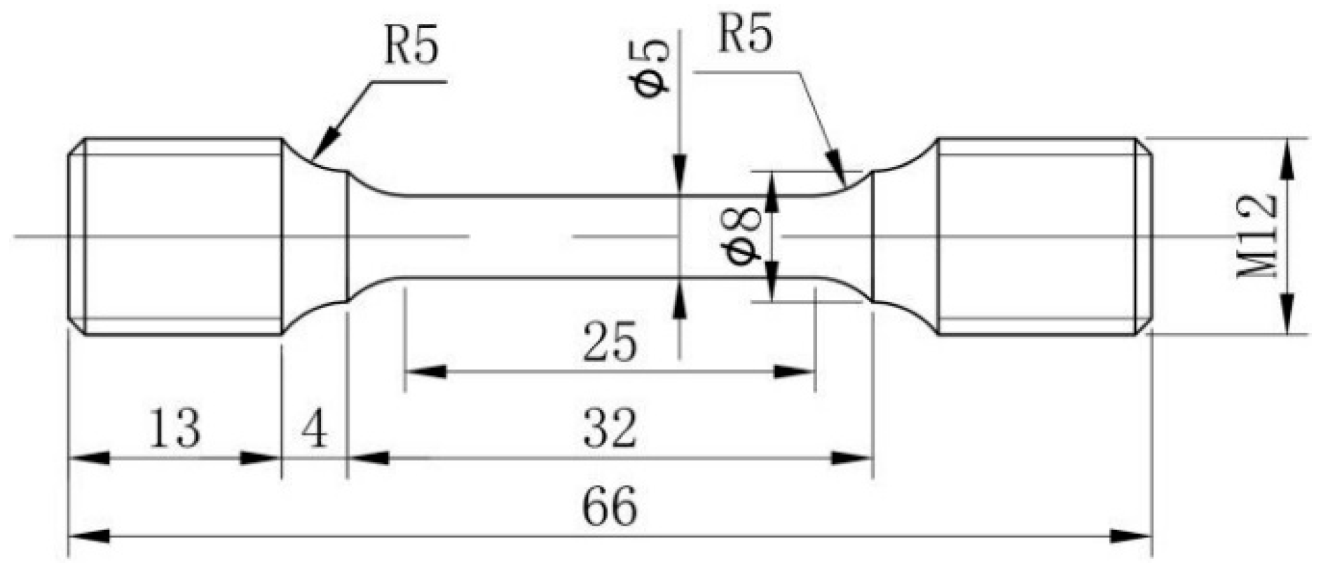
2. Materials and Methods

The composition of K439B alloy (wt.%) is 42.02% Cr + Co, 5.01% Al + Ti, 2.06% W, 0.85% Nb, 1.25% Ta, 0.11% C, with Ni balance [17]. The cylindrical bars used in this study were prepared by vacuum induction furnace, followed by remelting and casting. The pouring temperature and mold shell temperature were 1400 and 930 °C, respectively. The purity of the raw metals used for melting alloys was set to be higher than 99.95%. The as-cast specimens were subjected to a three-step standard heat treatment: solution treatment at 1160 °C for 4 h, first-stage aging at 1080 °C for 4 h, and second-stage aging at 845 °C for 16 h to obtain fine spherical γ′ precipitates. All of them were followed by air cooling. The specimens obtained after the above standard heat treatment processing will be hereafter referred to as alloys in the initial state. The initial state rods were then aged at 800 °C for 6000, 8000, and 10,000 h.
The specimens for stress rupture tests were machined from the long-term aged rods with a diameter of 5 mm and a gauge length of 25 mm. The load control accuracy of the test equipment is within 1%. The temperature controlling errors of the furnaces are in ±3 °C range. Before the formal test, a load of 400 N was applied to the sample and kept at the target temperature for 1 h to ensure the uniform temperature inside the sample. The thermocouple was bound to the center of the sample by high-temperature insulation rope. Stress rupture tests were performed on an RDL30 electronic creep machine (Sinotest Equipment Co., Ltd. Changchun, China) under 815 °C/379 MPa conditions. The technical drawing of the stress rupture specimen is shown in Figure 1.
The microstructure of alloys after long-term aging, the longitudinal section, and fracture surface of stress-ruptured samples were characterized by ZEISS SUPRA55 field emission scanning electron microscope (SEM, Carl Zeiss AG, Oberkochen, German). The secondary phases and carbides were analyzed using Energy Dispersive X-ray Spectroscopy (EDX, Carl Zeiss AG, Oberkochen, German). The detailed dislocation configurations of the fractured specimens were examined by FEI Tecnai G2 F20 field emission transmission electron microscope (TEM, FEI, Hillsboro, OR, USA). The SEM samples were polished and etched by chemical etching and electrolytic etching. The former etchant was composed of 10 mL HNO3 + 20 mL HF + 30 mL C3H8O3, which was used to reveal the grain boundaries. The latter was composed of 10 mL HNO3 + 20 mL CH3COOH + 170 mL H2O, which was used to observe the morphology of the γ′ phase (HNO3, HF, C3H8O3, CH3COOH, Beijing Tong Guang Fine Chemicals Company, Sanhe, Hebei, China). TEM samples were prepared by the twin-jet thinning method, using a solution of 10 vol.% HClO4 and 90 vol.% C2H5OH under the conditions of −25 °C and 25 V. The variable γ′ was quantitatively characterized using the image analysis software Image-Pro Plus (Version 6.0.0.260). At least three representative images were used to achieve statistical results.

3. Results and Discussion

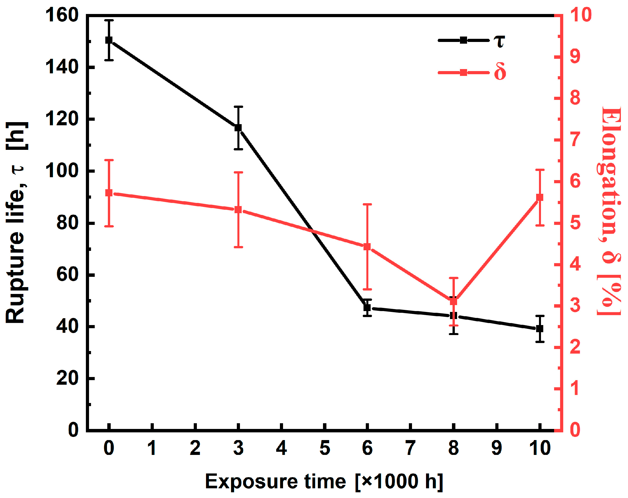
3.1. Stress Rupture Properties

The stress rupture life and elongation after fracture are shown in Figure 2. After aging the alloy for 6000 h, its stress rupture life diminished from an initial 150.4 ± 7.6 h [14] to 47.3 ± 3.1 h, representing a 68% reduction. As the aging time further extended to 10,000 h, the rupture life decreased to 39.1 ± 5.6 h, marking a more modest decline of 17%. This may be attributed to the decreased microstructure degradation rate after long-term aging up to 6000 h, and therefore a corresponding slowdown in the rate of stress rupture performance degradation. In addition, the fracture elongation of long-term aging alloys has little change compared to the standard heat-treated alloy, fluctuating between 3.1 and 5.7%. Upon enduring long-term thermal exposure at 800 °C for a period ranging from 6000 to 10,000 h, the K439B alloy exhibited a rather smooth trend of stress rupture life reduction compared to the aging period of 0 to 6000 h, indicating good stability of stress rupture performance in long-term thermal exposure.

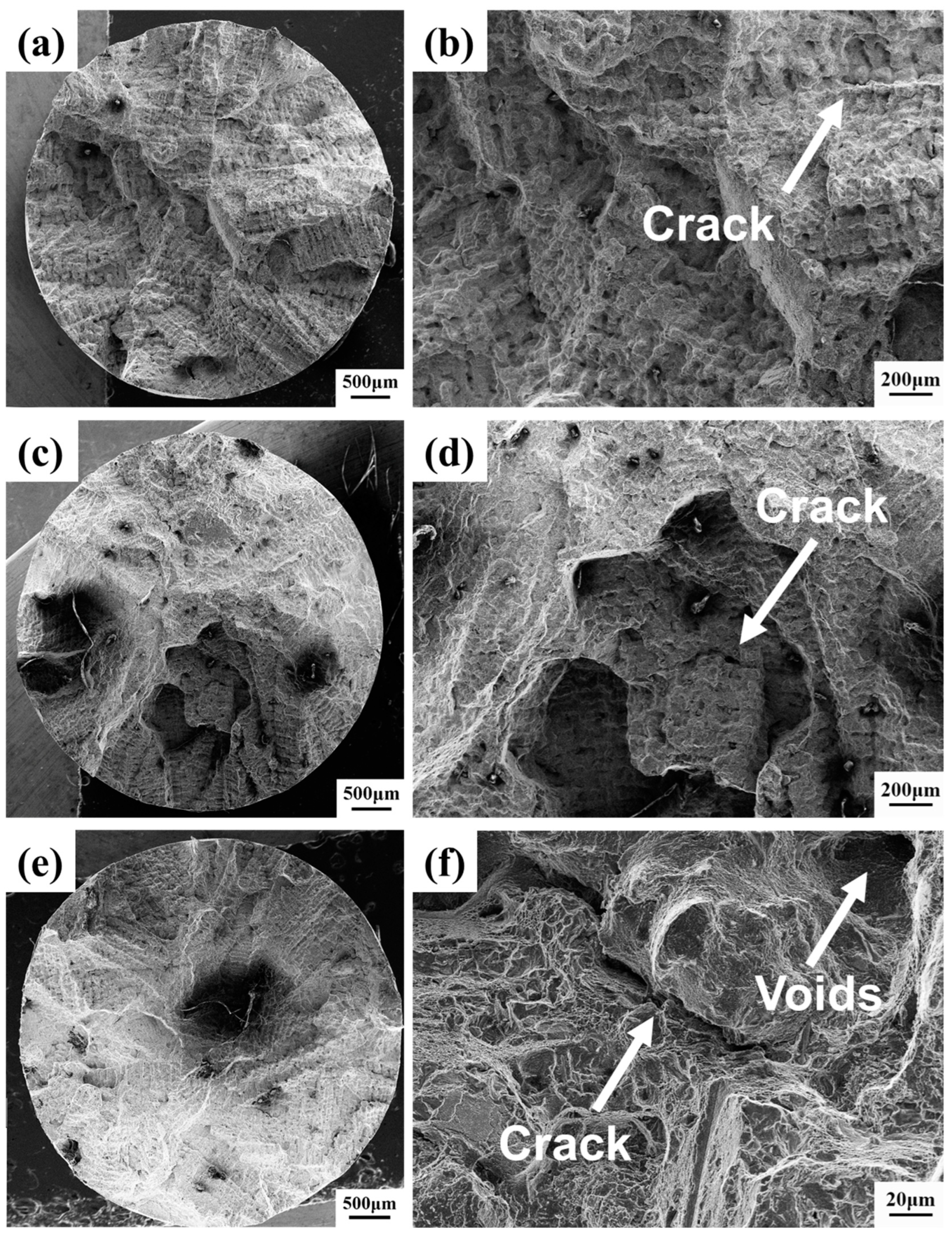
3.2. Fracture Morphology and Crack Features

The fracture morphology of K439B alloy under different long-term thermal exposure conditions, i.e., 6000, 8000, and 10,000 h, are presented in Figure 3. The aging time has a significant effect on the creep fracture morphology. The fracture surfaces of all samples exhibited a quasi-circular configuration, orthogonal to the applied stress direction, exhibiting a mixed fracture mode of intergranular and transgranular fracture. After aging for 6000 h, the fracture modes show both brittle interdendritic and intergranular characteristics. In the magnified picture shown in Figure 3b,d,f, visible voids and cracks were discernible within the samples. Figure 3d,f illustrates clearly the site of crack initiation. The formation of creep voids and the subsequent cracking during creep testing can be attributed to the failure of the samples. In addition, the brittle quasi-cleavage morphology was observed, and the step of the cleavage appeared. Especially, voids emerged as the dominant features at crack initiation sites after thermal aging for 8000 h, underscoring their crucial contribution to the fracture mechanism [18]. As the aging time prolongs, the fracture surface contains more dimples and less quasi-cleavage than the 8000 h-sample, which is characterized by ductile fracture.
To further investigate the path of crack propagation, microstructure in the longitudinal section of the stress ruptured samples near the fracture surface are presented in Figure 4. Obvious intergranular cracks can be observed after thermal exposure for 6000–10,000 h. Intergranular cracks propagate from the fracture to the interiors of the samples and mainly occur at the interface between grain boundary carbides and the grain matrix. The decohesion at the interface between the carbides and the matrix results from a loss of strength [19]. In addition, it was also observed that microcracks propagated at carbides-free boundaries, as shown in Figure 4b–d. For carbides-free grain boundaries, large orientation differences between different grains can also cause a large accumulation of dislocations, leading to large stress concentration and cracking.

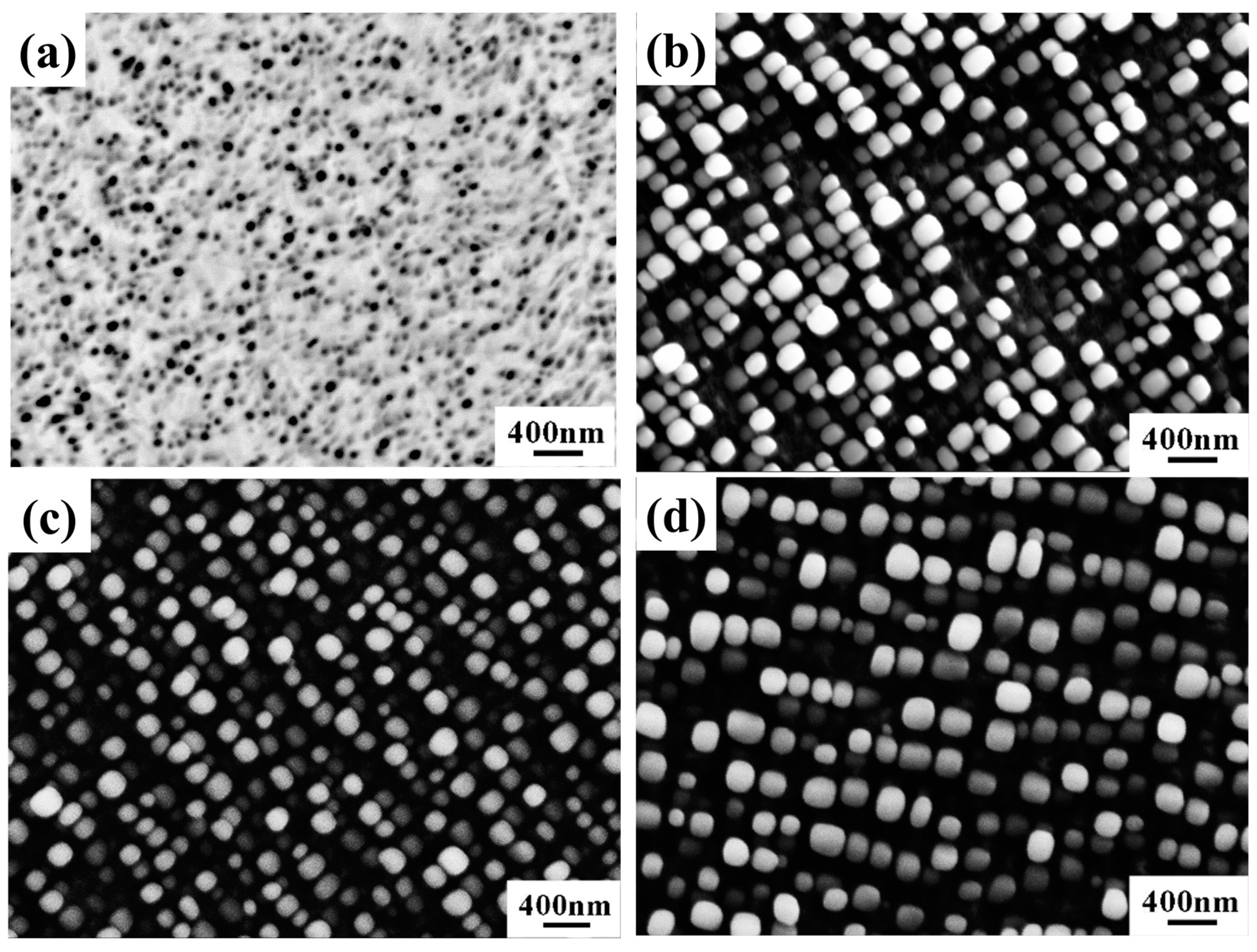
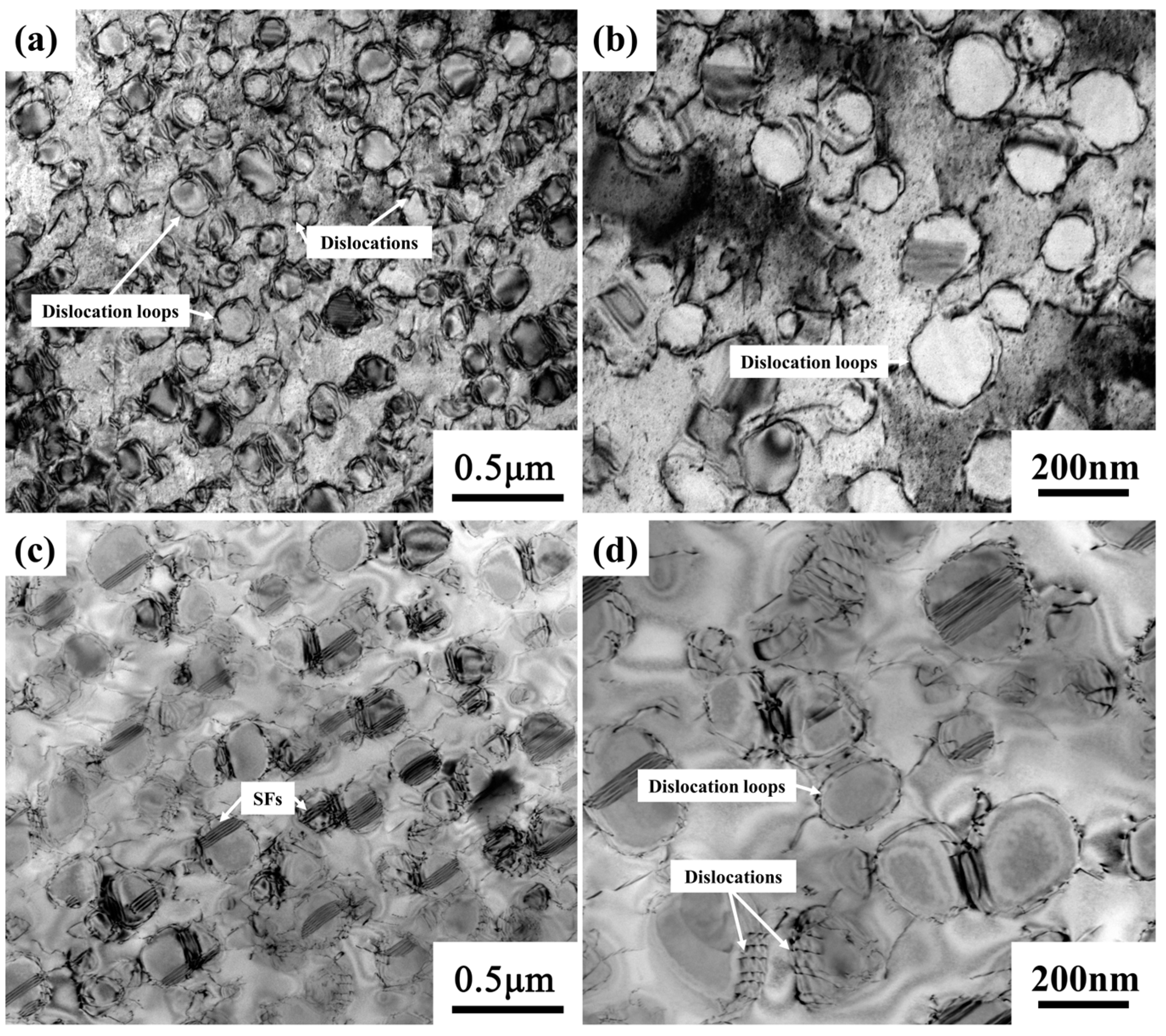
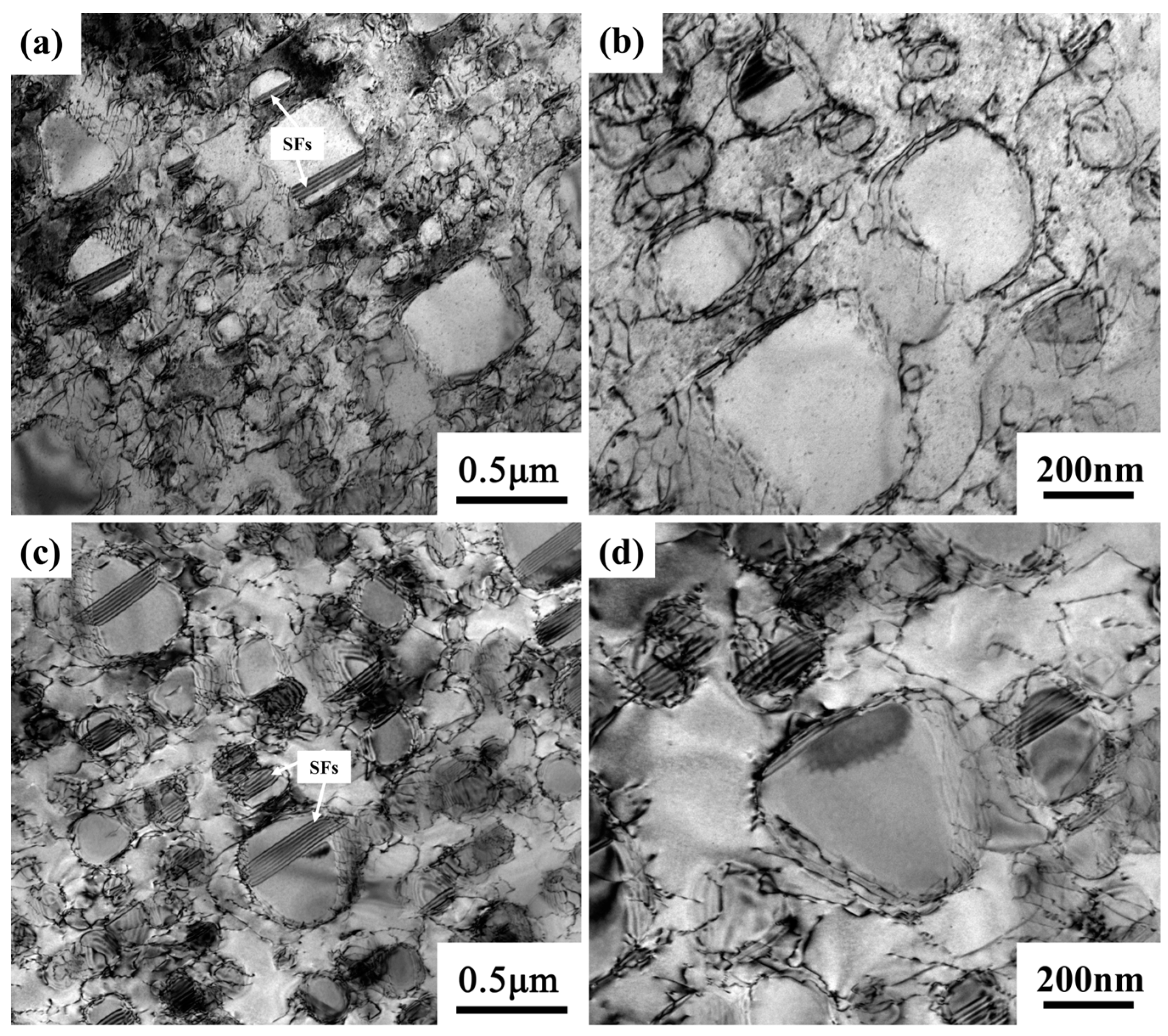
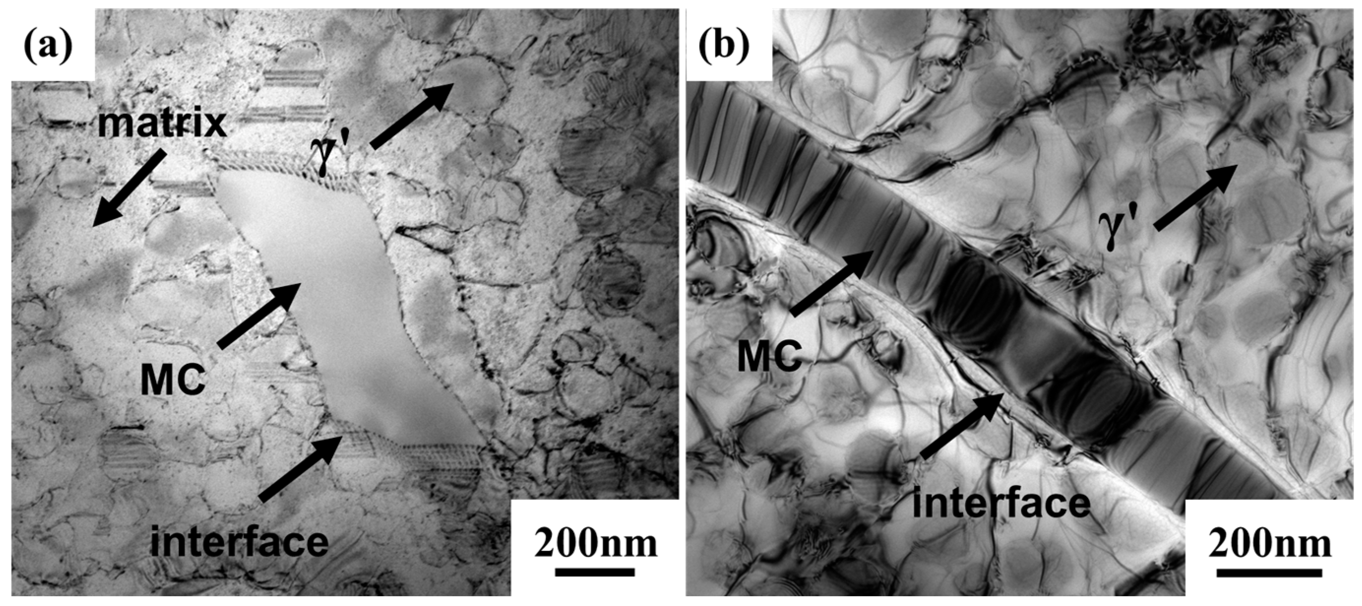
3.3. Analysis of Stress Rupture Degradation and Deformation Mechanisms

The γ′ phase morphology subject to long-term aging is shown in Figure 5. The spherical γ′ phase with an average size of 45 nm formed after standard heat treatment. The γ′ phase exhibits a rounded cubic shape after 800 °C thermal exposure. The size of the γ′ phase gradually increased and the average diameter of the γ′ phase reached about 137 nm and 164 nm after aging for 6000 h and 10,000 h, respectively. Considering that the average diameter of the γ′ phase after aging for 3000 h has reached 120.3 nm [14], the K439B superalloy exhibits a rather slow γ′ phase degradation rate during 800 °C thermal exposure. The volume fraction of the γ′ phase was higher than standard heat treatment specimens and only slightly increased during aging from 6000 h to 10,000 h, because the increase in volume fraction of γ′ mainly came from the coarsening of the γ′ phase after it coarsened to a certain extent. Aghaie-Khafri proposed that the ln ( t r ) is proportional to ln ( d / λ 2 ) , where tr is the rupture life, λ and d are the mean planar interparticle distance and γ′ diameter, respectively [20]. Hence, the rupture life degradation of the alloy during thermal exposure is mainly affected by the size of γ′ precipitates, which is in accordance with our results.
The morphology, size, volume fraction, and distribution of the γ′ phase significantly influence the stress rupture properties of superalloys [21]. The interaction between γ′ and dislocation configuration after long-term aging for 6000 h is shown in Figure 6. The Orowan looping process was observed and left the loops around the γ′ phases, as shown in Figure 6a,b. The γ′ precipitates serve as potent impediments, effectively inhibiting the mobility of dislocations [22]. The process of γ′ phase coarsening leads to an increase in the mean inter-particle spacing of γ′ precipitates, subsequently resulting in a reduction in the Orowan bowing stress. This decrease facilitates the homogenization of dislocation glide mechanisms, constituting an efficacious approach to enhancing creep resistance and, consequently, prolonging the stress-rupture life. In Figure 6c,d, the isolated stack faults (SFs) within the γ′ particles further validate the dislocation shearing mechanism during the creep process. The SFs exclusively present within γ′ precipitates lack the capability to interact with the mobile dislocations located in the matrix [23,24]. Rather, shearing confined within the γ′ phase alone has the potential to mitigate strain hardening in the matrix, thereby promoting enhanced dislocation mobility. As a result, the emergence of such SFs facilitates an accelerated progression towards stress rupture.
After aging for 10,000 h, the dislocation configurations were similar to those of the samples aged for 6000 h, which were still dominated by the dislocation shearing mechanism, as shown in Figure 7. Specifically, more isolated SFs cut through the γ′ phase while the number of dislocation loops decreased. It is reasonable to speculate that, with the increase in long-term aging time, the SFs shearing mechanism gradually dominated creep deformation.
The MC carbides represent quintessential strengthening phases within superalloys, as documented in references [25,26]. However, during high-temperature creep deformation, the decomposition of these carbides can manifest, a phenomenon that is commonly regarded as adverse to the superior temperature capabilities of superalloys, as outlined in reference [27]. Plastic deformation of MC carbides during high-temperature creep has been confirmed, with this observation being corroborated by the presence of high-density dislocations within the MC carbides and the formation of steps at the matrix/MC interfaces (Figure 8). As high-density dislocations accumulate within the MC carbides, the interface between the MC phase and the matrix progressively acquires a wavy configuration, as depicted in Figure 8b. This morphological transformation may serve to alleviate stress concentrations at the matrix/MC interfaces, ultimately enhancing the creep resistance of the material. However, high-density dislocations accelerate the diffusion of Cr, Co, and Ni into MC carbides, resulting in the elemental inhomogeneous distribution. A high density of M23C6 carbides forms in the MC interior. As partially coherent interfaces formed between M23C6 and MC carbides, where stress concentration and associated debonding are more likely to occur, the decomposition behavior is likely responsible for the fracture of MC carbides. This is consistent with that shown in Figure 4, where the MC carbides were partially fractured after the creep test.

4. Conclusions

In this work, long-term thermal exposure at 800 °C for 6000, 8000, and 10,000 h was conducted for the K439B superalloy, and the evolution of stress rupture properties at 815 °C/379 MPa, fracture morphology, and deformation mechanism were investigated. The main conclusions can be drawn as follow:
(1) After long-term thermal exposure at 800 °C for 10,000 h, the stress rupture life of K439B alloy was reduced by nearly ~100 h compared to the standard heat-treated state, ranging from 150.4 ± 7.6 to 39.1 ± 5.6 h. Yet, during the long-term thermal exposure of 6000–10,000 h, the decrease in stress rupture life was not significant, ranging from 47.3 ± 3.1 to 39.1 ± 5.6 h.
(2) The fracture surface of the stress-ruptured samples exhibited a mixed fracture mode of intergranular and ductile transgranular fractures. During the stress rupture process, several creep pores are first formed at the grain boundaries, and then gradually connected into intergranular microcracks. The microcracks further propagate along the grain boundaries, ultimately becoming the main cause of creep-induced damage. Both the surface and interior of the sample are prone to the initiation of intergranular microcracks.
(3) There are mainly two dislocation configurations in the thermally exposed samples stress-ruptured at 815 °C/379 MPa, namely, dislocation bypassing and isolated stacking fault shearing of the γ′ phase. For the alloys thermally exposed for 6000 h, the predominant creep deformation mechanism is Orowan bypassing of dislocations, and more stacking faults are formed in the γ′ phases. With increasing thermal exposure time, the γ′ phase size increases, and more parallel stacking faults appear in the γ′ phases. The Orowan bypass mechanism is gradually replaced by the stacking faults shearing mechanism, resulting in a corresponding decrease in stress rupture life.

Author Contributions

Conceptualization, Y.W., J.C. and X.H.; methodology, Y.W., X.Q., Z.D. and L.G.; validation, Y.W. and C.S.; formal analysis, Z.D. and L.G.; investigation, X.Q., C.S. and L.G.; resources, X.H.; data curation, Y.W., X.Q. and L.G.; writing—original draft preparation, Y.W., X.Q. and L.G.; writing—review and editing, Y.W. and L.G.; visualization, Y.W., X.Q. and L.G.; supervision, X.H.; project administration, X.H.; funding acquisition, J.C. and X.H. All authors have read and agreed to the published version of the manuscript.

Funding

This work was supported by the National Science and Technology Major Project of China (No. J2019-VI-0004-0117), Self-innovation Special Fund Project of Aero Engine Corporation of China (ZZCX-2022-040), and Science and Technology on Advanced High Temperature Structural Materials Laboratory Fund (No. 6142903220101).

Data Availability Statement

The original contributions presented in this study are included in the article. Further inquiries can be directed to the corresponding authors.

Conflicts of Interest

Author Jingyang Chen was employed by AECC Beijing Institute of Aeronautical Materials. The remaining authors declare that the research was conducted in the absence of any commercial or financial relationships that could be construed as a potential conflict of interest.

References

  1. Du, B.; Hu, Z.; Sheng, L.; Cui, C.; Yang, J.; Zheng, Y.; Sun, X. Tensile, creep behavior and microstructure evolution of an as-cast Ni-based K417G polycrystalline superalloy. J. Mater. Sci. Technol. 2018, 34, 1805–1816. [Google Scholar] [CrossRef]
  2. Li, D.; Cai, W.; Liu, Z.; Shen, X.; Wang, H.; Zhu, G.; Shu, D. Elemental mapping and quantitative characterization of dendrite structure in IN718 supperalloy based on micro beam X-ray fluorescence and EPMA. Vacuum 2022, 198, 110859. [Google Scholar] [CrossRef]
  3. Ye, R.; Li, H.; Ding, R.; Doel, T.J.A.; Bray, S.; Walpole, A.; Bowen, P. Microstructure and microhardness of dissimilar weldment of Ni-based superalloys IN718-IN713LC. Mater. Sci. Eng. A 2020, 774, 138894. [Google Scholar] [CrossRef]
  4. Mostafaei, A.; Ghiaasiaan, R.; Ho, I.T.; Strayer, S.; Chang, K.; Shamsaei, N.; Shao, S.; Paul, S.; Yeh, A.; Tin, S.; et al. Additive manufacturing of nickel-based superalloys: A state-of-the-art review on process-structure-defect-property relationship. Prog. Mater. Sci. 2023, 136, 101108. [Google Scholar] [CrossRef]
  5. Wang, Z.; Guan, K.; Gao, M.; Li, X.; Chen, X.; Zeng, X. The microstructure and mechanical properties of deposited-IN718 by selective laser melting. J. Alloys Compd. 2012, 513, 518–523. [Google Scholar] [CrossRef]
  6. Zhao, Y.; Guo, Q.; Ma, Z.; Yu, L. Comparative study on the microstructure evolution of selective laser melted and wrought IN718 superalloy during subsequent heat treatment process and its effect on mechanical properties. Mater. Sci. Eng. A 2020, 791, 139735. [Google Scholar] [CrossRef]
  7. Chen, J.; Ren, X.; Zhang, M.; Zhang, L.; Tang, X.; Xiao, C. Microstructure and typical properties of cast Ni-based superalloy K439B. Heat Treat. Met. 2023, 48, 100–104. [Google Scholar]
  8. Guo, X.; Zheng, W.; An, W.; Antonov, S.; Li, L.; Cormier, J.; Feng, Q. High temperature creep behavior of a cast polycrystalline nickel-based superalloy K465 under thermal cycling conditions. Materialia 2020, 14, 100913. [Google Scholar] [CrossRef]
  9. Kang, M.; Sridar, S.; Xiong, W.; Wang, J.; Yu, J.; Sun, B. Influence of long-term aging on microstructural stability and performance of DD6 superalloy. Mater. Sci. Technol. 2021, 37, 607–615. [Google Scholar] [CrossRef]
  10. Zhang, P.; Yuan, Y.; Yan, J.; Wang, J.; Song, X.; Yang, G. Morphological evolution of γ′ precipitates in superalloy M4706 during thermal aging. Mater. Lett. 2018, 211, 107–109. [Google Scholar] [CrossRef]
  11. Ou, M.; Ma, Y.; Hou, K.; Wang, M.; Ma, G.; Liu, K. Effect of grain boundary precipitates on the stress rupture properties of K4750 alloy after long-term aging at 750°C for 8000 h. J. Mater. Sci. Technol. 2021, 92, 11–20. [Google Scholar] [CrossRef]
  12. Cui, J.; Zhang, J.; Yao, J. Effect of Thermal Exposure on the Microstructure and Stress-Rupture Properties of a Directionally Solidified Superalloy. J. Mater. Eng. Perform. 2021, 30, 9200–9208. [Google Scholar] [CrossRef]
  13. Chen, J.; Huo, Q.; Chen, J.; Wu, Y.; Li, Q.; Xiao, C.; Hui, X. Tailoring the creep properties of second-generation Ni-based single crystal superalloys by composition optimization of Mo, W and Ti. Mater. Sci. Eng. A 2021, 799, 140163. [Google Scholar] [CrossRef]
  14. Zhang, L.; Chen, J.; Tang, X.; Xiao, C.; Zhang, M.; Yang, Q. Evolution of microstructures and mechanical properties of K439B superalloy during long-term aging at 800 °C. Acta Metall. Sin. 2023, 59, 1253–1264. [Google Scholar]
  15. Jahangiri, M.R.; Abedini, M. Effect of long time service exposure on microstructure and mechanical properties of gas turbine vanes made of IN939 alloy. Mater. Des. 2014, 64, 588–600. [Google Scholar] [CrossRef]
  16. Gao, L.; Qu, X.; Wu, Y.; Chen, J.; Xiao, C.; Hui, X. Evolution of carbides in K439B nickel-based cast superalloy during long-term aging at 800 °C. Mater. Rep. 2024, 38, 12–16. [Google Scholar]
  17. Liu, Z.; Li, C.; Dong, A.; Gu, J. Effect of initial microstructure on the properties of K439B nickel-based superalloy during prolonged aging at 800 °C. Intermetallics 2024, 172, 108364. [Google Scholar] [CrossRef]
  18. Azadi, M.; Marbout, A.; Safarloo, S.; Azadi, M.; Shariat, M.; Rizi, M.H. Effects of solutioning and ageing treatments on properties of Inconel-713C nickel-based superalloy under creep loading. Mater. Sci. Eng. A 2018, 711, 195–204. [Google Scholar] [CrossRef]
  19. Kvapilova, M.; Kral, P.; Dvorak, J.; Hutar, P.; Sklenicka, V. Evolution of high-temperature creep behaviour in cast GTD-111 nickel-based superalloy. Procedia Struct. Integr. 2024, 52, 89–98. [Google Scholar] [CrossRef]
  20. Aghaie-Khafri, M.; Hajjavady, M. The effect of thermal exposure on the properties of a Ni-base superalloy. Mater. Sci. Eng. A 2008, 487, 388–393. [Google Scholar] [CrossRef]
  21. Shi, Z.; Li, J.; Liu, S. Effect of long term aging on microstructure and stress rupture properties of a nickel based single crystal superalloy. Prog. Nat. Sci. Mater. Int. 2012, 22, 426–432. [Google Scholar] [CrossRef]
  22. Sun, F.; Gu, Y.; Yan, J.; Zhong, Z.; Yuyama, M. Phenomenological and microstructural analysis of intermediate temperatures creep in a Ni–Fe-based alloy for advanced ultra-supercritical fossil power plants. Acta Mater. 2016, 102, 70–78. [Google Scholar] [CrossRef]
  23. Lu, S.; Antonov, S.; Li, L.; Feng, Q. Two Steady-State Creep Stages in Co-Al-W-Base Single-Crystal Superalloys at 1273K/137 MPa. Metall. Mater. Trans. A 2018, 49, 4079–4089. [Google Scholar] [CrossRef]
  24. Rae, C.M.F.; Matan, N.; Reed, R.C. The role of stacking fault shear in the primary creep of [001]-oriented single crystal superalloys at 750°C and 750 MPa. Mater. Sci. Eng. A 2001, 300, 125–134. [Google Scholar] [CrossRef]
  25. Hu, X.; Qin, X.; Hou, J.; Zhou, L.; Ma, X. Microstructural characterization of the M23C6 carbide in a long-term aged Ni-based superalloy. Philos. Mag. Lett. 2017, 97, 43–49. [Google Scholar] [CrossRef]
  26. Lvov, G.; Levit, V.I.; Kaufman, M.J. Mechanism of primary MC carbide decomposition in Ni-base superalloys. Metall. Mater. Trans. A 2004, 35, 1669–1679. [Google Scholar] [CrossRef]
  27. Ge, H.; Liu, G.; Zheng, S.; Yang, Y.; Liu, K.; Ma, X. Dislocation climbing dominated decomposition and fracture of carbides in a Ni-based superalloy. Acta Mater. 2023, 246, 118669. [Google Scholar] [CrossRef]
Figure 1. The technical drawing of the specimen for stress rupture test (unit: mm).
Metals 14 01461 g001
Figure 2. Evolution of stress rupture life and fracture elongation at 815 °C/379 MPa for the K439B alloy thermally exposed at 800 °C. The data of the sample aged for 0 and 3000 h were adapted from Ref. [14].
Metals 14 01461 g002
Figure 3. The fracture morphology of the ruptured K439B specimen under 815 °C/379 MPa, which are thermally exposed for (a,b) 6000 h, (c,d) 8000 h, and (e,f) 10,000 h.
Metals 14 01461 g003
Figure 4. The fractography of samples after stress ruptured at 815 °C/379 MPa, which were thermally exposed for different times. (a) Secondary electron SEM image for the sample aged for 6000 h; and backscattered electron SEM image of the samples aged for (b) 6000 h, (c) 8000 h, and (d) 10,000 h. (The photos in the red and yellow boxes in the figure are partial enlargements of the corresponding small boxes. The direction of σ indicates the direction of the applied stress.).
Metals 14 01461 g004
Figure 5. SEM micrographs showing the morphology of the γ′ phase in K439B alloy after long-term aging: (a) 0 h; (b) 6000 h; (c) 8000 h; (d) 10,000 h.
Metals 14 01461 g005
Figure 6. TEM bright field images of the dendrite core (a,b) and interdendritic regions (c,d) near the fracture of the ruptured specimen under 815 °C/379 MPa, which are thermally exposed for 6000 h.
Metals 14 01461 g006
Figure 7. TEM bright field images of the dendrite core (a,b) and interdendritic regions (c,d) near the fracture of the ruptured specimen under 815 °C/379 MPa, which are thermally exposed for 10,000 h.
Metals 14 01461 g007
Figure 8. TEM images of the carbides near the fracture of ruptured specimen under 815 °C/379 MPa, which are thermally exposed for different times: (a) dislocations within MC carbides after 6000 h; (b) wavy-like dislocation configuration after 10,000 h.
Metals 14 01461 g008
Disclaimer/Publisher’s Note: The statements, opinions and data contained in all publications are solely those of the individual author(s) and contributor(s) and not of MDPI and/or the editor(s). MDPI and/or the editor(s) disclaim responsibility for any injury to people or property resulting from any ideas, methods, instructions or products referred to in the content.

