
High-Cycle Fatigue Characteristics of Aluminum/Steel Clinched and Resistance-Spot-Welded Joints Based on Failure Modes


Abstract
1. Introduction
2. Materials and Methods
2.1. Investigated Materials
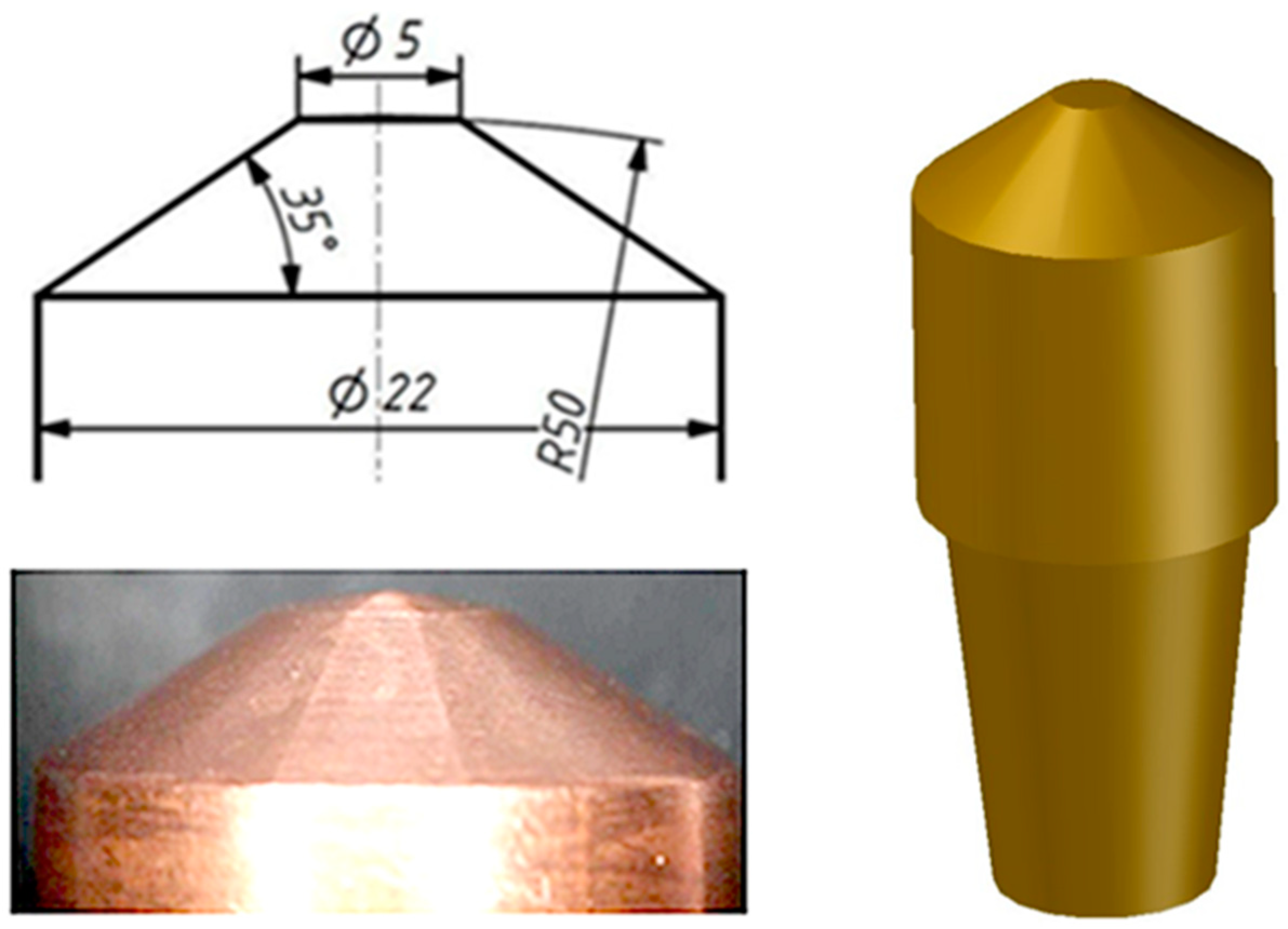
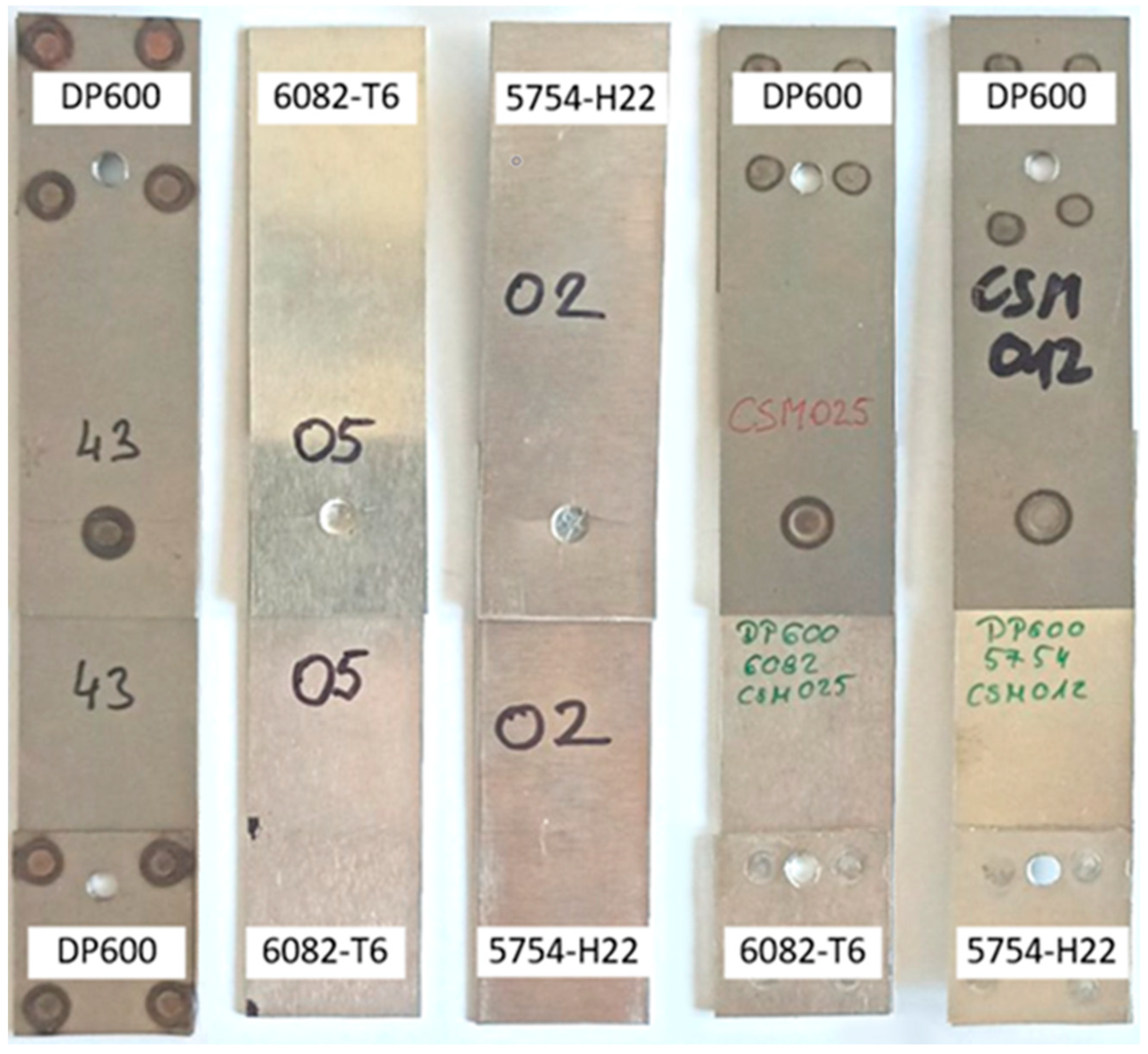
2.2. Resistance Spot Welding (RSW)
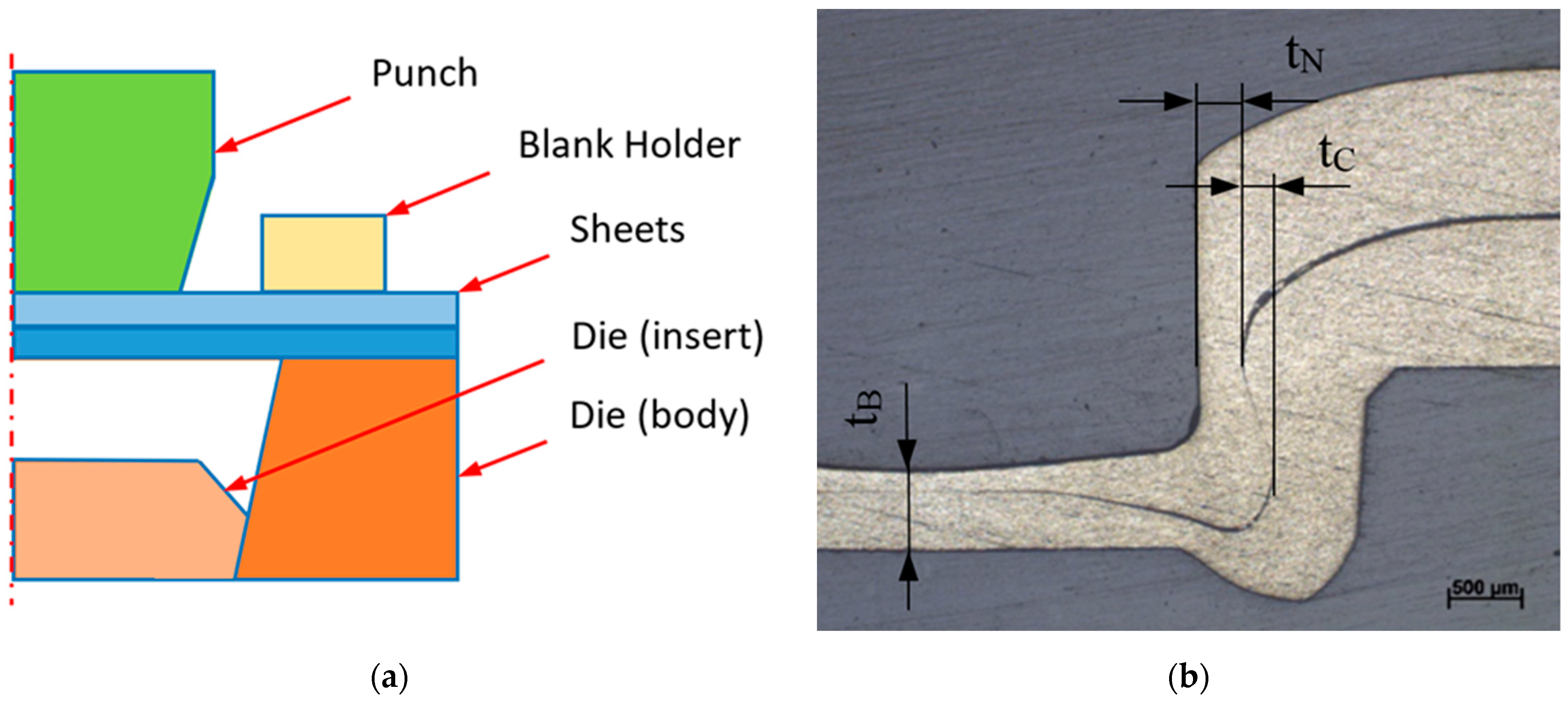
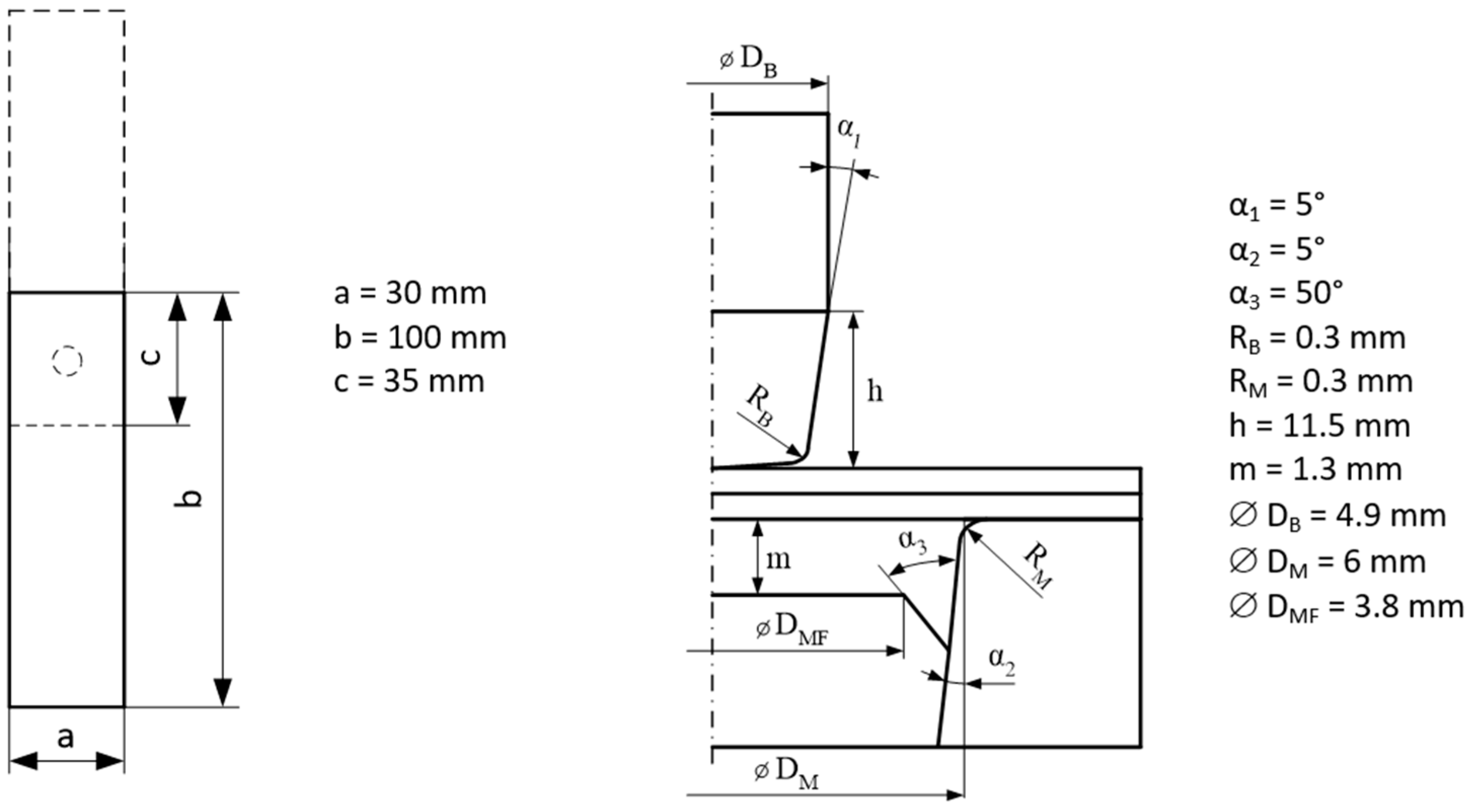
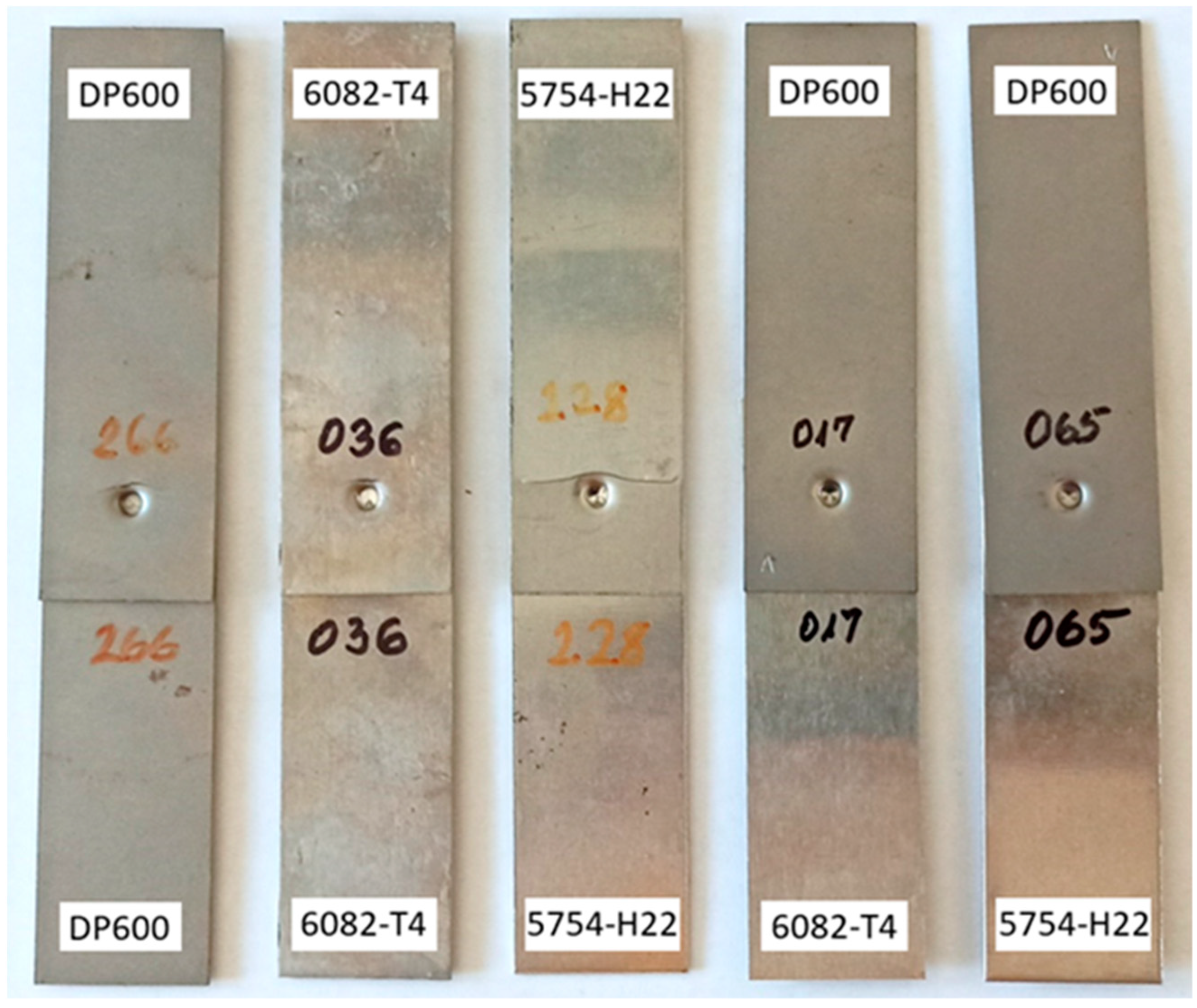
2.3. Conventional Clinching (CCL)
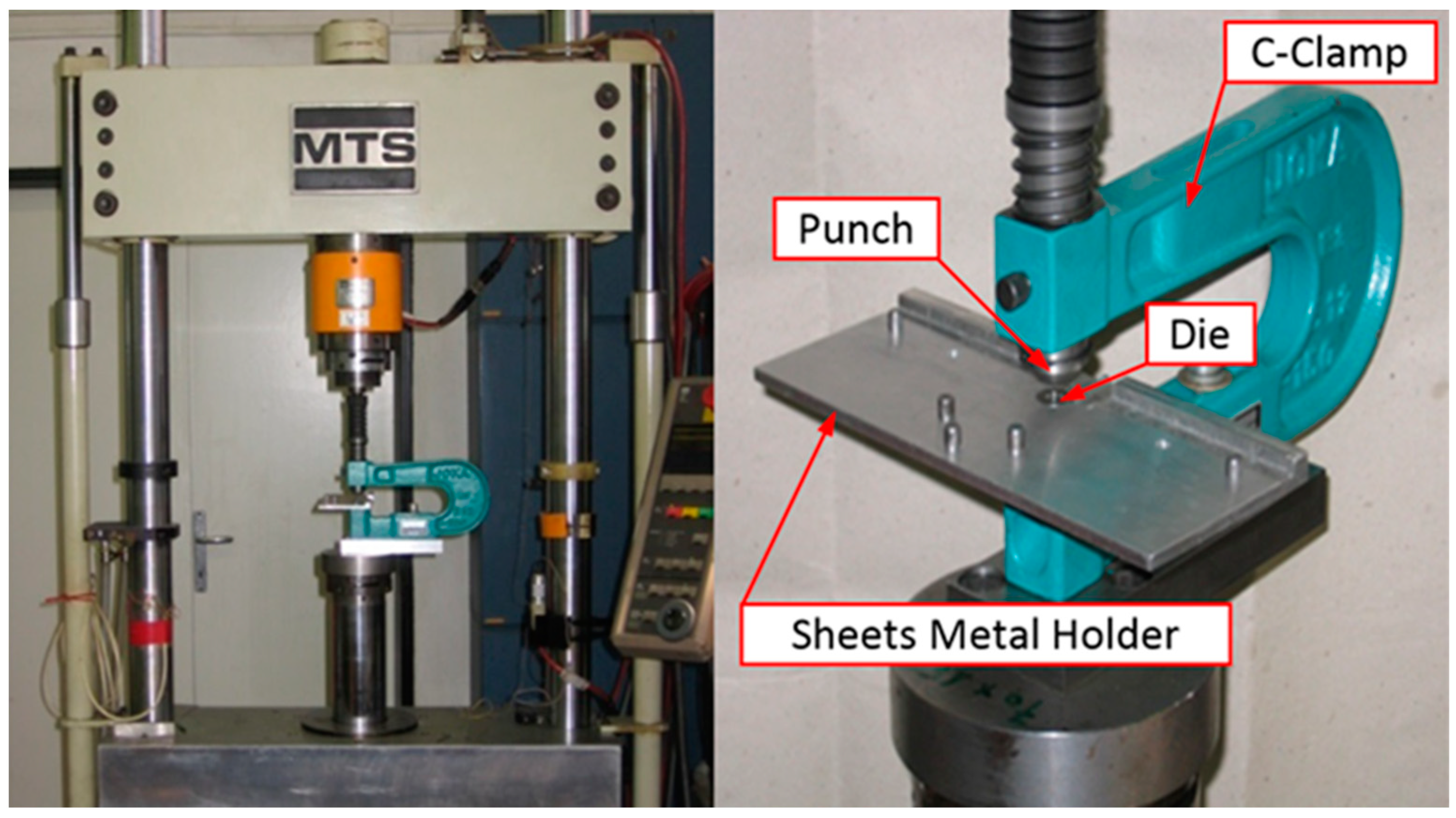
2.4. High-Cycle Fatigue (HCF) Tests
3. Results and Discussion
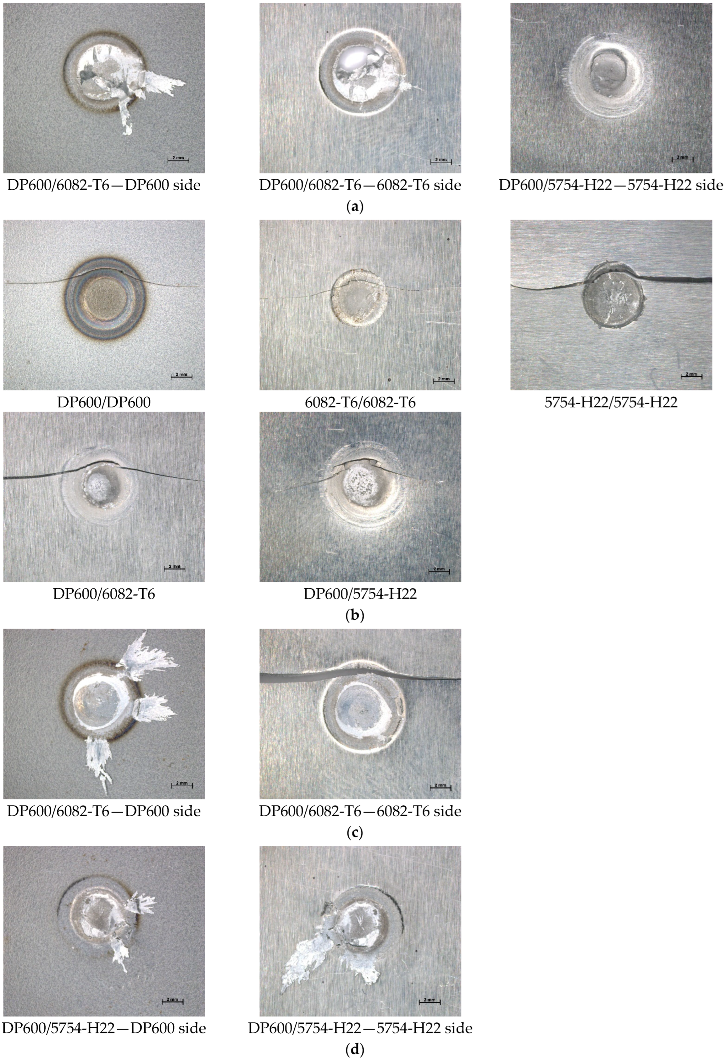
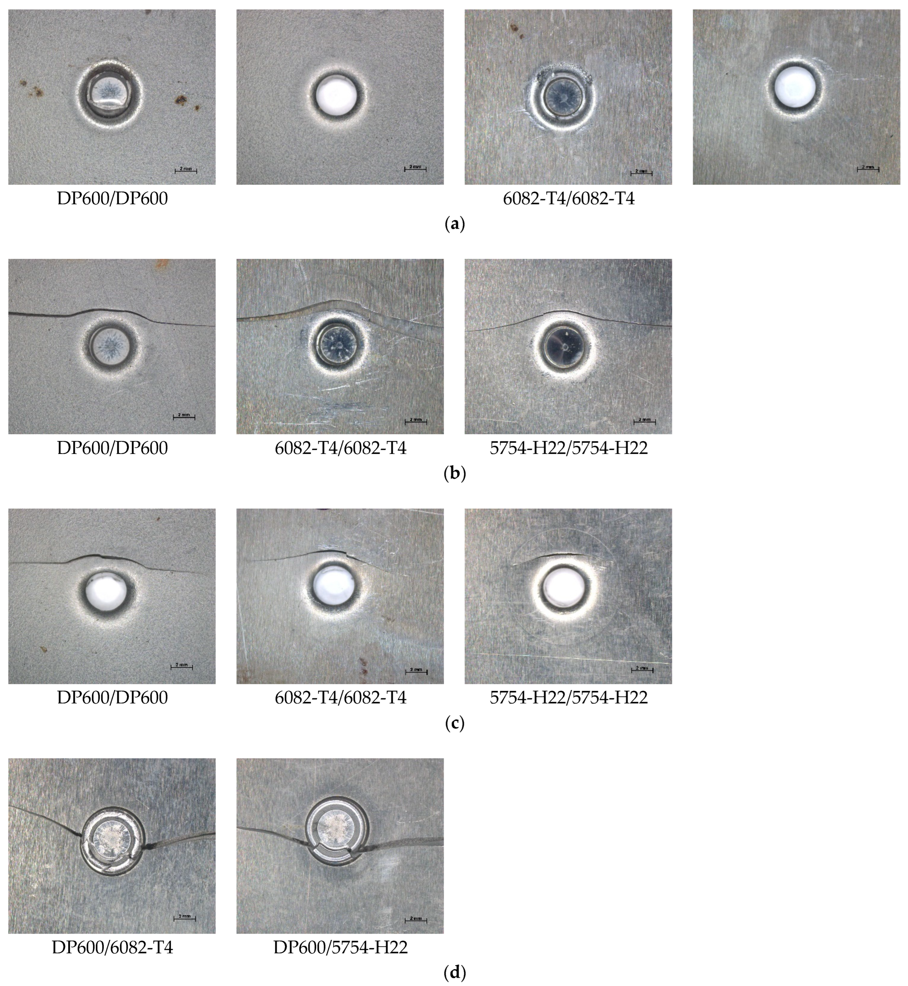
3.1. Failure Modes
3.2. Results of the High-Cycle Fatigue (HCF) Tests
3.3. Cost Comparison
4. Conclusions
- The investigated joining technologies issued comparable high-cycle fatigue (HCF) test results for the similar and hybrid resistance-spot-welded (RSW) and conventionally clinched (CCL) joints made from DP600, 5754-H22, and 6082-T6 base materials, both within and between the two technologies.
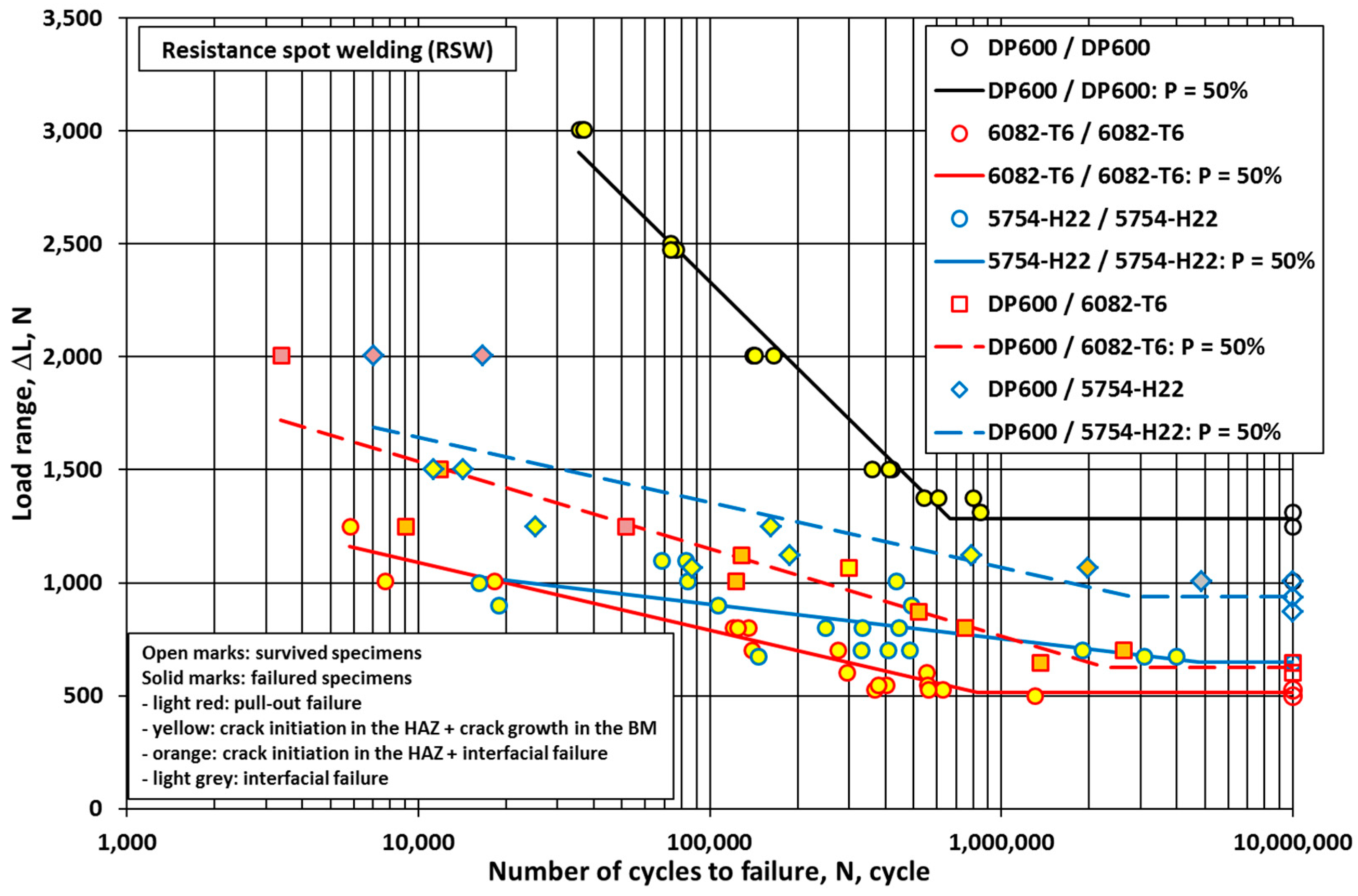
- For both the joining technologies used, the typical failure modes could be identified in the high-cycle fatigue investigations. In the case of RSW, the most common failure modes across the entire range were “crack initiation in the HAZ and crack growth in the base material” and “crack initiation in the HAZ and interfacial failure”; furthermore, the mode “pull-out failure” occurred at higher loads and lower cycles, and the mode “interfacial failure” occurred at lower loads and higher cycles. In the case of CCL, different failure modes occurred for the similar DP600/DP600 and the dissimilar joints, with the typical modes “base material fracture” and “button neck fracture” occurring at higher loads and lower cycles, and the mode “base material fracture and button neck fracture” occurring at lower loads and higher cycles. For the dissimilar joints, all specimens failed in the mode “initiation in the joint and crack growth in the aluminum alloy”.
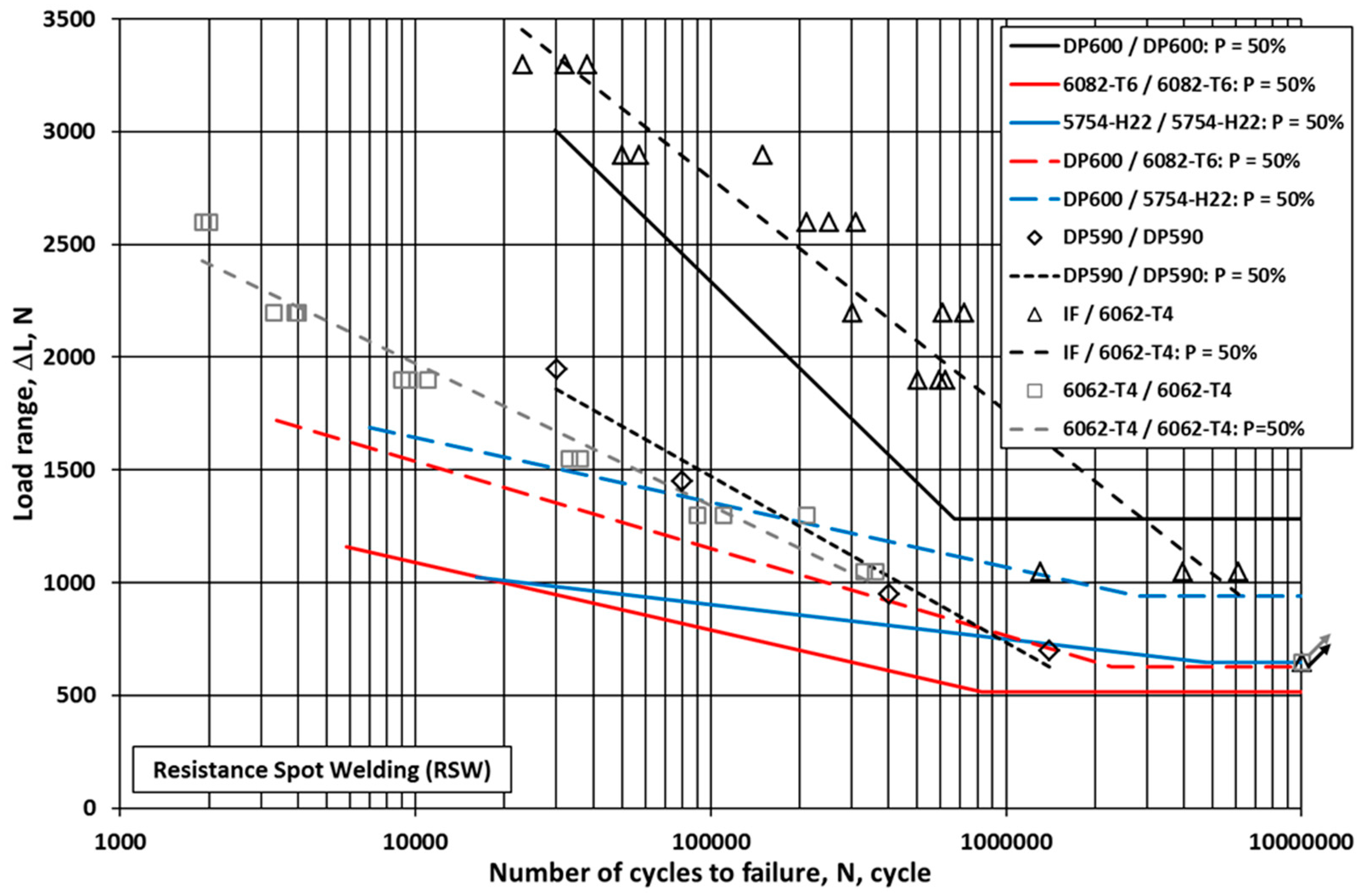
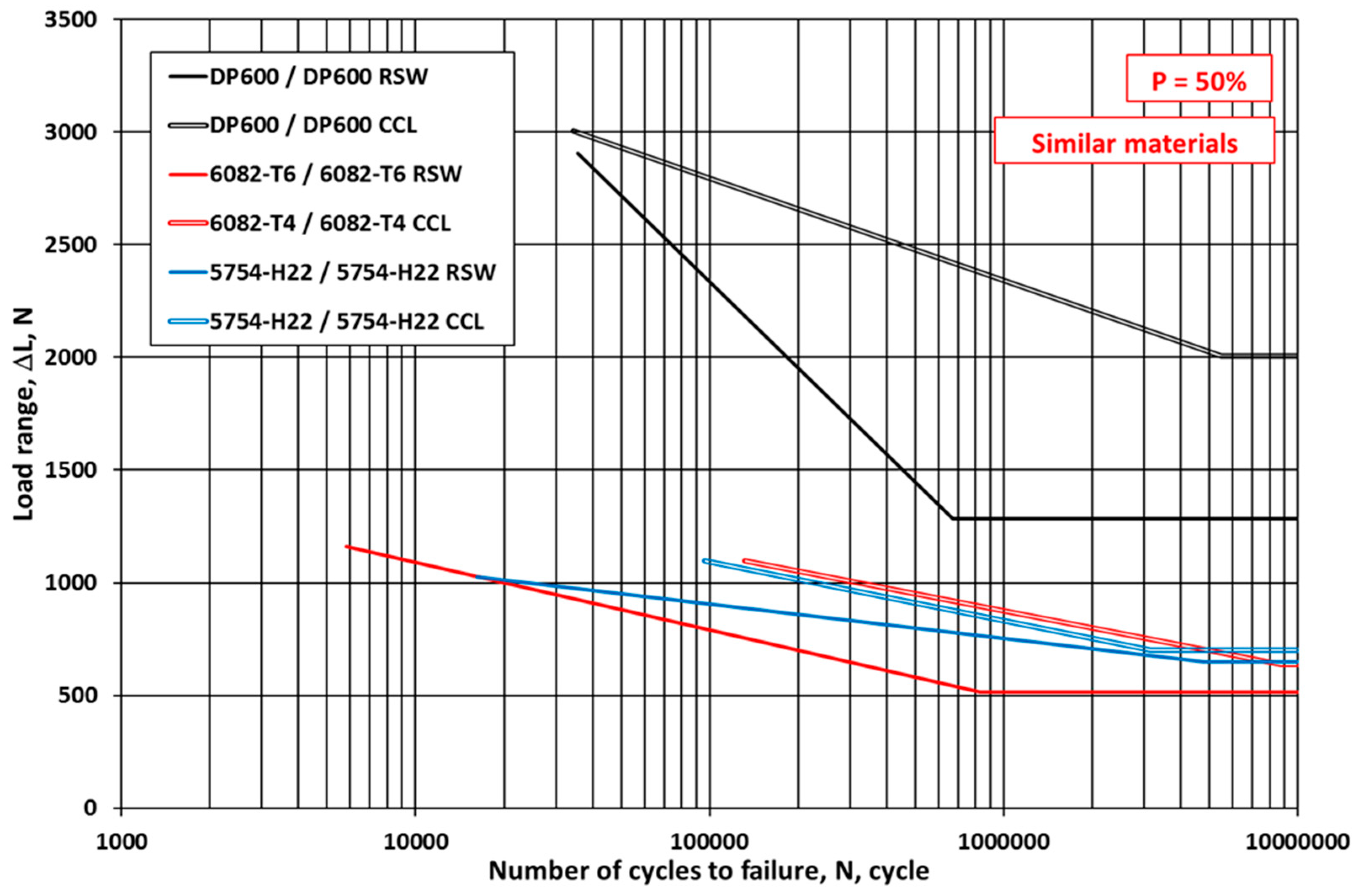
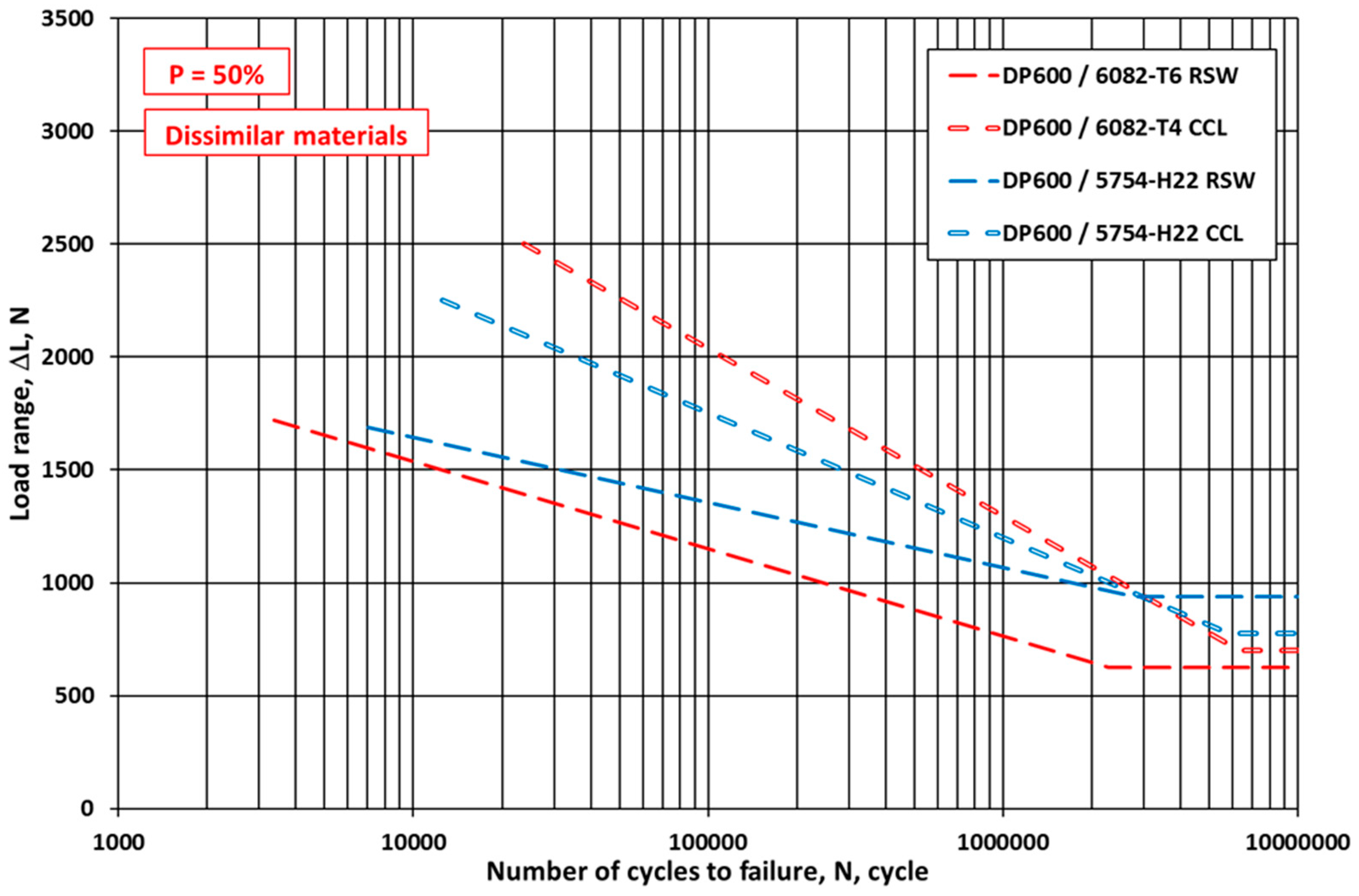
- Based on a Basquin-type equation, applying the least squares method in the lifetime stage and further calculating the mean values in the endurance limit stage, high-cycle fatigue limit curves (ΔL-N) can be determined corresponding to a 50% probability of failure. In the case of both the similar and the hybrid joints, the fatigue limit curves demonstrated that the load-bearing capacity of the CCL joints exceeds that of the RSW joints. Compared to the steel/steel joints, the load-bearing capacity of the hybrid joints is lower (48.7% and 73.0% for RSW, 35.0% and 38.7% for CCL), and it is even lower for the aluminum/aluminum joints (39.9% and 50.4% for RSW, 31.7% and 35.0% for CCL). The load-bearing capacity of the CCL joints is higher than that of the RSW joints (DP600/DP600: 156.1%, 6082-T4/6082-T4: 124.1%, 5754-H22/5754-H22: 108.3%, and DP600/6082-T4: 112.2%) except for in the case of one joint (DP600/5754-H22: 82.7%).
- Since there is a difference between the two technologies in terms of the load-bearing capacity of the joints under high-cycle fatigue loading conditions, their application can be chosen depending on the real loading of a specified structural element.
- The investigations that have been started should be systematically continued. In order to compare the behavior of hybrid joints, further investigations are needed: joints made with other technologies (e.g., friction stir welding) should be performed; a fatigue crack growth (FCG) test should be prepared, executed, and evaluated on similar and hybrid joints made using different joining technologies; and the two different technologies, as well as the HCF and FCG behaviors, should be compared to specify the optimal conditions and areas for application. Where it is possible, fracture mechanical tests and assessment methods should be prioritized.
Author Contributions
Funding
Data Availability Statement
Acknowledgments
Conflicts of Interest
References
- Meschut, G.; Hahn, O.; Janzen, V.; Olferman, T. Innovative joining technologies for multi-material structures. Weld World 2014, 58, 65–75. [Google Scholar] [CrossRef]
- Buffa, G.; Fratini, L.; La Commare, U.; Römisch, D.; Wiesenmayer, S.; Wituschek, S.; Merklein, M. Joining by forming technologies: Current solutions and future trends. Int. J. Mater. Form. 2022, 15, 27. [Google Scholar] [CrossRef]
- Merklein, M.; Jäckisch, M.; Kuball, C.M.; Römisch, D.; Wiesenmayer, S.; Wituschek, S. Mechanical joining of high-strength multi-material systems—Trends and innovations. Mech. Ind. 2023, 24, 16. [Google Scholar] [CrossRef]
- Hu, A.; Janczak-Rusch, J.; Sano, T. Joining Technology Innovations at the Macro, Micro, and Nano Levels. Appl. Sci. 2019, 9, 3568. [Google Scholar] [CrossRef]
- Böllinghaus, T.; Byrne, G.; Cherpakov, B.I.; Chlebus, E.; Cross, C.E.; Denkena, B.; Dilthey, U.; Hatsuzawa, T.; Herfurth, K.; Herold, H.; et al. Manufacturing Engineering. In Springer Handbook of Mechanical Engineering, 1st ed.; Grote, K.-H., Antonsson, E.K., Eds.; Springer: Berlin, Germany, 2008; pp. 523–785. [Google Scholar]
- Martinsen, K.; Hu, S.J.; Carlson, B.E. Joining of dissimilar materials. CIRP Ann. 2015, 64, 679–699. [Google Scholar] [CrossRef]
- Meschut, G.; Merklein, M.; Brosius, A.; Drummer, D.; Fratini, L.; Füssel, U.; Gude, M.; Homberg, W.; Martins, P.A.F.; Bobbert, M.; et al. Review on mechanical joining by plastic deformation. J. Adv. Join. Process 2022, 5, 100113. [Google Scholar] [CrossRef]
- He, X. Clinching for sheet materials. Sci. Technol. Adv. Mater. 2017, 18, 381–405. [Google Scholar] [CrossRef]
- Gullino, A.; Matteis, P.; D’Aiuto, F. Review of aluminum-to-steel welding technologies for car-body applications. Metals 2019, 9, 315. [Google Scholar] [CrossRef]
- EAA Aluminium Automotive Manual—Joining. 11. Joining Dissimilar Materials. European Aluminium Association. 2015. Available online: https://european-aluminium.eu/wp-content/uploads/2022/11/11-joining-dissimilar-materials_2015.pdf (accessed on 10 October 2024).
- Spisák, E.; Kascák, L. Joining car body steel sheets using the clinching method. Acta Mech. Slovaca 2011, 15, 28–35. [Google Scholar] [CrossRef]
- Mucha, J. Clinching technology in the automotive industry. Arch. Automot. Eng. 2017, 76, 75–94. [Google Scholar] [CrossRef]
- Kascák, L.; Spisák, E.; Majerníková, J. Joining three car body steel sheets by clinching method. Open Eng. 2016, 6, 566–573. [Google Scholar] [CrossRef]
- Yang, Y.; Luo, Z.; Zhang, Y.; Su, J. Dissimilar welding of aluminium to steel: A review. J. Manuf. Process 2024, 110, 376–397. [Google Scholar] [CrossRef]
- Mehta, K.P. A review on friction-based joining of dissimilar aluminium-steel joints. J. Mater. Res. 2019, 34, 78–96. [Google Scholar] [CrossRef]
- Zvorykina, A.; Sherepenko, O.; Jüttner, S. Novel projection welding technology for joining of steel-aluminum hybrid components–part 1: Technology and its potential for industrial use. Weld World 2020, 64, 317–326. [Google Scholar] [CrossRef]
- Zhang, C.; Li, H.; Liu, Q.; Huang, C.; Zhou, K. Ultrasonic welding of aluminum to steel: A review. Metals 2023, 13, 29. [Google Scholar] [CrossRef]
- Haddadi, F. Microstructure reaction control of dissimilar automotive aluminium to galvanized steel sheets ultrasonic spot welding. Mater. Sci. Eng. A 2016, 678, 72–84. [Google Scholar] [CrossRef]
- Zhao, D.; Ren, D.; Zhao, K.; Pan, S.; Guo, X. Effect of welding parameters on tensile strength of ultrasonic spot welded joints of aluminum to steel—By experimentation and artificial neural network. J. Manuf. Process. 2017, 30, 63–74. [Google Scholar] [CrossRef]
- Patel, V.K.; Bhole, S.D.; Chen, D.L. Ultrasonic spot welding of aluminum to high-strength low-alloy steel: Microstructure, tensile and fatigue properties. Metall. Mater. Trans. A 2014, 45, 2055–2066. [Google Scholar] [CrossRef]
- Sizhe, N.; Ming, L.; Yunwu, M.; Yongbing, L. Study on the microstructure and mechanical performance for integrated resistance element welded aluminum alloy/press hardened steel joints. Mater. Sci. Eng. A 2021, 800, 140329. [Google Scholar] [CrossRef]
- Sizhe, N.; Ming, L.; Zixuan, C.; Zelong, W.; Yunwu, M.; Shanqing, H.; Haiyang, L.; Yongbing, L. Resistance rivet welding of multilayer dissimilar materials. J. Mater. Res. Technol. 2023, 27, 6424–6437. [Google Scholar] [CrossRef]
- Guotao, Z.; Hang, Z.; Xianghe, X.; Guohua, Q.; Yongbing, L.; Zhongqin, L. Metallic bump assisted resistance spot welding (MBaRSW) of AA6061-T6 and Bare DP590: Part II-joining mechanism and joint property. J. Manuf. Process. 2019, 44, 19–27. [Google Scholar] [CrossRef]
- Farid, H.; Fadi, A.F. Microstructural and mechanical performance of aluminium to steel high power ultrasonic spot welding. J. Mater. Process. Technol. 2015, 225, 262–274. [Google Scholar] [CrossRef]
- Ying, L.; Ellis, M.; Hyeyun, S.; Menachem, K.; Wei, Z. Dissimilar metal joining of aluminum to steel by ultrasonic plus resistance spot welding—Microstructure and mechanical properties. Mater. Des. 2019, 165, 107585. [Google Scholar] [CrossRef]
- Baskoro, A.S.; Muzakki, H.; Kiswanto, G.; Winarto, W. Effect of interlayer in dissimilar metal of stainless steel SS 301 and aluminum alloy AA 1100 using micro resistance spot welding. AIP Conf. Proc. 2018, 1983, 040014. [Google Scholar] [CrossRef]
- Shan, S.; Shujun, C.; Yu, M.; Jun, X.; Anupam, V.; Glenn, D. Joining Aluminium Alloy 5A06 to Stainless Steel 321 by Vaporizing Foil Actuators Welding with an Interlayer. Metals 2019, 9, 43. [Google Scholar] [CrossRef]
- Spisák, E.; Kascák, L. Mechanical Joining of Steel Sheets in Automotive Industry. Acta Mech. Slovaca 2014, 18, 6–13. [Google Scholar] [CrossRef]
- Ranfeng, Q.; Chihiro, I.; Shinobu, S. Interfacial microstructure and strength of steel/aluminum alloy joints welded by resistance spot welding with cover plate. J. Mater. Process. Technol. 2009, 209, 4186–4193. [Google Scholar] [CrossRef]
- Jianbin, C.; Xinjian, Y.; Zhan, H.; Ting, L.; Kanglong, W.; Ci, L. Improvement of resistance-spot-welded joints for DP 600 steel and A5052 aluminum alloy with Zn slice interlayer. J. Manuf. Process. 2017, 30, 396–405. [Google Scholar] [CrossRef]
- Aleksija, Ð.; Dragan, M.; Zijah, B.; Damjan, K.; Miodrag, M.; Biljana, M.; Vladislav, K. Microstructure and Fatigue Properties of Resistance Element Welded Joints of DP500 Steel and AW 5754 H22 Aluminum Alloy. Crystals 2022, 12, 258. [Google Scholar] [CrossRef]
- Sun, X.; Stephens, E.V.; Khaleel, M.A.; Shao, H.; Kimchi, M. Resistance Spot Welding of Aluminum Alloy to Steel with Transition Material From Process to Performance Part I: Experimental Study. Weld. J. 2004, 2, 188–195. [Google Scholar]
- Weihua, Z.; Daqian, S.; Lijun, H.; Yongqiang, L. Optimised design of electrode morphology for novel dissimilar resistance spot welding of aluminium alloy and galvanised high strength steel. Mater. Des. 2015, 85, 461–470. [Google Scholar] [CrossRef]
- Weihua, Z.; Daqian, S.; Lijun, H.; Dongyang, L. Interfacial microstructure and mechanical property of resistance spot welded joint of high strength steel and aluminium alloy with 4047 AlSi12 interlayer. Mater. Des. 2013, 57, 186–194. [Google Scholar] [CrossRef]
- Rendong, L.; Yanjun, W.; Shuangjian, C.; Dong, L.; Xing, X.; Shanglu, Y. Improving the performance of steel aluminum resistance spot welding joints based on steel coating design. Mater. Lett. 2023, 353, 135291. [Google Scholar] [CrossRef]
- Jidong, K.; Harish, M.R.; David, R.S.; Blair, E.C. Tensile and Fatigue Behaviour of AA6022-T4 to IF Steel Resistance Spot Weld. Procedia Struct. Integr. 2017, 5, 1425–1432. [Google Scholar] [CrossRef]
- Harish, M.R.; Jidong, K.; Liting, S.; David, R.S.; Blair, E.C. Effect of specimen configuration on fatigue properties of dissimilar aluminum to steel resistance spot welds. Int. J. Fatigue 2018, 116, 13–21. [Google Scholar] [CrossRef]
- Nannan, C.; Hui-Ping, W.; Blair, E.C.; David, R.S.; Min, W. Fracture mechanisms of Al/steel resistance spot welds in lap shear test. J. Mater. Process. Technol. 2017, 243, 347–354. [Google Scholar] [CrossRef]
- Zixuan, W.; Hui-Ping, W.; Nannan, C.; Min, W.; Blair, E.C. Characterization of intermetallic compound at the interfaces of Al-steel resistance spot welds. J. Mater. Process. Technol. 2017, 242, 12–23. [Google Scholar] [CrossRef]
- Liting, S.; Jidong, K.; Mark, G.; Xu, C.; Amberlee, S.H.; Blair, E.C. Fatigue life assessment of Al-steel resistance spot welds using the maximum principal strain approach considering material inhomogeneity. Int. J. Fatigue 2020, 140, 105851. [Google Scholar] [CrossRef]
- Liting, S.; Jia, X.; Jidong, K.; Amberlee, S.H.; Hassan, G.-A.; Blair, E.C. Fatigue behavior of three-sheet aluminum-steel dissimilar resistance spot welds for automotive applications. Procedia Struct. Integr. 2023, 51, 102–108. [Google Scholar] [CrossRef]
- Al-Filfily, A.A.; Al-Adili, A.S.; Sar, M.H. Strength of resistance spot welding of aluminum alloy AA6061 to carbon steel using different filler materials. IOP Conf. Ser. Mater. Sci. Eng. 2020, 881, 012067. [Google Scholar] [CrossRef]
- Daqian, S.; Yueying, Z.; Yanjun, L.; Xiaoyan, G.; Hongmei, L. Microstructures and mechanical properties of resistance spot welded joints of 16Mn steel and 6063-T6 aluminum alloy with different electrodes. Mater. Des. 2016, 109, 596–608. [Google Scholar] [CrossRef]
- Seungmin, S.; Dae-Jin, P.; Jiyoung, Y.; Sehun, R. Resistance Spot Welding of Aluminum Alloy and Carbon Steel with Spooling Process Tapes. Metals 2019, 9, 410. [Google Scholar] [CrossRef]
- Baskoro, A.S.; Muzakki, H.; Kiswanto, G. Mechanical Properties and Microstructures on Dissimilar Metal Joints of Stainless Steel 301 and Aluminum Alloy 1100 by Micro-Resistance Spot Welding. Trans. Indian Inst. Met. 2019, 72, 487–500. [Google Scholar] [CrossRef]
- Karim, M.A.; Manladan, S.M.; Afroz, H.M.M.; Jin, W.; Krishna, T.; Ji, C.; Kim, D.B.; Park, Y.-D. Critical effect of heat input on joint quality in resistance element welding of Al and steel. J. Manuf. Process. 2023, 95, 91–104. [Google Scholar] [CrossRef]
- Günter, H.; Meschut, G. Joining of ultra-high-strength steels using resistance element welding on conventional resistance spot welding guns. Weld World 2021, 65, 1899–1914. [Google Scholar] [CrossRef]
- Mirza, F.A.; Macwan, A.; Bhole, S.D.; Chen, D.L.; Chen, X.G. Effect of welding energy on microstructure and strength of ultrasonic spot welded dissimilar joints of aluminum to steel sheets. Mater. Sci. Eng. A 2016, 668, 73–85. [Google Scholar] [CrossRef]
- Dash, S.S.; Biswas, S.; Peng, H.; Jiang, X.Q.; Li, D.Y.; Chen, D.L. Deformation behavior of dissimilar ultrasonic spot-welded joints of a clad 7075 aluminum alloy to galvanized highstrength low-alloy steel. Mater. Sci. Eng. A 2024, 894, 146179. [Google Scholar] [CrossRef]
- Kapil, A.; Vivek, A.; Daehn, G. Dissimilar impact spot welding of high-thickness aluminum-steel sheets using vaporizing foil actuators. Manuf. Lett. 2024, 41, 38–45. [Google Scholar] [CrossRef]
- Chu, M.; He, X.; Zhang, J.; Lei, L. Clinching of similar and dissimilar sheet materials of galvanized steel, aluminium alloy and titanium alloy. Mater Trans. 2018, 59, 694–697. [Google Scholar] [CrossRef]
- Mozetic, H.; da Rocha, R.P.; Riffel, M.H.; Schaeffer, L. Application of the process of joining sheet by mechanical cold forming (clinching) using dissimilar materials. Obs. De La Econ. Latinoam. 2023, 21, 27717–27734. [Google Scholar] [CrossRef]
- Ismail, M.; Buang, A. Precision joining of steel-aluminum hybrid structure by clinching process. J. Adv. Manuf. Technol. 2018, 12, 25–36. Available online: https://jamt.utem.edu.my/jamt/article/view/2848 (accessed on 10 October 2024).
- Lee, C.J.; Kim, J.Y.; Lee, S.K.; Ko, D.C.; Kim, D.M. Parametric study on mechanical clinching process for joining aluminum alloy and high-strength steel sheets. J. Mech. Sci. Technol. 2010, 24, 123–126. [Google Scholar] [CrossRef]
- Tenorio, M.B.; Lajarin, S.F.; Gipiela, M.L.; Marcondes, P.V.P. The influence of tool geometry and process parameters on joined sheets by clinching. J. Braz. Soc. Mech. Sci. Eng. 2019, 41, 67. [Google Scholar] [CrossRef]
- Ge, Y.; Xia, Y. Dynamic behavior of self-piercing riveted and mechanical clinched joints of dissimilar materials: An experimental comparative investigation. Adv. Mater. Sci. Eng. 2019, 2019, 6463576. [Google Scholar] [CrossRef]
- Jiang, T.; Liu, Z.X.; Wang, P.C. Quality inspection of clinched joints of steel and aluminum. Int. J. Adv. Manuf. Technol. 2015, 76, 1393–1402. [Google Scholar] [CrossRef]
- Ewenz, L.; Kuczyk, M.; Zimmermann, M. Approach to transferring force-based fatigue curves into stress-related fatigue curves for clinch joints. Mater. Res. Proc. 2023, 25, 141–146. [Google Scholar] [CrossRef]
- Harzheim, S.; Ewenz, L.; Zimmermann, M.; Wallmersperger, T. Corrosion phenomena and fatigue behavior of clinched joints: Numerical and experimental investigations. J. Adv. Join. Process 2022, 6, 100130. [Google Scholar] [CrossRef]
- Yang, C.; Yao, J.; Niu, Y.; Wang, R.; Kang, J. Fatigue life analysis of steel-aluminium non-rivet connection. J. Plast. Eng. 2021, 28, 154–162. [Google Scholar] [CrossRef]
- Kamble, P.; Mahale, R. Simulation and parametric study of clinched joint. Int. Res. J. Eng. Technol. 2016, 3, 2730–2734. Available online: https://www.irjet.net/archives/V3/i5/IRJET-V3I5571.pdf (accessed on 10 October 2024).
- Hörhold, R.; Müller, M.; Merklein, M.; Meschut, G. Mechanical properties of an innovative shear-clinching technology for ultra-high-strength steel and aluminium in lightweight car body structures. Weld World 2016, 60, 613–620. [Google Scholar] [CrossRef]
- Gao, X.; Chen, C. Transformation of the failure state for the clinched joints of dissimilar materials using an auxiliary layer. Eng. Fail Anal. 2023, 146, 107106. [Google Scholar] [CrossRef]
- Ma, Y.; Akita, R.; Abe, Y.; Geng, P.; Luo, P.; Tsutsumi, S.; Ma, N. Mechanical performance evaluation of multi-point clinch-adhesive joints of aluminum alloy A5052-H34 and high-strength steel JSC780. Automot. Innov. 2023, 6, 340–351. [Google Scholar] [CrossRef]
- Zhang, Y.; Wang, C.; Shan, H.; Li, Y.; Luo, Z. High-toughness joining of aluminum alloy 5754 and DQSK steel using hybrid clinching-welding process. J. Mater. Process Technol. 2018, 259, 33–44. [Google Scholar] [CrossRef]
- Gao, L.H.; Kang, G.S.; Lee, C.J.; Kim, B.M.; Ko, D.C. Application of Friction Stir Hole Clinching to Joining of Dissimilar Materials. International Symposium on Green Manufacturing and Applications, 2017, PP152. Available online: https://www.presm.org/data/Poster%20Session/PP152.pdf (accessed on 10 October 2024).
- Barimani-Varandi, A.; Aghchai, A.J. Electrically-assisted mechanical clinching of AA6061-T6 aluminum to galvanized DP590 steel: Effect of geometrical features on material flow and mechanical strength. Mech. Ind. 2020, 21, 529. [Google Scholar] [CrossRef]
- Meilinger, Á.; Cserépi, M.F.; Lukács, J. Behaviour of aluminium/steel hybrid RSW joints under high cycle fatigue loading. Weld World 2024, 68, 427–440. [Google Scholar] [CrossRef]
- Gáspár, M.; Tervo, H.; Kaijalainen, A.; Dobosy, Á.; Török, I. The Effect of Solution Annealing and Ageing During the RSW of 6082 Aluminium Alloy. In Vehicle and Automotive Engineering 2. VAE 2018; Lecture Notes in Mechanical Engineering; Jármai, K., Bolló, B., Eds.; Springer: Cham, Switzerland, 2018; pp. 694–708. [Google Scholar] [CrossRef]
- Meilinger, Á.; Prém, L.; Abd Al Al, S.; Gáspár, M. Comparion of RSW technologies on DP steels with modified instrumented Charpy impact test. Weld World 2023, 67, 1911–1922. [Google Scholar] [CrossRef]
- Alden, A.A.A.S.; Gáspár, M.; Meilinger, Á. Properties of hybrid aluminium-steel joints made by resistance spot welding. Defect Diffus. Forum 2022, 416, 131–138. [Google Scholar] [CrossRef]
- Abd, A.A.S.A.; Meilinger, Á.; Gáspár, M.; Lukács, J. High Cycle Fatigue Testing of Lap Shear RSW Joints from Martensitic MS1400 Steel Sheets. Mater. Sci. Forum 2023, 1095, 139–151. [Google Scholar] [CrossRef]
- Kovács, P.Z.; Lukács, J. Mechanical Investigations of EN AW 5754 Aluminium Alloy Clinched Joints. In Research Results at the Institute of Materials Science and Technology, Faculty of Mechanical Engineering and Informatics, University of Miskolc—Yearbook 2022, 1st ed.; Koncsik, Z., Lukács, J., Eds.; University of Miskolc: Miskolc, Hungary, 2022; pp. 17–24. [Google Scholar]
- Kovács, P.Z.; Tisza, M. Investigation and finite element modelling of technological parameters of clinched joints. Anyagmérnöki Tudományok 2016, 39/1, 7–18. [Google Scholar]
- ISO 14324; Resistance Spot Welding—Destructive Tests of Welds—Method for the Fatigue Testing of Spot Welded Joints. International Organization for Standardization: Geneva, Switzerland, 2013.
- JSME S 002; Standard Method of Statistical Fatigue Testing. The Japan Society of Mechanical Engineers: Tokyo, Japan, 1981.
- Nakazawa, H.; Kodama, S. Statistical S-N Testing Method with 14 Specimens: JSME Standard Method for Determination of S-N Curves. In Statistical Research on Fatigue and Fracture. Current Japanese Materials Research, 1st ed.; Tanaka, T., Nishijima, S., Ichikawa, M., Eds.; Elsevier Applied Sciences: Essex, UK; The Society of Materials Science, Japan: Kyoto, Japan, 1987; Volume 2, pp. 59–69. [Google Scholar]
- Qian, C.; Ghassemi-Armaki, H.; Shi, L.; Kang, J.; Haselhuhn, A.S.; Carlson, B.E. Competing fracture modes in Al-steel resistance spot welded structures: Experimental evaluation and numerical prediction. Int. J. Impact. Eng. 2024, 185, 104838. [Google Scholar] [CrossRef]
- Aydin, K.; Hıdıroğlu, M.; Kahraman, N. Enhancing weld strength in high-strength steels: The role of regional preheating in RSW. Mater Test. 2024, 66, 328–346. [Google Scholar] [CrossRef]
- Khaleel, H.H.; Mahmood, I.A.; Khoshnaw, F. Fatigue and impact properties of single and double resistance spot welding for high-strength steel used in automotive applications. J. Braz. Soc. Mech. Sci. Eng. 2023, 45, 155. [Google Scholar] [CrossRef]
- Yagita, R.; Abe, Y. Effects of sheared edge and overlap length on reduction in tensile fatigue limit before and after hydrogen embrittlement of resistance spot-welded ultra-high-strength steel sheets. Metals 2023, 13, 2002. [Google Scholar] [CrossRef]
- Chen, C.; Zhao, S.; Han, X.; Zhao, X.; Ishida, T. Experimental investigation on the joining of aluminum alloy sheets using improved clinching process. Materials 2017, 10, 887. [Google Scholar] [CrossRef] [PubMed]
- Lei, L.; He, X.; Yu, T.; Xing, B. Failure modes of mechanical clinching in metal sheet materials. Thin-Walled Struct 2019, 144, 106281. [Google Scholar] [CrossRef]
- He, X.; Zhang, Y.; Xing, B.; Gu, F.; Ball, A. Mechanical properties of extensible die clinched joints in titanium sheet materials. Mater Des. 2015, 71, 26–35. [Google Scholar] [CrossRef]
- Dzupon, M.; Kascák, L.; Cmorej, D.; Ciripová, L.; Mucha, J.; Spisák, E. Clinching of high-strength steel sheets with local preheating. Appl. Sci. 2023, 13, 7790. [Google Scholar] [CrossRef]
- Liu, F.; Chen, W.; Deng, C.; Guo, J.; Zhang, X.; Men, Y.; Dong, L. Research advances in fatigue behaviour of clinched joints. Int. J. Adv. Manuf. Technol. 2023, 127, 1–21. [Google Scholar] [CrossRef]
- Yu, Z.; Ma, N.; Murakawa, H.; Watanabe, G.; Liu, M.; Ma, Y. Prediction of the fatigue curve of high-strength steel resistance spot welding joints by finite element analysis and machine learning. Int. J. Adv. Manuf. Technol. 2023, 128, 2763–2779. [Google Scholar] [CrossRef]
- Basquin, O.H. The exponential law of endurance tests. In Proceedings of the Thirteenth Annual Meeting (X), Atlantic City, NJ, USA, 28 June–2 July 1910; American Society for Testing and Materials: West Conshohocken, PA, USA, 1910; pp. 625–630. [Google Scholar]
- Peng, J.; Fukumoto, S.; Brown, L.; Zhou, N. Image analysis of electrode degradation in resistance spot welding of aluminium. Sci. Technol. Weld. Join. 2004, 9, 331–336. [Google Scholar] [CrossRef]
- Zhong, L.; Yu, W.; Jia, L.; Han, L. Study on Influence of Electrode Type on Weld ability of TL091 Al. Alloy in Medium Frequency RSW. J. Phys. Conf. Ser. 2023, 2706, 012028. [Google Scholar] [CrossRef]
- Varis, J. Economics of clinched joint compared to riveted joint and example of applying calculations to a volume product. J. Mater. Process. Technol. 2006, 172, 130–138. [Google Scholar] [CrossRef]


| Joining Process | Aluminum Part | Steel Part | Additional Information | Source | ||
|---|---|---|---|---|---|---|
| Material | Thickness (mm) | Material | Thickness (mm) | |||
| RSW | A5052 | 1.0 | A366/A366M-97 | 1.0 | commercial steel cover plate (1.0 mm) on aluminum side | [29] |
| A5052 | 1.0 | SUS304 | 1.0 | commercial steel cover plate (1.0 mm) on aluminum side | [29] | |
| A5052 | 1.5 | DP600 | 1.2 | pure Zn interlayer | [30] | |
| AW5754-H22 | 1.0 | DP500 | 1.5 | DP500 uncoated | [31] | |
| 5182-O | 2.0 | SAE 1008 | 1.4 | 1050 clad SAE 1006 transition material | [32] | |
| 6008-T6 | 1.5 | H220YD | 1.0 | H220YD galvanised | [33] | |
| 6008-T6 | 1.5 | H220YD | 1.0 | H220YD galvanised; 4047 AlSi12 interlayer | [34] | |
| AA6016-T4 | 1.0 | Interstitial-free steel (IFS) | 0.7 | IFS bare, galvanized (60 g/mm2), galvannealed (40 g/mm2, 60 g/mm2) | [35] | |
| AA6022-T4 | 1.2 | Rolled interstitial-free steel (IFS) | 2.0 | IFS hot-dipped galvanized | [36,37] | |
| AA6022-T4 | 1.2 | Low-carbon steel (LCS) | 2.0 | LCS hot-dipped galvanized | [38] | |
| AA6022-T4 | 1.2 | mild steel (MS) | 2.0 | MS hot-dipped galvanized | [39] | |
| X626 | 0.8 | Low-carbon steel (LCS) | 0.9; 2.0 | LCS uncoated | [40] | |
| AA6022 | 1.2 | Low-carbon steel (LCS) | 0.9; 2.0 | LCS uncoated | [40] | |
| AA6022 | 1.2 | HSLA steel | 1.2; 2.0 | HSLA steel uncoated | [40] | |
| AA6062 | 1.2 | HSLA steel | 2.0 | N/A | [41] | |
| AA6022 | 1.2 | HSLA steel and CR780T * | 0.65 and 1.4 | N/A | [41] | |
| A6061 | 1.5 | AISI-SAE 1005 | 1.5 | pure Cu insert | [42] | |
| A6061 | 1.5 | AISI-SAE 1005 | 1.5 | pure Zn insert | [42] | |
| AA6061-T6 | 1.0 | DP590 | 1.6 | DP590 bare | [23] | |
| 6063-T6 | 1.5 | 16Mn | 1.0 | 16Mn uncoated | [43] | |
| Al6K32 | 1.0; 1.6 | SGARC440 | 1.0; 1.4 | SGARC uncoated; PT3000 (CrNi) process tape on aluminum side and PT1407 (steel) process tape on steel side | [44] | |
| Al6K32 | 1.0; 1.6 | SGARC440 | 1.0; 1.4 | SGARC Zn-coated; PT3000 (CrNi) process tape on aluminum side and PT1407 (steel) process tape on steel side | [44] | |
| MBaRSW | AA6061-T6 | 1.0 | DP590 | 1.6 | DP590 bare; ER4043 printed bump | [23] |
| MRSW | AA1100 | 0.4 | SS301 | 0.2 | circular low-carbon steel (LCS) interlayer (0.2 mm) | [26] |
| AA1100 | 0.2 | SS301 | 0.4 | N/A | [45] | |
| REW/RRW | Al5052-H32 | 1.0; 2.0; 3.0 | DP780 | 1.2 | DP780 Zn-coated; 20MnB4 solid steel element | [46] |
| Al5182-O | 1.0 | 22MnB5 | 1.2 | 22MnB5 Al-Si-coated; 20MnB4 solid steel element | [46] | |
| AW5754-H22 | 1.0 | DP500 | 1.5 | Q235 solid steel rivet on aluminum side | [31] | |
| EN AW-6016 | 1.2 | 22MnB5 | 1.5 | 20MnB4 solid steel rivet with numerically optimized geometry | [47] | |
| EN AW-6016 | 1.2 | 22MnB5 | 1.5 | 22MnB5 Al-Si-coated (AS150); 20MnB4 solid steel rivet with numerically optimized geometry and Zn-Ni-coated | [47] | |
| EN AW-6016-T4 | 1.2 | 22MnB5 and 22MnB5 * | 1.5 and 1.0 | both 22MnB5 Al-Si-coated (AS150); 20MnB4 solid steel rivet with numerically optimized geometry and Zn-Ni-coated | [47] | |
| EN AW-6016-T66 | 1.2 | 22MnB5 and 22MnB5 * | 1.5 and 1.0 | both 22MnB5 Al-Si-coated (AS150); 20MnB4 solid steel rivet with numerically optimized geometry and Zn-Ni-coated | [47] | |
| AA6061-T6 | 1.0 | HS1300T | 1.55 | HS1300T Al-Si-coated; SWRCH16A solid steel rivet on aluminum side | [21] | |
| AA6061-T6 | 1.0 | DP780 and press-hardened steel (PHS) * | 1.2 and 1.55 | DP780 Zn-coated and PHS Al-Si-coated; 35CrMo semi-tubular steel rivet on aluminum side | [22] | |
| (HP)USW | 6061-T6 | 1.5 | AISI 304 | 1.5 | AISI 304 uncoated | [48] |
| 6061-T6 | 1.5 | ASTM A36 | 1.5 | ASTM A36 uncoated | [48] | |
| Al-6011 | 0.93 | DC04 | 0.97 | DC04 uncoated | [24] | |
| Al-6011 | 0.93 | DX53-ZF | 0.97 | DX53-ZF hard galvannealed Zn coating | [24] | |
| Al-6011 | 0.93 | DX56-Z | 0.75 | DX56-Z soft hot-dipped Zn coating | [24] | |
| AA7075-T6 | 2.0 | HSLA steel | 1.2 | AA7075-T6 clad with AA7072; HSLA steel hot-dip galvanized | [49] | |
| USW + RSW | A6061-T6 | 1.0 | AISI 1008 | 0.9 | A6061-T6 insert (0.4 mm) | [25] |
| VFAW | 5A06 | 1.8 | SS321 | 4.0 | 3003 interlayer (1.02 mm) | [27] |
| AA6111 | 2.5 | HSLA 340 | 2.5 | HSLA steel bare | [50] | |
| Joining Process | Aluminum Part | Steel Part | Additional Information | Source | ||
|---|---|---|---|---|---|---|
| Material | Thickness (mm) | Material | Thickness (mm) | |||
| Conventional clinching (CCL) | 1420 | 1.5 | Q215 | 1.5 | galvanized steel | [51] |
| AA3004 | N/A | SAE 1006 | N/A | N/A | [52] | |
| AA3004 | N/A | AISI 304 | N/A | N/A | [52] | |
| AA5052 | 1.0 | ASTM A36 | 1.0 | N/A | [53] | |
| Al5052 | 2.0 | DP780 | 1.6 | N/A | [54] | |
| AL5052 | 1.5 | ARC05 (EN 10130) | 1.5 | N/A | [55] | |
| AA5182-O | 0.85 | DX51D+Z | 1.2 | N/A | [56] | |
| AA6011-T4 | 1.0 | SAE1004 | 0.7 | pre-strained aluminum, galvanized steel | [57] | |
| EN AW 6014 | 1.0 | HCT-590X+Z | 1.5 | N/A | [58] | |
| EN AW 6014 | 1.0 | HCT-590X+Z | 1.5 | galvanized steel | [59] | |
| 6061 | 2.0 | 304 | 1.5 | N/A | [60] | |
| aluminum | 1.5 | mild steel | 1.5 | N/A | [61] | |
| Single-stage shear-clinching | AA6016-T4 | 2.0 | 22MnB5 | 1.5 | aluminum-silicon-coated steel | [62] |
| Multi-stage clinching with pre-hole | AA6016-T4 | 2.0 | 22MnB5 | 1.5 | aluminum-silicon-coated steel | [62] |
| Conventional clinching with auxiliary layer | AL5052 | 2.0 | HC340LA | 2.0 | AL1060 auxiliary layer (1.5 mm) | [63] |
| AL6061 | 2.0 | HC340LA | 2.0 | AL1060 auxiliary layer (1.5 mm) | [63] | |
| Mechanical clinching and adhesive bonding | A5052-H34 | 1.5 | JSC780 | 1.2 | CEMEDINE EP138 adhesive | [64] |
| Hybrid clinching–welding | AA5754 | 1.5 | DQSK | 0.8 | zinc-coated steel | [65] |
| Friction stir hole clinching (FSHC) | Al6061 | N/A | DP980 | N/A | N/A | [66] |
| Electric-assisted mechanical clinching (EAMC) | AA6061-T6 | 1.0 | DP590 | 1.5 | galvanized steel | [67] |
| Material Grade | C | Si | Mn | P | S | Nb | V | B |
|---|---|---|---|---|---|---|---|---|
| DP600 | 0.098 | 0.2 | 0.81 | 0.015 | 0.002 | 0.014 | 0.01 | 0.0002 |
| Material Grade | Cu | Fe | Mn | Cr | Mg | Ti | Si | Zn |
|---|---|---|---|---|---|---|---|---|
| 6082-T6 | 0.09 | 0.46 | 0.46 | 0.02 | 0.7 | 0.03 | 0.9 | 0.08 |
| 5754-H22 | 0.055 | 0.294 | 0.358 | 0.009 | 2.796 | 0.016 | 0.193 | 0.034 |
| Material Grade | Rp0.2 (MPa) | Rm (MPa) | Rp0.2/Rm (–) | A50 (%) |
|---|---|---|---|---|
| DP600 | 448 | 669 | 0.670 | 18.7 |
| 6082-T6 | 303 | 348 | 0.871 | 15.0 |
| 5754-H22 | 137 | 220 | 0.623 | 22.0 |
| Material Combination | Welding Current (kA) | Welding Time (ms) | Welding Force (kN) |
|---|---|---|---|
| DP600/DP600 | 8.5 | 320 | 4.0 |
| 6082-T6/6082-T6 | 23.0 | 100 | 2.5 |
| 5754-H22/5754-H22 | 24.0 | 100 | 2.5 |
| DP600/6082-T6 | 15.0 | 220 | 2.5 |
| DP600/5754-H22 | 16.5 | 220 | 2.5 |
| Material Combination | A | B | Correlation Coefficient | ΔLel (N) | Source |
|---|---|---|---|---|---|
| Resistance-spot-welded joints | |||||
| DP600/DP600 | −552.9 | 8699 | 0.985 | 1285.5 | Our previous study [68] |
| 6082-T6/6082-T6 | −133.0 | 2313 | 0.963 | 513 | Our previous study [68] |
| 5754-H22/5754-H22 | −66.4 | 1668 | 0.668 | 648 | Our previous study [68] |
| DP600/6082-T6 | −167.9 | 3083 | 0.929 | 625.5 | Our previous study [68] |
| DP600/5754-H22 | −125.1 | 2795 | 0.770 | 939 | Our previous study [68] |
| DP590/DP590 | −320.4 | 5160 | 0.984 | N/A | [87] |
| 6022-T4/6022-T4 | −274.2 | 4498 | 0.981 | N/A | [63] |
| IF/6022-T4 | −449.2 | 7966 | 0.952 | N/A | [63] |
| DP500/5754-H22 | −19.26 | 2167 | N/A | 882 | [59] |
| Conventionally clinched joints | |||||
| DP600/DP600 | −196.7 | 5060 | 0.954 | 2007 | This study |
| 6082-T4/6082-T4 | −109.8 | 2392 | 0.928 | 636.75 | This study |
| 5754-H22/5754-H22 | −113.4 | 2399 | 0.974 | 702 | This study |
| DP600/6082-T4 | −322.0 | 5746 | 0.945 | 702 | This study |
| DP600/5754-H22 | −240.0 | 4516 | 0.975 | 776.25 | This study |
| Material Combination | ΔLel (N) | ΔLel ratio(1) (%) | ΔLel ratio(2) (%) |
|---|---|---|---|
| Resistance-spot-welded joints | |||
| DP600/DP600 | 1285.5 | 100 | N/A |
| 6082-T6/6082-T6 | 513 | 39.9 | N/A |
| 5754-H22/5754-H22 | 648 | 50.4 | N/A |
| DP600/6082-T6 | 625.5 | 48.7 | N/A |
| DP600/5754-H22 | 939 | 73.0 | N/A |
| DP500/5754-H22 [59] | 882 | 68.6 | N/A |
| Conventionally clinched joints | |||
| DP600/DP600 | 2007 | 100 | 156.1 |
| 6082-T4/6082-T4 | 636.75 | 31.7 | 124.1 |
| 5754-H22/5754-H22 | 702 | 35.0 | 108.3 |
| DP600/6082-T4 | 702 | 35.0 | 112.2 |
| DP600/5754-H22 | 776.25 | 38.7 | 82.7 |
| Aspects | RSW | CCL |
|---|---|---|
| Workpiece preparation | More sensitivity, more expensive | Less sensitivity, cheaper |
| Electrical network | Serious, more expensive | Regular, cheaper |
| Manufacturing equipment | Complex machine, more expensive | Simple machine, cheaper |
| Manpower | Well-educated operator and technologist required, more expensive | Basic qualifications for operator and technologist acceptable, cheaper |
| Tool refurbishment possibility | Possible several times, characteristically cheaper | Not possible, replacement necessary, characteristically more expensive |
| Tool lifetime | Electrode tip can degrade, especially in the case of aluminum welding [89,90], more expensive | Higher than an RSW electrode [91], especially in the case of aluminum, cheaper |
| Maintenance demand of the manufacturing process | Complex machine, several parts can fail, frequent maintenance required, more expensive | Simple machine, less parts can fail, higher reliability of equipment, cheaper |
| Energy consumption | Higher, more expensive | Lower, cheaper |
Disclaimer/Publisher’s Note: The statements, opinions and data contained in all publications are solely those of the individual author(s) and contributor(s) and not of MDPI and/or the editor(s). MDPI and/or the editor(s) disclaim responsibility for any injury to people or property resulting from any ideas, methods, instructions or products referred to in the content. |
© 2024 by the authors. Licensee MDPI, Basel, Switzerland. This article is an open access article distributed under the terms and conditions of the Creative Commons Attribution (CC BY) license (https://creativecommons.org/licenses/by/4.0/).
Share and Cite
Meilinger, Á.; Kovács, P.Z.; Lukács, J. High-Cycle Fatigue Characteristics of Aluminum/Steel Clinched and Resistance-Spot-Welded Joints Based on Failure Modes. Metals 2024, 14, 1375. https://doi.org/10.3390/met14121375
Meilinger Á, Kovács PZ, Lukács J. High-Cycle Fatigue Characteristics of Aluminum/Steel Clinched and Resistance-Spot-Welded Joints Based on Failure Modes. Metals. 2024; 14(12):1375. https://doi.org/10.3390/met14121375
Chicago/Turabian StyleMeilinger, Ákos, Péter Zoltán Kovács, and János Lukács. 2024. "High-Cycle Fatigue Characteristics of Aluminum/Steel Clinched and Resistance-Spot-Welded Joints Based on Failure Modes" Metals 14, no. 12: 1375. https://doi.org/10.3390/met14121375
APA StyleMeilinger, Á., Kovács, P. Z., & Lukács, J. (2024). High-Cycle Fatigue Characteristics of Aluminum/Steel Clinched and Resistance-Spot-Welded Joints Based on Failure Modes. Metals, 14(12), 1375. https://doi.org/10.3390/met14121375