

Grain Growth during Mechanical Processing of Austenitic Stainless Steel AISI 321

 ,
, 
Abstract
1. Introduction
- A billet machined and drilled with an outer diameter of ~600 mm and an internal through axial hole of ~100 mm;
- Heating the billet to a temperature of ~1280 °C;
- Firmware on the cross-helical rolling mill;
- Cooling the metal to room temperature;
- Heating the shell to a temperature of ~1280 °C;
- Elongating on a helical rolling mill, after which a shell with an outer diameter of ~650 mm and a wall thickness of ~70 mm is obtained;
- Machining to the size of the finished pipe 63 × 10 mm2.
2. Materials and Methods
3. Results and Discussion
- −
- The metal is cooled equally in all directions, i.e., the problem is axisymmetric;
- −
- Heat transfer through the ends of the shell is neglected, so the solution can be considered valid for points remote from the end of the shell.
- −
- Convection for which the heat flow is calculated according to the Newton-Richmann law;
- −
- Radiation for which the heat flux is calculated according to the Stefan–Boltzmann law.
- 1.
- The temperature distribution was calculated at a time step at each -th point.
- 2.
- The value of the grain size at the end of the time step was calculated by Formula (4) separately for each point. The just calculated value at the point was substituted as the temperature value.
- 3.
- A transition to a new step is performed. In the next step, the obtained value of the grain size at this point is used as the initial grain size in Formula (4).
4. Conclusions
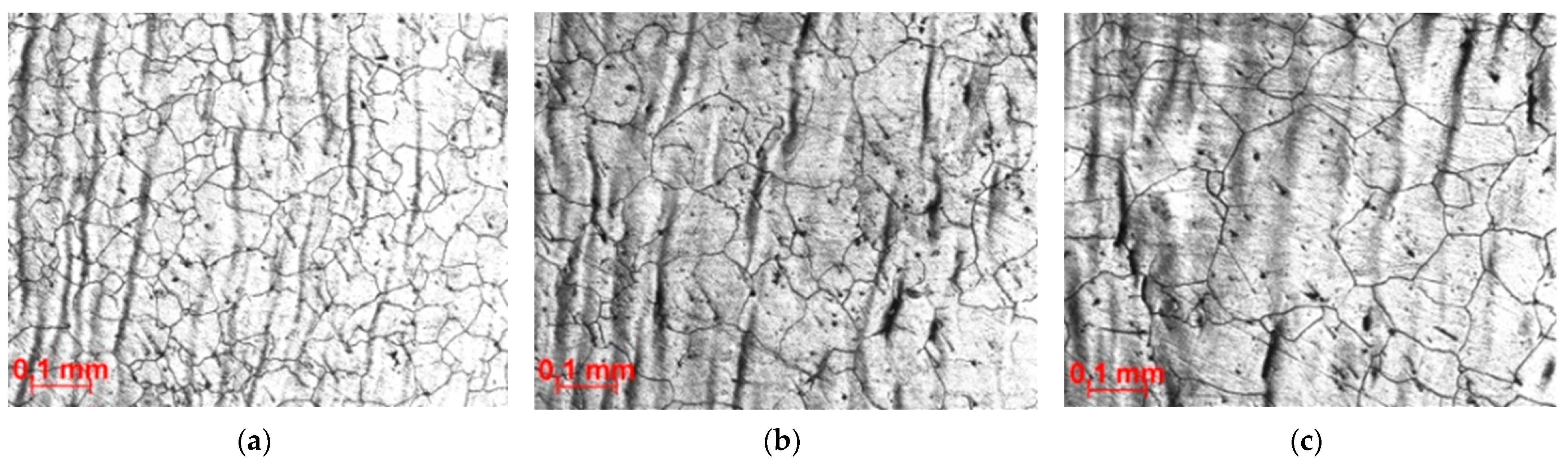
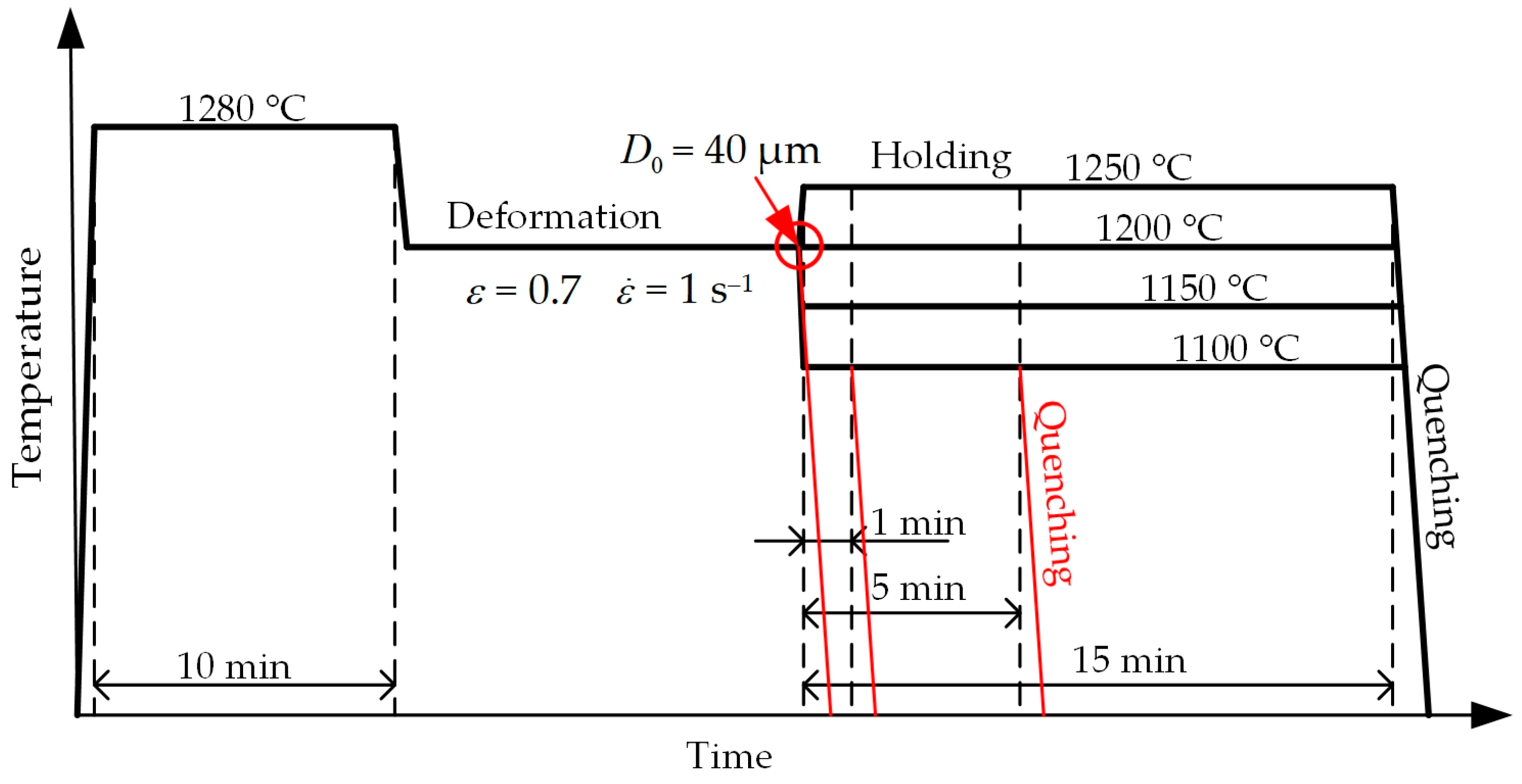
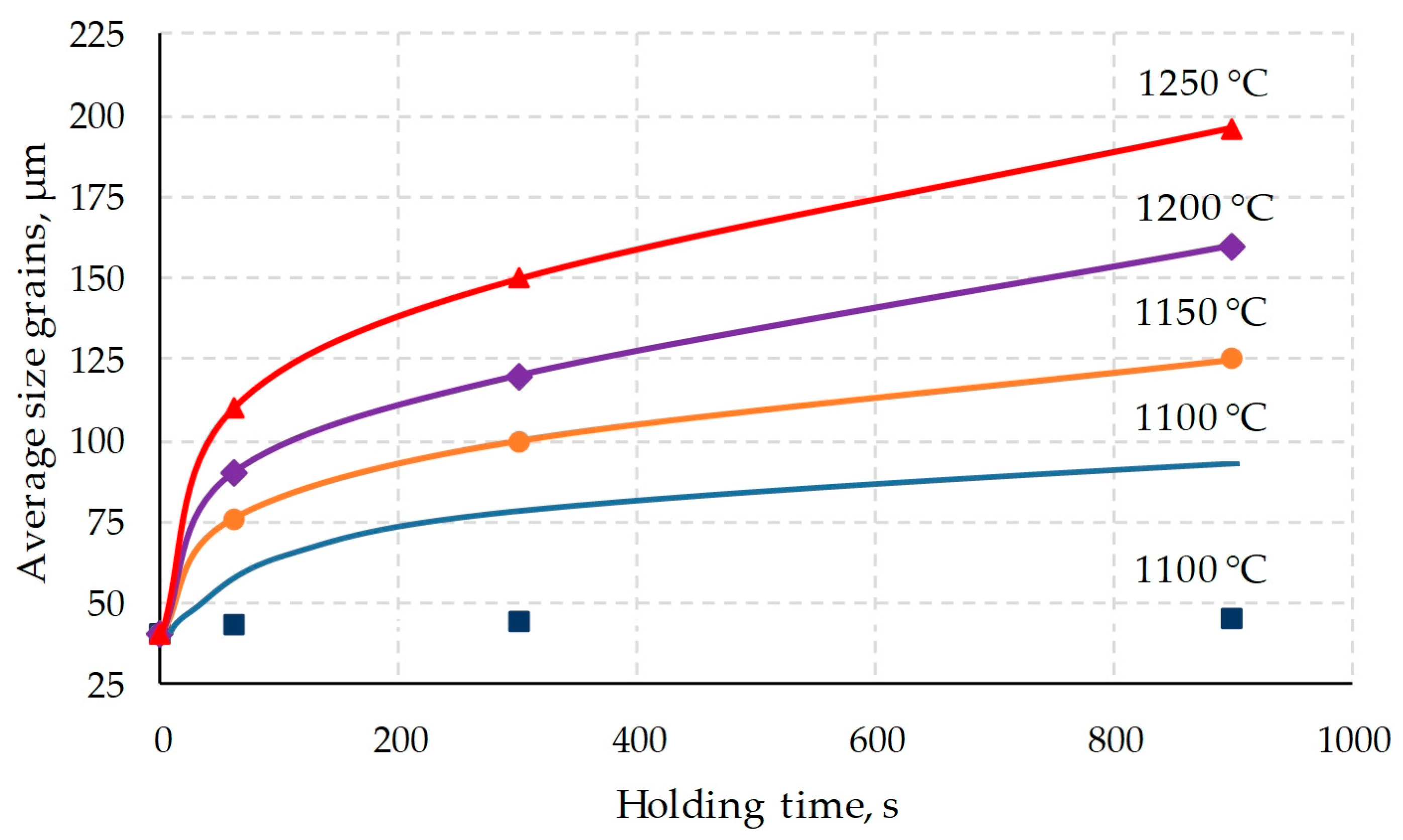
- After holding the steel at a temperature of 1150 °C and above, intensive grain growth is observed. At a temperature of more than 1150 °C and an exposure of more than 5 min, the grain size exceeds a value of 100 μm.
- Reducing the holding temperature to 1100 degrees leads to a sharp drop in the grain growth rate. The suppression of grain growth is caused by the precipitation of titanium carbides and carbonitrides. The average austenite grain size did not exceed 45 µm even after 15 min exposure at 1100 °C.
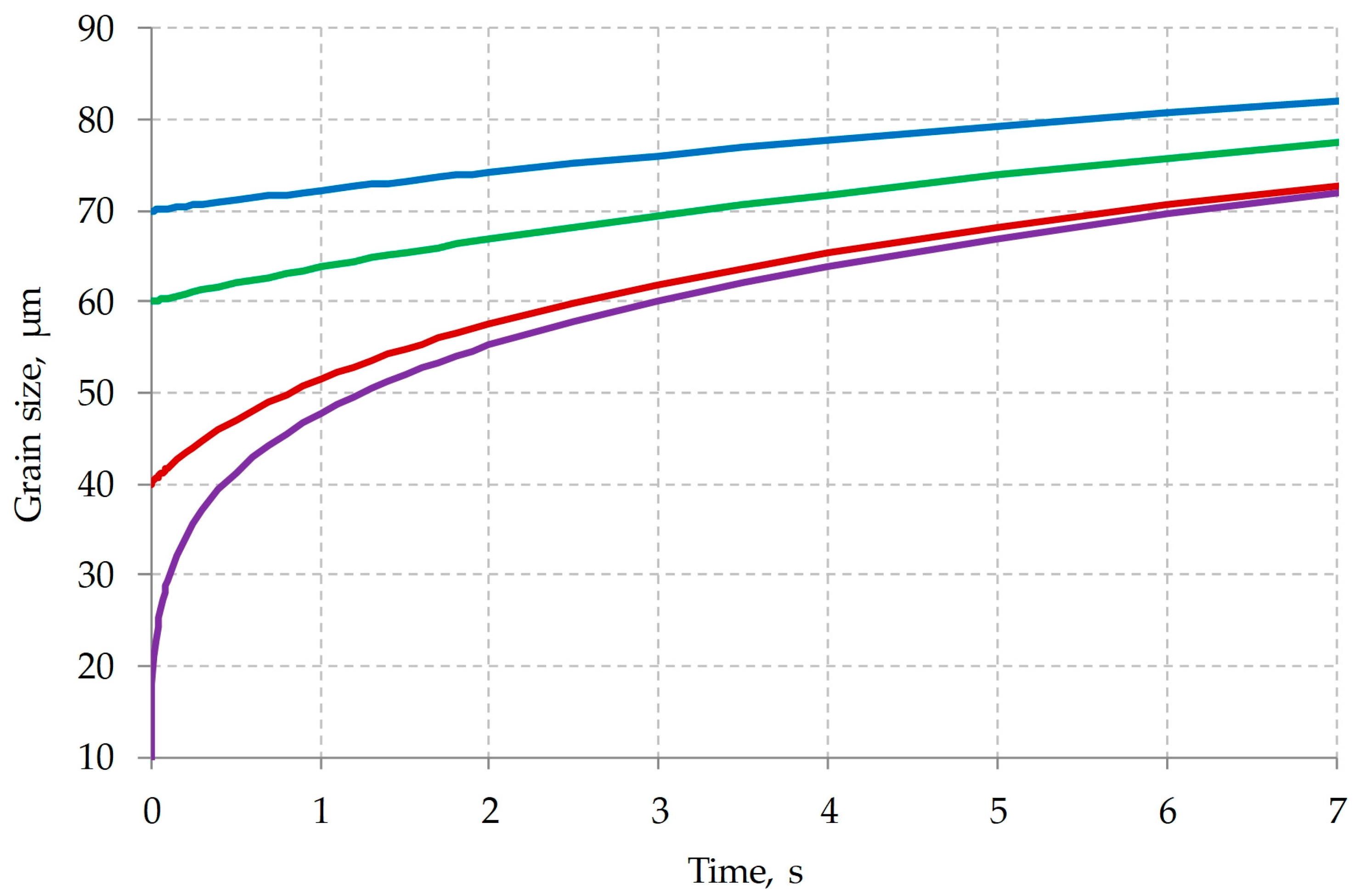
- A dependence is obtained for calculating the kinetics of austenite grain growth for a temperature range of 1150–1250 °C,where —initial grain size, μm; —grain size (μm) at the time , (s); —holding temperature, °C.
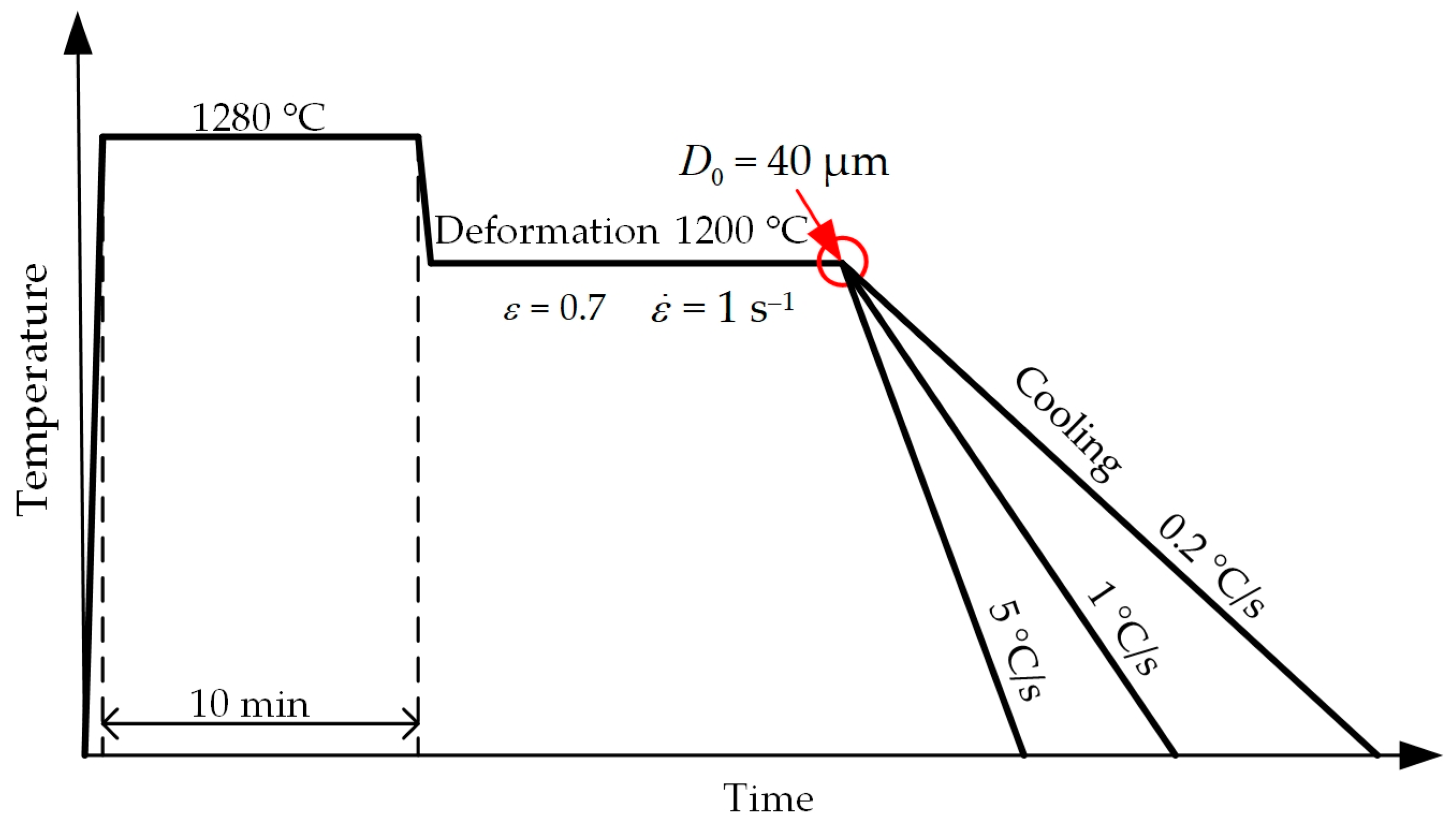
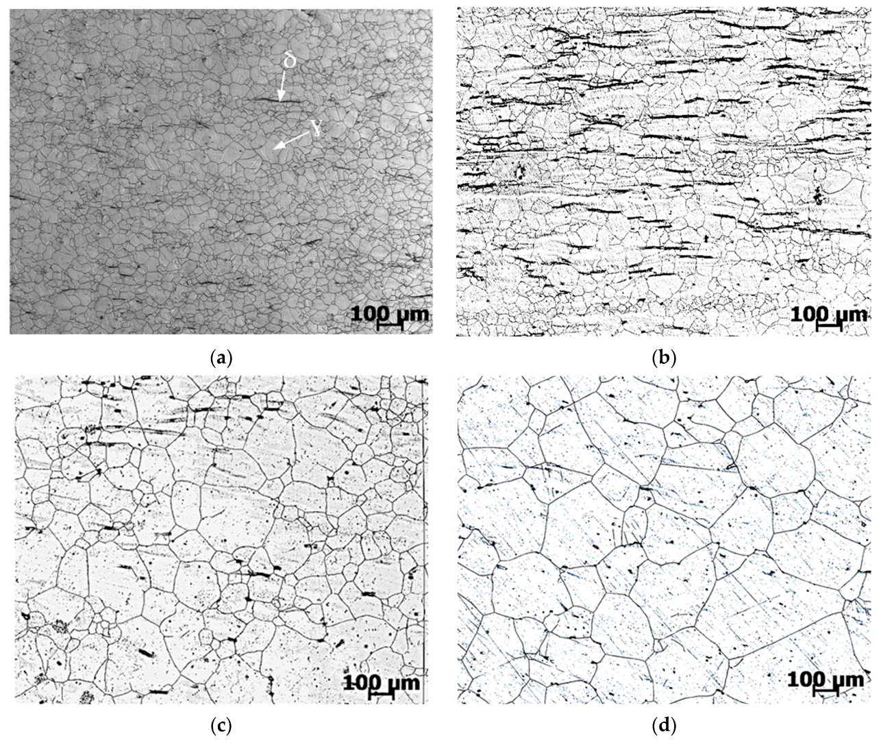
- The proposed dependence makes it possible to evaluate grain growth under non-isothermal conditions. To do this, it is necessary to divide the time into small intervals, within which the temperature changes by a small amount (up to 1 °C). The verification of the adequacy of the proposed dependence and the method for calculating the grain size at cooling rates 0.2, 1 and 5 °C/s showed its high convergence. The difference between the calculated and experimental grain size did not exceed 8%.
- A mathematical model has been developed that combines the solution of the heat conduction equation and the kinetics of grain growth, with the help of which the grain size in the shell after piercing is determined by calculation. The results obtained show that the formation of coarse grains is determined by the kinetics of its post-deformation growth. To obtain a relatively fine-grained microstructure, technological measures should be taken to suppress grain growth.
Author Contributions
Funding
Data Availability Statement
Conflicts of Interest
References
- Arroyo, B.; Lacalle, R.; Álvarez, J.A.; Cicero, S.; Moreno-Ventas, X. Analysis of Unexpected Leaks in AISI 316L Stainless Steel Pipes Used for Water Conduction in a Port Area. Appl. Sci. 2023, 13, 2598. [Google Scholar] [CrossRef]
- Resnik, M.; Benčina, M.; Levičnik, E.; Rawat, N.; Iglič, A.; Junkar, I. Strategies for improving antimicrobial properties of stainless steel. Materials 2020, 13, 2944. [Google Scholar] [CrossRef] [PubMed]
- Cadelano, G.; Bortolin, A.; Ferrarini, G.; Bison, P.; Santa, G.D.; Di Sipio, E.; Bernardi, A.; Galgaro, A. Evaluation of the Effect of Anti-Corrosion Coatings on the Thermal Resistance of Ground Heat Exchangers for Shallow Geothermal Applications. Energies 2021, 14, 2586. [Google Scholar] [CrossRef]
- Zhang, F.; O’mahony, J.A.; Miao, S.; Cronin, K. An Experimental Study on the Dilute Phase Pneumatic Conveying of Fat-Filled Milk Powders: Particle Breakage. Powders 2023, 2, 124–134. [Google Scholar] [CrossRef]
- Bykova, A.E.; Sharipzyanova, G.K.; Volgina, N.I.; Khlamkova, S.S. Methodology of Analyzing the Causes of Accidental Failure of Pipes Made of Various Steel Grades. Russ. Met. 2018, 2018, 1264–1267. [Google Scholar] [CrossRef]
- Cheng, J.; Yan, Q.; Pan, Z.; Wei, W. On-Line Measurement and Characterization of Electrochemical Corrosion of 304L Stainless Steel Pipe Wall in High-Speed Cl-Containing Solution. Metals 2022, 12, 1324. [Google Scholar] [CrossRef]
- Zhao, J.; Qiu, F.; Xu, C. Review of Creep-Thermomechanical Fatigue Behavior of Austenitic Stainless Steel. Crystals 2023, 13, 70. [Google Scholar] [CrossRef]
- Kamaya, M. Failure assessment curve for austenitic stainless steel pipes of nuclear power plants. Eng. Fract. Mech. 2020, 238, 107283. [Google Scholar] [CrossRef]
- Vlčková, I.; Jonšta, P.; Jonšta, Z.; Váňová, P.; Kulová, T. Corrosion Fatigue of Austenitic Stainless Steels for Nuclear Power Engineering. Metals 2016, 6, 319. [Google Scholar] [CrossRef]
- Reddy, G.P.; Sandhya, R.; Sankaran, S.; Parameswaran, P.; Laha, K. Creep–fatigue interaction behavior of 316LN austenitic stainless steel with varying nitrogen content. Mater. Des. 2015, 88, 972–982. [Google Scholar] [CrossRef]
- Wang, J.; Su, H.; Chen, K.; Du, D.; Zhang, L.; Shen, Z. Effect of δ-ferrite on the stress corrosion cracking behavior of 321 stainless steel. Corros. Sci. 2019, 158, 108079. [Google Scholar] [CrossRef]
- Kopylov, V.I.; Nokhrin, A.V.; Kozlova, N.A.; Chegurov, M.K.; Gryaznov, M.Y.; Shotin, S.V.; Melekhin, N.V.; Tabachkova, N.Y.; Smetanina, K.E.; Chuvil’deev, V.N. Effect of σ-Phase on the Strength, Stress Relaxation Behavior, and Corrosion Resistance of an Ultrafine-Grained Austenitic Steel AISI 321. Metals 2023, 13, 45. [Google Scholar] [CrossRef]
- Rybalchenko, O.V.; Anisimova, N.Y.; Kiselevsky, M.V.; Belyakov, A.N.; Tokar, A.A.; Terent’ev, V.F.; Prosvirnin, D.V.; Rybalchenko, G.V.; Raab, G.I.; Dobatkin, S.V. The influence of ultrafine-grained structure on the mechanical properties and biocompatibility of austenitic stainless steels. J. Biomed. Mater. Res. Part B Appl. Biomater. 2020, 108, 1460–1468. [Google Scholar] [CrossRef] [PubMed]
- Tiamiyu, A.A.; Eduok, U.; Szpunar, J.A.; Odeshi, A.G. Corrosion behavior of metastable AISI 321 austenitic stainless steel: Investigating the effect of grain size and prior plastic deformation on its degradation pattern in saline media. Sci. Rep. 2019, 9, 12116. [Google Scholar] [CrossRef]
- Seitl, S.; Horník, V.; Lesiuk, G.; Kunz, L. Influence of Micro-structure of selected components made from AISI 304 on the mechanical properties. Procedia Struct. Integr. 2023, 43, 113–118. [Google Scholar] [CrossRef]
- Rezaei, H.; Ghazani, M.S.; Eghbali, B. Effect of post deformation annealing on the microstructure and mechanical properties of cold rolled AISI 321 austenitic stainless steel. Mater. Sci. Eng. A 2018, 736, 364–374. [Google Scholar] [CrossRef]
- Radionova, L.V.; Perevozchikov, D.V.; Makoveckii, A.N.; Eremin, V.N.; Akhmedyanov, A.M.; Rushchits, S.V. Study on the Hot Deformation Behavior of Stainless Steel AISI 321. Materials 2022, 15, 4057. [Google Scholar] [CrossRef]
- Verlinden, B. Thermo-Mechanical Processing of Metallic Materials; Verlinden, B., Driver, J., Samaidar, I., Doherty, R.D., Eds.; Elsevier: Amsterdam, The Netherlands, 2007; 528p. [Google Scholar]
- Sellars, C.M.; Whiteman, J.A. Recrystallization and grain growth in hot rolling. Met. Sci. 1979, 13, 187–194. [Google Scholar] [CrossRef]
- Harker, D.; Parker, E.R. Grain shape and grain growth. Trans. Am. Soc. Met. 1945, 34, 156–195. [Google Scholar]
- Mats, H. On the theory of normal and abnormal grain growth. Acta Metallurgica. 1965, 13, 227–238. [Google Scholar] [CrossRef]
- Burke, J.E. Some factors affecting the rate of grain growth in metals. Trans. Am. Iwt. Min. (Metall.) Eng. 1949, 180, 73. [Google Scholar]
- Anwar, M.S.; Pradisti, M.G.; Candra, S.A.; Martides, E.; Mabruri, E.; Siradj, E.S. Grain growth kinetics of austenitic stainless steel 316L and the relations between grain sizes and hardness under isothermal conditions. Metalurgi 2022, 37, 15–20. [Google Scholar] [CrossRef]
- Mat, M.F.; Manurung, Y.H.P.; Busari, Y.O.; Adenan, M.S.; Sulaiman, M.S.; Muhammad, N.; Graf, M. Experimental Analysis on Grain Growth Kinetics of SS316L Austenitic Stainless Steel. J. Mech. Eng. 2021, 18, 97–111. [Google Scholar] [CrossRef]
- Annan, K.; Siyasiya, C.; Stumpf, W.; Banks, K.; Tuling, A. Austenite Grain Growth Kinetics in a Low C-Mn Steel and a Ti-Nb-V Microalloyed Steel. Adv. Mater. Res. 2014, 1019, 327–332. [Google Scholar] [CrossRef]
- Manohar, P.A.; Dunne, D.P.; Chandra, T.; Killmore, C.R. Grain Growth Predictions in Microalloyed Steels. ISIJ Int. 1996, 36, 194–200. [Google Scholar] [CrossRef]
- Huda, Z.; Zaharinie, T. Kinetics of grain growth in 2024-T3: An aerospace aluminum alloy. J. Alloy. Compd. 2009, 478, 128–132. [Google Scholar] [CrossRef]
- Huang, Y.-C.; Su, C.-H.; Wu, S.-K.; Lin, C. A Study on the Hall–Petch Relationship and Grain Growth Kinetics in FCC-Structured High/Medium Entropy Alloys. Entropy 2019, 21, 297. [Google Scholar] [CrossRef]
- Alizadeh, R.; Mahmudi, R.; Ngan, A.H.W.; Langdon, T.G. Microstructural stability and grain growth kinetics in an extruded fine-grained Mg–Gd–Y–Zr alloy. J. Mater. Sci. 2015, 50, 4940–4951. [Google Scholar] [CrossRef]
- Rath, B.B.; Lederich, R.J.; Yolton, C.F.; Froes, F.H. Recrystallization and grain growth in metastable beta III titanium alloy. Met. Trans. A 1979, 10, 1013–1019. [Google Scholar] [CrossRef]
- Fei, Y.; Wang, X.N.; Zhu, Z.S.; Li, J.; Shang, G.Q.; Zhu, L.W. β Grain Growth Kinetics of a New Metastable β Titanium Alloy. Mater. Sci. Forum 2013, 747–748, 844–849. [Google Scholar] [CrossRef]
- Mishra, S.; DebRoy, T. Non-isothermal grain growth in metals and alloys. Mater. Sci. Technol. 2006, 22, 253–278. [Google Scholar] [CrossRef]
- Uhm, S.; Moon, J.; Lee, C.; Yoon, J.; Lee, B. Prediction Model for the Austenite Grain Size in the Coarse Grained Heat Affected Zone of Fe-C-Mn Steels: Considering the Effect of Initial Grain Size on Isothermal Growth Behavior. ISIJ Int. 2004, 44, 1230–1237. [Google Scholar] [CrossRef]
- De Sousa, R.C.; Filho, J.C.C.; Tanaka, A.A.; de Oliveira, A.C.S.; Ferreira, W.E.I. Effects of solution heat treatment on grain growth and degree of sensitization of AISI 321 austenitic stainless steel. J. Mater. Sci. 2006, 41, 2381–2386. [Google Scholar] [CrossRef]
- Ghazani, M.S.; Eghbali, B.; Ebrahimi, G. Kinetics and critical conditions for initiation of dynamic recrystallization during hot compression deformation of AISI 321 austenitic stainless steel. Met. Mater. Int. 2017, 23, 964–973. [Google Scholar] [CrossRef]
- Goldstein, M.I. Special Steels: Textbook for Universities; Goldstein, M.I., Grachev, S.V., Veksler, Y.G., Eds.; MISiS: Moscow, Russia, 1999; 408p. [Google Scholar]
- Mandal, S.; Bhaduri, A.K.; Sarma, V.S. Influence of State of Stress on Dynamic Recrystallization in a Titanium-Modified Austenitic Stainless Steel. Met. Mater. Trans. A 2012, 43, 410–414. [Google Scholar] [CrossRef]
- Kratochvíl, P.; Lukáč, P.; Vostrý, P.; Pacák, J.; Tomeš, J. Dynamic softening and static recrystallisation of AISI 321 steel. Mater. Sci. Technol. 1991, 7, 78–82. [Google Scholar] [CrossRef]
- Perevozchikov, D.V. Improvement of Manufacturing Technology Hot-Rolled Pipe from Steel Grade 08KH18N10T to Improve the Structure 2.6.4—Metal Forming: Dissertation Degree of Candidate of Technical Sciences; Danil Viktorovich Perevozchikov: Chelyabinsk, Russia, 2022; 161p. [Google Scholar]
- Solodov, A.P. Heat and Mass Transfer in Power Plants. Engineering Methods of Calculation. Electronic Resource [Text]: Textbook on the Courses “Heat and Mass Transfer in NPP Equipment” for Students Studying in the Areas of “Nuclear Energy and Thermal Physics” and “Heat Power Engineering and Heat Engineering”/A.P. Solodov; MEI Publishing House: Moscow, Russia, 2015; 124p, ISBN 978-5-046-1636-8. [Google Scholar]
- Available online: http://jmatpro.ru/ (accessed on 31 May 2023).
- Samarsky, A.A. Computational Heat Transfer; Samarsky, A.A., Vabishchevich, P.N., Eds.; Editorial URSS: Moscow, Russia, 2003; 784p. [Google Scholar]
- Kuznetsov, G.V. Difference Methods for Solving Problems of Heat Conduction; Kuznetsov, G.V., Sheremet, M.A., Eds.; Publishing House of the Tomsk Polytechnic University: Tomsk, Russia, 2007; 172p. [Google Scholar]
- Rushchits, S.V.; Akhmed’yanov, A.M.; Perevozchikov, D.V.; Makovetskiy, A.N.; Eremin, V.N. Modelling of Hot Deformation of Steel 08H18N10T (AISI 321) under Uniaxial Compression Test. Bull. South Ural. State University. Ser. Metall. 2021, 21, 30–41. (In Russian) [Google Scholar]
- Eremin, V.N.; Perevozchikov, D.V.; Makovetskiy, A.N.; Shakirova, L.I.; Rushchits, S.V. Formation of the Structure of Steel 08KH18N10T during Pilgrim Rolling and Following Annealing. Bull. South Ural. State University. Ser. Metall. 2021, 21, 78–86. (In Russian) [Google Scholar] [CrossRef]


| C | Si | Mn | Cr | Ni | S | P | Mo | Cu | Ti | N |
|---|---|---|---|---|---|---|---|---|---|---|
| 0.07 | 0.30 | 1.33 | 17.7 | 10.3 | 0.005 | 0.025 | 0.19 | 0.19 | 0.50 | 0.014 |
| Holding Temperature, °C | 1100 | 1150 | 1200 | 1250 | ||||||||
|---|---|---|---|---|---|---|---|---|---|---|---|---|
| Holding time, min | 1 | 5 | 15 | 1 | 5 | 15 | 1 | 5 | 15 | 1 | 5 | 15 |
| Average size grains, μm | 43 | 44 | 45 | 76 | 100 | 125 | 90 | 120 | 160 | 110 | 150 | 196 |
| Cooling Rate, °C/s | Experimental Grain Size (Average), μm | Calculated Grain Size, μm | Difference between Calculated and Experimental Value, % |
|---|---|---|---|
| Quenching (immediately cooling) | 40 | - | - |
| 5 | 55 | 60 | 8 |
| 1 | 75 | 82 | 8 |
| 0.2 | 108 | 114 | 5 |
Disclaimer/Publisher’s Note: The statements, opinions and data contained in all publications are solely those of the individual author(s) and contributor(s) and not of MDPI and/or the editor(s). MDPI and/or the editor(s) disclaim responsibility for any injury to people or property resulting from any ideas, methods, instructions or products referred to in the content. |
© 2023 by the authors. Licensee MDPI, Basel, Switzerland. This article is an open access article distributed under the terms and conditions of the Creative Commons Attribution (CC BY) license (https://creativecommons.org/licenses/by/4.0/).
Share and Cite
Radionova, L.V.; Perevozchikov, D.V.; Makoveckii, A.N.; Eremin, V.N.; Akhmedyanov, A.M.; Rushchits, S.V. Grain Growth during Mechanical Processing of Austenitic Stainless Steel AISI 321. Metals 2023, 13, 1421. https://doi.org/10.3390/met13081421
Radionova LV, Perevozchikov DV, Makoveckii AN, Eremin VN, Akhmedyanov AM, Rushchits SV. Grain Growth during Mechanical Processing of Austenitic Stainless Steel AISI 321. Metals. 2023; 13(8):1421. https://doi.org/10.3390/met13081421
Chicago/Turabian StyleRadionova, Liudmila V., Danil V. Perevozchikov, Aleksandr N. Makoveckii, Victor N. Eremin, Alexander M. Akhmedyanov, and Sergey V. Rushchits. 2023. "Grain Growth during Mechanical Processing of Austenitic Stainless Steel AISI 321" Metals 13, no. 8: 1421. https://doi.org/10.3390/met13081421
APA StyleRadionova, L. V., Perevozchikov, D. V., Makoveckii, A. N., Eremin, V. N., Akhmedyanov, A. M., & Rushchits, S. V. (2023). Grain Growth during Mechanical Processing of Austenitic Stainless Steel AISI 321. Metals, 13(8), 1421. https://doi.org/10.3390/met13081421