Abstract
This paper presents an analysis of the fracture accident of a cylindrical roller bearing cage used in a charging pump in a nuclear power plant. The causes and mechanisms of bearing cage breakage were investigated by material failure analysis and simulation calculations. Macroscopic observation results confirmed that the cage fracture occurred at the stress concentration position. The microfracture morphology of the cage obtained from scanning electron microscopy showed a fatigue feature. The analysis of residual stress indicated large residual stress perpendicular to the fracture surface. The finite element calculation showed that when the bearing was moving in and out of the working area during operation, large working stress appeared at the stress concentration position. Working stress and residual stress acted together, approaching the fatigue limit of materials, and finally led to the cage fatigue fracture. The stress of the other two structural cages of the same type of bearing was also calculated, and no such large stress concentration was identified; thus, one plastic cage was temporarily used.
1. Introduction
Charging pumps are important nuclear safety equipment in second-generation pressurized water reactor (PWR) nuclear power plants. The charging pump in this work is designed by the KSB Pump Valve Group of Germany, and the model is RHM 100–205.12. It is a one-way, horizontal, 12-stage centrifugal pump. The non-drive end of the pump utilizes a cylindrical roller thrust bearing and employs an external circulating oil lubrication system. The drive end of the pump utilizes a radial cylindrical roller bearing and employs oil bath lubrication. The cross-sectional diagram of the pump and the structure of the drive-end bearing housing are shown in Figure 1a,b. The bearing model used at the drive end is SKF NU312 ECJ. This bearing is characterized by no rib on the inner ring, allowing the pump shaft to move slightly along the axial direction, and it adopts a stamped steel cage.
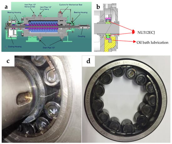
Figure 1.
Pump structure and condition of the drive-end bearing damage. (a) Cross-sectional structure of the charging pump. (b) Cross-sectional structure of the drive-end bearing housing. (c) Disassembling the pump reveals a bearing failure. (d) Faulty bearing and the cage with multiple breaks.
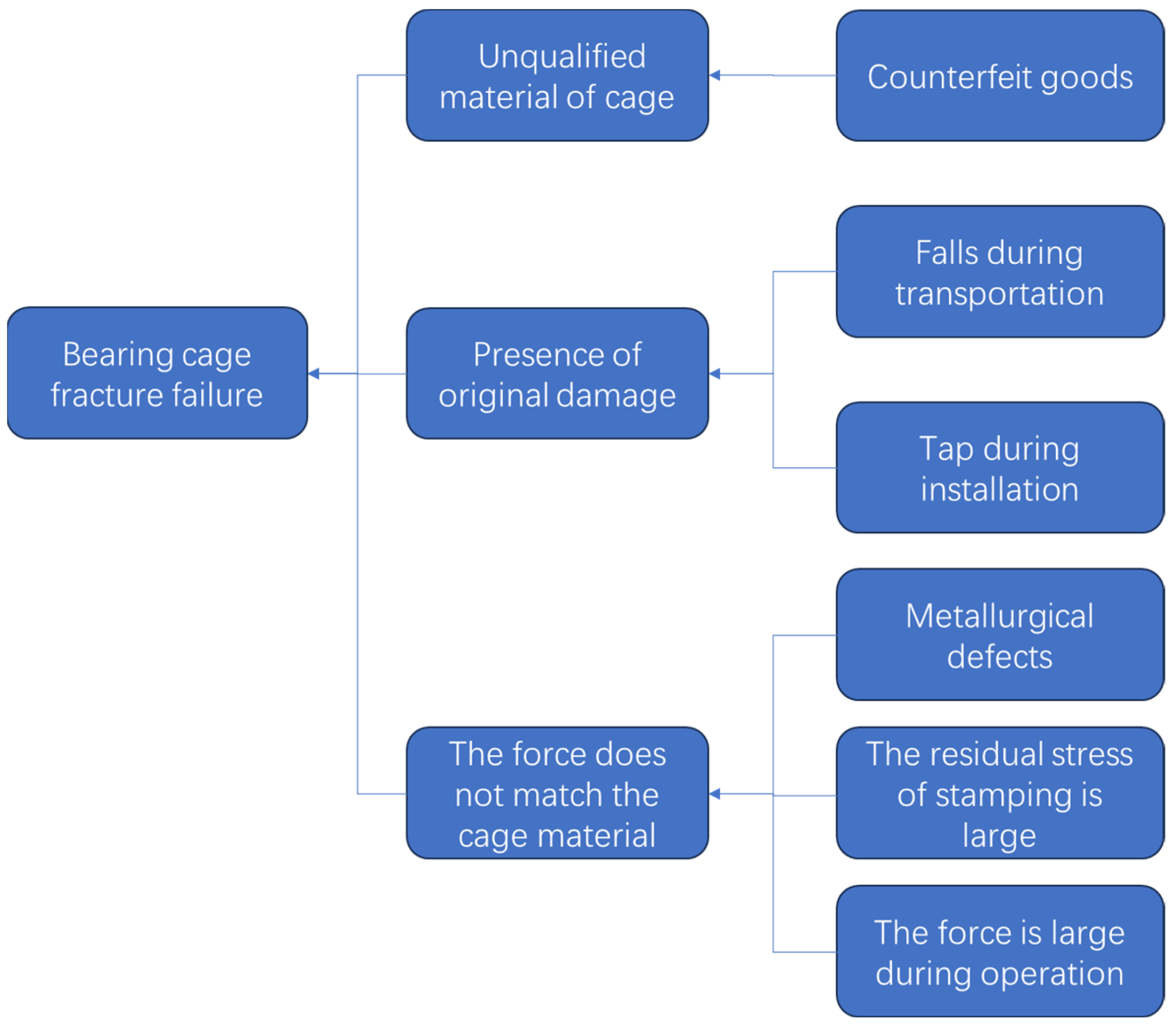
Each nuclear power unit is equipped with three charging pumps, with one pump serving as a backup. The remaining two pumps alternate operation every 2 weeks. The failed charging pump had been in operation for approximately 14 months, starting approximately 30 times, with a cumulative running time of approximately 5040 h. During this period, a fracture occurred in the drive-end bearing housing, leading to severe bearing damage, as shown in Figure 1c,d. Similar incidents of drive-end bearing cage failure have been experienced multiple times in the history of this particular model of charging pump. The bearing cage fracture includes many possible failure modes. The common failure modes are fatigue fracture [1,2,3], wear fracture [4,5,6,7], overload fracture [8,9,10], and misalignment [11]. The causes of fatigue fracture include unqualified material of the cage itself, installation damage to the cage, and excessive force on the cage. Many scholars have studied the fracture causes of various bearing cages. Evaluating the failure mode and causes of bearing cages and proposing suggestions can reduce the damage of bearing cages and avoid or decrease the accident costs of the related factories.
Bearing cage fracture cases have been reported since the 1940s; in particular, bearing misalignment caused several cage fracture cases in the Royal Air Force [12]. Numerous early cases of bearing cage fracture are related to the aero-engine, focusing on fatigue crack initiation [2] and experimental confirmation [13]. In other areas, Wang analyzed the effects of axial, radial, and tilt misalignments on the dynamic characteristics of the planetary gear set-rotor system [14]. Wei identified the nature and causes of deterioration and failure in dental handpiece ball bearings and concluded that cage fracture may be a key factor limiting bearing life, given that cages can be damaged easily [15]. A case in an automobile showed that the wear behavior of the mandrel originated from the surface fatigue and the failure was attributed to the large radial deflection load [3].
In consideration of the complex shape of cages and the changing force in operation, the finite element analysis method is usually applied to study the force and fracture causes of the cage. Based on the elastic theory, Sakaguchi et al. [16] established a dynamic analysis model of a needle roller bearing using ADAMS and analyzed the maximum stress of the needle roller bearing cage. The analysis results indicated large stress in the bearing area, but the maximum stress point of the cage was in the non-working area. Nogi et al. [17] studied the cage motion in ball bearings by using a dynamic analysis program. The results showed that the increase in the cage friction coefficient led to the unstable motion of the cage. Under the conditions of high load and low speed, instability would likely occur because of small-ball sliding. Deng et al. [18] developed a rigid flexible multibody dynamic analysis program for angular contact ball bearings by using the ADAMS system to analyze the dynamic performance of the cage of a high-speed angular contact ball bearing. The analysis results showed that a too-large or too-small ratio of the radial load to the axial load of the angular contact ball bearing was not conducive to the stability of the cage rotation. Compared with the rigid cage, the flexible cage rotated more smoothly. Feng [19] established a finite element model of an angular contact ball bearing based on Abaqus and carried out a dynamic simulation by applying different speeds and loads. When the radial load of the bearing increased, the stability of the cage decreased, and the influence of the radial load on the dynamic characteristics of the cage was greater than that of the axial load.
In this study, fracture analysis, metallographic analysis, chemical composition analysis, and residual stress analysis of a fractured bearing cage were conducted using material failure analysis technology. At the same time, the force on different bearing cages was calculated via finite element analysis technology, and the failure reason was determined. Based on the comparison of the stress concentrations of structure-updated cages and material-updated cages under the same working conditions, temporary improvement measures for the bearing cage were proposed.
2. Investigative and Analysis Methods
2.1. Failure Investigation Process
With the participation and support of various specialized departments within the nuclear power plant, a comprehensive investigation and analysis were conducted by a team as follows:
- (1)
- Investigation of the bearing procurement channel and confirmation with SKF to ensure the authenticity of the bearing.
- (2)
- Collection of detailed information regarding the pump failure process, historical operational data, maintenance records, and experiences with similar equipment failures.
- (3)
- List and analysis of possible failure modes for the bearing failure, as depicted in Figure 2.
 Figure 2. Possible failure modes for the damaged bearing cage.
 - (4)
- Designing protocols for metallurgical experimental studies based on the identified failure modes.
- (5)
- Perform analysis work on the fractured bearing cage sample and summarize and analyze all the obtained data.
- (6)
- Analyze the operating conditions of the bearing, establish boundary conditions, and utilize finite element calculation and analysis software to assess the forces acting on the bearing cage.
- (7)
- Explore corrective action plans aimed at preventing the recurrence of bearing failures.
2.2. Metallological Analysis Process
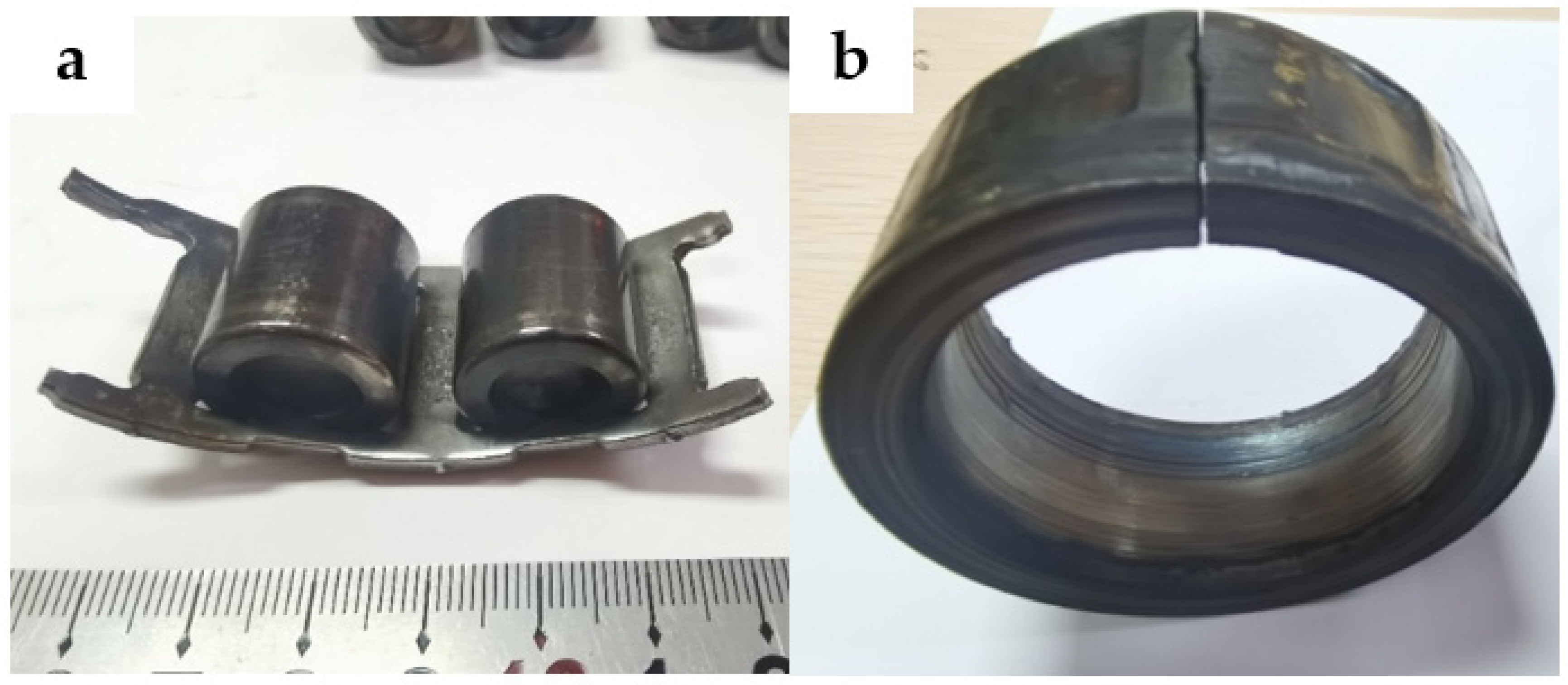
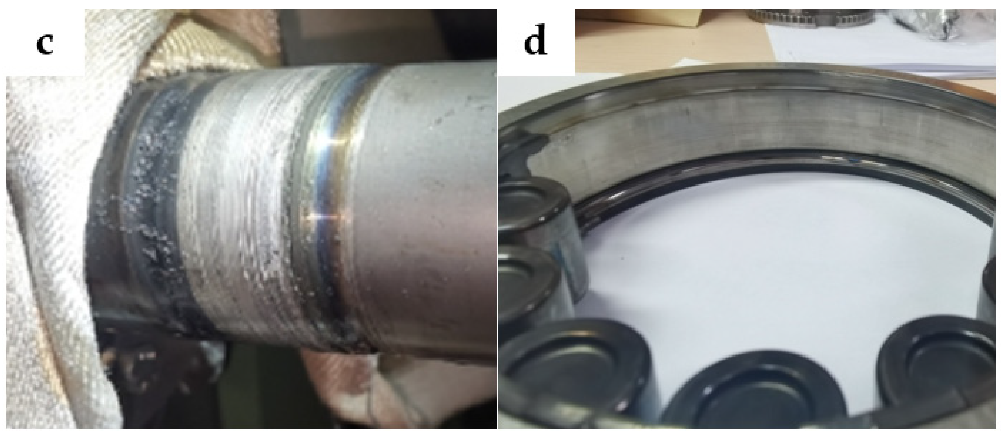
In this bearing failure event, the bearing cage was fractured, as shown in Figure 3a. In addition to the cage fracture, the failures of other parts of the bearing and adjacent parts also occurred. The bearing inner ring exhibits cracks and overheating, depicted in Figure 3b. A running circle occurs between the bearing inner ring and the pump shaft, illustrated in Figure 3c. However, the outer ring of the bearing remains intact without any apparent damage, as depicted in Figure 3d.
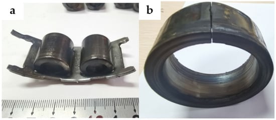
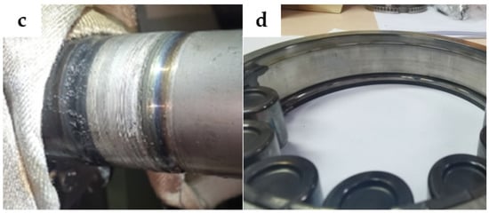
Figure 3.
Fault conditions of components. (a) Bearing outer race raceway. (b) Broken bearing cage. (c) Overheated and broken bearing inner race. (d) Wear marks on pump shaft.
However, based on the empirical feedback from multiple incidents of bearing cage fracture failures in the charge pump, it is preliminarily inferred that the bearing cage remains the component responsible for the bearing failure in this case. Accordingly, the progression of the bearing failure can be described as follows: Firstly, the bearing cage fractures, resulting in roller slippage and a consequent rapid increase in the temperature of the bearing inner ring. Since the bearing inner ring is installed with a thermal interference fit, when the bearing temperature exceeds 80 °C, the fit between the bearing inner ring and the pump shaft transitions from an interference fit to a clearance fit. This transition leads to a reduction in friction between the two components, causing the inner ring of the bearing to run, resulting in more severe damage to both the bearing and the pump shaft.
A metallographic failure analysis route was designed to address the failure mode of the bearing cage fracture. Firstly, a macroscopic inspection was conducted to identify the fracture location of the cage. Secondly, microscopic observation and analysis of the fracture surface were performed to determine the fracture characteristics of the cage and analyze its stress patterns. By combining the results of microcosmic and macrocosmic analogical observations, the presence of initial damage was confirmed, which helped to investigate whether the bearing has incurred damage during transportation and installation. Subsequently, component analysis and metallographic examination were conducted on the bearing cage to ascertain the presence of metallurgical defects and further determine the material grade of the bearing cage. Lastly, the residual stress of the bearing cage was detected and analyzed to identify the presence of machining defects within the bearing. Based on the stress experienced during operation, a comprehensive evaluation is conducted to assess the impact of the cage fracture fault.
2.3. Calculation Condition of Working Stress of Bearing Cage
In consideration of the complex force relationship between the roller and the cage, the friction between the inner ring and the roller, the centrifugal force of the roller, the friction of the outer ring raceway, the centrifugal force of the cage, and the collision motion between the cage and the roller should be considered simultaneously. In this study, the finite element calculation method was used, and Abaqus simulation software was utilized to simulate the force of the bearing cage in motion.
According to the feedback from the KSB pump manufacturer, the drive-end bearing of the charging pump could withstand a radial load of 725 N under low-flow conditions. The bearing operated at a speed of 4657 rpm. The selection of friction coefficient was based on the internal data of SKF and the contact principle of hard steel and soft steel. Table 1 shows the calculation parameters.

Table 1.
Selected working conditions for the working stress calculation.
Given that Young’s modulus, the density, and Poisson’s ratio of different steels are close, the material parameters are the same. In this study, Young’s modulus of the material was 210 GPa, the density was 7850 kg/m3, and Poisson’s ratio was 0.3.
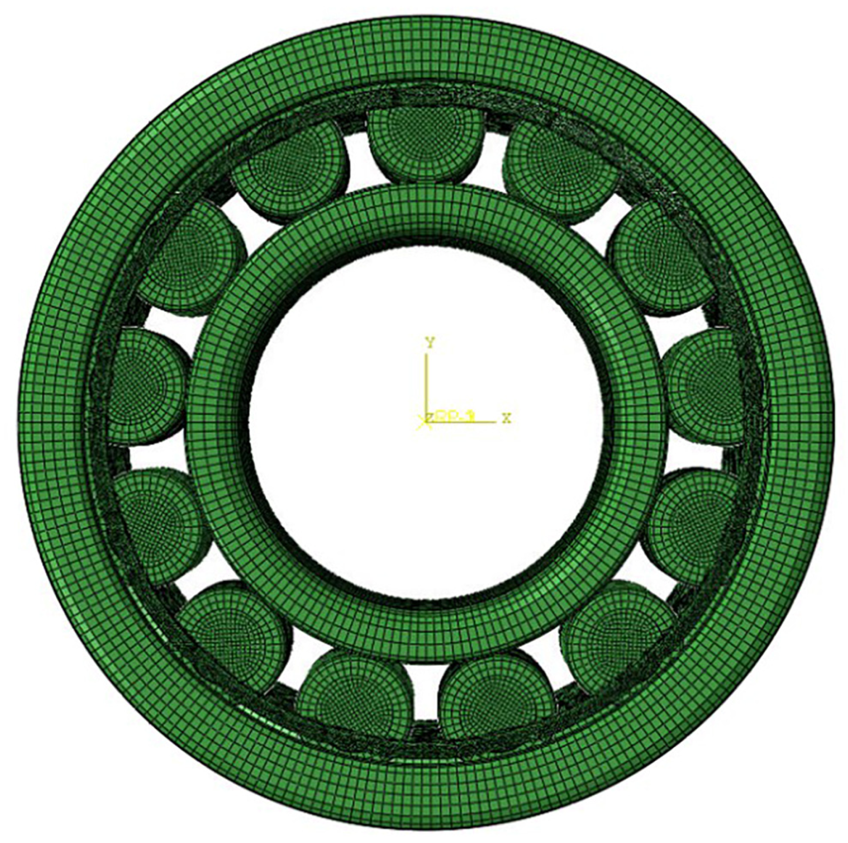
The inner ring, outer ring, and roller of the bearing were meshed with 1.5 mm hexahedral elements (C3D8R). The cage was separately densified with 0.5 mm C3D10M elements, with a total number of 404,116 units, as shown in Figure 4.
Figure 4.
Bearing grid.
The inner surface of the outer ring and the retaining edge established contact with the outer surfaces of the roller, inner ring, roller, cage ring, and roller. The default hard contact was used for normal contact, and the penalty function was adopted for tangential contact.
The outer circle constrained all degrees of freedom, and the inner circle constrained the Z degrees of freedom (axial degrees of freedom). The roller and cage released all degrees of freedom.
3. Results and Discussion
3.1. Fracture Morphologies Analysis of Bearing Cage
The damaged bearing cage was visually observed using a stereoscope (LEICA DMS 1000, LEICA Inc., Weztlar, Germany). The cage had eight breaks altogether. This location did not come into contact with the bearing rollers, as shown in Figure 5a,d. They occurred at the corner of the stamping depression of the holder, which was the stress concentration area. Many studies in the literature reported that damages always occur at the weak site of a device such as a corner area with high stress, e.g., Brooks’ work shows that sharp turns or corners within a structure lead to local failures well before the rest of the structure due to the creation of stress concentrations [20]; Sun calculated the stress around the corner, and their prediction method can provide a good result on the residual life of the structure [21].
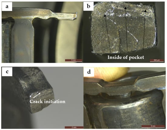
Figure 5.
Macromorphology of the fractured cage. (a) Corner fracture location. (b) Cross-section of the unworn fracture. (c) Macromorphology around the unworn fracture. (d) Wear position of the cage and roller.
No necking was observed in any of the fractures, seven of which were severely worn, and typical fracture characteristics could not be obtained. Only one section showed fracture characteristics. The fracture surface was smooth and had no plastic deformation. The preliminary analysis suggested that it was a fatigue fracture. The crack initiation was located on the inside of the pocket and showed a line initiation, as depicted in Figure 2b, which is inconsistent with a former study [22]. The crack extended to the outside diameter of the pocket and had a large spreading surface.
No visible signs of damage were observed around the crack initiation, indicating that no external force damage affected the initiation of cracking, as shown in Figure 5c. Hence, no improper procedures existed during the bearing installation, and no initial damage occurred.
Wear marks were observed at the corresponding positions of all pocket punching lugs and grooves on the end face of the roller, but this was not the fracture position of the holder, as illustrated in Figure 5d.
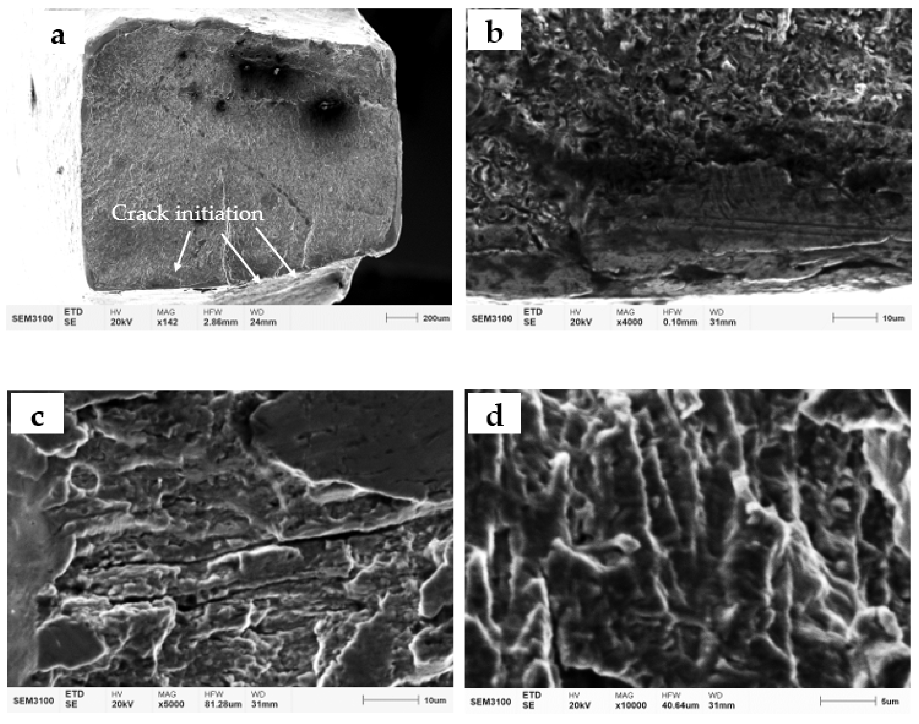
After the cage fracture was cleaned, surface morphology observation was performed using a scanning electron microscope (CIQTEK SEM3100, CIQTEK Ltd., Hefei, China). The main crack initiation of the cage fracture was located on the inner side of the pocket, which was a line initiation, as shown in Figure 6a. No metallurgical defects and machining marks were found in the crack initiation, and the crack extended along the wall thickness to the outer side of the pocket, as presented in Figure 6b. Arc lines and a large number of fine fatigue bands were visible in the expansion area, as shown in Figure 6c,d, and the fatigue expansion area was more than 95%. Thus, the failure of the bearing cage was attributed to fatigue fracture. The secondary crack initiation area was identified outside the pocket hole, indicating that this fracture had multi-initiation crack initiation [23,24].

Figure 6.
Micromorphology of the fractured cage. (a) Crack initiation. (b) Micromorphology of the crack initiation. (c) Micromorphology of the expansion area. (d) High-magnification morphology of the expansion area.
3.2. Chemical Composition Analysis of Bearing Cage
Metal filings were drilled from the failure cage and used for chemical composition analysis. The results are presented in Table 2. The base element of the material was Fe, and the total amount of alloying elements was relatively low. The material content was 0.22 wt.% Mn, 0.044 wt.% C, and small amounts of Cr, Ni, Cu, Si, P, S, and other elements. Public information indicates that the SKF bearing stamped steel cages comply with the DIN EN 10111: 2008 standard [25]. The measured chemical composition results in this instance showed slight deviations from the values specified in the standard. According to the standard, the higher-performance grade DD11 has a yield strength ReL ranging from 170 MPa to 340 MPa and an ultimate tensile strength Rm of 440 MPa. In comparison, the lower-performance grade DD14 has a yield strength ReL ranging from 170 MPa to 290 MPa and an ultimate tensile strength Rm of 380 MPa. However, based on the measurements of the historical bearing cage samples, the ultimate tensile strength Rm of the two specimens was found to be 558 and 577 MPa, respectively.
Table 2.
Chemical composition of the bearing cage (wt.%).
3.3. Observation of Metallographic Structure of Bearing Cage
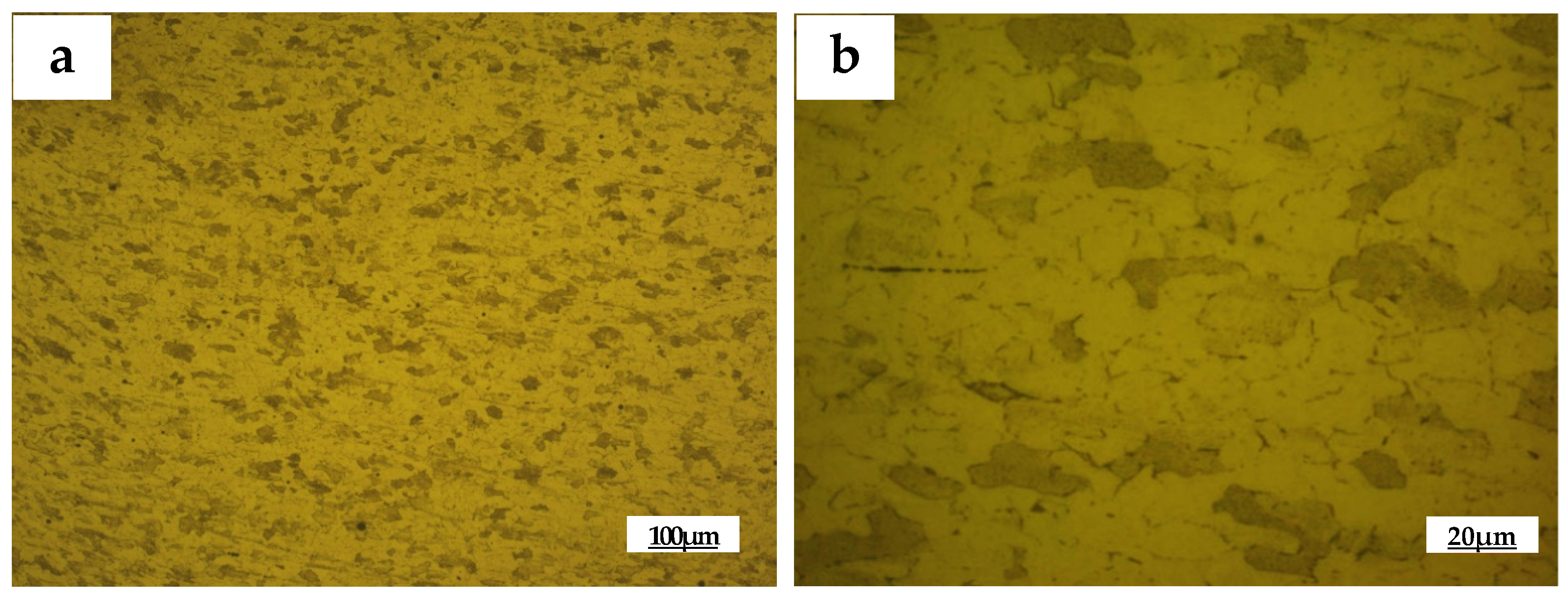
The metallographic sample was collected from the punching depression area of the cage pocket, and the metallographic observation was carried out after grinding, polishing, and etching by using a metallographic microscope (OLYMPUS GX51, OLYMPUS Inc., Tokyo, Japan), as shown in Figure 7. The light phase was ferrite, while the dark phase was granular pearlite, which is the typical structure of carbon steel. No obvious microstructure defects were found in the bearing cage material.
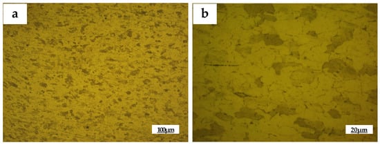
Figure 7.
Metallographic appearance of the cage. (a) 100×. (b) 500×.
3.4. Hardness Test of The Bearing Cage and Roller
Hardness samples of the bearing cage and roller were prepared, and the hardness was tested using a microhardness tester after grinding and polishing (QNESS Q10A+, QATM Ltd., Golling, Austria). The load was 200 g, and the dwell time was 10 s in the test. The results in Table 3 indicate that the average hardness of the roller was 478 HV, and the average hardness of the cage was 164 HV. The hardness of the cage was much lower than that of the roller. This is normal in the design of bearings, and in some cases, brass was used as the bearing cage, whose hardness is much lower than steel [26].
Table 3.
Hardness of the bearing roller and cage (HV).
3.5. Residual Stress Test at Stamping Position of Bearing Cage
A residual stress test was performed on the punching depression of the intact pocket of the cage via the X-ray stress determination method (XL-640 X-ray Stress Analyzer, Handan Este Stress Technology Co., Ltd., Handan, China), and the test results are listed in Table 4. A significant variation in residual stress at different locations, ranging from 7 MPa to 142 MPa, was observed. The lower values might be attributed to the release of residual stress caused by localized high temperatures experienced by the retaining bracket during the accident process. The fracture of the metal components is always related to the local existence of the residual stress. Schlicht pointed out that rolling contact fatigue is a very complex process, in which the microstructure will be changed by micro- and macro-plastic deformation during the fatigue period [27]. By using in situ neutron diffraction and a finite element modeling method, Wang’s results elucidated the distinctive role of plastic deformation and stress triaxiality in ductile fracture initiation between alloys [28]. Huang’s recent work showed that the as-extruded alloy that consists of coarse and fine grains with higher residual stress has low fracture toughness [29]. Shoemaker’s analyses revealed that quench-induced residual stress in the round rod can promote a non-planar, 3D crack path with closure effects [30]. In weld joints, damage also always occurs at the site with high residual stress [31,32]. Based on these valuable works before, it is reasonable to believe that the locations with high residual stress, such as location 3 in this work, are the preferred fracture sites.
Table 4.
Residual stress in the punching depression of the intact pocket of the cage (MPa).
3.6. Calculation Results of Working Stress of Bearing Cage
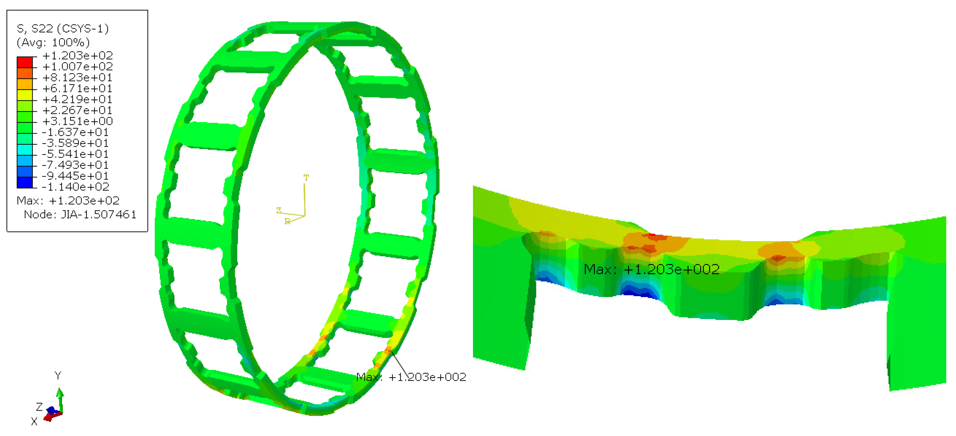
The calculation results are shown in Figure 8. When the roller entered the working area, the maximum tensile stress of the bearing cage reached 120 MPa under the working conditions of 725 N load and 4657 r/min speed. The maximum stress position was the same as the final fracture position of the bearing case.
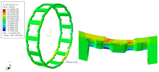
Figure 8.
Bearing cage surface stress.
Given the discrepancies between the material strength specified in DIN EN 10111:2008 and the actual measured values, the actual measured values of 558 and 577 MPa were used for verification in this case. The symmetrical fatigue limit σ−1 of the cage according to the empirical formula of material fatigue limit in the mechanical design manual was determined as follows:
Rp0.2 = 0.75Rm = 418.5–433 MPa
σ−1 = 0.23(Rm + Rp0.2) = 225–232 MPa
According to the calculation, the cage could generate a maximum tensile stress of 120 MPa at the stamping position during operation. In addition, discrete residual tensile stresses were identified at the same location, with a similar direction. The combined action of residual stress and tensile stress during operation led to the cage stress exceeding the material fatigue limit, thus resulting in a fatigue fracture.
3.7. Discussion on Corrective Measures
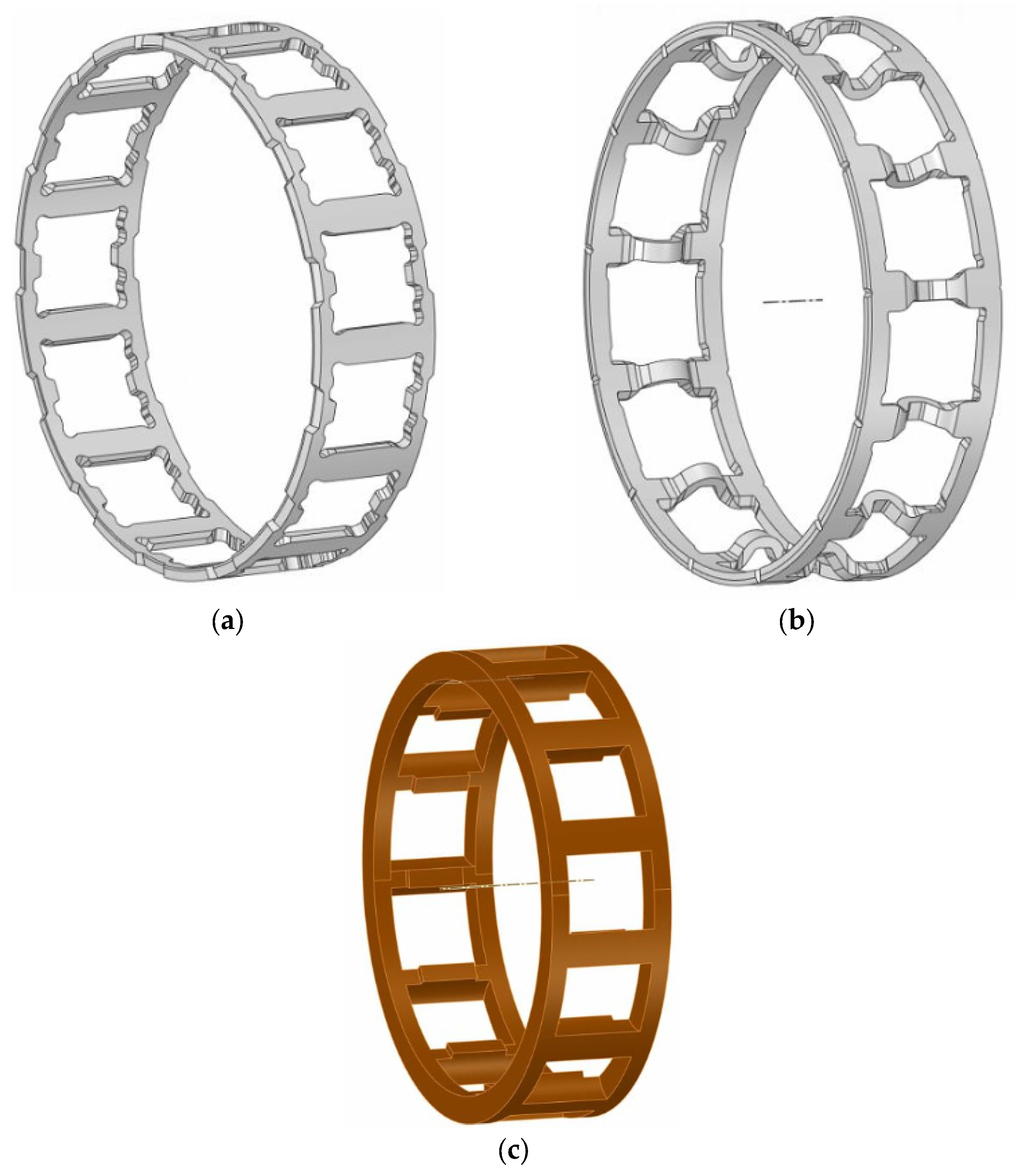
To solve the problem of the bearing cage fracture, SKF NU312 EC bearing cage types were investigated. The result indicated that SKF had modified the steel cage structure, as depicted in Figure 9a,b. In addition, nylon cages were found, as shown in Figure 9c.

Figure 9.
NU312 EC bearing cage structure. (a) Broken steel cage structure. (b) New steel cage structure. (c) Nylon cage structure.
In the calculation, the same design condition as that of the old cage (load: 725 N, rotational speed: 4657 r/min) was selected.
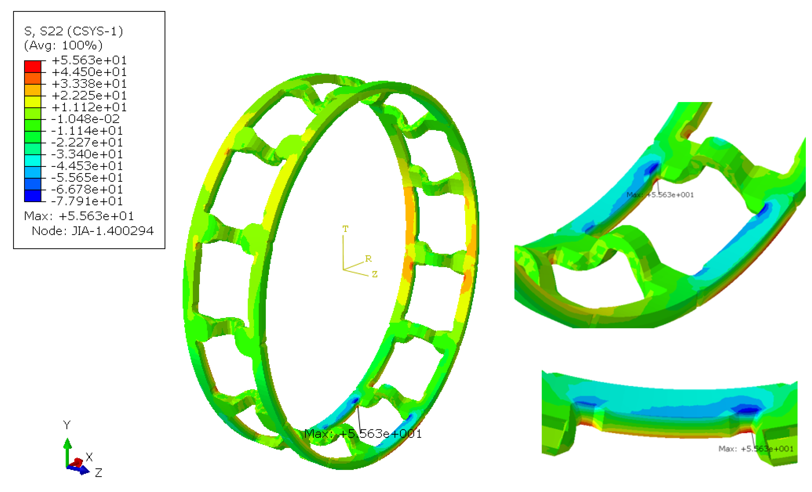
The force distribution on the new steel cage was calculated as shown in Figure 10. The stress of the new steel cage was concentrated at the chamfer of the front beam with a maximum tensile stress of only 55.6 MPa, which was much lower than the value (120 MPa) of the old one. In this respect, the new steel cage reduced the risk of fatigue fracture structurally.

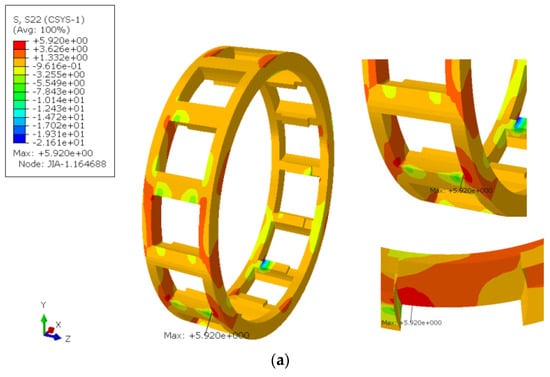
Figure 10.
Surface stress of the new steel cage structure.
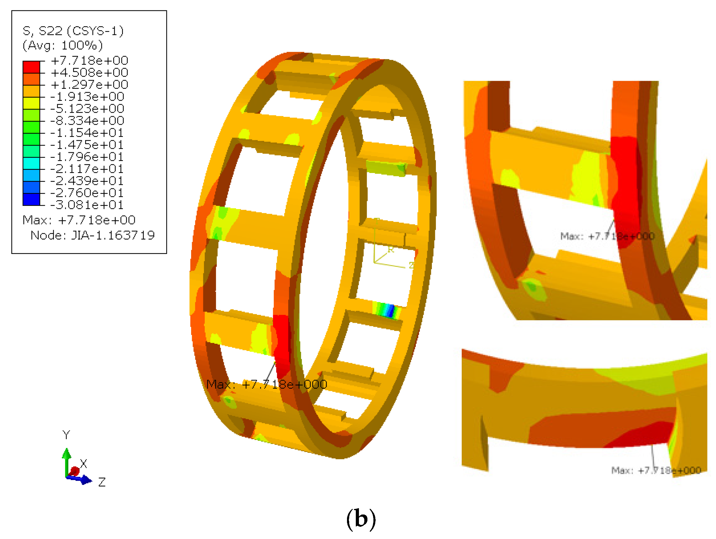
The force contribution of the nylon cage under two lubrication conditions (Table 5) was also calculated. Under the same operating conditions as those of the steel cage, the maximum tensile stress of the cage was at the corner of the front cross beam with a value of 5.9 MPa, as shown in Figure 11a. Increasing the bearing friction coefficient could increase the maximum tensile stress of the cage up to 7.7 MPa, which is still at a low level, as demonstrated in Figure 11b. Due to the tensile strength of PA66 being 75.46–83.3 MPa while its yield strength is 54.88 MPa, which is much higher than the calculation results above, it can be assumed that the nylon cage has a high safety margin.
Table 5.
Two selected working conditions for the force contribution calculation.

From the above studies, after the manufacturer changed the NU312EC steel cage structure, the stress concentration of the steel cage was significantly reduced. However, the residual stress was unknown. In addition, owing to its material and structural characteristics, the stress of the nylon cage was one order of magnitude lower than that of the new steel cage. According to the structure of the nylon cage, it should be integrally formed without machining residual stress. It had good self-lubricating characteristics, so its reliability was inferred to be higher. The nuclear power plant has been using this type of bearing for several months, and no obvious problems have been found.
4. Conclusions
This study conducted a comprehensive investigation and analysis of bearing cage fracture failure in a charging pump. By applying metallographic failure analysis methods, defects in the cage material, as well as the initial damages during transportation and installation, were observed. In addition, residual stresses at the stamped positions were measured. Finite element analysis was performed to calculate the working stresses experienced during bearing operation. The main conclusions are as follows:
- (1)
- The material of the bearing cage was carbon structural steel with the proper chemical composition, microstructure, and hardness.
- (2)
- The fracture of the bearing cage was located at the stamping depression position, which showed fatigue fracture mode.
- (3)
- The bearing cage had large residual stress at some stamping positions of up to 142 MPa. When the bearing was running, the working stress reached the maximum while the bearing roller entered and exited the working area. The direction of the residual stress was the same as that of the working stress, both of which were tensile stresses perpendicular to the fracture direction. The superposition of the two stresses exceeded the material fatigue limit.
- (4)
- The new structure could reduce the stress concentration of the steel cage, thus improving its reliability.
- (5)
- The nylon cage had the lowest stress concentration (without residual stress) and a good lubrication function, which further improved its reliability.
- (6)
- Both materials and structures should be considered simultaneously in the future design of bearing cages.
Author Contributions
Writing—original draft preparation, Q.C.; writing—review & editing, S.J.; supervision, D.D. All authors have read and agreed to the published version of the manuscript.
Funding
The research is funded by the Chief Research Grant for the KSB Charging Pump (RHM 100-205.12), with the project number: R-2021SZME04TF.
Data Availability Statement
Not applicable.
Acknowledgments
The authors gratefully acknowledge professor-level engineer Yinhui Che for his help in design of methodology, senior technician Chengrun Cai for his assistance of investigation, and engineer Jiazhu Cai for his efforts in data collection.
Conflicts of Interest
The authors declare no conflict of interest.
References
- Warda, B.; Chudzik, A. Effect of ring misalignment on the fatigue life of the radial cylindrical roller bearing. Int. J. Mech. Sci. 2016, 111–112, 1–11. [Google Scholar] [CrossRef]
- Salam, I.; Tauqir, A.; Haq, A.U.; Khan, A.Q. An air crash due to fatigue failure of a ball bearing. Eng. Fail. Anal. 1998, 5, 261–269. [Google Scholar] [CrossRef]
- Guo, H.; Duan, H.T.; Lei, J.Z.; Wang, D.F.; Du, S.M.; Zhang, Y.Z.; Ding, Z.Y. Failure analysis of automobile engine pump shaft bearing. Adv. Mech. Eng. 2021, 13, 1–9. [Google Scholar] [CrossRef]
- Oktaviana, L.; Tong, V.C.; Hong, S.W. Skidding analysis of angular contact ball bearing subjected to radial load and angular misalignment. J. Mech. Sci. Technol. 2019, 33, 837–845. [Google Scholar] [CrossRef]
- Yang, Z.C.; Zhang, Y.; Zhang, K.; Li, S.H. Wear analysis of angular contact ball bearing in multiple-bearing spindle system subjected to uncertain initial angular misalignment. J. Tribol. 2021, 143, 091703. [Google Scholar] [CrossRef]
- Huang, H.J.; Wang, X.; Xue, K.J. Effect of Cage Wear in Rolling Bearing on Bearing Failure. Lubr. Eng. 2021, 46, 128–136. [Google Scholar]
- Yang, Z.H.; Niu, X.L.; Li, C.H. Experimental Study on Cage Dynamic Behavior of Long-Life High-Precision Ball Bearing with Trajectory Deviation. IEEE Trans. Instrum. Meas. 2022, 71, 5011511. [Google Scholar] [CrossRef]
- Harris, T.A.; Kotzalas, M.N. Advanced Concepts of Bearing Technology: Rolling Bearing Analysis, 5th ed.; Taylor & Francis Group: Boca Raton, FL, USA, 2006. [Google Scholar]
- Crawford, T.S. The experimental determination of ball bearing cage stress. Wear 1970, 16, 43–52. [Google Scholar] [CrossRef]
- Liu, L.; Huo, S.; Zheng, K.; Wang, L.Q. Analysis of roller bearing cage broken under high DN value. J. Aerosp. Power 2020, 35, 2115–2122. [Google Scholar]
- Wang, P.F.; Yang, Y.; Ma, H.; Xu, H.Y.; Li, X.; Luo, Z.; Wen, B.C. Vibration characteristics of rotor-bearing system with angular misalignment and cage fracture: Simulation and experiment. Mech. Syst. Signal Process. 2023, 182, 109545. [Google Scholar] [CrossRef]
- Hinton, W.R. An investigation into the causes of ball bearing failures in types P2 and P3 engine-driven generators. Wear 1970, 16, 3–42. [Google Scholar] [CrossRef]
- Tauqir, A.; Salam, I.; Haq, A.U.; Khan, A.Q. Causes of fatigue failure in the main bearing of an aero-engine. Eng. Fail. Anal. 2000, 7, 127–144. [Google Scholar] [CrossRef]
- Wang, P.F.; Xu, H.Y.; Ma, H.; Han, H.Z.; Yang, Y. Effects of three types of bearing misalignments on dynamic characteristics of planetary gear set-rotor system. Mech. Syst. Signal Process. 2022, 169, 108736. [Google Scholar] [CrossRef]
- Wei, M.; Dyson, J.E.; Darvell, B.W. Failure analysis of the ball bearings of dental air turbine hand pieces. Aust. Dent. J. 2013, 58, 514–521. [Google Scholar] [CrossRef] [PubMed]
- Sakaguchi, T. Dynamic Analysis for Needle Roller Bearings Under Planetary Motion. NTN Tech. Rev. 2007, 75, 94–100. [Google Scholar]
- Nogi, T.; Maniwa, K.; Matsuoka, N. A dynamic analysis of cage instability in ball bearings. J. Tribo. 2018, 140, 88–96. [Google Scholar] [CrossRef]
- Deng, S.E.; Xie, P.F.; Yang, H.S.; Gao, Y.T. Flexible-body dynamics analysis on cage of high-speed angular contact ball bearing. Acta Armamentarii 2011, 32, 626–631. [Google Scholar]
- Feng, Y.J.; Yin, Y.F.; Zhao, C.J.; Zhang, J. Finite element analysis on dynamic characteristics of angular contact ball bearing cages. Bearing 2020, 6, 1–6. [Google Scholar]
- Brooks, J.; Canfield, R.A. Slotted Waveguide Stress Concentration Factor. AIAA J. 2022, 60, 3844–3851. [Google Scholar] [CrossRef]
- Sun, L.; Huang, X.P.; Huang, Y.C.; Wu, X.Y.; Wang, F. Experimental study on fatigue crack propagation in balcony opening corners of a cruise ship. Ocean Eng. 2022, 260, 112039. [Google Scholar] [CrossRef]
- Hou, X.; Diao, Q.; Liu, Y.; Liu, C.; Zhang, Z.; Tao, C. Failure Analysis of a Cylindrical Roller Bearing Caused by Excessive Tightening Axial Force. Machines 2022, 10, 322. [Google Scholar] [CrossRef]
- Zhu, C.F.; He, J.F.; Peng, J.F.; Ren, Y.P.; Liu, X.Z.; Zhu, M.H. Failure mechanism analysis on railway wheel shaft of power locomotive. Eng. Fail. Anal. 2019, 104, 25–38. [Google Scholar] [CrossRef]
- Fan, K.F.; Liu, D.X.; Zhang, X.H.; Liu, D.; Zhao, W.D.; Yang, J.; Ma, A.; Li, M.; Qi, Y.; Xiang, J.F.; et al. Effect of residual stress induced by ultrasonic surface rolling on fretting fatigue behaviors of Ti-6Al-4V alloy. Eng. Frac. Mech. 2022, 259, 108150. [Google Scholar] [CrossRef]
- DIN EN 10111: 2008; Continuously Hot Rolled Low Carbon Steel Sheet and Strip for Cold Forming—Technical Delivery Conditions. English Version; German Institute for Standardization: Berlin, Germany, 2008.
- Hou, X.Q.; Liu, Y.J.; Li, T.Y.; Liu, C.K.; Zhang, Z.; Tao, C.H. Root Cause Failure Analysis of Deep-Groove Ball Bearing Used in a Governor. Appl. Sci. 2022, 12, 9658. [Google Scholar] [CrossRef]
- Schlicht, H.; Vetters, H. Residual stresses in roller bearing components. Mater. Sci. Forum 2013, 768–769, 755–761. [Google Scholar] [CrossRef]
- Wang, H.; Wanchuck Woob, W.; Lee, S.Y.; An, G.; Kim, D.K. Correlation of localized residual stresses with ductile fracture toughness using in situ neutron diffraction and finite element modelling. Int. J. Mech. Sci. 2019, 160, 332–342. [Google Scholar] [CrossRef]
- Huang, Y.T.; Hung, F.Y.; Yen, C.W. Microstructure and fracture toughness of hot-rolling biomedical degradable ZKX500 magnesium bone plates. Micron 2023, 172, 103500. [Google Scholar] [CrossRef]
- Shoemaker, T.K.; Harris, Z.D.; Smudde, C.M.; Hill, M.R.; Burns, J.T. 3D fatigue crack path deflection and residual stresses in 17-4PH stainless steel rod. Int. J. Frac. 2023, 175, 107735. [Google Scholar] [CrossRef]
- Nguyen, T.T.; Pham, V.; Tran, H.A.; Nguyen, D.H.; Nguyen, T.H.; Dinh, H.B. Effect of Residual Stress on Mode-I Stress Intensity Factor: A Quantitative Evaluation and a Suggestion of an Estimating Equation. Metals 2023, 13, 1132. [Google Scholar] [CrossRef]
- Song, W.; Man, Z.; Xu, J.; Wang, X.X.; Liu, C.Q.; Zhou, G.T.; Berto, F. Fatigue Crack Growth Behavior of Different Zones in an Overmatched Welded Joint Made with D32 Marine Structural Steel. Metals 2023, 13, 535. [Google Scholar] [CrossRef]


Disclaimer/Publisher’s Note: The statements, opinions and data contained in all publications are solely those of the individual author(s) and contributor(s) and not of MDPI and/or the editor(s). MDPI and/or the editor(s) disclaim responsibility for any injury to people or property resulting from any ideas, methods, instructions or products referred to in the content. |
© 2023 by the authors. Licensee MDPI, Basel, Switzerland. This article is an open access article distributed under the terms and conditions of the Creative Commons Attribution (CC BY) license (https://creativecommons.org/licenses/by/4.0/).