Review

Effect of Process Parameters on Friction Stir Welded Joints between Dissimilar Aluminum Alloys: A Review

Department of Engineering, University of Messina, Contrada di Dio 1, 98166 Messina, Italy
*
Author to whom correspondence should be addressed.
Metals 2023, 13(7), 1176; https://doi.org/10.3390/met13071176
Submission received: 29 May 2023 / Revised: 20 June 2023 / Accepted: 22 June 2023 / Published: 24 June 2023
(This article belongs to the Section Welding and Joining)

Abstract

:
Friction Stir Welding is a suitable solid-state joining technology to connect dissimilar materials. To produce an effective joint, a phase of optimization is required which leads to the definition of process parameters such as pin geometry, tool rotational speed, rotation direction, welding speed, thickness of the sheets or tool tilt angle. The aim of this review is to present a complete and detailed frame of the main process parameters and their effect on the final performance of a friction stir welded joint in terms of mechanical properties and microstructure. Attention was focused in particular on the connection between different aluminum alloys. Moreover, the experimental results were correlated to the development and the applications of tools which can be effectively used in the design of the manufacturing process such as finite element analyses, artificial neural networks, and statistical studies. The review also aims to be a point of reference to identify the best combinations of process parameters based on the dissimilar aluminum to be joined.
Keywords:
FSW; joining; aluminum

1. Introduction

Aluminum alloys are classified into non-heat-treatable and heat-treatable alloys. The first group includes pure aluminum alloys (series 1xxx) and alloys with manganese (3xxx series), silicon (4xxx series), and magnesium (5xxx series) as primary alloying elements. The second group includes aluminum alloys with copper (2xxx series), magnesium and silicon (6xxx series) and zinc (7xxx series) as the main additives [1]. Recently, due to the possibility of exploiting the best properties of each series, the aluminum alloys have been widely combined in many industrial fields including automotive, aerospace, and shipbuilding industries [2,3,4,5,6,7,8,9].
In this context, the joining process is strategic to create a stable and effective connection [10]. Particularly, in all cases, solid-state and liquid-state welding are the primary technology [11,12]. Whereas liquid-state welding is characterized by significant drawbacks (i.e., formation of intermetallic compounds with a low plastic deformability that makes brittle the joint), solid-state welding is more suitable to join light-weight plate and sheet such as aluminum [13]. It includes the following technologies providing a direct metal-to-metal contact with adequate pressure to generate a performant joint without the production of intermetallic compounds: explosion welding and transition joints, magnetic pulse welding, roll bonding, friction stir welding (FSW), friction bit joining, and ultrasonic spot welding [14].
Among these technologies, friction stir welding is a sustainable and green solution in terms of energy consumption and environmental impact [15,16,17,18,19]. Moreover, it is characterized by a limited set of process parameters: tool rotational speed, welding speed, axial force, and tool tilt angle, which are the main parameters that are involved in production of high-strength joints [20,21] (see Figure 1).
Moreover, apart from the above-reported process parameters, some latest papers focused on unusual process conditions like pin eccentricity, which improves the material flow and grain refinement in the stir zone as well as enhances the toughness of the weld joint [22,23,24,25], and cooling rate that, in steels, enhances strength ductility and corrosion resistance [26,27,28].
This fact allows to experimentally determine the optimal combination to produce effective joints that can be used in several structural applications; i.e., Sabry et al. [29] study the friction stir welding between several 6061-T6 aluminum plates with a 2 mm thickness and a A365 high-pressure die-casted aluminum battery tray with different thicknesses. Mertinger at al. [30] study the corner stationary shoulder friction stir welding process between AA7050-T7451 and AA2024-T4 sheets for aerospace applications with the aim to replace approximately 500,000 rivets on an Airbus A350 plane.
The process works by using a rotating tool made of a hard material, such as tungsten carbide, to generate friction and heat between the tool and the workpieces. The heat softens the material and allows the tool to penetrate the surface. The tool then moves along the joint, stirring the softened material together and forming a solid bond.
FSW is particularly useful in joining aluminum and other non-ferrous metals. It can be used to join plates, sheets, and extrusions with a thickness ranging from 0.5 mm to several centimeters. The process can be automated, making it suitable for mass production. One of the main advantages of FSW is that it produces a joint with no porosity, solidification cracks, or other defects that can weaken the joint. This makes the process particularly useful in applications where the joint must be strong and reliable, such as in the aerospace industry. Additionally, FSW produces minimal distortion and reduces the need for post-welding treatments. Despite its advantages, FSW has some limitations. It is not suitable for joining materials that have a large difference in thickness or that have complex shapes. Additionally, the process can be slower than traditional welding methods, which can be a disadvantage in some applications.
Many studies conducted in the last fifteen years have studied the FSW of dissimilar Al alloy joints focusing on several aspects such as process optimization, effect of process parameters, microstructure, mechanical properties, and heat treatments [31,32,33,34,35]. The aim of this review is to present that the process parameters influence the properties of a friction stir welded joint between two dissimilar aluminum alloys. Particularly, the work is structured into two main sections:
  • First, each process parameter is investigated in terms of influence on the joint performances;
  • Then, the attention is focused on the tools used to predict or better investigate these effects such as finite element analyses, artificial neural networks, and statistical studies.

2. Effect of Process Parameters

Optimizing the process parameters of friction stir welding is significantly influenced by the complex thermal and mechanical interactions induced during the welding process [36]. In regard to this fact, it is not possible to identify a unique strategy to join two similar or dissimilar materials with this process. Consequently, there is a wide selection of literature that investigates the best combinations of parameters as a function of the materials to be joined.
Preliminarily, when the attention is focused on dissimilar materials and especially on the dissimilar aluminum, it is much needed to highlight the role played by the type of aluminum alloy (i.e., heat-treatable or non-heat-treatable) and the thickness considering that the large number of authors work with thin sheets.
The choice of aluminum alloy can significantly influence the welding process and the resulting weld properties.
Heat-treatable aluminum alloys, such as the 2xxx, 6xxx, and 7xxx series alloys, derive their strength from a precipitation hardening process. These alloys contain alloying elements like copper, magnesium, and zinc, which form strengthening precipitates during a specific heat treatment cycle. The high temperatures generated during FSW can partially or completely dissolve the strengthening precipitates in the heat-affected zone of heat-treatable alloys (see Figure 2).
This leads to a localized softening effect reducing the overall strength of the weld in this zone. The heat generated during FSW may also cause a redistribution of precipitates in the weld zone, affecting the mechanical properties. The extent of redistribution depends on factors like the alloy composition, welding parameters, and cooling rate. Heat-treatable alloys may require a subsequent post-weld heat treatment to restore the desired mechanical properties after FSW. This process involves a specific temperature and time cycle to re-precipitate the strengthening phases, thereby regaining the desired strength [37]. Moreover, FSW affects the microstructure and the electrochemical behavior of the different regions (HAZ, TMAZ, SZ) formed during the process, as observed by de Viveiros et al. [38].
Non-heat-treatable aluminum alloys, such as the 1xxx, 3xxx, and 5xxx series alloys, do not respond to precipitation hardening. They primarily gain strength through cold working or strain hardening. Non-heat-treatable alloys generally exhibit minimal softening effects in the heat-affected zone during FSW. Since their strength relies on cold working, the localized heating in FSW does not significantly affect their mechanical properties. FSW can induce grain refinement due to the severe plastic deformation imposed by the rotating tool, enhancing certain properties like tensile strength and fatigue resistance. Unlike heat-treatable alloys, non-heat-treatable alloys typically do not require post-weld heat treatment. The mechanical properties of the weld joint are largely retained without additional heat treatment [39].
When friction stir welding a joint between a heat-treatable aluminum alloy and a non-heat-treatable aluminum alloy, several factors can influence the behavior of the welded joint. Heat-treatable and non-heat-treatable alloys have different mechanical properties. The heat-treatable alloy typically has higher strength, while the non-heat-treatable alloy may have lower strength but better formability. This mechanical mismatch can affect the overall strength and performance of the welded joint due to the change in hardness is different for precipitation-hardened and solid-solution-hardened aluminum alloys [40]. The joint may exhibit variations in strength, ductility, and toughness, particularly at the interface between the two alloys. During FSW, the heat generated by the frictional forces and the mechanical mixing of the materials can promote the formation of intermetallic compounds at the joint interface. These intermetallics may have different mechanical properties than the base alloys, which can further influence the joint behavior. This phenomenon is inevitable during welding of dissimilar metals. The type, volume, and distribution of intermetallics can vary depending on the specific alloy combination and welding parameters used [41,42,43,44,45].
The welding process can induce microstructural changes in both the heat-affected zone and the weld zone. The extent of these changes depends on factors such as the alloy composition, welding parameters, and cooling rate. Differences in microstructure, such as grain size, phase distribution, and precipitate formation, between the heat-treatable and non-heat-treatable alloys can affect the joint’s mechanical properties, including strength, hardness, and corrosion resistance [37,46,47]. In heat-treatable aluminum alloys, the process of softening is linked to the dissolution of strengthening precipitates and the growth of grain size when subjected to welding-induced thermal cycles. The decrease in mechanical properties in these alloys can be partially alleviated by implementing subsequent aging treatments, whether natural or artificial [48,49,50,51,52,53,54,55]. On the other hand, in non-heat-treatable aluminum alloys, the softened region significantly compromises the tensile properties, hardness, and fatigue resistance of the welded joints. The primary mechanisms responsible for this softening are recovery and recrystallization [56,57,58]. Beygi et al. [59] study a dissimilar AA2024/AA7075 joint observing that, after tensile test, the fracture surface is characterized by large dimples and precipitates inside these dimples as indicative of the coarsening of the precipitates in AA2024 which is placed on the retreating side. The occurrence of this coarsening in the region leads to significant softening, resulting in the concentration of plastic strain in that area. However, two factors prevent this coarsening from happening in AA7075 placed on the advancing side. Firstly, AA7075 begins in an artificially heat-treated state known as T6, whereas AA2024 starts in a solution-treated state called T3. Secondly, the maximum temperature reached during the FSW process is lower in AA2024 compared to that of AA7075. FSW can introduce residual stresses in the welded joint due to thermal expansion and plastic deformation. The combination of dissimilar alloys can lead to differential thermal expansion and contraction, resulting in residual stress concentrations. Residual stresses can influence the joint’s distortion, crack susceptibility, and overall mechanical behavior [60,61].
Finally, the response of the dissimilar alloys to post-weld heat treatment may differ. Heat-treatable alloys often require specific heat treatment cycles to achieve the desired mechanical properties. However, the non-heat-treatable alloy may not respond to traditional heat treatments [62]. Consequently, careful consideration should be given to the selection and optimization of these processes for dissimilar aluminum alloy joints.
Also, the thickness of the sheets being welded in FSW can have a significant effect on the welding process and the resulting weld quality [63,64].
Thicker sheets require more heat input to raise their temperature to the desired range for FSW. The increased thickness implies a larger volume of material to be heated, which requires more time and energy. Consequently, thicker sheets may require adjustments in the welding parameters, such as increased rotational speed and downward force, to generate sufficient heat for effective stirring and plasticization of the material. Thicker sheets also have a higher propensity for heat dissipation due to their larger volume, resulting in a more significant temperature gradient across the thickness during FSW. This non-uniform temperature distribution can affect the metallurgical properties of the weld, including the formation of defects such as voids, cracks, or incomplete bonding. Proper control of process parameters, such as rotational speed, travel speed, and dwell time is crucial to ensure adequate heat input and minimize thermal gradients.
Thicker sheets may exhibit higher levels of residual stresses due to the larger thermal gradients and associated thermal expansion and contraction effects. These residual stresses can affect the structural integrity of the weld and may require post-weld heat treatment or other stress relief techniques to mitigate their influence [65].
The thickness of the sheets influences the material flow and mixing characteristics. Thicker sheets tend to exhibit slower material flow due to their higher thermal mass and increased resistance to deformation. This can result in variations in the mixing of material between the advancing and retreating sides of the weld. To compensate for this, optimized tool geometry and process parameters can be employed to promote better material mixing and achieve a homogeneous weld.
Thicker sheets generally offer increased joint strength in FSW due to the larger bonded area and more substantial material volume participating in the welding process. This is because the increased thickness provides more material for the stirring action of the rotating tool, resulting in enhanced mixing and bonding between the adjacent sheets. The larger bonded area and more substantial material volume contribute to the overall joint strength [66,67,68].
However, the increased thickness can also introduce challenges such as inadequate heat input, insufficient mixing, or defects if not properly addressed. To ensure high-quality welds, it is essential to optimize the process parameters, tool design, and post-weld inspections to account for the specific characteristics of thicker sheet materials.
The specific parameter adjustments in friction stir welding (FSW) for tool rotational speed, welding speed, and axial load as a function of sheet thickness can vary depending on the material being welded and other factors [69,70].

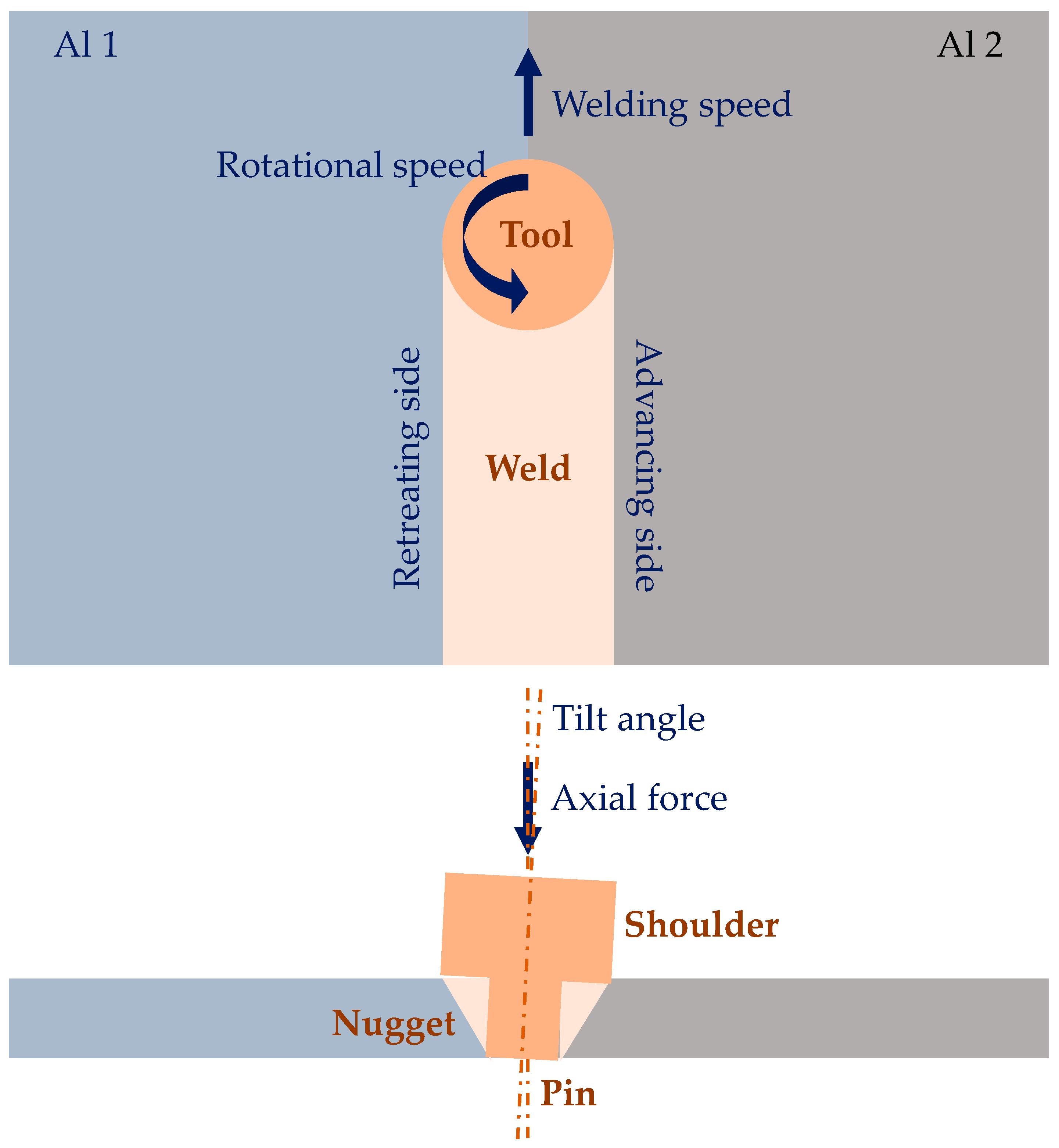
2.1. Tool Shoulder and Pin Geometry

The tool used in friction stir welding is typically made of a hard, wear-resistant material such as tungsten carbide, tool steel or ceramics. It has a cylindrical shape with a shoulder at one end and a pin at the other [71]. The shoulder is larger in diameter than the pin and is used to apply downward force to the workpieces and to contain the material being stirred during the welding process. The pin, which is the active part of the tool, has a specially designed profile that varies depending on the material being welded and the desired welding parameters. The pin profile typically includes a threaded or fluted section that helps to mix and stir the material being welded, as well as a smooth section that creates a solid-state bond between the workpieces. Table 1 reports the main geometries of bottom pin surfaces [72]. The tool is typically rotated at a high speed (the range of variation is typically between 280 [73] and 2500 [74,75] revolutions per minute) and is traversed along the joint line at a controlled rate. The rotation and movement of the tool generate heat through friction, softening the material and causing it to deform plastically. The softened materials are then stirred together by the tool, forming a solid-state weld without the need for filler material or fusion. The tool geometry in FSW is a critical factor in determining the quality, strength, and efficiency of the welding process [76]. In addition to various parameters, the shoulder diameter to pin diameter ratio impacts mechanical strength and grain refinement [77]. Consequently, the design and optimization of the tool geometry are important considerations in achieving successful and cost-effective FSW [78].
Generally, the size of the pin and shoulder of the tool determines the size of the stir zone, which is the area where the material is plastically deformed and mixed (i.e., a larger tool pin diameter produces a larger stir zone, while a larger shoulder diameter produces a wider heat-affected zone).
The shape and design of the tool pin and shoulder affect the direction and magnitude of material flow during the welding process [79,80]. The strength of the resulting weld joint is affected by the tool geometry, particularly the pin geometry. The shape and size of the tool pin affects the amount of plastic deformation and mixing that occurs during the welding process, which in turn affects the strength and quality of the resulting joint [81]. A pin with a threaded or fluted design can create a more efficient mixing of the material, while a flat or smooth pin produces less material mixing [82]. The tool geometry affects the amount of heat generated during the welding process. A larger tool shoulder diameter produces more heat due to the increased surface area of contact with the workpiece [83,84]. Finally, the geometry of the tool affects the rate of tool wear during the welding process. A tool with a more complex geometry may wear faster than a simpler tool, which can increase the cost of the process and reduce productivity [85].
Typical tool pin profiles are cylinder or straight cylinder, square, hexagonal, triangular, threaded cylinder, cylindrical cam, conical, taper, pentagonal, taper cylindrical tool, taper square tools [78]. Commonly, shoulder profiles employed are flat, concave, and convex (see Table 2 [86,87]). Additional features on the pin such as a spiral or a groove improve frictional behavior as well as material flow [14]. The material stirring and mixing are significantly influenced by the choice of pin profile.
Verma et al. [88] study the effect of tool pin profile on friction stir welded joints between dissimilar plates made of AA6061-T6 and AA5083-O. Amongst different types of tool pin profiles, the FSW tool with a straight cylindrical pin profile is characterized by maximum strength and elongation of the joint for different combinations of welding parameters. Furthermore, based on multiple response optimization, the authors determine that the welded joint created using the pin tilted at 1.11° and operating at a tool speed of 1568 rpm and a feed rate of 39.53 mm/min achieves the maximum ultimate tensile strength of 135.83 MPa and a tensile elongation of 4.35%. In their study, Palanivel et al. [89] examine the impact of different shoulder profiles on the combination of AA5083 and AA6351. Three shoulder features are utilized—partial impeller, full impeller, and flat grove. Results indicate that the full impeller shoulder tool is most effective in producing superior mechanical strength, attributed to its ability to generate enhanced material flow. Azmi et al. [90] investigate AA7075/AA5083 friction stir welded joints using three different pin profiles (i.e., threaded straight cylindrical, tapered cylindrical, and threaded tapered cylindrical) and three different tool rotational speeds (i.e., 600, 700, and 800 rpm) at a welding speed of 40 mm/min. The authors find that the tool pin profile is significant in determining mechanical properties by varying the rotational speed. The highest tensile strength and the defect free joint is obtained by using the threaded tapered cylindrical pin tool at a rotational speed of 800 rpm.
Dissimilar Al alloy combinations are joined using cylindrical or conical pin profiles which may feature threads or threads with flats by evidencing the way in which the pin profile significantly affects material stirring and mixing. Various pin profiles, such as cylindrical or conical shapes, with additional features like threads or threads with flats, are utilized for dissimilar aluminum alloy combinations. When the pin profile lacks threads, it offers a smaller surface area for material interaction. On the other hand, threaded and flat features on the pin increase the contact area, and the threads guide the material flow around the pin in both rotational and translational directions. Hasan et al. [91] investigate the effect of pin flute radius during the joining process of dissimilar AA7075-T651 and AA2024-T351 aluminum alloys. Particularly, they focus on five pin tools with different flute radii (i.e., 0, 2, 3, 6, and ∞ mm) under a specific combination of spindle speed and traverse rate (900 rpm/150 mm/min) by observing that a pin tool with a flute of radius equals to that of the pin leads to the strongest joint. Kalemba-Rec et al. [73] study two different types of tools for welding 7075-T651 and 5083-H111 alloys. Both tools have similar dimensions and consist of a spiral shoulder, but with different pin design, i.e., triflute or tapered with a thread. In particularly, a triflute pin guarantees the highest tensile strength and efficiency, as well as a defect-free joint with a wider area of the stir zone compared to the other kind of pin with 5083 on the advancing side and 7075 on the retreating side using a tool rotational speed of 280 rpm. Better mixing of materials is achieved at higher rotational speed; however, under these conditions, the weld microstructure shows more defects such as porosity, voids, or wormholes. Ilangovan et al. [92] investigate three 5.7 mm length pin profiles, namely straight cylindrical, threaded cylindrical, and tapered cylindrical profiles to fabricate AA5086-O (in retreating side) and AA6061-T6 (in advancing side) aluminum joints using a tool rotational speed of 1100 rpm, a welding speed of 22 mm/min and an axial force of 12 kN. The high-speed steel tool is characterized by a shoulder diameter of 18 mm and an inclination of 1 degree. The authors observe that (i) the straight cylindrical pin profile is not effective because it induces cross-sectional macro level defects in the stir zone; (ii) threaded and tapered cylindrical pin profiles guarantee defect-free joints with similar tensile properties; (iii) the threaded cylindrical pin profile is preferred due to the formation of finer and uniformly distributed precipitates, circular onion rings and smaller grain. It contributes to a better flow of materials between the two alloys and the generation of defect-free stir zone. Additionally, this configuration yields elevated hardness values, measuring 83 HV in the stir zone, as well as a higher tensile strength of 169 MPa compared to the other two profiles. The enhanced hardness is primarily attributed to the formation of fine grains and intermetallics within the stir zone. Furthermore, the reduced size of weaker regions, such as the thermomechanical affected zone and the heat-affected zone, contributes to the overall improvement in tensile properties. In the welding of 5052-H32 (in advancing side) and 6061-T6 (in retreating side) aluminum alloys, this behavior changes. In fact, Balamurugan et al. [93] find that using a M2 HSS tool characterized by a pin height of 4.7 mm and a shoulder diameter of 18 mm with two different pin profiles (i.e., taper cylinder and threaded cylinder) under constant welding speed and tool rotation speed of 60 mm/min and 900 rpm, respectively, generates a joint characterized by better tensile strength, larger nugget area, and smoother surface finish. However, the taper pin profile leads to such a fine grain microstructure that the connection results strong [93].
Recrystallization is a process by which the microstructure of a metal is transformed from a deformed, or strained, state to a more relaxed, or strain-free, state. During FSW, the high temperatures generated by the frictional heat of the rotating tool cause the microstructure of the metal to become deformed and strained. As the tool moves along the joint line, it creates a region of heat-affected zone on either side of the weld. Within this zone, the metal experiences a range of temperatures, from below its recrystallization temperature to well above it. As the tool passes through the metal, it causes the grains to deform and align themselves in the direction of the tool rotation. However, as the metal cools, the grains attempt to revert to their original, strain-free state. This causes the grains to recrystallize and grow, with the new grains becoming oriented in a more relaxed, strain-free manner. The recrystallized grains help to reduce the residual stresses that are present in the weld, leading to a stronger and more ductile joint. Overall, the recrystallization phenomenon in FSW is an important aspect of the process that helps to ensure a high-quality weld. By reducing residual stresses and improving the ductility of the joint, recrystallization can help to improve the mechanical properties of the welded components and ensure that they are able to withstand the stresses and strains of their intended application [94,95].
The tool pin profile plays an important role in determining the extent of recrystallization that occurs during friction stir welding (FSW). The shape, size, and geometry of the tool pin can affect the temperature distribution, strain distribution, and shear deformation in the material during the welding process, which in turn can affect the degree of recrystallization that occurs. A tool pin with a larger diameter and a more rounded profile generates more heat and causes more material flow during FSW, leading to a greater degree of recrystallization [92,93,96,97]. This is because the larger pin produces more frictional heat, leading to a higher temperature in the material, and the more rounded profile results in a greater degree of material flow, causing more grains to be deformed and realigned. Conversely, a tool pin with a smaller diameter and a more angular profile generates less heat and causes less material flow, resulting in a lower degree of recrystallization. This is because the smaller pin produces less frictional heat, leading to a lower temperature in the material, and the more angular profile results in less material flow, causing fewer grains to be deformed and realigned [92,93]. In addition to the size and shape of the tool pin, the pin material can also affect the degree of recrystallization. A tool pin made of a material with a lower thermal conductivity, such as tungsten or molybdenum, can generate more heat during FSW, leading to a higher degree of recrystallization. On the other hand, a tool pin made of a material with a higher thermal conductivity such as copper can dissipate heat more quickly, leading to a lower degree of recrystallization. Consequently, this profile alone is not a factor that can influence the grain of the microstructure, and this can lead to different behaviors as observed between [92,93].
Studies on polygonal pin profiles evidence a significant pulsating effect in the dissimilar joints during the material stirring and mixing, leading to the adhesion between material and pin geometry enhancing the flow of plasticized metal under the tool shoulder in the stir zone [98]. In regard to this fact, the more suitable pins are cylindrical or conical [14]. Tiwan et al. [99] study the microstructural and mechanical properties of dissimilar joints between AA2024-O and AA6061-T6 at varying tool rotation speeds (i.e., 900, 1400, 1800 rpm) by observing that the pin geometry affects the size of the stir zone. Particularly, a tool with a cylindrical profile at the tool rotation speed of 1400 rpm is more suitable because it allows the lower sheet material around the pin to flow upward during welding without any retardation in contrast to a stepped pin. Consequently, simplicity is preferable to complexity.
When dissimilar materials are joined, polygonal pin profiles can generate several defects such as voids, tunnel, cracks, and fragmental defects [100], such as evidenced in Figure 3. Palani et al. [101] investigate the influence of the pin profiles (i.e., square, pentagon and hexagon) on microstructure and tensile strength of dissimilar AA8011 and AA6061-T6 aluminum alloys. The authors determine that the more effective joints are found for hexagonal tool pin profile at a rotational speed of 1500 rpm, a plunge depth of 2.5 mm, and a welding speed of 40 mm/min.
In advancing side AA6061-T6 to the retreating side AA7075-T651 friction stir welded joints, Raturi et al. [102] investigate four different pin profiles, namely cylindrical, cylindrical tapered, cylindrical threaded with three flat faces, and truncated square pyramidal-shaped profile, hereafter referred to as trapezoidal tapered, by changing both the rotational speed (i.e., 660, 900, 1200, 1700 rpm) and the feed rate (i.e., 36, 63, 98, 132 mm/min). They observe that the cylindrical threaded with three flat faces tool pin and the cylindrical grooved tool pin with suitable intermediate tool rotation and feed rate lead to good tensile and flexural strength. The quality of friction stir welded joints, as well as the tensile strength and flexural load of the welds, are predominantly influenced by two factors: tool pin profiles and tool rotational speed. Excessively high rotational speed can lead to inferior nugget shape and inadequate joining of dissimilar metals. This is caused by the generation of excessive heat, which results in intense material softening. Consequently, poor friction, slipping, insufficient material delivery, and ultimately weak joint strength may occur. Similarly, a high feed rate can also result in reduced strength of dissimilar friction stir welded joints. An examination of the fracture surface reveals that joints prepared with appropriate tool pin profiles and process parameters exhibit ductile failure, as evidenced by the presence of micro voids and dimples in the well-bonded region. However, in contrast, some joints prepared with very high tool rotational speeds exhibit tearing, rupture, and brittle failure. On the same dissimilar joints, Raturi and Bhattacharya [103] study the wear phenomenon using a right-hand threaded with three intermittent flat faces tool pin at a 900 rpm tool rotation and a 98 mm/min welding speed.
The decrease in the mechanical performance from a simple pin profile (i.e., triangular) to a complex pin profile (i.e., hexagonal) occurs due to the decrease in traverse force and the enhanced structural stiffness with an increase in the number of pin sides and the resulting reduction in the bending moment and shear force [104]. Yuvaraj et al. [105] investigate simple HSS tool pin profiles (i.e., square, cylindrical, and triangle) in the welding of AA7075-T651 and AA6061 aluminum plates by finding that the best joints result in a square profile tool pin with a tool offset of 0.9 mm and a tool tilt angle of 2 degrees. In this case, the joint exhibits fine grains along the stir zone due to adequate heat generation. Furthermore, the triangular pin reveals granular grain structure due to an additional heat generation and a consequent turbulent flow of material. Krishna et al. [106] investigate three pin profiles (i.e., straight cylinder, straight square and tapered hexagon) on Al 6061 and Al 7075 joints. The authors find that, by using the straight cylinder tool pin profile with a rotational speed of 950 rpm, a welding speed of 60 mm/min and 6061 in the advancing side, it is possible to obtain higher mechanical properties due to the geometrical configuration of the tool pin that does not show sharp edges, also providing smooth and perfect welding (see Figure 4). The other configurations, characterized by a sharp edge, do not lead to efficient and smooth welding.
El-Hafez and El-Megharbel [107] weld dissimilar aluminum alloys AA2024-T365 and AA5083-H111 by using square, triangular, and stepped profiles. They find that the square pin produces the best strength coupled with a welding speed of 16 mm/min and a rotational speed of 900 rpm due to the pulsed action (four pulses per revolution) that produces a good metal flow and, consequently, a good stirring, in agreement with [108,109]. Shine and Jayakumar [97] perform dissimilar FSW between AA5083-H111 and AA6061-T6 aluminum alloy by using three pin profiles (i.e., straight square, threaded cylinder, and tapered cylinder). From the experimental results, they observe that the straight square pin profile shows greater hardness values in the weld nugget zone and higher tensile strength in comparison to the others.
Table 3 summarizes these experimental results.

2.2. Tool Tilt Angle

The tilt angle refers to the angle between the FSW tool axis and the workpiece surface. It is an important process parameter that can affect the quality and properties of the welded joint [112,113].
The tilt angle can be adjusted during the FSW process to control the heat input (i.e., Figure 5) and material flow. Generally, a larger tilt angle results in a higher heat input and more material flow, which can lead to better mixing and homogenization of the welded material. This can result in a more uniform grain structure, improved mechanical properties, and increased joint strength. Moreover, a larger tilt angle can be useful for welding thicker materials or for achieving a desired weld shape. However, if the tilt angle is too large, it can cause defects such as tunneling and hooking, which can weaken the joint [114]. In addition, a larger tilt angle can also increase the likelihood of thermal distortion and residual stresses in the welded joint. Conversely, a smaller tilt angle can result in a lower heat input and less material flow, which can reduce the risk of defects and thermal distortion. However, if the tilt angle is too small, it can also cause defects such as hooking, as mentioned earlier. Di Bella et al. [115] investigate dissimilar aluminum alloys used in shipbuilding (AA6082 and AA5083) joined using a taper threaded pin profile at the following rpm/mm/min combinations: 1000/100, 1300/75 and 1600/50. The authors find that a small spindle inclination is sufficient to significantly improve the behavior of the joint by influencing the same effectiveness of the process.
Yuvaraj et al. [105] optimize the tool tilt angle in AA7075-T651/AA6061 joints by investigating the following values: 2, 3 and 4 degrees. Applying a statistical technique, the authors observe that the tool tilt angle is the primary governing factor influencing the friction stir welded dissimilar joint tensile strength. When the tool tilt angle increases, the gap expands between the work piece and tool [116]. In particular, the square profile tool pin and a great tilt angle of tool (i.e., 3 degrees) improve the mechanical properties of the joint of the weld joint.
It is worth noticing that FSW tool shoulders can also contain features to increase the amount of material deformation produced by the shoulder, resulting in increased workpiece mixing and higher-quality friction stir welds. These features can consist of scrolls, ridges or knurling, grooves, and concentric circles and can be machined onto any tool shoulder profile. Scrolls are the most observed shoulder feature. The channels direct deformed material from the edge of the shoulder to the pin, thus eliminating the need to tilt the tool [117]. Such tools are particularly preferred for curved joints [117,118].

2.3. Tool Rotational Speed

The tool rotational speed represents the speed at which the welding tool rotates as it moves along the joint between the two pieces of metal being welded. During the FSW process, the rotating tool generates heat and friction, which softens the metal and creates a plasticized region around the tool. The tool then moves along the joint, pushing the softened metal behind it to create a solid-state weld.
It is a critical parameter in FSW, and it has several effects on the welding process [119,120] by influencing the following:
  • Heat generation: as the tool rotates, it generates frictional heat due to the contact between the tool and the workpiece, controlling heat generation or heat input as they relate to the material plastic flow [31]. Higher rotational speeds result in more heat generation, which can cause the material to soften and lead to better mixing and bonding between the two workpieces.
  • Plasticized zone size around the tool: it affects the intensity of plastic deformation and through this influences material mixing [31,73]. Moreover, a higher rotational speed can lead to a larger plasticized zone, which can result in a better bond between the two workpieces [121,122,123].
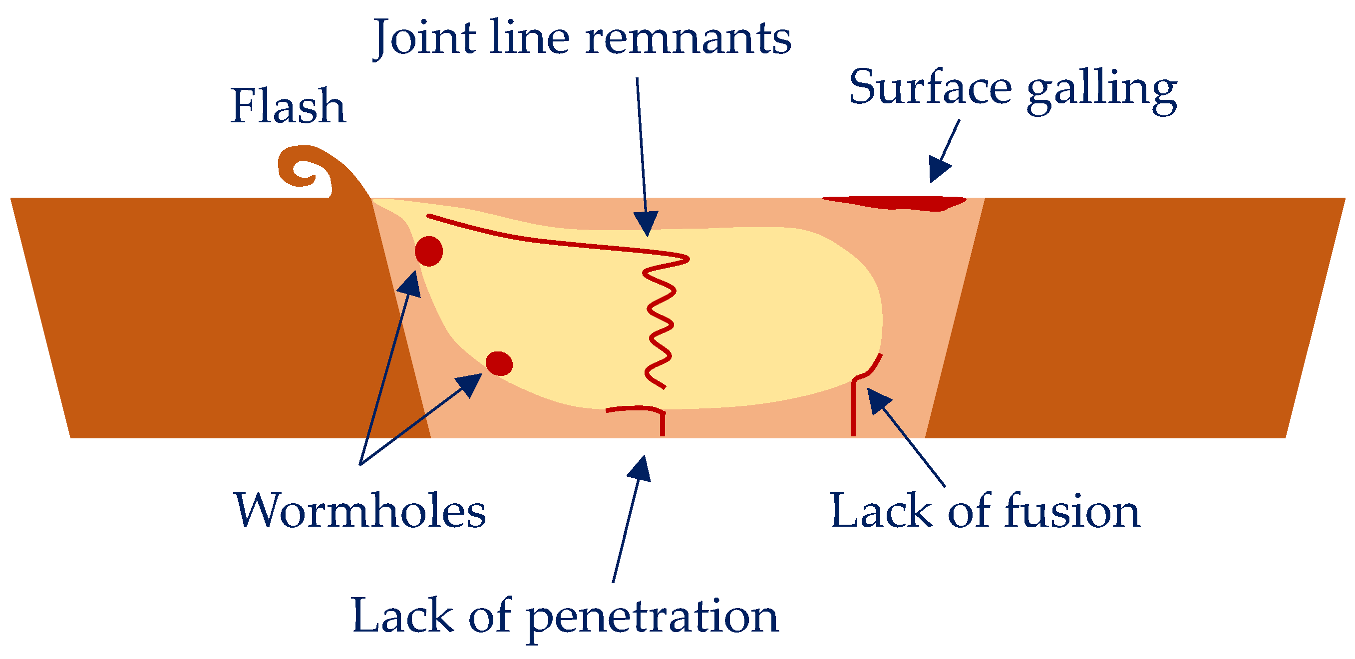
  • Weld quality: an exceedingly low rotational speed can result in incomplete weld formation and poor bonding between the two workpieces. On the other hand, if the rotational speed is too high, it can lead to defects in the weld, such as poor surface (flash), voids, porosity, and tunneling or formation of wormholes because of the excessive heat input.
  • Tool wear: higher rotational speeds can lead to more wear on the tool, which can reduce its lifespan.
  • Welding force (i.e., required to push the tool through the workpiece): the rotational speed of the tool can also affect the force. Higher rotational speeds generally require higher forces to maintain the tool’s position and prevent it from slipping out of the joint.
Moreover, this parameter affects the joint behavior as a function of the sheet aluminum alloy in different ways [124]. Changing the tool rotation rate influences the size and macrostructure of weld nugget zone in a friction stir welded AA2524-T351 aluminum alloy. The width of this zone increases with increase in the tool rotation rate. As the tool rotates at a high speed, the area of the recrystallized zone expands with increasing temperature, leading to this phenomenon [125]. Generally, insufficient energy is provided for dynamic recrystallization at lower rotational speeds, resulting in incomplete dynamic recrystallization and ineffective grain refinement strengthening. At higher rotational speed, the higher strength in weld nugget zone is attributed to smaller grain size [126]. In the weld of the AA5086-H32 alloy, lower rotational speed produces various defects due to the production of inadequate heat resulting in improper softening of the material [127]. The excessive heating and deformation caused by tool rotation in AA5052-O lead to an increase in b-phase (Mg2Al3) particles through magnesium atom diffusion towards grain boundaries. The dissolution of these intermetallic particles within the weld nugget zone subsequently results in reduced joint strength [128]. As the rotational speed of the FSW tool increases for the 6082-T6 aluminum alloy, the weld temperature first rises and then falls, leading to the formation of smaller equiaxed recrystallized grains in the nugget zone. Moreover, the hardness of the nugget zone increases as the rotational speed is raised to 1200 rpm due to the enhanced dislocation density. This increase in dislocations is attributed to the precipitation and dissolution of the second phase as well as the refinement of the aluminum matrix grain size in the microstructure of the zone [129]. For friction stir-welded 7075-T6 Al alloys, there exists a strong relation between rotational speed and weld properties, i.e., rise of the rotating speed from 600 to 1550 rpm increases the average nugget grain size from 6.8 to 8.9 mm. Also, at a medium rotating speed, the optimum mechanical properties are achieved [130].
Several studies on FSW involve dissimilar aluminum alloys [31,131]. Ghaffarpour et al. [132] join dissimilar aluminum alloys of 5083-H12 in the retreating side and 6061-T6 in the advancing side, changing the rotational speed (i.e., 700, 1600, 2500 rpm) in combination, respectively, with the pin diameter (i.e., 2, 3, 4 mm), the shoulder diameter (i.e., 10, 12, 14 mm), and the traverse speed (i.e., 25, 212.5, 400 mm/min). The authors find that the effect of the pin diameter is not as pronounced as the effect of the rotational speed. As the rotational speed and pin diameter increase, the input heat increases, resulting in higher tensile strength. Moreover, the effect of the rotational speed is more significant compared to the effect of the traverse speed and the shoulder diameter. Thermocouple measurements, tool torque, extent of material mixing, and macrostructural observations all indicate that the temperature under the tool is more strongly dependent on the rotation than the traverse speed as observed also in AA5083-AA6082 joints [133]. The increase in tensile strength with greater friction heat can be attributed to the improved mixing of dissimilar alloys due to proper stirring resulting from the higher heat input. Additionally, the plasticization effect during FSW is enhanced at higher heat inputs. Consequently, softer materials are easier to mix and stir. Nevertheless, the strength exhibits a maximum value with an increase in heat input, implying that further increments in heat generation lead to a reduction in strength beyond a certain optimum heat level. The lowest hardness is recorded in the heat affected zone of the AA6061-T6 sheet. It is also observed that when the tool rotational speed increases, the hardness of the mixing zone reduces. This can be explained in the following ways. Firstly, the higher rotational speed generates more heat, leading to local annealing in both sheets. Secondly, the frictional heat increases the temperature above the aging temperature of the 6061-T6 sheet. Consequently, the fine Mg2Si precipitates, which serves as the hardening phase in AA6061, either dissolving or growing, leading to a decrease in hardness. This same phenomenon can occur in 5083-H12 as well. Furthermore, excessive heat can cause grain growth in both alloys, thereby contributing to a decrease strength and hardness. Consequently, the optimal rotational speed takes intermediate values [134]. Palanivel et al. [135] produce AA5083-H111 (in the retreating side)/AA6351-T6 (in the advancing side) joints using three different tool rotational speeds (i.e., 600 rpm, 950 rpm and 1300 rpm) and five different tool pin profiles (i.e., straight square, straight hexagon, straight octagon, tapered square, and tapered octagon) with a constant welding speed of 60 mm/min, an axial force of 8 kN and a tilt angle of 0 degrees. The high-carbon high-chromium steel tool is characterized by a shoulder diameter of 18 mm, a pin diameter of 6 mm and a pin length of 5.7 mm. The two parameters affect the strength due to variations in material flow behavior, loss of cold work in the AA5083 heat-affected zone, dissolution and AA6351 over-aging of precipitates and formation of macroscopic defects in the weld zone. The best friction stir welded joint is obtained for a tool rotational speed of 950 rpm and a straight square pin profile. Mastanaiah et al. [121] study the effect of process parameters on dissimilar friction stir welds in AA2219-T6/AA5083 aluminum alloys, placing 5083 in the advancing side. In particular, the authors investigate five levels of rotational speed (i.e., 400, 800, 1200, 1600, 2000 rpm), welding speed (30, 210, 390, 570, 750 mm/min), and tool offset (−2, −1, 0, +1, +2 mm) using an H13-grade tool steel tool with a 15 mm diameter shoulder, a frustum-shaped threaded pin of a 6 mm top diameter and a 4 mm bottom diameter and a tilt angle of 2 degrees. Welds free of defects can be achieved under a wide range of conditions. However, it is important to note that when performing welds at the lowest rotation speed, highest traverse speed, and with a tool offset towards the AA2219 alloy side, defective welds may occur. The degree of intermixing is determined by the tool rotation speed and traverse speed. It is possible to observe that at higher tool rotation speeds and lower tool traverse speeds, there is a greater degree of intimate mixing between dissimilar alloys. Laska et al. [131] produce dissimilar butt joints from two alloys, AA5083 in the advancing side and AA6060 in the retreating side, by changing the rotational speed from 800 to 1200 rpm with a constant welding speed of 100 m/min and a tilt angle of 2 degrees. The tool shoulder has a flat surface with a diameter of 18 mm. The pin length measures 2.5 mm. The pin itself has a hexagonal shape with a distance across the flats of 6 mm. The pin is made of a 73MoV52 steel, while the shoulder is composed of a X210Cr12 steel. The findings demonstrate that an increase in tool speed leads to an increase in hardness within the weld nugget zone. This is attributed to the higher heat input and more efficient recrystallization process. The weld with the highest tool rotational speed (see Figure 6) exhibits the highest hardness in the nugget zone. Goriparthi et al. [136], in a comparative study between TIG welding and FSW, investigate dissimilar AA5083-O and AA7075-T651 aluminum alloys at different rotational speeds (i.e., 800, 1000, 1100, 1200, and 1400 rpm) and a welding speed of 40 mm/min, with a tool characterized by a straight square pin profile. They observe that at lower rotational speed, the generated heat is not sufficient, and at higher tool rotational speeds, excessive heat causes the overflow of solidified materials and defect formation. Devaraju et al. [137] study dissimilar 2024/6061 aluminum alloys using a tool with a shoulder diameter of 24 mm, a pin diameter of 8 mm, a pin length of 5.8 mm and a tilt angle of 1.5 degrees. The authors investigate three different rotational speeds (i.e., 900, 1120, and 1400 rpm) at a welding speed of 40 mm/min and an axial force of 5 kN. The presence of a well-defined grain boundary region distinguishes the recrystallized area known as the stirring zone from the distorted regions within the thermo-mechanically affected zone. Improved tensile properties are evident at a rotational speed of 900 rpm.
Conversely, the rise of the heat input decreases the hardness of the heat-affected zone, where recrystallization does not occur. In the heat-affected zone on the AA6060 side, the lowest density of dislocations with the highest mobility is observed, contributing to a reduction in strength within this zone. Das and Toppo [138] investigate three different tool rotational speeds (i.e., 900, 1100 and 1300 rpm) for producing AA6101-T6 (in advancing side)/AA6351-T6 (in retreating side) joints using a high-carbon and high-chromium steel taper cylindrical thread pin with a tilt angle of 2 degrees and a welding speed of 16 mm/min. The tool has a shoulder diameter of 25 mm, a big pin diameter of 8 mm, a small pin diameter of 6 mm and a pin length of 11.7 mm. In Charpy impact tests, it is observed that the minimum energy occurs at 900 rpm. This phenomenon can be attributed to the low friction pressure and insufficient friction time, which result in inadequate generation of frictional heat and insufficient time for the formation of a strong bond between the two dissimilar metals. However, as the rotational speed rises to 1100 rpm, the impact energy of the joint also increases. Subsequently, as the rotational speed further escalates to 1300 rpm, the impact energy decreases. This decline in impact energy could be attributed to grain refinement taking place in the weld zone due to the high heat generated.
Das et al. [139] analyze other mechanical properties of these two alloys, changing the rotational speed from 900 rpm to 1500 rpm and altering the axial force (i.e., 4, 5, 6, 8 kN) with a constant welding speed of 60 mm/min and using an EN32 steel tool with a cylindrical threaded pin profile displaying a tool tilt angle of 2 degrees. The flat-faced shoulder diameter, pin diameter and tool pin length are 18 mm, 6 mm, and 5.85 mm, respectively. The authors find that the rotational speed of 1300 rpm produces better mechanical and metallurgical properties joints. At lower rotational speeds, the tensile strength tends to be poor primarily because the tool stirring action is inadequate. This insufficient stirring leads to the generation of minimal frictional heat at rotational speeds of 900 rpm and 1100 rpm. Consequently, the material flow is compromised, resulting in lower tensile strength. However, an increase in rotational speed (1300 rpm) leads to an improvement in ultimate tensile strength. This occurs because the heat input at this speed is sufficient, promoting better weld quality. The weld region exhibits equiaxed fine grains, further enhancing tensile strength. Nevertheless, when the rotational speed exceeds a certain threshold (1500 rpm), excessive heat input becomes a factor. This excess heat input causes reprecipitation and reduces the dislocation density of strengthening precipitates such as Mg2Si. As a result, tensile strength is lowered. In bending tests, when the rotational speed is set to 900 rpm, the joints demonstrate lower ductility. Additionally, micro cracks can be observed on the outer surface of the weld joint. These issues arise due to improper mixing of the metals and insufficient downward force applied during the process. At 1100 rpm, there is an increase in heat generation, resulting in an improved flow of the softened mixed material comprising the two alloys. Consequently, the ductility of the joints improves. At a high rotational speed of 1500 rpm, the material flow becomes excessive due to the intense heat generated between the tool shoulder and the workpiece interface. This excessive flow causes the intermetallic compound Mg2Si to break, leading to a decrease in bending strength. However, when the rotational speed is set to 1300 rpm, the joint exhibits good ductility. This is attributed to the uniform interdiffusion of the intermetallic compound Mg2Si in the weld nugget region. As a result, the friction stir welded (FSW) joints demonstrate enhanced bending strength. Micro hardness tests reveal variations in hardness at the nugget region. These variations occur due to differences in heat input during the FSW process, which also impact the microstructures of the base alloy. At 900 rpm, the hardness is generally lower compared to that of the base alloys and other joints. This can be attributed to a softening effect that occurs at the weld joints. The hardness is dependent on the distribution of the intermetallic compound Mg2Si and the grain microstructure within the nugget region. At a rotational speed of 1300 rpm, the rate of heat input increases. This leads to the formation of fine equiaxed grains and a well-spaced microstructure within the weld nugget region. As a result, the weld nugget region exhibits an optimum micro hardness value. This indicates that the hardness at the nugget region is influenced by the grain size. However, as the rotational speed further increases to 1500 rpm, there is a decrease in hardness. This occurs primarily due to the high heat input, which leads to softening in the nugget region. Consequently, there is a reduction in grain size and the dissolution of strengthening precipitates, such as Mg2Si, further contributing to the drop in hardness. Aval [140] conducts a study on the impact of rotational speed on residual stress in dissimilar welded aluminum plates of two alloys, 6082-T6 in the advancing side and 7075-T6 in the retreating side, using an H13 steel tool with a shoulder of 23 mm in diameter, a triangular frustum pin, and a tilt angle of 2 degrees. During the experiments, various tool rotational speeds are tested, including 800, 1000, 1200, and 1400 rpm. Additionally, welding speeds of 90, 120, and 150 mm/min are used. However, only the welds created using rotational speeds of 1000 and 1200 rpm with welding speeds of 90 and 120 mm/min yield satisfactory results. The findings of the author reveal that as the rotational speed increases (from 1000 to 1200 rpm) and the traverse speed decreases (from 120 to 90 mm/min), both factors contribute to the processes of increased heat generation, higher peak temperatures, and reduced maximum tensile residual stress. Interestingly, these results contradict the findings of Giorgi et al. [141]. To explain these contradictory results, Richards et al. [142] propose that the stress profile observed in friction stir welding (FSW) is a result of the mismatch in plastic strains induced by steep temperature gradients during the welding process. As heat is generated by the FSW operation and distributed within the component while the tool advances, these plastic strains occur. Therefore, it can be inferred that peak temperatures alone do not solely determine the maximum tensile residual stress. Instead, the temperature gradient, particularly the material cooling rate and its uniformity, exert a more significant influence on the maximum tensile residual stress. These conclusions are supported by the findings of Campanelli et al. [143], who conducted an analysis on the effects of preheating the weld zone using a high-powered laser. Haribalaji et al. [144] investigate the FSW of two aluminum alloys, AA2014 in the advancing side and AA7075 in the retreating side. The process parameters are 1000, 1200, and 1400 rpm of rotational speed, 30, 45, and 60 mm/min of welding speed, 3, 6, and 9 kN of axial force, three different tool pin profiles (i.e., straight cylinder, tapered, and threaded pin) and a tilt angle of 0, 1, and 2 degrees. The tool, constructed from high-carbon steel H13, has a shoulder diameter of 20 mm and a pin diameter of 6 mm. The authors observe that rotational speed and axial force are significant factors in tensile strength and microhardness. Setting them correctly can prevent the formation of defect-free welds. The best welding parameters for achieving maximum tensile strength are a rotation speed of 1000 rpm, a welding speed of 45 mm/min, an axial force of 6 kN, and a tilt angle of 2 degrees. On the other hand, for achieving maximum hardness, the optimal parameters are a rotation speed of 1000 rpm, a welding speed of 60 mm/min, an axial force of 6 kN, and a tilt angle of 2 degrees. These optimal parameters are obtained by utilizing a threaded tool pin profile. Zuiko et al. [145] investigate two combinations of rotational and welding speed (500 rpm/380 mm/min and 1000 rpm/760 mm/min) on the AA5182/AA2519 joint placing the two sheets on the retreating side and advancing side, respectively. The welding tool consists of a shoulder of 12.5 mm in diameter and a cylindrical pin of 2.7 mm in length. For both combinations, defect-free welds are obtained. The first combination allows to obtain a slightly higher ultimate tensile strength in tensile tests. Tarkono et al. [146] investigate the quality of dissimilar aluminum alloys AA1100 and AA5052 by varying the rotational speed (i.e., 1750, 2230, and 3500 rpm, with a welding rate of 22 mm/min). They find that a speed of 1750 rpm induces defect of the hole, rough surface, and no stable welding, a speed of 2230 rpm induces rough surface but more stable welding, and a speed of 3500 rpm induces smooth surface and stable welding. Sivaselvan et al. [147] study friction stir welding joints between AA6061 and AA5083 by varying both the rotational (i.e., 1100, 1300, and 1500 rpm) and welding speed (30, 45, and 60 mm/min). The authors find that the increase in rotational speed leads to poor wear performance, whereas the increase in welding speed shows better wear performance. Heramo and Workneh [148] investigate AA6061-T6/AA5052-H32 dissimilar joints by varying rotational speed (i.e., 900, 1100, and 1400 rpm), transverse speed (i.e., 40, 50, and 60 mm/min), and pin profiles (cylindrical, conical, and square). In particular, the square pin profile, the rotational speed of 1400 rpm, and the transverse speed of 40 mm/min are the optimal parameters. Wang et al. [149] join 2219-T8 and 2195-T8 aluminum alloys using an H13 steel tool with a concave shoulder of 21 mm in diameter and a threaded cylindrical pin of 8 mm in diameter and 5.8 mm in length. The process occurs by varying rotational speed (from 800 rpm to 1200 rpm), welding speed (from 200 mm/min and 800 mm/min) and position of sheets. The results show that sound FSW joints are obtained under all the welding conditions.
As the sheet thickness increases, the tool rotational speed typically needs to be adjusted to accommodate the additional material volume and ensure adequate heat generation. Thicker sheets require greater heat input, so increasing the rotational speed helps in generating more frictional heat at the interface between the tool and the workpiece. However, the rotational speed cannot be increased infinitely, as excessive speeds can lead to overheating or material defects. Therefore, a balance must be struck to achieve the desired heat input without compromising weld quality.
Table 4 summarizes these experimental results.

2.4. Welding Speed

The welding speed in friction stir welding refers to the rate at which the tool moves along the joint line during the welding process. It is also known as the traverse speed, feed rate or travel speed. It can vary depending on several factors, including the material being welded, the thickness of the workpieces, and the desired quality and strength of the joint. Generally, it is relatively slower compared to traditional fusion welding processes such as arc welding or laser welding.
The typical welding speeds in friction stir welding can range from a few centimeters per minute (cm/min) to several tens of centimeters per minute depending on specific application. However, it is important to note that the focus in FSW is not on achieving high welding speeds but rather on controlling the process parameters to ensure proper heat generation, mixing, and consolidation of the material.
The selection of the optimal welding speed in FSW involves a trade-off between process efficiency and joint quality. A slower welding speed allows for better heat input control, enhanced material mixing, and improved joint integrity, which is particularly important for high-strength materials or critical applications. It can be also associated with defects such as tunneling (i.e., Figure 7). On the other hand, increasing the welding speed can improve productivity but may require careful adjustments to maintain the desired joint properties.
Palanivel et al. [151] study microstructure and mechanical characterization of dissimilar friction stir welded AA5083-H111 and AA6351-T6 aluminum alloys by investigating three different welding speeds (i.e., 36, 63, 90 mm/min) at a constant rotational speed of 950 rpm using high-carbon and high-chromium steel tool with a straight square pin profile. The tool has a shoulder diameter of 18 mm, a pin diameter of 6 mm and a pin length of 5.7 mm. When performing FSW at higher welding speeds, several issues can arise. One problem is that the exposure time in the weld area becomes shorter, leading to inadequate heat and insufficient plastic flow of the metal. Consequently, defects such as voids may appear in the joints. Additionally, the reduced plasticity and slower rates of diffusion in the material can result in a weak interface. Furthermore, higher welding speeds are associated with low heat inputs, causing the welded joint to cool down more rapidly [152]. This faster cooling rate prevents the formation of a well-mixed flow region.
The welding speed plays a crucial role in determining the exposure time of frictional heat per unit length of the weld. This, in turn, affects the grain growth and precipitates within the welded material. Achieving an optimal exposure time and the appropriate translation of stirred material leads to effective consolidation of the material, resulting in finer grains. For instance, when a joint is subjected to such conditions at a welding speed of 63 mm/min, it exhibits the highest resistance. This suggests that the combination of the specific welding speed and a corresponding exposure time promotes favorable consolidation and grain refinement, ultimately enhancing the overall strength and quality of the joint. The factors that determine the tensile strength of dissimilar aluminum alloy joints are the presence of macroscopic defects in the weld zone and the degree of plastic flow and the amount of mixing of both materials.
Welding speed is always investigated in combination with tool rotational speed to obtain a defect-free joint with a good metallurgical bond and mechanical properties. Devaiah et al. [153] use FSW for joining two aluminum alloys, AA5083-H321 in the advancing side and AA6061-T6 in the retreating side, using an H13 steel tool with a cylindrical taper threaded pin profile, changing the welding speed (i.e., 40, 63, 80 and 100 mm/min) and keeping a constant rotational speed (i.e., 1120 rpm) and tilt angle (i.e., 2.5 degrees). The tool has a shoulder diameter of 18 mm, a pin diameter of 6 mm and a pin length of 4.7 mm. The optimal joint is made with a tool rotation speed of 1120 rpm and a welding speed of 80 mm/min. This combination induces an adequate heat generation and proper mixing of the material in the weld zone. Furthermore, it is possible to observe that the weld zone exhibits the formation of finer grains, primarily attributed to the occurrence of dynamic recrystallization. This phenomenon contributes to the refinement of the grain structure within the weld zone. When examining the fracture surface of both tensile and impact specimens in AA5083 to AA6061 weldments, a ductile fibrous fracture is evident at the weld zone. This fracture morphology indicates that the joint possesses good ductility and toughness characteristics. The welding speed significantly influences the formation of the plastic flow region during friction stir welding. Specifically the choice of welding speed determines the extent and quality of the mixing that occurs within the material. It has been observed that at the lowest or highest welding speeds, the mixed flow region is absent or poorly formed in the joints. Jia et al. [154] optimize the welding parameters of the friction stir welding of dissimilar 6061-T6 (in the advancing side)/5083-H111 (in the retreating side) aluminum alloys. In particular, welding parameters include rotational speeds of 2000, 2400, and 2800 rpm, traverse speeds of 1200, 1500, and 1800 mm/min, and plunge depths of 0.20, 0.25, and 0.30 mm. Experiments are conducted using a welding tool equipped with a right-hand threaded pin surface and three involute grooves on the shoulder. The tool is welded at a tilt angle of 2.5 degrees and has a pin length of 2.65 mm. The pin bottom diameter measures 3 mm, while the shoulder diameter is 14.0 mm. The yield strength of the welded joint first increases and then decreases with increasing the traverse speed. A higher traverse speed reduces the amount of frictional heat generated and makes it difficult to achieve sufficient material flow and mixing. In FSW, the tool rotation and traverse speed create frictional heat, which softens the material and allows for plasticized material flow and mixing. However, when the traverse speed is set too high, there is insufficient time for the heat to build up, resulting in inadequate softening of the material. Insufficient frictional heat leads to challenges in achieving proper material flow and mixing. The softened material is not able to flow and mix effectively, which can negatively impact the weld quality. Inadequate mixing can result in defects such as incomplete bonding, lack of homogeneity, or improper consolidation of the weld. The traverse speed has a significant impact on the material mixing of dissimilar aluminum alloys. A lower traverse speed is more conducive to the mixing of dissimilar aluminum alloys. Anandan et al. [155] investigate a friction stir welded joint between dissimilar 7050-T7651 and 2014A-T6 aluminium alloys changing the welding speed from 25 to 85 mm/min (i.e., 25, 45, 65, 85 mm/min) using a cylindrical tapered tool pin made of H13 tool steel with a tilt angle of 2 degrees and a rotational speed of 1000 rpm. The authors observe better mechanical and metallurgical properties than those of other welding speeds at 65 mm/min because of proper material mixing and finer grains obtained in the weldment. At low welding speeds, it is possible to observe the formation of keyholes and high concavity, while at high welding speeds the stir zone decreases by about 37%. Keyholes and concavity are mainly formed as a result of increased heat generated during the FSW process. Conversely, the decrease in heat generation leads to a reduction in the size of the stir zone. Dimov et al. [156] focus on the mechanical behavior of a AA6061-T651/AA7075-T651 dissimilar friction stir weld by controlling pin length, rotational speed, advancing speed and vertical force to reach 5.75 mm, 400 rpm, 120 mm/min, and 10 kN, respectively. The meso-scale strain distribution is primarily influenced by the local alloy composition, which is identified as the critical parameter. Additionally, at a smaller scale, the presence of intermetallic Mg-Si- and Fe-rich particles further contributes to strain localization within each individual alloy. Khan et al. [157] select aluminum alloys AA2219-O in the advancing side and AA7475-T761 in the retreating side as base materials for welding using a high-carbon high-chromium steel cylindrical tool displaying a threaded pin with a 14 mm shoulder diameter and a 4 mm pin diameter, with a tilt angle of 2.5 degrees, two rotational speeds (i.e., 710 and 1120 rpm) and two welding speeds (i.e., 160 and 250 mm/min). The authors discover that an increased strain rate results in a greater flow stress necessary for plastic deformation. Nonetheless, when considering the relationship between strain rate and the speed at which the tool traverses, it becomes evident that the dependence is more pronounced compared to the rotational speed of the tool. A higher traverse speed leads to a reduction in heat input per unit weld length and an increase in strain rate. Both factors contribute to an increase in flow stress. Additionally, as the traversing speed increases, the net traverse force exerted on the tool experiences a significant rise. Ahmed et al. [158] join aluminum alloys AA7075-T6 in the retreating side and AA5083-H111 in the advancing side using an H13 steel with an 18 mm diameter concave shoulder and a 4.8 mm long unthreaded taper cylindrical pin with a tilt angle of 3 degrees at a constant rotation rate of 300 rpm and different traverse speeds of 50, 100, 150, and 200 mm/min. Despite using the same parameters for the two alloys, the authors report a display of different responses in terms of the recrystallized fine grains after FSW. In the case of AA7075, significant grain refinement occurs in the nugget zone with an average grain size of 6 μm at a welding speed of 50 mm/min, which is further reduced to 2 μm by increasing the welding speed to 200 mm/min. On the other hand, AA5083 joints in the nugget zone exhibit a relatively coarser recrystallized grain structure with an average grain size of 9 μm at 50 mm/min, which decreases to 3 μm at 200 mm/min. These findings indicate that the initial characteristics of the materials have a substantial impact on the final grain structure after FSW. The crystallographic texture in the nugget zone displays a simple shear texture, with no considerable influence observed when varying the welding speed. Alemdar et al. [159] investigate the dissimilar AA2198-T8/AA2024-T3 joint varying the welding speed (i.e., 36, 76, 102, 146, and 216 mm/min) at a rotational speed of 960 rpm using a tapered threaded pin with a concaved shoulder with a tilt angle of 2 degrees. As the welding speed increases from 36 mm/min to 216 mm/min, the area of the heat-affected zone initially increases and then decreases due to different welding temperatures. The joints formed at 76 mm/min exhibit excellent tensile characteristics.
Thicker sheets generally require slower welding speeds to allow sufficient heat transfer and plasticization of the material. Slowing down the welding speed ensures that the heat generated by the friction stir process has enough time to propagate through the thickness of the sheets and achieve the desired weld quality. A slower welding speed also helps in maintaining better control over the material flow and mixing during the stirring process. However, excessively slow speeds may lead to excessive heat input and potential defects. Therefore, the welding speed should be optimized based on the specific material, sheet thickness, and desired weld characteristics.
Table 5 summarizes these experimental results. Figure 8 reports the optimum combinations for the dissimilar joints investigated in Section 2.3 and Section 2.4.

2.5. Position of Sheets

The direction of the tool movement during FSW influences the resulting joint in terms of microstructure and mechanical properties, i.e., the placement of the alloy affects material flow as it strongly influences material stirring and mixing [31,160,161]. The FSW process exhibits inherent asymmetry in material flow behavior between the advancing side (AS) and the retreating side (RS) of the stir zone. This means that the position of the base material, whether in the AS or RS, has a substantial impact on various aspects, including the temperature distribution, material composition within the stir zone, and the plastic flow behavior of the metal. These factors, in turn, significantly influence the mechanical properties of dissimilar joints produced by FSW [162,163]. Particularly, when it comes to advancing and retreating sides in a dissimilar aluminum FSW joint, the following effects can be observed:
  • Heat Input: the advancing side experiences higher heat input compared to the retreating side. As the tool moves forward, it generates more frictional heat, resulting in increased plastic deformation and temperature in the advancing side. This can lead to different thermal cycles and thermal gradients on the two sides of the joint.
  • Grain Structure: the different heat inputs on the advancing and retreating sides can result in variations in the grain structure of the weld. The advancing side generally experiences more severe deformation and recrystallization, leading to finer grain sizes compared to the retreating side. The grain structure affects the mechanical properties of the joint, such as strength and toughness.
  • Composition Variation: dissimilar aluminum alloys may have different compositions and mechanical properties. The advancing side, experiencing higher heat and deformation, can lead to localized diffusion of alloying elements between the base materials. This diffusion can influence the composition and resulting properties of the joint.
  • Residual Stresses: the differences in heat input and resulting microstructure can lead to variations in residual stresses along the joint. Residual stresses are important because they can affect the structural integrity and distortion of the welded components.
The material flow in friction stir welding (FSW) is a complex process, and therefore the placement of materials becomes a significant parameter in the welding procedure. This aspect is equally important as factors like rotation speed and welding speed, as it can greatly influence the outcome of the welding process [164]. To optimize the FSW process for dissimilar aluminum alloys, it is important to carefully consider the effects of advancing and retreating sides. Process parameters, such as tool rotational speed, traverse speed, and tool design, can be adjusted to achieve the desired joint properties. Additionally, post-weld heat treatment or other techniques may be employed to further refine the microstructure and properties of the weld.
Some researchers consider that the base material with lower solution temperatures which is easily softened at higher temperatures should be positioned on the RS where a lower temperature is measured [165]. Simar et al. [166] study similar and dissimilar friction stir welds made of aluminum alloys 2017-T6 and 6005A-T6. The authors point out that better performance joints are produced when the base metal, characterized by lower mechanical properties, is placed on the RS. However, Kim et al. [167] study the joining of dissimilar A5052 and A5J32 Al alloy at a rotational speed from 1000 rpm to 1500 rpm and a welding speed from 100 mm/min to 400 mm/min using a tool with the following characteristics: a tool shoulder diameter of 8 mm, a threaded cylindrical pin diameter of 3 mm and a length of 1.45 mm, with a tilt angle of 3 degrees. The authors show that placing the high-strength Al alloy on the AS generates excessive agglomerations and defects due to limited material flow. Consequently, the high-strength Al should be placed at the RS to minimize this effect.
Donatus et al. [168] study AA5083-O and AA6082-T6 friction stir welded joints using traverse speeds of 400 mm/min or 300 mm/min at a constant tool rotation speed of 400 rpm. The process is conducted using a two-part MX-Triflute tool with a probe diameter to length ratio of 1:0.8 (i.e., a 7.0 mm tip diameter with a cone angle of 5°), a scroll shoulder diameter of 25 mm and a tilt angle of 0 degrees. In particular, the AA5083-O is at the AS of the weld whilst the AA6082-T6 is at the RS. The authors observe that in friction stir welding, material primarily flows from the advancing side to the retreating side without significant mixing. However, material flow from the RS to the AS occurs mainly within the tool shoulder region, with the highest level of material displacement observed at the transition area between the tool shoulder and the tool pin domains. Furthermore, the authors notice that material extrusion predominantly occurs in the thermomechanical affected zone of the RS, which is influenced by the rotational movement of both the tool shoulder and the tool pin. In terms of grain structure, the finest grains are found in the regions closest to the tool edge within the RS. Zhao et al. [169] study the connection between Al 6013-T4 and Al 7003 alloys, highlighting the impact of exchanging the advancing side and retreating side materials on the resulting joint cross sections. It is observed that the material on the AS undergoes more significant deformation during the welding process. Placing Al 6013-T4 on the AS promotes a more effective plastic flow in the weld. Regardless of whether Al 6013-T4 is positioned on the AS or RS, it is identified as the weaker region in both tensile specimens and hardness samples. The fracture location aligns with the position of minimum hardness, indicating a correlation between fracture and lower material strength. Park et al. [170] show that the material mixing patterns in the FSW joints are quite different depending on the locations of the base metals. In an AA5052-H32/AA6061-T6 joint, the placement of AA5052 on the advancing side exhibits better and improved mixing of base metals in the stir zone, whereas the placement of base metals does not affect the location of fracture as the welds fail from the advancing side of the weak heat-affected zone [171]. Niu et al. [172] aim to identify the effect of base metal locations on the corrosion behavior of friction stir welded dissimilar 2024-T351 to 7075-T651 aluminum alloy joints. The process is performed using a tool displaying a threaded pin with 5.9 mm in diameter and 6.0 mm in length, a concave shoulder of 15 mm in diameter, and a tilt angle of 2.5 degrees, at rotation rate of 600 rpm and welding speed of 200 mm/min. The authors find that the stir zones show corrosion resistance similar to that of the base metal located on the retreating side, with intergranular corrosion being the dominant form. In particular, the finely recrystallized grains within the stir zones exhibit a more pronounced occurrence of intergranular corrosion compared to the base metals. However, the presence of the grain boundary precipitates and precipitate-free zones, which are distributed intermittently within the stir zone of the 2024 alloy, effectively mitigate the damage caused by intergranular corrosion in the stir zone.
Table 6 summarizes these experimental results.

2.6. Axial Force

Axial force, also known as the vertical force or the downward force, is an important parameter in friction stir welding [173,174,175]. During the process, the axial force is applied vertically onto the workpiece through the rotating tool. The force creates a downward pressure that holds the workpieces together and maintains contact between the tool and the material being welded [176]. The magnitude of the axial force can vary depending on factors such as material type, thickness, and tool geometry. The axial force has several effects on the FSW process:
  • Material Penetration: it ensures that the rotating tool penetrates the workpiece to the desired depth. It helps in achieving proper material mixing and bonding between the adjacent surfaces.
  • Heat Generation: the downward pressure exerted by the axial force enhances the contact between the tool and the workpiece. This contact generates frictional heat due to the relative motion between the tool shoulder and the material. The heat softens the material, allowing it to deform and join.
  • Plastic Deformation: as the rotating tool moves along the joint line, the force helps in deforming and stirring the material, facilitating metallurgical bonding. The plastic deformation allows the material to flow around the tool and form a solid-state weld.
  • Quality of the Weld: proper application of force ensures that there is sufficient contact between the tool and the workpiece, promoting effective heat transfer and material flow. Insufficient axial force may result in inadequate mixing, incomplete bonding, or defects in the weld, while excessive force can lead to excessive material displacement or even tool breakage.
  • Weld Strength and Integrity: by applying a suitable force, the material is effectively consolidated, leading to a sound weld joint with improved mechanical properties.
It is important to optimize the axial force in FSW to achieve high-quality welds. The force should be carefully controlled to ensure proper penetration, material flow, and bonding without compromising the tool integrity or causing detrimental effects on the workpiece. The optimal axial force depends on numerous factors, including the material being welded, its thickness, and the specific FSW parameters employed.
Using an unsuitable or improper axial force can lead to various defects in the weld. It can result in a poor contact between the rotating tool and the workpiece that can lead to incomplete joint formation where the material is not adequately mixed or bonded. This defect is characterized by visible gaps or voids along the weld line. When the force is not sufficient to induce significant plastic deformation and stirring, the material may not achieve the desired homogeneity and metallurgical bonding. This can lead to poor mechanical properties and reduced weld strength. When the axial force is too low, the rotating tool may not penetrate the workpiece adequately. This can result in a tunnel defect, where the tool fails to fully engage with the material. As a result, a void or cavity is formed within the weld, compromising its integrity and mechanical properties. Excessive axial force can cause excessive material displacement and flow around the rotating tool. This can lead to a flash defect, where material is pushed out of the joint line and forms an undesirable protrusion or flash on the surface of the weld. Flash defects can weaken the weld and require additional post-weld machining or removal. Excessive axial force can also subject the rotating tool to high mechanical stresses, increasing the risk of tool breakage. The force should be controlled within the recommended limits to prevent tool failure during the welding process. Tool breakage not only disrupts the welding operation, but also introduces potential contaminants into the weld. Finally, inadequate axial force can lead to non-uniform deformation and inadequate thermal cycling during FSW. This can result in residual stresses and distortion in the weld and the surrounding material, affecting the structural integrity and dimensional accuracy of the welded component [177,178,179].
Ramamoorthi et al. [176] aim to assess the impact of axial force (i.e., 5 kN, 6 kN, 7 kN and 8 kN) during FSW on the dissimilar joint mechanical properties of aluminum alloys (AA5086 and AA6063) at a rotational speed of 2000 rpm and a feed rate of 60 mm/min. The degree to which the tool pin dips into the process region and the resulting material flow is influenced by the shoulder pressure and, consequently, by the axial force. Moreover, the shoulder pressure is responsible for ensuring sufficient and effective stirring of the material, leading to the refinement of aluminum alloy grains [180,181,182]. The axial force also serves as a significant constraint for the determination of weld efficiency and joint strength, i.e., 5 kN and 6 kN axial forces lead to inappropriate mixing and inferior quality of bond. In conclusion, the joints produced by the axial force of 7 kN have the best performance.
The axial load, or downward force, applied to the FSW tool affects the contact pressure between the tool and the workpiece. Thicker sheets require higher axial loads to promote good material contact and facilitate effective heat transfer. The increased downward force helps in overcoming the resistance to material deformation caused by the thickness of the sheets. It also aids in maintaining a consistent material flow and proper mixing during the welding process. However, it is crucial to avoid excessive downward forces that can cause excessive material displacement or tool wear. The axial load should be adjusted within the optimal range to achieve a balance between material deformation and process stability.

3. Design Tool

Predicting the process parameters and mechanical behavior in FSW involves understanding the complex thermal and mechanical interactions during the welding process [183]. The combinations of process parameters are typically random and uncertain [184,185]. Meanwhile, the relationship between the welding parameters and the mechanical properties of the joints is highly non-linear [186,187]. Furthermore, despite the diffusion of five-axis numerically controlled machines, the equipment is limited for studying complicated geometries [188]. Consequently, a deep investigation is still challenging [189].
Several tools and techniques are available to aid in the prediction of process parameters and mechanical behavior in FSW. These can be split into distinct categories [190]. The first category involves statistical approaches, such as Response Surface Methodology (RSM) [191,192,193], Taguchi [194,195,196,197], and ANOVA [198,199,200], which are used to determine the best parameters. The second group includes heuristic techniques such as genetic algorithms (GA), simulated annealing (SA), artificial neural networks (ANN), and adaptive neuro-fuzzy inference systems (ANFIS) that are used to optimize the responsiveness and value of parameters. The last group includes Finite Element Analysis (FEA) and Computational Fluid Dynamics (CFD). Recently, these tools and techniques have been used individually or in combination [201,202].
In the next sections, the attention is focused on the main tools used in friction stir welding of dissimilar aluminum alloys.

3.1. Statistical Approaches

Statistical methods such as design of experiment (DoE) can be employed to systematically vary process parameters, such as tool rotational speed, welding speed, and applied force, to understand their effects on weld quality and mechanical properties. By using statistical techniques like response surface methodology (RSM), it is possible to identify optimal parameter settings that lead to desirable weld characteristics such as defect-free joints, high strength, and improved fatigue resistance. RSM is a comprehensive mathematical and statistical framework employed to tackle experimental problems by analyzing the relationships between variables and responses. It specifically focuses on scenarios where a limited number of variables impact the outcomes. The primary objective of RSM is to determine the nature of these relationships, enabling the optimization of responses through variable manipulation. Elatharasan and Kumar [203] predict, using RSM, the ultimate tensile strength, yield strength and displacement of friction stir welded (AA6061-T6 and AA7075-T6) aluminum alloys by varying rotational speed (i.e., 800, 1000 and 1200 rpm), welding speed (i.e., 30, 60 and 90 mm/min) and axial force (30, 60 and 90 kN). Nait Salah et al. [204] aim to figure out the best FSW settings for stir casted activated carbon-reinforced AA6061, AA7075 composite, AA6061 alloy and AA7075 alloy, including input rotational speed (i.e., from 1000 rpm to 1400 rpm), axial load (i.e., from 8 kN to 12 kN), tool pin profile (i.e., Taper, Cylindrical, Square, T. Cylindrical and Triangle) and material utilized. Suhin et al. [205] use RSM to construct a mathematical model of the FSW input parameters to fabricate the AA3003/AA6061 joint. According to the developed model, the rotational speed of the tool and the welding speed are the primary influential parameters. Increasing rotational speed and decreasing welding speed result in higher heat input to the welded joints. The confidence interval analysis indicates that both the ultimate tensile strength and microhardness increase as rotational speed increases. The optimized values for ultimate tensile strength, strain percentage (% strain), and microhardness are determined to be 95.8 MPa, 12.18%, and 74.47 HV, respectively. The corresponding optimized values for rotational speed, welding speed, and tilt angle are 1172 rpm, 57.44 mm/min, and 1.252°, respectively. Harachai er al. [206] use RSM based on the Box–Behnken design to investigate the appropriate process parameters in friction stir welding between AA6061-T6 and AA5083 by finding that the better combination is 777 rpm/44 mm/min. Umamaheswarrao [207] identifies the best friction stir welding process parameters for alloys AA6061–AA7075 using a multi-criteria decision-making technique [208], namely the Desirability Function Analysis. In particular, the optimum conditions are a tool rotational speed of 710 rpm, a feed rate of 30 mm/min, and a tilt angle of 2°. Similarly, the author investigates the AA2014–AA7075 alloys [209].
By collecting and analyzing real-time or post-weld data, statistical techniques like control charts can help detect and prevent potential defects or deviations from the desired weld quality. By analyzing large datasets and employing techniques such as the fault tree analysis or the Pareto analysis, it is possible to pinpoint the key factors causing defects like voids, cracks, or lack of fusion. This information can guide process improvements and the development of mitigation strategies.
Statistical analysis can be employed to investigate the relationship between process parameters, microstructure evolution, and resulting mechanical properties. For example, techniques like regression analysis can be used to model the influence of FSW parameters on grain size, hardness, or tensile strength. This understanding helps researchers optimize the welding process for specific applications and predict material behavior under different loading conditions.
Statistical approaches can aid also in assessing the reliability and fatigue life of FSW joints. By applying probabilistic models and using techniques like the Weibull analysis, researchers can estimate the probability of failure or predict the fatigue life of welds under different loading conditions. This information is vital for ensuring the long-term performance and durability of FSW structures.

3.2. Heuristic Techniques

3.2.1. Artificial Neural Networks

There are some specific roles that ANN can have in the study of FSW [210,211,212]:
  • Predictive Modeling: by training an ANN with input–output pairs of the FSW process parameters and the corresponding weld quality, the network can learn the complex relationships between these variables. Once trained, the ANN can predict the outcomes of FSW for new input parameters, allowing to estimate weld quality, defects, or other relevant properties.
  • Optimization: by constructing an ANN-based surrogate model which approximates the relationship between process variables and a desired objective (i.e., joint strength, fatigue life), optimization algorithms can efficiently explore the parameter space and identify the combination of inputs that maximizes the objective. This can lead to improved weld quality and process efficiency.
  • Fault Detection: by training an ANN with sensor data from the welding process, such as temperature, torque, or force measurements, the network can learn normal patterns and identify deviations that indicate potential faults or defects. This allows real-time monitoring of the welding process and early detection of issues, enabling timely corrective actions.
  • Process Control: by employing ANN as part of control algorithms, the network can analyze sensor data in real time, make predictions, and adjust process parameters accordingly. This adaptive control approach can enhance the stability, accuracy, and repeatability of the FSW process, leading to improved weld quality.
  • Material Characterization: by training an ANN with input data such as material composition, microstructural features, and mechanical properties, the network can learn the relationships between these parameters and welding outcomes. This can aid in understanding the ways in which different materials behave during FSW and enable the selection of suitable welding parameters for specific materials.
Arya and Jaiswal [211] and Okuyucu et al. [213] demonstrate the possibility of the use of neural networks for the calculation of the mechanical properties of welded Al plates using the FSW method. Results of their studies show that the networks can be used as a suitable alternative.
Gupta et al. [214] investigate the application of ANN (a hybrid approach consisting of artificial neural network and genetic algorithm) for modelling and multi-objective optimization of friction stir welding parameters of dissimilar AA5083-O/AA6063-T6 aluminum alloys by changing the following parameters: rotational speed (i.e., 700, 900, 1100 rpm), welding speed (i.e., 40, 60, 80 mm/min), shoulder diameter (15, 18, 21 mm), and pin diameter (i.e., 4.5, 5, 5.5 mm). For the validation of the models, the predicted results of each response are compared with the experimental results. Moreover, the adequacy of the ANN models is checked using statistical analysis. In particular, ANN is an information processing framework comprising interconnected neurons that collaborate to perform tasks. Neurons, the fundamental units of an ANN, are linked through synapses, each associated with a weight factor. The ANN architecture consists of three layers: the input layer, containing input parameters; the hidden layer, where information is transmitted from the input layer; and the output layer, which yields the architecture’s output. The number of neurons in the hidden layer is determined based on the minimum mean square error criterion. In the study, five neurons are employed in the hidden layer for each response, resulting in 4-5-1 network architectures for developing ANN-based models.
Shojaeefard et al. [215] focus on the microstructural and mechanical properties of AA7075-O to AA5083-O aluminum alloys, developing an artificial neural network (ANN) to correlate the process parameters and the mechanical properties. The authors use a tool characterized by a tapered pin profile with pin major and minor diameters, respectively, of 10 mm and 5 mm, a pin length of 5.85 mm, a shoulder diameter of 20 mm and a shoulder angle of 12 degrees by changing the rotational speed (i.e., 500, 565, 700, 900, 1400, 1600 rpm) and the welding speed (i.e., 30, 63, 96 mm). The ANN model results effective in predicting the ultimate tensile strength and the hardness as a function of weld and rotational speeds.
Kraiklang et al. [216] propose a methodology that combines artificial multiple intelligence systems and machine learning [217,218] to predict the ultimate tensile strength, maximum hardness, and heat input of friction stir welding in AA5083 and AA6061 alloys. These systems have the possibility to change many factors, both continuous and categorical: tilt angle (i.e., 0, 3 degrees), rotational speed (150, 1500 rpm), welding speed (i.e., 15, 135 mm/min), shoulder diameter (i.e., 18, 25 mm), pin geometry (i.e., straight, hexagonal and threaded cylinder), reinforcement particle type (i.e., silicon carbide [219], aluminum oxide), and tool pin moving (i.e., straight, zigzag, circles). The machine learning model incorporates two methods, Gaussian process regression and support vector machine, into a unified model. Artificial multiple intelligence systems are employed as the decision fusion strategy to combine these two methods. This integrated model is then utilized to forecast the three objectives using seven controlled/input parameters: tool tilt angle, rotating speed, travel speed, shoulder diameter, pin geometry, type of reinforcing particles, and tool pin movement mechanism.
Verma et al. [220] report on the employment of the machine learning techniques (namely support vector machine), artificial neural networks, and random forest for predicting the tensile behavior of friction stir welded dissimilar aluminum alloy joints (6083-T651 and 8011-H14).
Chiaranai et al. [221] develop an ensemble deep learning model employing five distinct convolutional neural networks with the aim to classify the ultimate tensile strength of the friction stir welding weld seam. To test the model, 1664 pictures of weld seams are created and tested. The weld seam ultimate tensile strength quality is divided into three categories: below 70% (low quality), 70–85% (moderate quality), and above 85% (high quality) of the base materials that are AA5083 and AA5061. The computational results demonstrate that the accuracy of the model is 96.23%.

3.2.2. Genetic Algorithms

Genetic algorithms are a type of optimization algorithms inspired by the principles of natural selection and genetics. Although they share some similarities with artificial neural networks, they are fundamentally different in terms of their approach and functionality. For example, GAs focus on searching and exploring the solution space to find the optimal or near-optimal solution. They do not inherently learn or generalize from data but rely on the principles of selection and evolution to improve the quality of solutions, while ANNs are designed to learn from data through a training process. They adapt their internal parameters (weights and biases) to minimize a given objective function (i.e., error) based on input–output pairs. ANNs could generalize from the training data and make predictions on unseen data.
In the context of FSW, genetic algorithms can be employed to search through the parameter space and identify the best combination of parameters that yield desirable welding characteristics, such as reduced defects and improved mechanical properties.
They can be used to develop models that predict the quality of FSW joints based on input parameters and material properties. By training the genetic algorithm on a dataset containing experimental or simulated FSW results, it can learn the relationships between process variables and the resulting weld quality. This model can then be used to predict the quality of FSW joints for new parameter combinations, aiding in process optimization and defect prevention.
Genetic algorithms can be employed to optimize the tool design by searching for the most effective combination of tool parameters. This can involve optimizing the shape of the tool pin, shoulder, and other tool features to enhance material flow, heat generation, and defect reduction during FSW.
In some cases, FSW may involve welding complex geometries or multiple passes. Genetic algorithms can be used to determine the optimal path planning and trajectory for the FSW tool to ensure uniform heating and mixing of the material, minimize defects, and achieve the desired joint properties.
Abd Elaziz et al. [222] develop a new metaheuristic algorithm called Marine Predators Algorithm (MPA) integrated with a Random Vector Functional Link (RVFL) network (see Figure 9) to predict the tensile behavior of dissimilar FSW joints of AA5083 and AA2024 aluminum alloys where the model input parameters are rotational speed (i.e., 800, 1000, 1200, 1400, 1600 rpm), welding speed (i.e., 40, 50, 60, 70, 80 mm/min), tool axial force (15, 20, 25, 30, 35 kN), and tool pin profile (i.e., tapered hexagon TH, tapered square TS, straight cylinder SC, tapered cylinder with grooves CG, and paddle shape PS).
In particular, the model can predict tensile strength and tensile elongation with a coefficient of determination of 1 and 0.999, respectively. Tapered hexagon pin profile is recommended to achieve optimum tensile strength with moderate values of tool rotational speeds, welding speeds, and tool axial force, while straight cylinder pin profile should be avoided as it weakens the tensile strength of the welded joint for all welding conditions such as evidenced in Figure 10.
Gupta et al. [223] use genetic algorithm to optimize the FSW process between AA5083-O and AA6063-T6 aluminum alloys. They consider regression models—suitable to predict the responses at 99% confidence level—as objective functions. The optimal process parameters are a tool rotational speed of 900 rpm, a welding speed of 60 mm/min, a shoulder diameter of 18 mm and a pin diameter of 5 mm for maximum tensile strength and minimum grain size.
Yunus and Alsoufi [224] investigate two dissimilar aluminum alloys, AA7075 and AA6061, placing them on the advancing side and the retreating side alternately by adopting a potential and novel approach using genetic programming. The process is performed with a special purpose tool (cylindrical taper profile with a pin diameter of 6 mm, a 10° taper, a pin length of 1.8 mm, and a shoulder diameter of 20 mm) at different sheet thicknesses (i.e., 3, 4, and 5 mm), tilt angles (i.e., 3, 4 degrees), rotational speeds (i.e., 600, 900, 1200 rpm), and welding speeds (i.e., 70, 90, 115 mm/min). The proposed GP approach is independent from conventional mathematical principles and prior knowledge about the solution type. It employs an evolutionary process to automatically develop mathematical models that accurately fit historical experimental data, without assuming anything about the problem’s shape, size, or complexity, regardless of the number of input parameters involved. In this study, the Discipulus GP software and C programming are utilized to formulate new models for elongation, tensile strength, and impact strength under various input conditions.
By substituting input conditions, the joint properties can be quickly determined without the need for additional experimental runs. These new GP models serve as an alternative method for estimating joint properties in situations where experimental results or correlations are unavailable. It is important to note that the precision of the solutions achieved through GP depends on the quality of the evolutionary inputs, the amount of test data available, and the accuracy of those data.

3.3. Finite Element Analysis

FEA plays a crucial role in studying FSW by providing valuable insights into the process and aiding in the optimization of welding parameters. FEA is a numerical simulation technique used to analyze complex engineering problems by dividing the problem domain into finite elements and solving mathematical equations to predict the behavior of the system [225]. In the context of FSW, FEA helps in the following ways [226]:
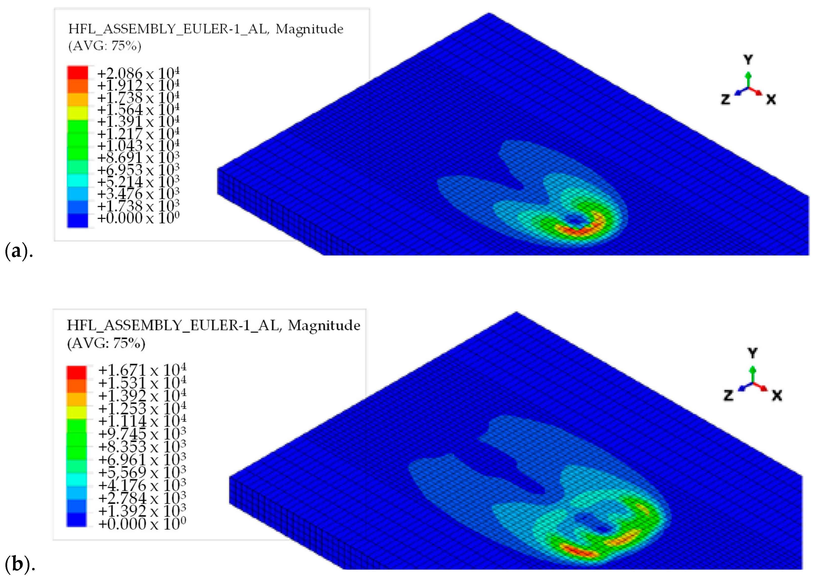
  • Thermal Analysis: by considering factors such as tool rotation, tool traverse speed, and material properties, FEA can simulate the heat generation and distribution predicting the temperature distribution, the thermal cycles, and the heat-affected zone evolution during the welding process. This information is significant for understanding the thermal history and potential defects in the weld.
  • Mechanical Analysis: by considering the interaction between the tool and workpiece, FEA can evaluate the mechanical aspects of FSW, including stress and deformation distribution predicting the material flow, the plastic deformation, and the residual stresses in the weld. This analysis helps to optimize tool geometry and process parameters to minimize residual stresses and distortion in the final weld [227].
  • Process Optimization: FEA allows for parametric studies where different welding parameters and tool designs can be simulated to assess their impact on the welding process. By analyzing the temperature, stress, and deformation fields, FEA can help identify optimal process parameters that lead to improved weld quality, reduced defects, and enhanced mechanical properties.
  • Defect Prediction: FEA can aid in identifying potential defects in the FSW process. For example, by analyzing the temperature field, FEA can predict the likelihood of defects like lack of fusion, voids, or excessive material flow. This information can guide process improvements and minimize the occurrence of defects.
  • Tool Design and Optimization: by simulating the contact and frictional behavior between the tool and the workpiece, FEA can assess tool wear, heat generation, and stress distribution on the tool. This enables the development of tool designs that enhance performance, durability, and efficiency.
The method used in finite element analysis can be divided into implicit, explicit and CFD—that is analysed in the next section—analysis. The implicit analysis method is well suited for static equilibrium cases as it relies on force and momentum equilibrium methods. It provides automated and direct user control of the time step derivative, making it applicable to both linear and non-linear models with significant steps. However, due to the time-consuming nature in fast dynamic processes, these models are more suitable for scenarios where precise results are needed rather than quick calculations. The explicit analysis method is founded on energy equilibrium, enabling it to efficiently tackle dynamic equilibrium problems. It is the preferred choice for scenarios where simulation time is of the utmost importance while maintaining accurate results [228].
The choice of formulations or modelling scales establishes the framework that connects the components or equations of the simulation [228]. Das et al. [229] develop a finite element model using the coupled Eulerian–Lagrangian (CEL) approach for interpreting the tool–material interaction and predicting both the volumetric defect and the surface texture with optimum condition of mass scaling. Several solid mechanics approaches, such as the Eulerian or Lagrangian approach, smoother particle hydrodynamics (SPH), coupled Eulerian and Lagrangian (CEL), and arbitrary Lagrangian and Eulerian (ALE) [230] techniques, can be employed to model the thermo-mechanical behavior of the friction stir welding (FSW) process [231,232,233]. The CEL approach is suitable for the modelling of the dissimilar FSW process [234]. In particular, the analysis of the thermo-mechanical behavior of the FSW process using the coupled Eulerian-Lagrangian method is highly influenced by the mass scaling factor. Customizing this factor to create a computationally efficient model holds great potential in accurately predicting defects in the FSW process. Mass scaling is a key aspect of explicit time integration schemes used in quasi-static simulations of the process, which involves highly nonlinear contact conditions between the FSW tool and the workpiece. Mass scaling enables the discretization of the solution domain into multiple small elements [235]. However, applying mass scaling automatically may not always be feasible, leading researchers to explore a manual approach of multiplying the density with a mass scaling factor, as discussed in the literature [236].
The main software commonly used for modelling the FSW process include ABAQUS, ANSYS [228,237], and DEFORM [238,239]. A wide array of literature exists, but it is focused mainly on similar aluminium alloys due to the fact that the joining of the dissimilar materials is usually more difficult in comparison with the joining of a similar material or those materials that have minor differences [231].
Zahari et al. [240] use the equivalence technique to develop a model of FSW weld and then validate it using experimental modal analysis (EMA) for the prediction of dynamic behaviour in AA6061 and AA7075 joints by varying rotational speed (i.e., 900, 1000 and 1100 rpm), welding speed (i.e., 30, 40 and 50 mm/min) and tilt angle (i.e., 0, 1 and 2 degrees).
Sivasankara Raju et al. [241] investigate dissimilar aluminium alloy sheets AA6061 and AA5052 using Deform 3D to examine the effect of heat generation on the welding process at various tool speeds (i.e., 1000, 1200, 1400 rpm) and feed rates (i.e., 20, 40 and 60 mm/min). The authors evaluate distribution and values of temperature in weld-zones by observing that (i) aluminium alloy sheets have a temperature gradient that increases as they advance and decreases as they retreat; (ii) nugget zone hardness levels are lower than those of the base alloy; (iii) for AA6061, the temperature rises with increasing tool speed and falls with increasing feed rate; (iv) at a constant welding speed, the quantity of heat in the weld zones rises with increasing tool rotational speed; the temperature first increases quickly and then fluctuates before progressively dropping. The model is validated using the thermocouples in suited experimental tests.
Salloomi and Al-Sumaidae [242] investigate the effect of rotational (i.e., 550, 950 rpm) and traverse speeds (i.e., 60, 60 mm/min) on thermal (see Figure 11) and residual stress environments generated in FSW of AA2024-T3 to AA6061-T6 effectively using the CEL finite element algorithm.
Al-Badour et al. [243] develop a thermo-mechanical finite element model based on the CEL method to simulate the friction stir welding of dissimilar Al6061-T6 and Al5083-O aluminium alloys using different tool pin profiles and changing the sheet position at a rotational speed of 900 rpm, a welding speed of 150 mm/min and a tilt angle of 2 degrees. The results from the finite element analysis indicate that the maximum temperatures at the weld joint remained below the melting point of the materials. Positioning the harder alloy (Al6061-T6) on the advancing side causes the maximum process temperature and strain rate to become reduced, although the tool reaction loads increase. Furthermore, employing a specialized tool pin improves the material mixing, resulting in improved joint quality and reduced volumetric defects.
AA2024 is placed on the advancing side while AA6061 is placed on the retreating side. The H13 steel tool is characterised by a 20 mm diameter concave shoulder with a 4 mm diameter tapered threaded pin and a height of 4.7 mm. The authors find that (i) the increase in the tool rotational speed leads to a relative increase in the temperature field, while the increase in the welding traverse speed causes a relatively slight decrease in the temperature field; (ii) the longitudinal residual stress component is higher on the AA6061 side than that on the AA2024 side. This decreases with the increase in the rotational speed while it increases with the increase in the traverse speed; (iii) the plastic strain on the AA6061 side is higher than that of AA2024, contributing highly to the temperature and residual stress fields. These results confirm that the tool rotational speed is more influential than the tool traverse speed.
Karash et al. [244] employ the ANSYS program to predict surface temperatures on three-dimensional models. This research focuses on two aluminium alloys, AA7075-T6 in the retreating side and AA2024-O in the advancing side. The authors first examine temperature variations from the welding centre to the model edges. They then investigate temperature distributions throughout the welding process, from start to finish, and develop equations to predict temperature distributions based on welding time and distance from the welding centre. The study considers various welding speeds (20, 40, 60, and 100 mm/min) and different speeds of the welding tool (900, 1050, and 1200 rpm). The findings reveal that increasing the rotational speed leads to higher temperatures, while increasing the welding speed results in lower temperatures. Additionally, the temperature distribution is observed to be asymmetric, indicating a lack of symmetry in the welding process.

Computational Fluid Dynamics

CFD provides insights into the fluid flow and heat transfer phenomena that occur during welding [245,246,247]. The primary concept behind this form of analysis involves replacing a continuous problem domain with a discrete domain. This is achieved by applying a grid to the area of interest and subsequently making approximations of the governing equations [228].
CFD allows to simulate and analyze the complex fluid flow patterns, temperature distributions, and material deformation that take place during FSW. It helps in understanding the fundamental physics of the process, optimizing process parameters, and predicting the resulting weld quality.
In particular, CFD allows to study the following aspects:
  • Fluid flow analysis: it helps in understanding the velocity profiles, the flow patterns, and the material displacement within the workpiece. By analyzing the fluid flow, it is possible to study the mixing and stirring of materials and identify regions of potential defects or inhomogeneity.
  • Temperature distribution: by accounting for factors like heat generation, heat transfer, and cooling mechanisms, CFD simulations provide valuable insights into the temperature profiles and the gradients that influence the weld quality. This information helps in optimizing the welding parameters to control the heat input and avoid defects like overheating or insufficient heating.
  • Residual stress and distortion analysis: the thermal and mechanical interactions between the tool, workpiece, and surrounding environment can be analyzed to predict the residual stresses and distortions that arise after welding. Understanding these effects aids in optimizing process parameters, tool design, and subsequent post-welding operations.
  • Process optimization: CFD simulations allow for virtual experimentation, enabling the exploration of different process variables without the need for physical prototypes. It is possible to analyze the effects of tool geometry, rotational speed, traverse speed, and other parameters on the fluid flow, temperature distribution, and resulting weld quality [248].
Tang and Shen [249] develop a new CFD based model which is more suitable to simulate the heat transfer in dissimilar AA2024-AA7075 joints. The tool made of a tungsten alloy consists of a cylindrical shoulder of 25 mm in diameter and a conical pin of 8 mm and 6 mm in the upper and lower diameter, respectively, and 5 mm in length. It rotates at 1000 rpm and moves with a feed rate of 72 mm/min. The results clearly demonstrate a noticeable asymmetric temperature distribution between the advancing side and the retreating side. Additionally, the temperature profile exhibits discontinuity due to variations in material properties such as heat capacity, viscosity, and thermal conductivity. The mutual interaction between temperature and material properties further amplifies the disparities in the workpiece’s temperature distribution. Furthermore, welding time plays a crucial role in determining the welding temperature. The temperature curves reveal a rapid increase followed by a slower decrease in temperature.
Padmanaban et al. [250] investigate the joining of dissimilar alloys AA2024 and AA7075 developing a numerical model based on CFD. The authors perform the process with a HSS taper threaded tool displaying a shoulder diameter of 17.5 mm, a pin diameter of 5 mm and a pin height of 4.65 mm by changing the rotational speed from 900 rpm to 1200 rpm and altering the welding speed from 20 mm/min to 60 mm/min. In particular, they model the process using a viscoelastic stream beyond a rotating cylindrical tool. The result shows that the peak temperature increases with tool rotation speed and shoulder diameter but decreases with welding speed (see Figure 12 and Figure 13).
In Table 7, the main outcomes of the examined design tools are summarized.

4. Conclusions

This review is characterized by two goals, i.e., highlighting the main process parameters in a friction stir welding process between two dissimilar aluminum alloys and showing the main tools to design and predict the mechanical behavior of dissimilar aluminum joints.
Although this joining technology is relatively new, a wide array of literature exists on the optimization of the process for both similar and dissimilar materials and also for both similar and dissimilar aluminum alloys. However, the thermal, mechanical, and metallurgical aspects during the process are so complex that significant experimental testing is required with an uncertain result about the more relevant parameters influencing strength, microhardness, or other mechanical properties. This is just more complicated if the materials to be joined are different. In this context, the literature on this topic is always in continuous evolution.
As for the tool shoulder and pin geometry, it is possible summarize the following: considering the significant effect of tool geometry on metal flow, heat generation, stirring effect, recrystallization, fundamental correlation between material flow and resultant microstructure of welds varies with each tool. From the literature, the results are not always concordant; in general, to join two different aluminum alloys in the range of 3–8 mm, a square pin produces good metal flow and, consequently, a good stirring with respect to triangular or stepped ones; on the contrary, it can be affected by adhesion with the stirred material and can lead to several defects. Moreover, it cannot be used at higher speeds; then, cylindrical or conical pins are preferred. In the field of cylindrical pins, the ones with more complex surfaces like cylindrical threaded pins with three flat faces tool pins and cylindrical grooved tool pins—at intermediate tool rotation and feed rate—have to be preferred because they lead to good tensile and flexural strength; the presence of grooves or scrolls in the shoulder favors the material flow from the edge of the shoulder to the pin, thus eliminating to tilt the tool to void or tunnel defects. These considerations, however, must take into account the strong correlation with other parameters, mainly tool rotational and welding (or traverse) speeds and the tilt angle. Consequently, a critical need is to develop systematic frameworks for tool design that can focus on the different operative conditions (kind of alloy thickness of the sheets, tool material).
  • As for the tool tilt angle, angles between 1° and 3° favor the material flow allowing the increase in speeds and avoiding defects in the joint, the presence of groves or scrolls on the shoulder thus eliminated to tilt the tool.
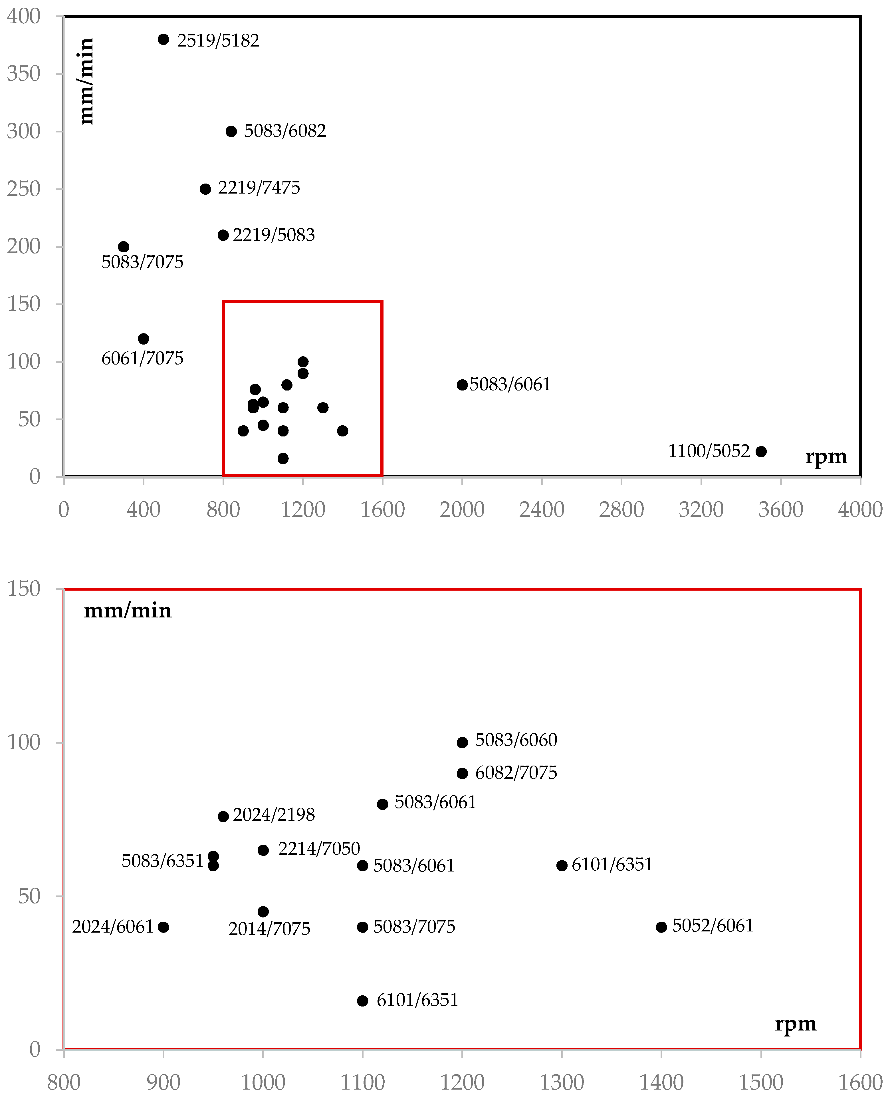
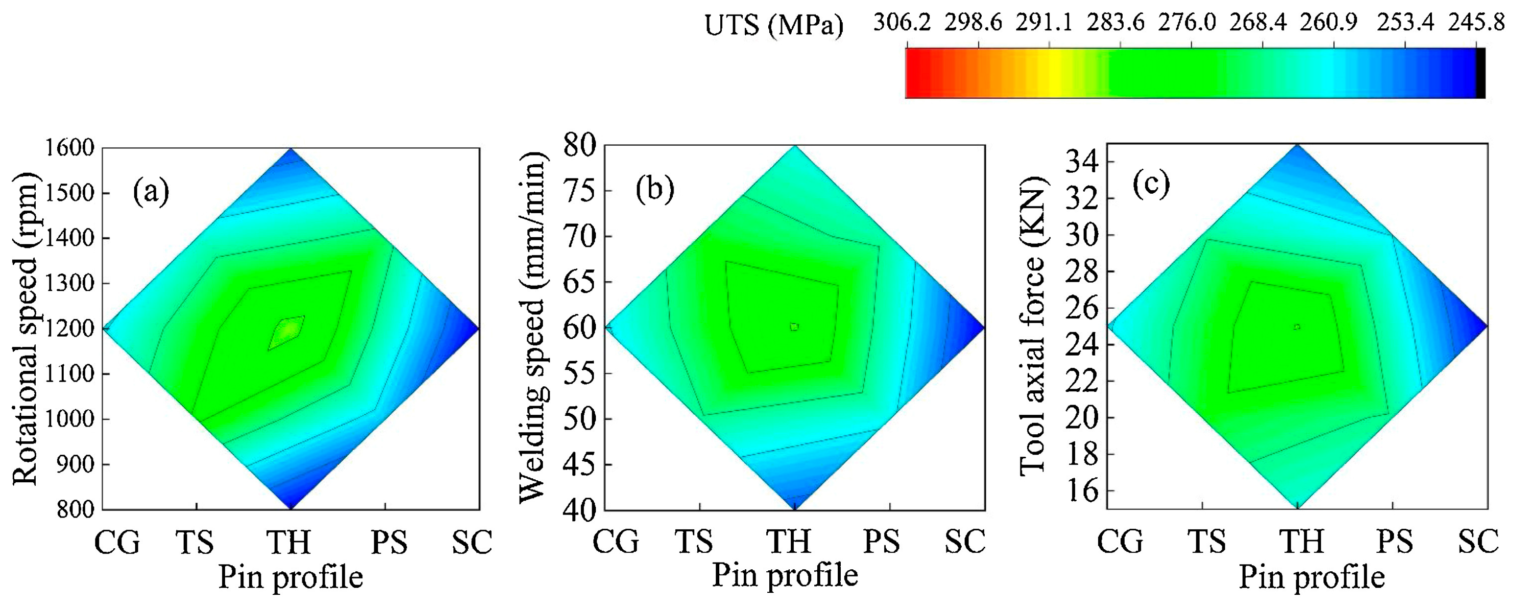
  • As for rotational and traverse speeds, these two parameters have a strong interaction and an inverse correlation. Higher tool rotation speeds and lower tool traverse speeds promote intimate mixing between dissimilar alloys. As rotational speed increases (from 1000 to 1200 rpm) and traverse speed decreases (from 120 to 90 mm/min), both factors contribute to increased heat generation, higher peak temperatures, and reduced maximum tensile residual stress.
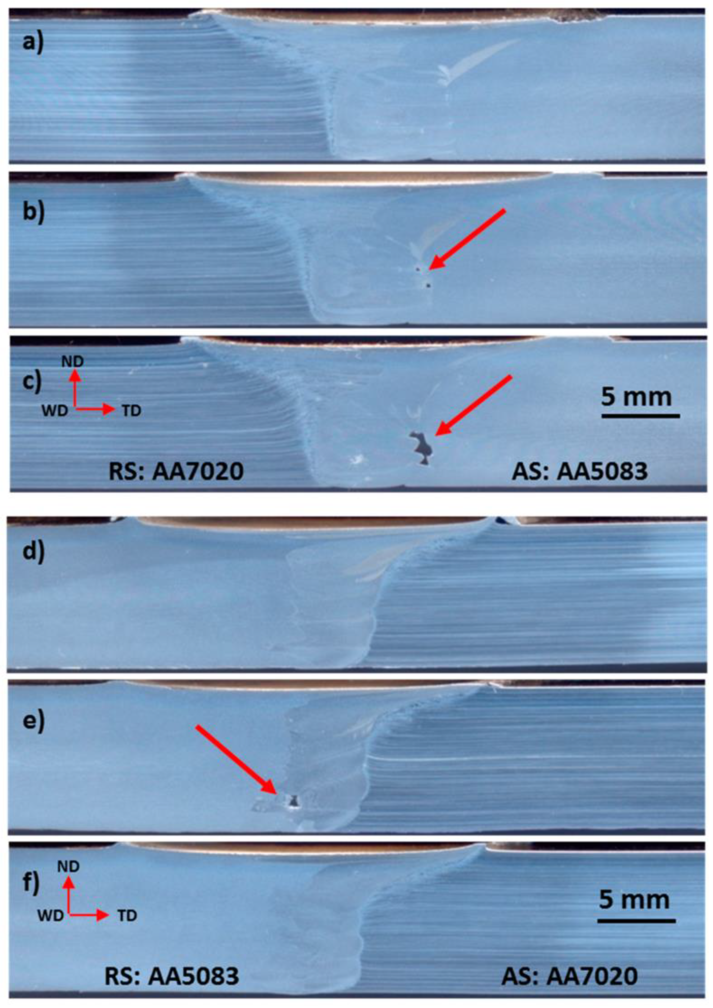
  • As for the position of the sheets (AS/RS), there is not always a complete agreement among the experimental results that are performed with different tool shapes, tilt angle and tool speeds. Most of them, however, agree on the fact that the higher mechanical properties of the weld zone were acquired when a relatively harder material was fixed at the retreating side.
  • Finally, the axial force should be adjusted within the optimal range to achieve a balance between material deformation and process stability.
Moreover, to offer an added value to the review, the main design tools are presented:
  • The statistical approach inside a proper design of sxperiment is one of the most robust tools that researchers can use. Statistical analysis can be employed to investigate the relationship between process parameters, microstructure evolution, and resulting mechanical properties. This understanding helps researchers optimize the welding process for specific applications and predict material behavior under different loading conditions. Statistical approaches can also aid in assessing the reliability and fatigue life of FSW joints. By applying probabilistic models and using techniques like the Weibull analysis, researchers can estimate the probability of failure or predict the fatigue life of welds under different loading conditions. This information is vital for ensuring the long-term performance and durability of FSW structures. The previously cited goals can be obtained expanding the information using heuristic techniques (like neural networks and genetic algorithms), thus reducing the need for experiments. In addition, the latter tools can be successfully used for real-time monitoring and controlling of the welding process.
  • On the contrary, numerical modelling like finite element analysis and Computational Fluid Dynamics are very powerful tools for researchers to study/analyze/predict the characteristics of the joint at all the varying parameters cited above. The extremely complex thermal/mechanical and metallurgical phenomena involved in the FSW process cannot be described by mathematical models; thus, the latter two approaches are the only valid support to design tools and/or optimize the process.

Author Contributions

Conceptualization, C.B. and G.D.B.; methodology, C.B. and G.D.B.; data curation, C.B., G.D.B. and F.F.; writing—original draft preparation, G.D.B. and F.F.; writing—review and editing, C.B., G.D.B. and F.F.; supervision, C.B. All authors have read and agreed to the published version of the manuscript.

Funding

This research received no external funding.

Data Availability Statement

This research shared no data.

Conflicts of Interest

The authors declare no conflict of interest.

References

  1. Torzewski, J.; Łazińska, M.; Grzelak, K.; Szachogłuchowicz, I.; Mierzyński, J. Microstructure and Mechanical Properties of Dissimilar Friction Stir Welded Joint AA7020/AA5083 with Different Joining Parameters. Materials 2022, 15, 1910. [Google Scholar] [CrossRef]
  2. Kaushal, A.; Shankar, S.; Chattopadhyaya, S. Joining of Dissimilar Aluminum Alloys AA2024 and AA7075 by Friction Stir Welding: A Review. In Recent Advances in Manufacturing, Automation, Design and Energy Technologies; Springer: Singapore, 2022; pp. 95–103. [Google Scholar]
  3. Sivaraman, P.; Nithyanandhan, T.; Karthick, M.; Kirivasan, S.M.; Rajarajan, S.; Sundar, M.S. Analysis of Tensile Strength of AA 2014 and AA 7075 Dissimilar Metals Using Friction Stir Welding. Mater. Today Proc. 2021, 37, 187–192. [Google Scholar] [CrossRef]
  4. Maddox, S. Review of Fatigue Assessment Procedures for Welded Aluminium Structures. Int. J. Fatigue 2003, 25, 1359–1378. [Google Scholar] [CrossRef]
  5. Boopathi, S.; Moorthi, K. Review on Effect of Process Parameters-Friction Stir Welding Process. Int. Res. J. Eng. Technol. 2017, 4, 272–278. [Google Scholar]
  6. Ahmed, M.M.Z.; El-Sayed Seleman, M.M.; Fydrych, D.; Çam, G. Friction Stir Welding of Aluminum in the Aerospace Industry: The Current Progress and State-of-the-Art Review. Materials 2023, 16, 2971. [Google Scholar] [CrossRef]
  7. Ahmed, S.; ur Rahman, R.A.; Awan, A.; Ahmad, S.; Akram, W.; Amjad, M.; Yahya, M.Y.; Rahimian Koloor, S.S. Optimization of Process Parameters in Friction Stir Welding of Aluminum 5451 in Marine Applications. J. Mar. Sci. Eng. 2022, 10, 1539. [Google Scholar] [CrossRef]
  8. Napolitano, F.; El Hassanin, A.; Scherillo, F.; Squillace, A. FSW of Extruded and Additively Manufactured Parts for Automotive Components. Mater. Manuf. Process. 2023, 38, 1445–1454. [Google Scholar] [CrossRef]
  9. Prakash, P.; Anand, R.S.; Jha, S.K. Experimental Analysis of Tensile Strength of Different Thicknesses and Dissimilar Aluminum Alloys in Friction Stir Welding. J. Mater. Eng. Perform. 2022, in press. [Google Scholar] [CrossRef]
  10. Christy, J.V.; Mourad, A.-H.I.; Sherif, M.M.; Shivamurthy, B. Review of Recent Trends in Friction Stir Welding Process of Aluminum Alloys and Aluminum Metal Matrix Composites. Trans. Nonferrous Met. Soc. China 2021, 31, 3281–3309. [Google Scholar] [CrossRef]
  11. Verma, R.P.; Pandey, K.N.; András, K.; Khargotra, R.; Singh, T. Difficulties and Redressal in Joining of Aluminium Alloys by GMA and GTA Welding: A Review. J. Mater. Res. Technol. 2023, 23, 2576–2586. [Google Scholar] [CrossRef]
  12. Di Bella, G.; Borsellino, C.; Khaskhoussi, A.; Proverbio, E. Effect of Tool Rotation Direction on Mechanical Strength of Single Lap Friction Stir Welded Joints between AA5083 Aluminum Alloy and S355J0 Steel for Maritime Applications. Metals 2023, 13, 411. [Google Scholar] [CrossRef]
  13. Cabibbo, M.; Forcellese, A.; Santecchia, E.; Paoletti, C.; Spigarelli, S.; Simoncini, M. New Approaches to Friction Stir Welding of Aluminum Light-Alloys. Metals 2020, 10, 233. [Google Scholar] [CrossRef] [Green Version]
  14. Gullino, A.; Matteis, P.; D’Aiuto, F. Review of Aluminum-To-Steel Welding Technologies for Car-Body Applications. Metals 2019, 9, 315. [Google Scholar] [CrossRef] [Green Version]
  15. Khaskhoussi, A.; Di Bella, G.; Borsellino, C.; Calabrese, L.; Proverbio, E. Microstructural and Electrochemical Characterization of Dissimilar Joints of Aluminum Alloy AW5083 and Carbon Steel S355 Obtained by Friction Welding. Metall. Ital. 2022, 9, 15–21. [Google Scholar]
  16. Meschut, G.; Merklein, M.; Brosius, A.; Drummer, D.; Fratini, L.; Füssel, U.; Gude, M.; Homberg, W.; Martins, P.A.F.; Bobbert, M.; et al. Review on Mechanical Joining by Plastic Deformation. J. Adv. Join. Process. 2022, 5, 100113. [Google Scholar] [CrossRef]
  17. Prabhakar, D.A.P.; Shettigar, A.K.; Herbert, M.A.; Patel, G.C.M.; Pimenov, D.Y.; Giasin, K.; Prakash, C. A Comprehensive Review of Friction Stir Techniques in Structural Materials and Alloys: Challenges and Trends. J. Mater. Res. Technol. 2022, 20, 3025–3060. [Google Scholar] [CrossRef]
  18. Nguyen, T.-T.; Nguyen, C.-T.; Van, A.-L. Sustainability-Based Optimization of Dissimilar Friction Stir Welding Parameters in Terms of Energy Saving, Product Quality, and Cost-Effectiveness. Neural Comput. Appl. 2023, 35, 5221–5249. [Google Scholar] [CrossRef]
  19. Kaygusuz, E.; Karaomerloglu, F.; Akinci, S. A Review of Friction Stir Welding Parameters, Process and Application Fields. Turk. J. Eng. 2023, 7, 286–295. [Google Scholar] [CrossRef]
  20. Ravi Kumar, B.V.R.; Upender, K.; Venkata Ramana, M.; Sreenivasarao, M.S. Visual Inspection on Friction Stir Welded Dissimilar Aluminum Alloy AA6082-AA5083 Using Conventional and Hybrid Tool Pin Profiles. Mater. Today Proc. 2023, in press. [Google Scholar] [CrossRef]
  21. Rabiezadeh, A.; Salafzon, A.; Mostafavi, N. Dissimilar Welding of AA5083/AA7039 by Self-Reacting Friction Stir Welding. J. Adhes. Sci. Technol. 2023, 1–22. [Google Scholar] [CrossRef]
  22. Hou, W.; Ding, Y.; Huang, G.; Huda, N.; Shah, L.H.A.; Piao, Z.; Shen, Y.; Shen, Z.; Gerlich, A. The Role of Pin Eccentricity in Friction Stir Welding of Al-Mg-Si Alloy Sheets: Microstructural Evolution and Mechanical Properties. Int. J. Adv. Manuf. Technol. 2022, 121, 7661–7675. [Google Scholar] [CrossRef]
  23. Ahmad Shah, L.H.; Midawi, A.R.H.; Walbridge, S.; Gerlich, A. Influence of Tool Eccentricity on the Material Flow and Microstructural Properties of AA6061 Aluminum Alloy Friction Stir Welds. J. Alloys Compd. 2020, 826, 154219. [Google Scholar] [CrossRef]
  24. Shah, L.H.; Huda, N.; Esmaeili, S.; Walbridge, S.; Gerlich, A.P. Structural Morphology of Al-Mg-Si Alloy Friction Stir Welds through Tool Eccentricity. Mater. Lett. 2020, 275, 128098. [Google Scholar] [CrossRef]
  25. Pookamnerd, Y.; Thosa, P.; Charonerat, S.; Prasomthong, S. Development of Mechanical Property Prediction Model and Optimization for Dissimilar Aluminum Alloy Joints with the Friction Stir Welding (FSW) Process. EUREKA Phys. Eng. 2023, 3, 112–128. [Google Scholar] [CrossRef]
  26. Cao, F.; Sun, T.; Hu, J.; Hou, W.; Huang, G.; Shen, Y.; Ma, N.; Geng, P.; Hu, W.; Qu, X. Enhanced Mechanical and Anticorrosion Properties in Cryogenic Friction Stir Processed Duplex Stainless Steel. Mater. Des. 2023, 225, 111492. [Google Scholar] [CrossRef]
  27. Sun, S.J.; Tian, Y.Z.; An, X.H.; Lin, H.R.; Wang, J.W.; Zhang, Z.F. Ultrahigh Cryogenic Strength and Exceptional Ductility in Ultrafine-Grained CoCrFeMnNi High-Entropy Alloy with Fully Recrystallized Structure. Mater. Today Nano 2018, 4, 46–53. [Google Scholar] [CrossRef]
  28. Patel, M.; Murugesan, J. Effect of the Tool Pin Eccentricity and Cooling Rate on Microstructure, Mechanical Properties, Fretting Wear, and Corrosion Behavior of Friction Stir Processed AA6063 Alloy. J. Mater. Eng. Perform. 2022, 31, 8554–8566. [Google Scholar] [CrossRef]
  29. Sabry, N.; Stroh, J.; Sediako, D. Characterization of Microstructure and Residual Stress Following the Friction Stir Welding of Dissimilar Aluminum Alloys. CIRP J. Manuf. Sci. Technol. 2023, 41, 365–379. [Google Scholar] [CrossRef]
  30. Mertinger, V.; Varbai, B.; Adonyi, Y.; DeBacker, J.; Nagy, E.; Leskó, M.; Kárpáti, V. Microstructure Evaluation of Dissimilar AA2024 and AA7050 Aluminum Joints Made by Corner Stationary-Shoulder Friction Stir Welding. Weld. World 2022, 66, 1623–1635. [Google Scholar] [CrossRef]
  31. Patel, V.; Li, W.; Wang, G.; Wang, F.; Vairis, A.; Niu, P. Friction Stir Welding of Dissimilar Aluminum Alloy Combinations: State-of-the-Art. Metals 2019, 9, 270. [Google Scholar] [CrossRef] [Green Version]
  32. Khalafe, W.H.; Sheng, E.L.; Bin Isa, M.R.; Omran, A.B.; Shamsudin, S. Bin The Effect of Friction Stir Welding Parameters on the Weldability of Aluminum Alloys with Similar and Dissimilar Metals: Review. Metals 2022, 12, 2099. [Google Scholar] [CrossRef]
  33. Prabhu, S.; Sri, M.N.S.; Anusha, P.; Saravanan, G.; Kannan, K.; Manickam, S. Improvement of Mechanical Behavior of FSW Dissimilar Aluminum Alloys by Postweld Heat Treatments. Adv. Mater. Sci. Eng. 2022, 2022, 3608984. [Google Scholar] [CrossRef]
  34. Cavaliere, P.; Nobile, R.; Panella, F.W.; Squillace, A. Mechanical and Microstructural Behaviour of 2024–7075 Aluminium Alloy Sheets Joined by Friction Stir Welding. Int. J. Mach. Tools Manuf. 2006, 46, 588–594. [Google Scholar] [CrossRef]
  35. Tucci, F.; Carlone, P.; Silvestri, A.T.; Parmar, H.; Astarita, A. Dissimilar Friction Stir Lap Welding of AA2198-AA6082: Process Analysis and Joint Characterization. CIRP J. Manuf. Sci. Technol. 2021, 35, 753–764. [Google Scholar] [CrossRef]
  36. Battina, N.M.; Vanthala, V.S.P.; Ch, H.K. Effect of Friction Stir Welding Process Parameters on Mechanical and Metallurgical Behavior of AA6061-T6 and AA2017-T6 Tailored Blanks. Eng. Res. Express 2021, 3, 025043. [Google Scholar] [CrossRef]
  37. Abnar, B.; Gashtiazar, S.; Javidani, M. Friction Stir Welding of Non-Heat Treatable Al Alloys: Challenges and Improvements Opportunities. Crystals 2023, 13, 576. [Google Scholar] [CrossRef]
  38. de Viveiros, B.V.G.; da Silva, R.M.P.; Donatus, U.; Costa, I. Welding and Galvanic Coupling Effects on the Electrochemical Activity of Dissimilar AA2050 and AA7050 Aluminum Alloys Welded by Friction Stir Welding (FSW). Electrochim. Acta 2023, 449, 142196. [Google Scholar] [CrossRef]
  39. Essa, A.; Ahmed, M.; Mohamed, A. Weld Pitch Effects on Friction Stir Welding of Aluminum Alloys. J. Pet. Min. Eng. 2021, 23, 102–106. [Google Scholar] [CrossRef]
  40. Tiwari, S.; Shukla, D.K.; Chandra, R. Friction Stir Welding of Aluminum Alloys: A Review. Int. J. Mech. Aerosp. Ind. Mechatron. Eng. 2013, 7, 1315–1320. [Google Scholar]
  41. Shyamlal, C.; Rajesh, S.; Suresh Kumar, S. A Comprehensive Review on the Effect of Precipitation on Mechanical Properties of Friction Stir Welded Aluminium Alloys. Proc. Inst. Mech. Eng. C J. Mech. Eng. Sci. 2021, 235, 6345–6356. [Google Scholar] [CrossRef]
  42. Beygi, R.; Talkhabi, A.A.; Mehrizi, M.Z.; Marques, E.A.S.; Carbas, R.J.C.; da Silva, L.F.M. A Novel Lap-Butt Joint Design for FSW of Aluminum to Steel in Tee-Configuration: Joining Mechanism, Intermetallic Formation, and Fracture Behavior. Metals 2023, 13, 1027. [Google Scholar] [CrossRef]
  43. Beygi, R.; Galvão, I.; Akhavan-Safar, A.; Pouraliakbar, H.; Fallah, V.; da Silva, L.F.M. Effect of Alloying Elements on Intermetallic Formation during Friction Stir Welding of Dissimilar Metals: A Critical Review on Aluminum/Steel. Metals 2023, 13, 768. [Google Scholar] [CrossRef]
  44. Beygi, R.; Carbas, R.J.C.; Barbosa, A.Q.; Marques, E.A.S.; da Silva, L.F.M. Buttering for FSW: Enhancing the Fracture Toughness of Al-Fe Intermetallics through Nanocrystallinity and Suppressing Their Growth. J. Manuf. Process. 2023, 90, 233–241. [Google Scholar] [CrossRef]
  45. Buffa, G.; Baffari, D.; Di Caro, A.; Fratini, L. Friction Stir Welding of Dissimilar Aluminium–Magnesium Joints: Sheet Mutual Position Effects. Sci. Technol. Weld. Join. 2015, 20, 271–279. [Google Scholar] [CrossRef]
  46. Ambrosio, D.; Wagner, V.; Dessein, G.; Paris, J.-Y.; Jlaiel, K.; Cahuc, O. Plastic Behavior-Dependent Weldability of Heat-Treatable Aluminum Alloys in Friction Stir Welding. Int. J. Adv. Manuf. Technol. 2021, 117, 635–652. [Google Scholar] [CrossRef]
  47. Lu, H.; Xu, W.; Wang, H.; Wang, X.-Z. Microstructure Evolution and Its Effect on the Corrosion of Dissimilar Aluminum Alloys Friction Stir Welding Joint. Corros. Sci. 2023, 220, 111249. [Google Scholar] [CrossRef]
  48. Meng, X.; Huang, Y.; Cao, J.; Shen, J.; dos Santos, J.F. Recent Progress on Control Strategies for Inherent Issues in Friction Stir Welding. Prog. Mater. Sci. 2021, 115, 100706. [Google Scholar] [CrossRef]
  49. Leng, L.; Zhang, Z.J.; Duan, Q.Q.; Zhang, P.; Zhang, Z.F. Improving the Fatigue Strength of 7075 Alloy through Aging. Mater. Sci. Eng. A 2018, 738, 24–30. [Google Scholar] [CrossRef]
  50. Liu, H.J.; Chen, Y.C.; Feng, J.C. Effect of heat treatment on tensile properties of friction stir welded joints of 2219-T6 aluminium alloy. Mat. Sci. Technol. 2006, 22, 237–241. [Google Scholar] [CrossRef]
  51. Karlsen, M.; Frigaard, Ø.; Hjelen, J.; Grong, Ø.; Norum, H. SEM-EBSD Characterisation of the Deformation Microstructure in Friction Stir Welded 2024 T351 Aluminium Alloy. In Materials Science Forum; Trans Tech Publications: Bäch, Switzerland, 2003; pp. 2861–2866. [Google Scholar] [CrossRef]
  52. Linton, V.M.; Ripley, M.I. Influence of Time on Residual Stresses in Friction Stir Welds in Agehardenable 7xxx Aluminium Alloys. Acta Mater. 2008, 56, 4319–4327. [Google Scholar] [CrossRef]
  53. Sato, Y.S.; Kokawa, H.; Enomoto, M.; Jogan, S.; Hashimoto, T. Precipitation Sequence in Friction Stir Weld of 6063 Aluminum during Aging. Metall. Mater. Trans. A 1999, 30, 3125–3130. [Google Scholar] [CrossRef]
  54. Sato, Y.S.; Kokawa, H. Distribution of Tensile Property and Microstructure in Friction Stir Weld of 6063 Aluminum. Metall. Mater. Trans. A 2001, 32, 3023–3031. [Google Scholar] [CrossRef]
  55. Kalemba, I.; Hamilton, C.; Dymek, S. Natural Aging in Friction Stir Welded 7136-T76 Aluminum Alloy. In Friction Stir Welding and Processing VIII; Springer International Publishing: Cham, Switzerland, 2015; pp. 107–114. [Google Scholar]
  56. Liu, H.J.; Fujii, H.; Maeda, M.; Nogi, K. Mechanical Properties of Friction Stir Welded Joints of 1050—H24 Aluminium Alloy. Sci. Technol. Weld. Join. 2003, 8, 450–454. [Google Scholar] [CrossRef]
  57. Threadgill, P.L. Terminology in Friction Stir Welding. Sci. Technol. Weld. Join. 2007, 12, 357–360. [Google Scholar] [CrossRef]
  58. Abnar, B.; Kazeminezhad, M.; Kokabi, A.H. Effects of Heat Input in Friction Stir Welding on Microstructure and Mechanical Properties of AA3003-H18 Plates. Trans. Nonferrous Met. Soc. China 2015, 25, 2147–2155. [Google Scholar] [CrossRef]
  59. Beygi, R.; Zarezadeh Mehrizi, M.; Akhavan-Safar, A.; Mohammadi, S.; da Silva, L.F.M. A Parametric Study on the Effect of FSW Parameters and the Tool Geometry on the Tensile Strength of AA2024–AA7075 Joints: Microstructure and Fracture. Lubricants 2023, 11, 59. [Google Scholar] [CrossRef]
  60. Bussu, G.; Irving, P. The Role of Residual Stress and Heat Affected Zone Properties on Fatigue Crack Propagation in Friction Stir Welded 2024-T351 Aluminium Joints. Int. J. Fatigue 2003, 25, 77–88. [Google Scholar] [CrossRef]
  61. James, M.N.; Bradley, G.R.; Lombard, H.; Hattingh, D.G. The Relationship between Process Mechanisms and Crack Paths in Friction Stir Welded 5083-H321 and 5383-H321 Aluminium Alloys. Fatigue Fract. Eng. Mater. Struct. 2005, 28, 245–256. [Google Scholar] [CrossRef]
  62. Frigaard, Ø.; Grong, Ø.; Midling, O.T. A Process Model for Friction Stir Welding of Age Hardening Aluminum Alloys. Metall. Mater. Trans. A 2001, 32, 1189–1200. [Google Scholar] [CrossRef]
  63. Dimopoulos, A.; Vairis, A.; Vidakis, N.; Petousis, M. On the Friction Stir Welding of Al 7075 Thin Sheets. Metals 2020, 11, 57. [Google Scholar] [CrossRef]
  64. Lertora, E.; Campanella, D.; Pizzorni, M.; Mandolfino, C.; Buffa, G.; Fratini, L. Comparative Evaluation of the Effect of the Substrate Thickness and Inherent Process Defects on the Static and Fatigue Performance of FSW and Adhesive-Bonded Overlap-Joints in an AA6016 Alloy. J. Manuf. Process. 2021, 64, 785–792. [Google Scholar] [CrossRef]
  65. Beygi, R.; Marques, E.; da Silva, L.F.M. Computational Concepts in Simulation of Welding Processes; Springer: Cham, Switzerland, 2022. [Google Scholar]
  66. Imam, M.; Sun, Y.; Fujii, H.; Aoki, Y.; MA, N.; Tsutsumi, S.; Murakawa, H. Friction Stir Welding of Thick Aluminium Welds—Challenges and Perspectives. In Friction Stir Welding and Processing IX; Springer: Cham, Switzerland, 2017; pp. 119–124. [Google Scholar]
  67. Perrett, J.G.; Martin, J.; Threadgill, P.L.; Ahmed, M.M.Z. Recent Developments in Friction Stir Welding of Thick Section Aluminium Alloys. In Proceedings of the 6th World Congress, Aluminium Two Thousand, Florence, Italy, 13–17 March 2007. [Google Scholar]
  68. Yuan, K.; Yu, H.; Xu, X.; Zheng, B. Semi-Analytical Model for Material Flow Behavior in Thick Plates via Friction Stir Welding. Int. J. Adv. Manuf. Technol. 2022, 121, 487–501. [Google Scholar] [CrossRef]
  69. Mallieswaran, K.; Padmanabhan, R. Effect of Sheet Thickness on the FSW Parameters for Dissimilar Aluminium Grades Tailor Welded Blanks. Adv. Mater. Process. Technol. 2021, 7, 150–165. [Google Scholar] [CrossRef]
  70. Mamgain, A.; Singh, V.; Pratap Singh, A. Influence of Welding Parameters on Mechanical Property during Friction Stir Welded Joint on Aluminium Alloys: A Review. J. Kejuruter. 2023, 35, 13–28. [Google Scholar] [CrossRef]
  71. Sunnapu, C.; Kolli, M. Tool Shoulder and Pin Geometry’s Effect on Friction Stir Welding: A Study of Literature. Mater. Today Proc. 2021, 39, 1565–1569. [Google Scholar] [CrossRef]
  72. Maji, P.; Karmakar, R.; Kanti Nath, R.; Paul, P. An Overview on Friction Stir Welding/Processing Tools. Mater. Today Proc. 2022, 58, 57–64. [Google Scholar] [CrossRef]
  73. Kalemba-Rec, I.; Kopyściański, M.; Miara, D.; Krasnowski, K. Effect of Process Parameters on Mechanical Properties of Friction Stir Welded Dissimilar 7075-T651 and 5083-H111 Aluminum Alloys. Int. J. Adv. Manuf. Technol. 2018, 97, 2767–2779. [Google Scholar] [CrossRef] [Green Version]
  74. Ghaffarpour, M.; Kazemi, M.; Mohammadi Sefat, M.J.; Aziz, A.; Dehghani, K. Evaluation of Dissimilar Joints Properties of 5083-H12 and 6061-T6 Aluminum Alloys Produced by Tungsten Inert Gas and Friction Stir Welding. Proc. Inst. Mech. Eng. Part L J. Mater. Des. Appl. 2017, 231, 297–308. [Google Scholar] [CrossRef]
  75. Bijanrostami, K.; Barenji, R.V.; Hashemipour, M. Effect of Traverse and Rotational Speeds on the Tensile Behavior of the Underwater Dissimilar Friction Stir Welded Aluminum Alloys. J. Mater. Eng. Perform. 2017, 26, 909–920. [Google Scholar] [CrossRef]
  76. Reza-E-Rabby, M.; Tang, W.; Reynolds, A.P. Effect of Tool Pin Features on Process Response Variables during Friction Stir Welding of Dissimilar Aluminum Alloys. Sci. Technol. Weld. Join. 2015, 20, 425–432. [Google Scholar] [CrossRef]
  77. Muthu Vaidyanathan, R.; Sivaraman, N.; Patel, M.; Woldegioris, M.M.; Atiso, T.A. A Review on the Effects of Shoulder Diameter to Pin Diameter (D/d) Ratio on Friction Stir Welded Aluminium Alloys. Mater. Today Proc. 2021, 45, 4792–4798. [Google Scholar] [CrossRef]
  78. Chandana, R.; Saraswathamma, K. Impact of Tool Pin Profiles in Friction Stir Welding Process—A Review. Mater. Today Proc. 2023, 76, 602–606. [Google Scholar] [CrossRef]
  79. Azmal Hussain, M.; Zaman Khan, N.; Noor Siddiquee, A.; Akhtar Khan, Z. Effect of Different Tool Pin Profiles On The Joint Quality Of Friction Stir Welded AA 6063. Mater. Today Proc 2018, 5, 4175–4182. [Google Scholar] [CrossRef]
  80. Arora, A.; De, A.; DebRoy, T. Toward Optimum Friction Stir Welding Tool Shoulder Diameter. Scr. Mater. 2011, 64, 9–12. [Google Scholar] [CrossRef]
  81. Ramanjaneyulu, K.; Madhusudhan Reddy, G.; Venugopal Rao, A.; Markandeya, R. Structure-Property Correlation of AA2014 Friction Stir Welds: Role of Tool Pin Profile. J. Mater. Eng. Perform. 2013, 22, 2224–2240. [Google Scholar] [CrossRef]
  82. Thomas, W.M.; Johnson, K.I.; Wiesner, C.S. Friction Stir Welding—Recent Developments in Tool and Process Technologies. Adv. Eng. Mater. 2003, 5, 485–490. [Google Scholar] [CrossRef]
  83. Khan, N.Z.; Khan, Z.A.; Siddiquee, A.N. Effect of Shoulder Diameter to Pin Diameter (D/d) Ratio on Tensile Strength of Friction Stir Welded 6063 Aluminium Alloy. Mater. Today Proc. 2015, 2, 1450–1457. [Google Scholar] [CrossRef]
  84. Vijayavel, P.; Balasubramanian, V.; Sundaram, S. Effect of Shoulder Diameter to Pin Diameter (D/d) Ratio on Tensile Strength and Ductility of Friction Stir Processed LM25AA-5% SiCp Metal Matrix Composites. Mater. Des. 2014, 57, 1–9. [Google Scholar] [CrossRef]
  85. Sahlot, P.; Jha, K.; Dey, G.K.; Arora, A. Wear-Induced Changes in FSW Tool Pin Profile: Effect of Process Parameters. Metall. Mater. Trans. A 2018, 49, 2139–2150. [Google Scholar] [CrossRef]
  86. Meilinger, Á.; Török, I. The Importance of Friction Stir Welding Tool. Prod. Process. Syst. 2013, 6, 25–34. [Google Scholar]
  87. Joshi, S.K.; Gandhi, J.D. Influence of Tool Shoulder Geometry on Friction Stir Welding: A Literature Review. In Proceedings of the 2nd International Conference on Multidisciplinary Research & Practice, Gujarat, India, 24 December 2015; pp. 261–264. [Google Scholar]
  88. Verma, S.; Kumar, V. Optimization of Friction Stir Welding Parameters of Dissimilar Aluminium Alloys 6061 and 5083 by Using Response Surface Methodology. Proc. Inst. Mech. Eng. C J. Mech. Eng. Sci. 2021, 235, 7009–7020. [Google Scholar] [CrossRef]
  89. Palanivel, R.; Laubscher, R.; Vigneshwaran, S.; Dinaharan, I. Prediction and Optimization of the Mechanical Properties of Dissimilar Friction Stir Welding of Aluminum Alloys Using Design of Experiments. Proc. Inst. Mech. Eng. B J. Eng. Manuf. 2018, 232, 1384–1394. [Google Scholar] [CrossRef]
  90. Azmi, M.H.; Hasnol, M.Z.; Zaharuddin, M.F.A.; Sharif, S.; Rhee, S. Effect of Tool Pin Profile on Friction Stir Welding of Dissimilar Materials AA5083 and AA7075 Aluminium Alloy. Arch. Metall. Mater. 2022, 67, 465–470. [Google Scholar] [CrossRef]
  91. Hasan, M.M.; Ishak, M.; Rejab, M.R.M. Effect of Pin Tool Flute Radius on the Material Flow and Tensile Properties of Dissimilar Friction Stir Welded Aluminum Alloys. Int. J. Adv. Manuf. Technol. 2018, 98, 2747–2758. [Google Scholar] [CrossRef]
  92. Ilangovan, M.; Rajendra Boopathy, S.; Balasubramanian, V. Effect of Tool Pin Profile on Microstructure and Tensile Properties of Friction Stir Welded Dissimilar AA 6061–AA 5086 Aluminium Alloy Joints. Def. Technol. 2015, 11, 174–184. [Google Scholar] [CrossRef] [Green Version]
  93. Balamurugan, S.; Jayakumar, K.; Anbarasan, B.; Rajesh, M. Effect of Tool Pin Shapes on Microstructure and Mechanical Behaviour of Friction Stir Welding of Dissimilar Aluminium Alloys. Mater. Today Proc. 2023, 72, 2181–2185. [Google Scholar] [CrossRef]
  94. Sambasivam, S.; Gupta, N.; Saeed jassim, A.; Singh, D.P.; Kumar, S.; Mohan Giri, J.; Gupta, M. A Review Paper of FSW on Dissimilar Materials Using Aluminum. Mater. Today Proc. 2023, in press. [Google Scholar] [CrossRef]
  95. Kumar, K.K.; Kumar, A.; Sundar, S. Investigation of Microstructure Characteristics and Work Hardening Behaviour of Water-Cooled FSW Dissimilar Aluminium Alloys. Mater. Today Commun. 2023, 35, 105857. [Google Scholar] [CrossRef]
  96. Kryukov, I.; Schüddekopf, S.; Böhm, S.; Mund, M.; Kreling, S.; Dilger, K. Non-Destructive Online-Testing Method for Friction Stir Welding Using Infrared Thermography. In Proceedings of the 19th World Conference on Non-Destructive Testing, Munich, Germany, 13–17 June 2016. [Google Scholar]
  97. Shine, K.; Jayakumar, K. Effect of Tool Pin Profile on the Mechanical and Microstructural Properties of Dissimilar Friction Stir Welded AA5083-H111 and AA6061-T6 Aluminium Alloys. J. Chin. Inst. Eng. 2022, 45, 227–236. [Google Scholar] [CrossRef]
  98. Stephen Leon, J.; Essadiqi, E.; Lakshmanan, T.; Ravi, R.; Selvaraj, M. Numerical Modeling of Thermal Field during Friction Stir Welding Using Tool with Polygonal Pin Profile. J. Phys. Conf. Ser. 2021, 2054, 012006. [Google Scholar] [CrossRef]
  99. Tiwan; Ilman, M.N.; Kusmono; Sehono. Microstructure and Mechanical Performance of Dissimilar Friction Stir Spot Welded AA2024-O/AA6061-T6 Sheets: Effects of Tool Rotation Speed and Pin Geometry. Int. J. Lightweight Mater. Manuf. 2023, 6, 1–14. [Google Scholar] [CrossRef]
  100. Mehta, K.P.; Badheka, V.J. Effects of Tool Pin Design on Formation of Defects in Dissimilar Friction Stir Welding. Procedia Technol. 2016, 23, 513–518. [Google Scholar] [CrossRef] [Green Version]
  101. Palani, K.; Elanchezhian, C.; Vijaya Ramnath, B.; Bhaskar, G.B.; Naveen, E. Effect of Pin Profile and Rotational Speed on Microstructure and Tensile Strength of Dissimilar AA8011, AA01-T6 Friction Stir Welded Aluminum Alloys. Mater. Today Proc. 2018, 5, 24515–24524. [Google Scholar] [CrossRef]
  102. Raturi, M.; Garg, A.; Bhattacharya, A. Joint Strength and Failure Studies of Dissimilar AA6061-AA7075 Friction Stir Welds: Effects of Tool Pin, Process Parameters and Preheating. Eng. Fail. Anal. 2019, 96, 570–588. [Google Scholar] [CrossRef]
  103. Raturi, M.; Bhattacharya, A. Appraising Tool Wear during Secondary Heating Assisted Dissimilar Friction Stir Welding between 6061 and 7075 Aluminium Alloys. Mater. Trans. 2023, 64, 485–491. [Google Scholar] [CrossRef]
  104. Mehta, M.; Reddy, G.M.; Rao, A.V.; De, A. Numerical Modeling of Friction Stir Welding Using the Tools with Polygonal Pins. Def. Technol. 2015, 11, 229–236. [Google Scholar] [CrossRef] [Green Version]
  105. Yuvaraj, K.P.; Ashoka Varthanan, P.; Haribabu, L.; Madhubalan, R.; Boopathiraja, K.P. Optimization of FSW Tool Parameters for Joining Dissimilar AA7075-T651 and AA6061 Aluminium Alloys Using Taguchi Technique. Mater. Today Proc. 2021, 45, 919–925. [Google Scholar] [CrossRef]
  106. Krishna, M.; Udaiyakumar, K.C.; Mohan Kumar, D.K.; Mohammed Ali, H. Analysis on Effect of Using Different Tool Pin Profile and Mechanical Properties by Friction Stir Welding on Dissimilar Aluminium Alloys Al6061 and Al7075. IOP Conf. Ser. Mater. Sci. Eng. 2018, 402, 012099. [Google Scholar] [CrossRef] [Green Version]
  107. El-Hafez, H.A.; El-Megharbel, A. Friction Stir Welding of Dissimilar Aluminum Alloys. World J. Eng. Technol. 2018, 6, 408–419. [Google Scholar] [CrossRef] [Green Version]
  108. Abd El-Hafez, H. Mechanical Properties and Welding Power of Friction Stirred AA2024-T35 Joints. J. Mater. Eng. Perform. 2011, 20, 839–845. [Google Scholar] [CrossRef]
  109. Kumar, N.; Monga, I.; Kumar, M. An Experimental Investigation to Find out the Effect of Different Pin Profile Tools on AA 6061 T6 and AA 2014 T4 with Friction Stir Welding. Int. J. Technol. Res. Eng. 2015, 2, 1622–1625. [Google Scholar]
  110. Battina, N.M.; Vanthala, V.S.P.; Chirala, H.K. Influence of Tool Pin Profile on Mechanical and Metallurgical Behavior of Friction Stir Welded AA6061-T6 and AA2017-T6 Tailored Blanks. Eng. Res. Express 2021, 3, 035026. [Google Scholar] [CrossRef]
  111. Jayaprakash, S.; Siva Chandran, S.; Sathish, T.; Gugulothu, B.; Ramesh, R.; Sudhakar, M.; Subbiah, R. Effect of Tool Profile Influence in Dissimilar Friction Stir Welding of Aluminium Alloys (AA5083 and AA7068). Adv. Mater. Sci. Eng. 2021, 2021, 7387296. [Google Scholar] [CrossRef]
  112. Meyghani, B.; Awang, M. The Influence of the Tool Tilt Angle on the Heat Generation and the Material Behavior in Friction Stir Welding (FSW). Metals 2022, 12, 1837. [Google Scholar] [CrossRef]
  113. Dialami, N.; Cervera, M.; Chiumenti, M. Effect of the Tool Tilt Angle on the Heat Generation and the Material Flow in Friction Stir Welding. Metals 2018, 9, 28. [Google Scholar] [CrossRef] [Green Version]
  114. Khan, N.Z.; Siddiquee, A.N.; Khan, Z.A.; Shihab, S.K. Investigations on Tunneling and Kissing Bond Defects in FSW Joints for Dissimilar Aluminum Alloys. J. Alloys Compd. 2015, 648, 360–367. [Google Scholar] [CrossRef]
  115. Di Bella, G.; Alderucci, T.; Favaloro, F.; Borsellino, C. Effect of Tool Tilt Angle on Mechanical Resistance of AA6082/AA5083 Friction Stir Welded Joints for Marine Applications. In Proceedings of the 16th CIRP Conference on Intelligent Computation in Manufacturing Engineering, CIRP ICME ’22, Naples, Italy, 13–15 July 2022. [Google Scholar]
  116. Kunnathur Periyasamy, Y.; Perumal, A.V.; Kunnathur Periyasamy, B. Influence of Tool Shoulder Concave Angle and Pin Profile on Mechanical Properties and Microstructural Behaviour of Friction Stir Welded AA7075-T651 and AA6061 Dissimilar Joint. Trans. Indian Inst. Met. 2019, 72, 1087–1109. [Google Scholar] [CrossRef]
  117. Fuller, C.B. Friction Stir Tooling: Tool Materials and Designs. In Friction Stir Welding and Processing; Mishra, R.S., Mahoney, M.W., Eds.; Springer: Cham, Switzerland, 2007. [Google Scholar]
  118. Mishra, R.S.; Ma, Z.Y. Friction Stir Welding and Processing. Mater. Sci. Eng. R Rep. 2005, 50, 1–78. [Google Scholar] [CrossRef]
  119. Prabha, K.A.; Putha, P.K.; Prasad, B.S. Effect of Tool Rotational Speed on Mechanical Properties of Aluminium Alloy 5083 Weldments in Friction Stir Welding. Mater. Today Proc. 2018, 5, 18535–18543. [Google Scholar] [CrossRef]
  120. Varunraj, S.; Ruban, M. Investigation of the Microstructure and Mechanical Properties of AA6063 and AA7075 Dissimilar Aluminium Alloys by Friction Stir Welding Process. Mater. Today Proc. 2022, 68, 1654–1657. [Google Scholar] [CrossRef]
  121. Mastanaiah, P.; Sharma, A.; Reddy, G.M. Dissimilar Friction Stir Welds in AA2219-AA5083 Aluminium Alloys: Effect of Process Parameters on Material Inter-Mixing, Defect Formation, and Mechanical Properties. Trans. Indian Inst. Met. 2016, 69, 1397–1415. [Google Scholar] [CrossRef]
  122. Kasman, Ş.; Yenier, Z. Analyzing Dissimilar Friction Stir Welding of AA5754/AA7075. Int. J. Adv. Manuf. Technol. 2014, 70, 145–156. [Google Scholar] [CrossRef]
  123. Forcellese, A.; Simoncini, M.; Casalino, G. Influence of Process Parameters on the Vertical Forces Generated during Friction Stir Welding of AA6082-T6 and on the Mechanical Properties of the Joints. Metals 2017, 7, 350. [Google Scholar] [CrossRef] [Green Version]
  124. Amatullah, M.; Jan, M.; Farooq, M.; Zargar, A.S.; Maqbool, A.; Khan, N.Z. Effect of Tool Rotational Speed on the Friction Stir Welded Aluminum Alloys: A Review. Mater. Today Proc. 2022, 62, 245–250. [Google Scholar] [CrossRef]
  125. Yan, J.; Sutton, M.A.; Reynolds, A.P. Process–Structure–Property Relationships for Nugget and Heat Affected Zone Regions of AA2524–T351 Friction Stir Welds. Sci. Technol. Weld. Join. 2005, 10, 725–736. [Google Scholar] [CrossRef]
  126. Wang, Y.; Ma, H.; Chai, P.; Zhang, Y. Strength and Fracture Behavior of AA2A14-T6 Aluminum Alloy Friction Stir Welded Joints. Weld. World 2021, 65, 1483–1499. [Google Scholar] [CrossRef]
  127. Goyal, A.; Garg, R.K. Effect of Tool Rotational and Transverse Speed on Mechanical Properties of Friction Stir Welded AA5086-H32 Aluminium Alloy. Int. J. Microstruct. Mater. Prop. 2017, 12, 79–93. [Google Scholar] [CrossRef]
  128. Moshwan, R.; Yusof, F.; Hassan, M.A.; Rahmat, S.M. Effect of Tool Rotational Speed on Force Generation, Microstructure and Mechanical Properties of Friction Stir Welded Al–Mg–Cr–Mn (AA 5052-O) Alloy. Mater. Des. 2015, 66, 118–128. [Google Scholar] [CrossRef] [Green Version]
  129. Li, Y.; Sun, D.; Gong, W. Effect of Tool Rotational Speed on the Microstructure and Mechanical Properties of Bobbin Tool Friction Stir Welded 6082-T6 Aluminum Alloy. Metals 2019, 9, 894. [Google Scholar] [CrossRef] [Green Version]
  130. Rezaei, H.; Mirbeik, M.H.; Bisadi, H. Effect of Rotational Speeds on Microstructure and Mechanical Properties of Friction Stir-Welded 7075-T6 Aluminium Alloy. Proc. Inst. Mech. Eng. C J. Mech. Eng. Sci. 2011, 225, 1761–1773. [Google Scholar] [CrossRef]
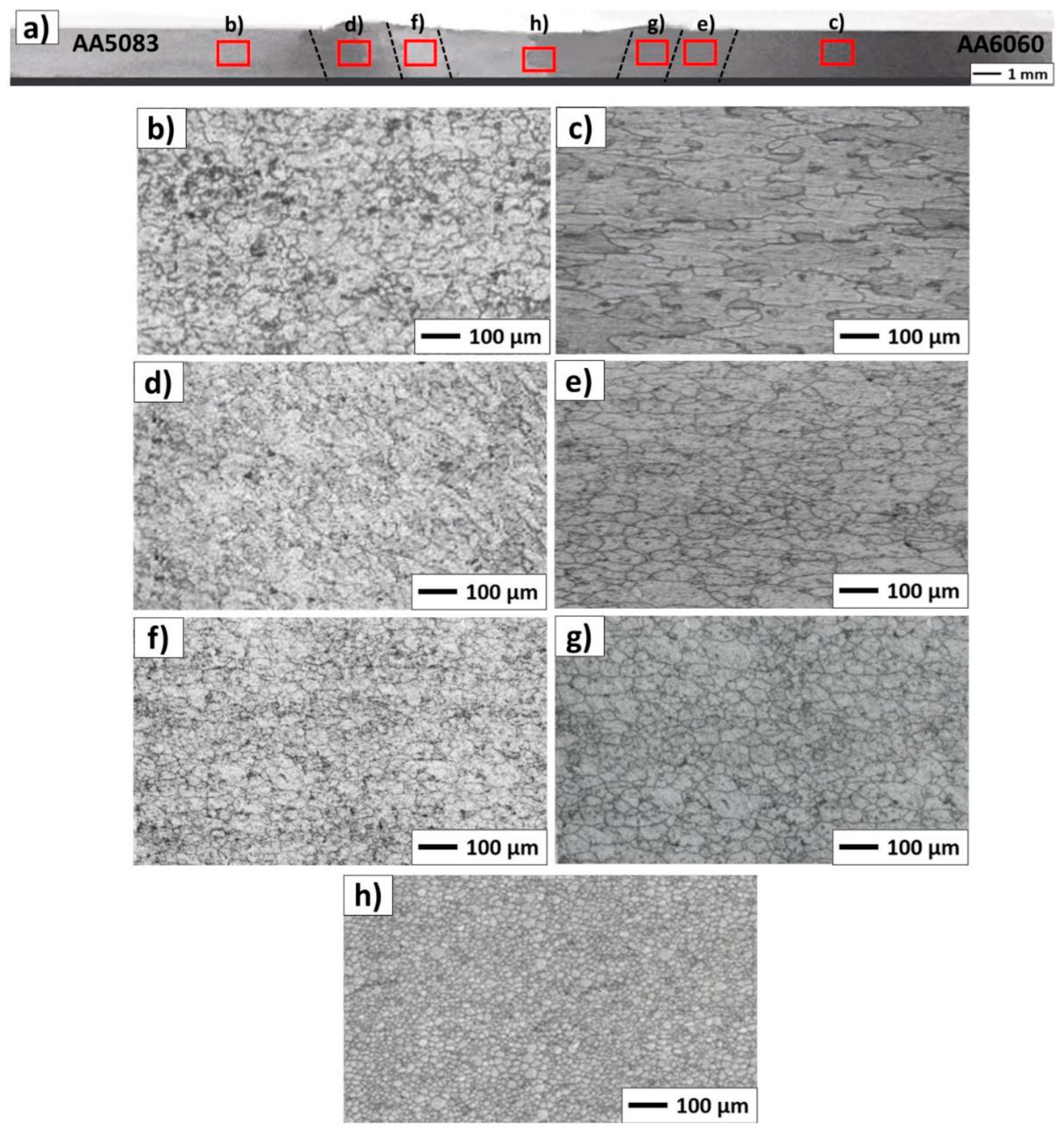
  131. Laska, A.; Szkodo, M.; Cavaliere, P.; Perrone, A. Influence of the Tool Rotational Speed on Physical and Chemical Properties of Dissimilar Friction-Stir-Welded AA5083/AA6060 Joints. Metals 2022, 12, 1658. [Google Scholar] [CrossRef]
  132. Ghaffarpour, M.; Kolahgar, S.; Dariani, B.M.; Dehghani, K. Evaluation of Dissimilar Welds of 5083-H12 and 6061-T6 Produced by Friction Stir Welding. Metall. Mater. Trans. A 2013, 44, 3697–3707. [Google Scholar] [CrossRef]
  133. Peel, M.J.; Steuwer, A.; Withers, P.J.; Dickerson, T.; Shi, Q.; Shercliff, H. Dissimilar Friction Stir Welds in AA5083-AA6082. Part I: Process Parameter Effects on Thermal History and Weld Properties. Metall. Mater. Trans. A 2006, 37, 2183–2193. [Google Scholar] [CrossRef]
  134. Devaiah, D.; Kishore, K.; Laxminarayana, P. Optimal FSW Process Parameters for Dissimilar Aluminium Alloys (AA5083 and AA6061) Using Taguchi Technique. Mater. Today Proc. 2018, 5, 4607–4614. [Google Scholar] [CrossRef]
  135. Palanivel, R.; Koshy Mathews, P.; Murugan, N.; Dinaharan, I. Effect of Tool Rotational Speed and Pin Profile on Microstructure and Tensile Strength of Dissimilar Friction Stir Welded AA5083-H111 and AA6351-T6 Aluminum Alloys. Mater. Des. 2012, 40, 7–16. [Google Scholar] [CrossRef]
  136. Goriparthi, V.; Nallu, R.; Chebolu, R.; Indupuri, S.; Rudrapati, R. Experimental Studies on Mechanical Behavior of TIG and Friction Stir Welded AA5083 -AA7075 Dissimilar Aluminum Alloys. Adv. Mater. Sci. Eng. 2023, 2023, 8622525. [Google Scholar] [CrossRef]
  137. Devaraju, A.; Jeshrun Shalem, M.; Manichandra, B. Effect of Rotation Speed on Tensile Properties & Microhardness of Dissimilar Al Alloys 6061-T6 to 2024 -T6 Welded via Solid State Joining Technique. Mater. Today Proc. 2019, 18, 3286–3290. [Google Scholar] [CrossRef]
  138. Das, U.; Toppo, V. Effect of Tool Rotational Speed on Temperature and Impact Strength of Friction Stir Welded Joint of Two Dissimilar Aluminum Alloys. Mater. Today Proc. 2018, 5, 6170–6175. [Google Scholar] [CrossRef]
  139. Das, U.; Das, R.; Toppo, V. Analysis of Some Mechanical Properties of Friction Stir Welded Joints of AA6101 and AA6351 Aluminum Alloys under T6 Condition. Mater. Today Proc. 2021, 44, 2700–2704. [Google Scholar] [CrossRef]
  140. Jamshidi Aval, H. Microstructure and Residual Stress Distributions in Friction Stir Welding of Dissimilar Aluminium Alloys. Mater. Des. 2015, 87, 405–413. [Google Scholar] [CrossRef]
  141. De Giorgi, M.; Scialpi, A.; Panella, F.W.; De Filippis, L.A.C. Effect of Shoulder Geometry on Residual Stress and Fatigue Properties of AA6082 Fsw Joints. J. Mech. Sci. Technol. 2009, 23, 26–35. [Google Scholar] [CrossRef]
  142. Richards, D.G.; Prangnell, P.B.; Withers, P.J.; Williams, S.W.; Nagy, T.; Morgan, S. Efficacy of Active Cooling for Controlling Residual Stresses in Friction Stir Welds. Sci. Technol. Weld. Join. 2010, 15, 156–165. [Google Scholar] [CrossRef]
  143. Campanelli, S.; Casalino, G.; Casavola, C.; Moramarco, V. Analysis and Comparison of Friction Stir Welding and Laser Assisted Friction Stir Welding of Aluminum Alloy. Materials 2013, 6, 5923–5941. [Google Scholar] [CrossRef] [PubMed] [Green Version]
  144. Haribalaji, V.; Boopathi, S.; Mohammed Asif, M. Optimization of Friction Stir Welding Process to Join Dissimilar AA2014 and AA7075 Aluminum Alloys. Mater. Today Proc. 2022, 50, 2227–2234. [Google Scholar] [CrossRef]
  145. Zuiko, I.S.; Malopheyev, S.; Mironov, S.; Kaibyshev, R. Dissimilar Friction Stir Welding of AA2519 and AA5182. Materials 2022, 15, 8776. [Google Scholar] [CrossRef]
  146. Tarkono, T.; Tenando, F.; Nafrizal, N.; Sukmana, I. The Effect of Rotational Speed on Friction Stir Welding (FSW) Quality of Dissimilar Aluminum Alloy Series AA 1100 and AA 5052. J. Polimesin 2023, 21, 21–24. [Google Scholar]
  147. Sivaselvan, S.; Natarajan, M.; Devadasan, S.R.; Sivaram, N.M. Influence of Friction Stir Welding Parameters on the Tribological Behavior of Dissimilar Aluminum Alloy Joint. Ind. Lubr. Tribol. 2023, 75, 197–203. [Google Scholar] [CrossRef]
  148. Heramo, W.T.; Workneh, H.Z. Optimization of Process Parameters in Friction Stir Welding of Dissimilar Aluminum Alloys (AA6061–T6 and AA5052–H32). Res. Sq. 2022, in press. [Google Scholar] [CrossRef]
  149. Wang, Z.; Zhu, W.; Zhang, Z.; Wang, B.; Xue, P.; Ni, D.; Liu, F.; Xiao, B.; Ma, Z.; Wang, F.; et al. Dissimilar Friction Stir Welding of 2219-T8 and 2195-T8 Aluminum Alloys: Part I—Microstructure Evolution and Mechanical Properties. J. Mater. Sci. 2023, 58, 9737–9754. [Google Scholar] [CrossRef]
  150. Ahmed, M.M.Z.; Ataya, S.; El-Sayed Seleman, M.M.; Mahdy, A.M.A.; Alsaleh, N.A.; Ahmed, E. Heat Input and Mechanical Properties Investigation of Friction Stir Welded AA5083/AA5754 and AA5083/AA7020. Metals 2020, 11, 68. [Google Scholar] [CrossRef]
  151. Palanivel, R.; Koshy Mathews, P.; Dinaharan, I.; Murugan, N. Mechanical and Metallurgical Properties of Dissimilar Friction Stir Welded AA5083-H111 and AA6351-T6 Aluminum Alloys. Trans. Nonferrous Met. Soc. China 2014, 24, 58–65. [Google Scholar] [CrossRef]
  152. Ghosh, M.; Husain, M.M.; Kumar, K.; Kailas, S.V. Friction Stir-Welded Dissimilar Aluminum Alloys: Microstructure, Mechanical Properties, and Physical State. J. Mater. Eng. Perform. 2013, 22, 3890–3901. [Google Scholar] [CrossRef]
  153. Devaiah, D.; Kishore, K.; Laxminarayana, P. Effect of Welding Speed on Mechanical Properties of Dissimilar Friction Stir Welded AA5083-H321 and AA6061-T6 Aluminum Alloys. Int. J. Adv. Eng. Res. Sci. 2017, 4, 22–28. [Google Scholar] [CrossRef]
  154. Jia, H.; Wu, K.; Sun, Y.; Hu, F.; Chen, G. Evaluation of Axial Force, Tool Torque and Weld Quality of Friction Stir Welded Dissimilar 6061/5083 Aluminum Alloys. CIRP J. Manuf. Sci. Technol. 2022, 37, 267–277. [Google Scholar] [CrossRef]
  155. Anandan, B.; Manikandan, M. Effect of Welding Speeds on the Metallurgical and Mechanical Property Characterization of Friction Stir Welding between Dissimilar Aerospace Grade 7050 T7651-2014A T6 Aluminium Alloys. Mater. Today Commun. 2023, 35, 106246. [Google Scholar] [CrossRef]
  156. Dimov, N.; Weisz-Patrault, D.; Tanguy, A.; Sapanathan, T.; Benoist, J.; Charkaluk, E.; Simar, A. Strain and Damage Analysis Using High Resolution Digital Image Correlation in the Stir Zone of an AA6061-AA7075 Dissimilar Friction Stir Weld. Mater. Today Commun. 2023, 34, 105359. [Google Scholar] [CrossRef]
  157. Khan, N.Z.; Bajaj, D.; Siddiquee, A.N.; Khan, Z.A.; Abidi, M.H.; Umer, U.; Alkhalefah, H. Investigation on Effect of Strain Rate and Heat Generation on Traverse Force in FSW of Dissimilar Aerospace Grade Aluminium Alloys. Materials 2019, 12, 1641. [Google Scholar] [CrossRef] [Green Version]
  158. Ahmed, M.M.Z.; Ataya, S.; El-Sayed Seleman, M.M.; Ammar, H.R.; Ahmed, E. Friction Stir Welding of Similar and Dissimilar AA7075 and AA5083. J. Mater. Process. Technol. 2017, 242, 77–91. [Google Scholar] [CrossRef]
  159. Alemdar, A.S.A.; Jalal, S.R.; Mulapeer, M.M.S. Influence of Friction Stir Welding Process on the Mechanical Characteristics of the Hybrid Joints AA2198-T8 to AA2024-T3. Adv. Mater. Sci. Eng. 2022, 2022, 7055446. [Google Scholar] [CrossRef]
  160. Barbini, A.; Carstensen, J.; Dos Santos, J.F. Influence of Alloys Position, Rolling and Welding Directions on Properties of AA2024/AA7050 Dissimilar Butt Weld Obtained by Friction Stir Welding. Metals 2018, 8, 202. [Google Scholar] [CrossRef] [Green Version]
  161. Cavaliere, P.; De Santis, A.; Panella, F.; Squillace, A. Effect of Welding Parameters on Mechanical and Microstructural Properties of Dissimilar AA6082–AA2024 Joints Produced by Friction Stir Welding. Mater. Des. 2009, 30, 609–616. [Google Scholar] [CrossRef]
  162. Niu, P.; Li, W.; Yang, C.; Chen, Y.; Chen, D. Low Cycle Fatigue Properties of Friction Stir Welded Dissimilar 2024-to-7075 Aluminum Alloy Joints. Mater. Sci. Eng. A 2022, 832, 142423. [Google Scholar] [CrossRef]
  163. Cole, E.G.; Fehrenbacher, A.; Duffie, N.A.; Zinn, M.R.; Pfefferkorn, F.E.; Ferrier, N.J. Weld Temperature Effects during Friction Stir Welding of Dissimilar Aluminum Alloys 6061-T6 and 7075-T6. Int. J. Adv. Manuf. Technol. 2014, 71, 643–652. [Google Scholar] [CrossRef]
  164. Yan, Z.; Liu, X.; Fang, H. Effect of Sheet Configuration on Microstructure and Mechanical Behaviors of Dissimilar Al–Mg–Si/Al–Zn–Mg Aluminum Alloys Friction Stir Welding Joints. J. Mater. Sci. Technol. 2016, 32, 1378–1385. [Google Scholar] [CrossRef]
  165. Schmale, J.; Fehrenbacher, A.; Shrivastava, A.; Pfefferkorn, F.E. Calibration of Dynamic Tool–Workpiece Interface Temperature Measurement during Friction Stir Welding. Measurement 2016, 88, 331–342. [Google Scholar] [CrossRef] [Green Version]
  166. Simar, A.; Jonckheere, C.; Deplus, K.; Pardoen, T.; de Meester, B. Comparing Similar and Dissimilar Friction Stir Welds of 2017–6005A Aluminium Alloys. Sci. Technol. Weld. Join. 2010, 15, 254–259. [Google Scholar] [CrossRef]
  167. Kim, N.-K.; Kim, B.-C.; An, Y.-G.; Jung, B.-H.; Song, S.-W.; Kang, C.-Y. The Effect of Material Arrangement on Mechanical Properties in Friction Stir Welded Dissimilar A5052/A5J32 Aluminum Alloys. Met. Mater. Int. 2009, 15, 671–675. [Google Scholar] [CrossRef]
  168. Donatus, U.; Thompson, G.E.; Zhou, X.; Wang, J.; Beamish, K. Flow Patterns in Friction Stir Welds of AA5083 and AA6082 Alloys. Mater. Des. 2015, 83, 203–213. [Google Scholar] [CrossRef]
  169. Zhao, Z.; Liang, H.; Zhao, Y.; Yan, K. Effect of Exchanging Advancing and Retreating Side Materials on Mechanical Properties and Electrochemical Corrosion Resistance of Dissimilar 6013-T4 and 7003 Aluminum Alloys FSW Joints. J. Mater. Eng. Perform. 2018, 27, 1777–1783. [Google Scholar] [CrossRef]
  170. Park, S.-K.; Hong, S.-T.; Park, J.-H.; Park, K.-Y.; Kwon, Y.-J.; Son, H.-J. Effect of Material Locations on Properties of Friction Stir Welding Joints of Dissimilar Aluminium Alloys. Sci. Technol. Weld. Join. 2010, 15, 331–336. [Google Scholar] [CrossRef]
  171. Hong, S.-T. Mixing of materials in FSW of dissimilar aluminum alloys. Trans. Korean. Soc. Mech. Eng. A 2009, 33, 108–113. [Google Scholar] [CrossRef]
  172. Niu, P.L.; Li, W.Y.; Li, N.; Xu, Y.X.; Chen, D.L. Exfoliation Corrosion of Friction Stir Welded Dissimilar 2024-to-7075 Aluminum Alloys. Mater. Charact. 2019, 147, 93–100. [Google Scholar] [CrossRef]
  173. Sindhuja, M.; Neelakrishnan, S.; Davidson, B.S. Effect of Welding Parameters on Mechanical Properties of Friction Stir Welding of Dissimilar Metals—A Review. IOP Conf. Ser. Mater. Sci. Eng. 2021, 1185, 012019. [Google Scholar] [CrossRef]
  174. Prasanth, R.S.S.; Hans Raj, K. Determination of Optimal Process Parameters of Friction Stir Welding to Join Dissimilar Aluminum Alloys Using Artificial Bee Colony Algorithm. Trans. Indian Inst. Met. 2018, 71, 453–462. [Google Scholar] [CrossRef]
  175. Palanivel, R.; Koshy Mathews, P.; Murugan, N. Optimization of Process Parameters to Maximize Ultimate Tensile Strength of Friction Stir Welded Dissimilar Aluminum Alloys Using Response Surface Methodology. J. Cent. South Univ. 2013, 20, 2929–2938. [Google Scholar] [CrossRef]
  176. Ramamoorthi, R.; Yuvaraj, K.P.; Gokul, C.; Eashwar, S.J.; Arunkumar, N.; Abith Tamil Dheen, S. An Investigation of the Impact of Axial Force on Friction Stir-Welded AA5086/AA6063 on Microstructure and Mechanical Properties Butt Joints. Mater. Today Proc. 2021, 37, 3159–3163. [Google Scholar] [CrossRef]
  177. de Caetano, G.Q.; Silva, C.C.; Motta, M.F.; Miranda, H.C.; Farias, J.P.; Bergmann, L.A.; dos Santos, J.F. Influence of Rotation Speed and Axial Force on the Friction Stir Welding of AISI 410S Ferritic Stainless Steel. J. Mater. Process. Technol. 2018, 262, 430–436. [Google Scholar] [CrossRef]
  178. Srinivasan, R.; Ramesh, A.; Athithanambi, A. Effect of Axial Force on Microstructure and Mechanical Properties of Friction Stir Welded Squeeze Cast A413 Aluminium Alloy. Mater. Today Proc. 2018, 5, 13486–13494. [Google Scholar] [CrossRef]
  179. Venu, B.; BhavyaSwathi, I.; Raju, L.S.; Santhanam, G. A Review on Friction Stir Welding of Various Metals and Its Variables. Mater. Today Proc. 2019, 18, 298–302. [Google Scholar] [CrossRef]
  180. Elangovan, K.; Balasubramanian, V.; Valliappan, M. Influences of Tool Pin Profile and Axial Force on the Formation of Friction Stir Processing Zone in AA6061 Aluminium Alloy. Int. J. Adv. Manuf. Technol. 2008, 38, 285–295. [Google Scholar] [CrossRef]
  181. Jayaraman, M.; Sivasubramanian, R.; Balasubramanian, V.; Babu, S. Influences of Process Parameters on Tensile Strength of Friction Stir Welded Cast A319 Aluminium Alloy Joints. Met. Mater. Int. 2009, 15, 313–320. [Google Scholar] [CrossRef]
  182. Palanivel, R.; Mathews, P.K.; Balakrishnan, M.; Dinaharan, I.; Murugan, N. Effect of Tool Pin Profile and Axial Force on Tensile Behavior in Friction Stir Welding of Dissimilar Aluminum Alloys. Adv. Mater. Res. 2011, 415–417, 1140–1146. [Google Scholar] [CrossRef]
  183. Peng, C.; Jing, C.; Siyi, Q.; Siqi, Z.; Shoubo, S.; Ting, J.; Zhiqing, Z.; Zhihong, J.; Qing, L. Friction Stir Welding Joints of 2195-T8 Al–Li Alloys: Correlation of Temperature Evolution, Microstructure and Mechanical Properties. Mater. Sci. Eng. A 2021, 823, 141501. [Google Scholar] [CrossRef]
  184. Xue, F.; He, D.; Zhou, H. Effect of Ultrasonic Vibration in Friction Stir Welding of 2219 Aluminum Alloy: An Effective Model for Predicting Weld Strength. Metals 2022, 12, 1101. [Google Scholar] [CrossRef]
  185. Dewan, M.W.; Huggett, D.J.; Warren Liao, T.; Wahab, M.A.; Okeil, A.M. Prediction of Tensile Strength of Friction Stir Weld Joints with Adaptive Neuro-Fuzzy Inference System (ANFIS) and Neural Network. Mater. Des. 2016, 92, 288–299. [Google Scholar] [CrossRef] [Green Version]
  186. Yin, L.; Wang, J.; Hu, H.; Han, S.; Zhang, Y. Prediction of Weld Formation in 5083 Aluminum Alloy by Twin-Wire CMT Welding Based on Deep Learning. Weld. World 2019, 63, 947–955. [Google Scholar] [CrossRef]
  187. Agelet De Saracibar, C. Challenges to Be Tackled in the Computational Modeling and Numerical Simulation of FSW Processes. Metals 2019, 9, 573. [Google Scholar] [CrossRef] [Green Version]
  188. Meyghani, B.; Awang, M.; Wu, C.S. Finite Element Modeling of Friction Stir Welding (FSW) on a Complex Curved Plate. J. Adv. Join. Process. 2020, 1, 100007. [Google Scholar] [CrossRef]
  189. Meyghani, B.; Awang, M.B. Prediction of the Temperature Distribution During Friction Stir Welding (Fsw) with A Complex Curved Welding Seam: Application In The Automotive Industry. MATEC Web Conf. 2018, 225, 01001. [Google Scholar] [CrossRef]
  190. Luesak, P.; Pitakaso, R.; Sethanan, K.; Golinska-Dawson, P.; Srichok, T.; Chokanat, P. Multi-Objective Modified Differential Evolution Methods for the Optimal Parameters of Aluminum Friction Stir Welding Processes of AA6061-T6 and AA5083-H112. Metals 2023, 13, 252. [Google Scholar] [CrossRef]
  191. Kalil Rahiman, M.; Santhoshkumar, S.; Mythili, S.; Barkavi, G.E.; Velmurugan, G.; Sundarakannan, R. Experimental Analysis of Friction Stir Welded of Dissimilar Aluminium 6061 and Titanium TC4 Alloys Using Response Surface Methodology (RSM). Mater. Today Proc. 2022, 66, 1016–1022. [Google Scholar] [CrossRef]
  192. Kavitha, M.; Manickavasagam, V.M.; Sathish, T.; Gugulothu, B.; Sathish Kumar, A.; Karthikeyan, S.; Subbiah, R. Parameters Optimization of Dissimilar Friction Stir Welding for AA7079 and AA8050 through RSM. Adv. Mater. Sci. Eng. 2021, 2021, 9723699. [Google Scholar] [CrossRef]
  193. Kumar, P.; Kadiyan, S.; Kumar, R. Optimization of Process Parameters of Friction Stir Welded Joint of Dissimilar Aluminum Alloy by Response Surface Methodology. Int. J. Res. Eng. Innov. 2022, 6, 236–244. [Google Scholar]
  194. Jain, S.; Sharma, N.; Gupta, R. Dissimilar Alloys (AA6082/AA5083) Joining by FSW and Parametric Optimization Using Taguchi, Grey Relational and Weight Method. Eng. Solid Mech. 2018, 6, 51–66. [Google Scholar] [CrossRef]
  195. Koilraj, M.; Sundareswaran, V.; Vijayan, S.; Koteswara Rao, S.R. Friction Stir Welding of Dissimilar Aluminum Alloys AA2219 to AA5083—Optimization of Process Parameters Using Taguchi Technique. Mater. Des. 2012, 42, 1–7. [Google Scholar] [CrossRef]
  196. Abd Elnabi, M.M.; El Mokadem, A.; Osman, T. Optimization of Process Parameters for Friction Stir Welding of Dissimilar Aluminum Alloys Using Different Taguchi Arrays. Int. J. Adv. Manuf. Technol. 2022, 121, 3935–3964. [Google Scholar] [CrossRef]
  197. Asmare, A.; Al-Sabur, R.; Messele, E. Experimental Investigation of Friction Stir Welding on 6061-T6 Aluminum Alloy Using Taguchi-Based GRA. Metals 2020, 10, 1480. [Google Scholar] [CrossRef]
  198. Prasad, M.V.R.D.; kumar Namala, K. Process Parameters Optimization in Friction Stir Welding by ANOVA. Mater. Today Proc. 2018, 5, 4824–4831. [Google Scholar] [CrossRef]
  199. Raja, R.; Parthiban, A.; Nandha Gopan, S.; Degefa, D. Investigate the Process Parameter on the Friction Stir Welding of Dissimilar Aluminium Alloys. Adv. Mater. Sci. Eng. 2022, 2022, 4980291. [Google Scholar] [CrossRef]
  200. Salloomi, K.N.; Shammari, A.Z.M.; Ahmed, S.H. Evaluation of FSW Process Parameters of Dissimilar Aluminium Alloys. Innov. Syst. Des. Eng. 2016, 7, 55–69. [Google Scholar]
  201. Shojaeefard, M.H.; Khalkhali, A.; Akbari, M.; Asadi, P. Investigation of Friction Stir Welding Tool Parameters Using FEM and Neural Network. Proc. Inst. Mech. Eng. Part L J. Mater. Des. Appl. 2015, 229, 209–217. [Google Scholar] [CrossRef]
  202. Yu, F.; Zhao, Y.; Lin, Z.; Miao, Y.; Zhao, F.; Xie, Y. Prediction of Mechanical Properties and Optimization of Friction Stir Welded 2195 Aluminum Alloy Based on BP Neural Network. Metals 2023, 13, 267. [Google Scholar] [CrossRef]
  203. Elatharasan, G.; Kumar, V.S.S. Modelling and Optimization of Friction Stir Welding Parameters for Dissimilar Aluminium Alloys Using RSM. Procedia Eng. 2012, 38, 3477–3481. [Google Scholar] [CrossRef] [Green Version]
  204. Nait Salah, A.; Mehdi, H.; Mehmood, A.; Wahab Hashmi, A.; Malla, C.; Kumar, R. Optimization of Process Parameters of Friction Stir Welded Joints of Dissimilar Aluminum Alloys AA3003 and AA6061 by RSM. Mater. Today Proc. 2022, 56, 1675–1683. [Google Scholar] [CrossRef]
  205. Suhin, S.; Robin Divahar, S.; Edwin Raja Dhas, J.; Anton Savio Lewise, K.; Satyanarayana Gupta, M. Optimizing FSW Process Parameters Using RSM and Regression Analysis for Similar and Dissimilar Aluminium Materials. Mater. Today Proc. 2022, 64, 368–373. [Google Scholar] [CrossRef]
  206. Harachai, K.; Prasomthong, S. Investigation of the Optimal Parameters for Butt Joints in a Friction Stir Welding (FSW) Process with Dissimilar Aluminium Alloys. Mater. Res. Express 2023, 10, 026514. [Google Scholar] [CrossRef]
  207. Umamaheswarrao, P. Desirability Function Analysis Based Multi Response Optimization of Process Parameters during Friction Stir Welding of AA6061-AA7075. INCAS Bull. 2023, 15, 121–131. [Google Scholar] [CrossRef]
  208. Singaravel, B.; Chakradhar, B.; Soundar Rajan, D.; Kiran Kumar, A. Optimization of Friction Stir Welding Process Parameters Using MCDM Method. Mater. Today Proc. 2023, 76, 597–601. [Google Scholar] [CrossRef]
  209. Umamaheswarrao, P. Multi-Response Optimization of Process Parameters during Friction Stir Welding of AA2014-AA7075 Using TOPSIS Approach. INCAS Bull. 2023, 15, 107–117. [Google Scholar] [CrossRef]
  210. Akbari, M.; Asadi, P.; Besharati Givi, M.K.; Khodabandehlouie, G. Artificial Neural Network and Optimization. In Advances in Friction-Stir Welding and Processing; Elsevier: Amsterdam, The Netherlands, 2014; pp. 543–599. [Google Scholar]
  211. Arya, H.K.; Jaiswal, D. Study on Friction Stir Welding of Aluminium Plates Using an Artificial Neural Network. Turk. J. Comput. Math. Educ. 2021, 12, 5828–5835. [Google Scholar]
  212. Essa, A.R.S.; Ahmed, M.M.Z.; Aboud, A.R.K.; Alyamani, R.; Sebaey, T.A. Prediction of Tool Eccentricity Effects on the Mechanical Properties of Friction Stir Welded AA5754-H24 Aluminum Alloy Using ANN Model. Materials 2023, 16, 3777. [Google Scholar] [CrossRef] [PubMed]
  213. Okuyucu, H.; Kurt, A.; Arcaklioglu, E. Artificial Neural Network Application to the Friction Stir Welding of Aluminum Plates. Mater. Des. 2007, 28, 78–84. [Google Scholar] [CrossRef]
  214. Gupta, S.K.; Pandey, K.; Kumar, R. Artificial Intelligence-Based Modelling and Multi-Objective Optimization of Friction Stir Welding of Dissimilar AA5083-O and AA6063-T6 Aluminium Alloys. Proc. Inst. Mech. Eng. Part L J. Mater. Des. Appl. 2018, 232, 333–342. [Google Scholar] [CrossRef]
  215. Shojaeefard, M.H.; Behnagh, R.A.; Akbari, M.; Givi, M.K.B.; Farhani, F. Modelling and Pareto Optimization of Mechanical Properties of Friction Stir Welded AA7075/AA5083 Butt Joints Using Neural Network and Particle Swarm Algorithm. Mater. Des. 2013, 44, 190–198. [Google Scholar] [CrossRef]
  216. Kraiklang, R.; Chueadee, C.; Jirasirilerd, G.; Sirirak, W.; Gonwirat, S. A Multiple Response Prediction Model for Dissimilar AA-5083 and AA-6061 Friction Stir Welding Using a Combination of AMIS and Machine Learning. Computation 2023, 11, 100. [Google Scholar] [CrossRef]
  217. Elsheikh, A.H. Applications of Machine Learning in Friction Stir Welding: Prediction of Joint Properties, Real-Time Control and Tool Failure Diagnosis. Eng. Appl. Artif. Intell. 2023, 121, 105961. [Google Scholar] [CrossRef]
  218. Insua, P.; Nakkiew, W.; Wisittipanich, W. Post Weld Heat Treatment Optimization of Dissimilar Friction Stir Welded AA2024-T3 and AA7075-T651 Using Machine Learning and Metaheuristics. Materials 2023, 16, 2081. [Google Scholar] [CrossRef]
  219. Moradi, M.M.; Jamshidi Aval, H.; Jamaati, R. Microstructure and Mechanical Properties in Nano and Microscale SiC-Included Dissimilar Friction Stir Welding of AA6061-AA2024. Mater. Sci. Technol. 2018, 34, 388–401. [Google Scholar] [CrossRef]
  220. Verma, S.; Msomi, V.; Mabuwa, S.; Merdji, A.; Misra, J.P.; Batra, U.; Sharma, S. Machine Learning Application for Evaluating the Friction Stir Processing Behavior of Dissimilar Aluminium Alloys Joint. Proc. Inst. Mech. Eng. Part L J. Mater. Des. Appl. 2021, 236, 633–646. [Google Scholar] [CrossRef]
  221. Chiaranai, S.; Pitakaso, R.; Sethanan, K.; Kosacka-Olejnik, M.; Srichok, T.; Chokanat, P. Ensemble Deep Learning Ultimate Tensile Strength Classification Model for Weld Seam of Asymmetric Friction Stir Welding. Processes 2023, 11, 434. [Google Scholar] [CrossRef]
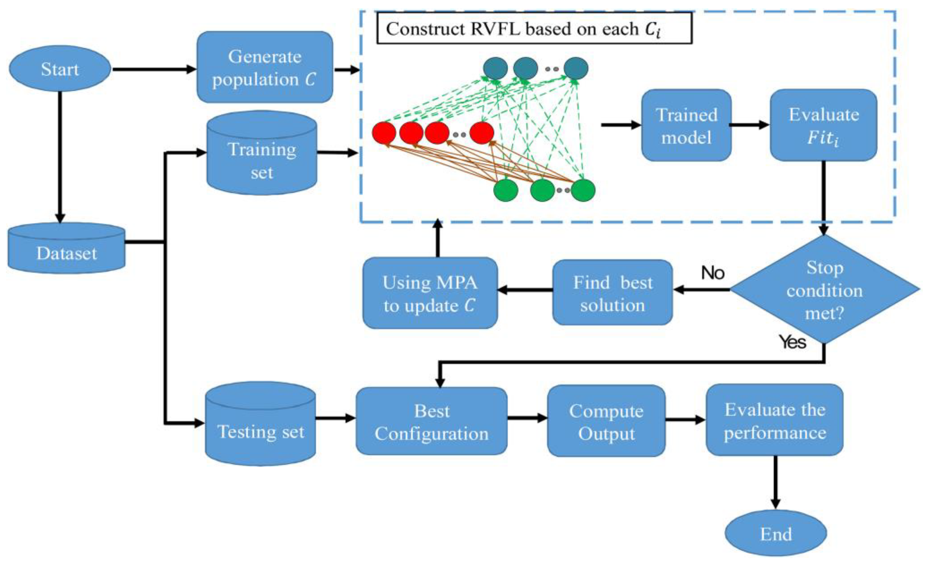
  222. Abd Elaziz, M.; Shehabeldeen, T.A.; Elsheikh, A.H.; Zhou, J.; Ewees, A.A.; Al-qaness, M.A.A. Utilization of Random Vector Functional Link Integrated with Marine Predators Algorithm for Tensile Behavior Prediction of Dissimilar Friction Stir Welded Aluminum Alloy Joints. J. Mater. Res. Technol. 2020, 9, 11370–11381. [Google Scholar] [CrossRef]
  223. Gupta, S.K.; Pandey, K.N.; Kumar, R. Experimental Modelling and Genetic Algorithm-Based Optimisation of Friction Stir Welding Process Parameters for Joining of Dissimilar AA5083-O and AA6063-T6 Aluminium Alloys. Int. J. Mater. Prod. Technol. 2018, 56, 253–270. [Google Scholar] [CrossRef]
  224. Yunus, M.; Alsoufi, M.S. Mathematical Modelling of a Friction Stir Welding Process to Predict the Joint Strength of Two Dissimilar Aluminium Alloys Using Experimental Data and Genetic Programming. Model. Simul. Eng. 2018, 2018, 4183816. [Google Scholar] [CrossRef]
  225. Hossfeld, M. Modeling Friction Stir Welding: On Prediction and Numerical Tool Development. Metals 2022, 12, 1432. [Google Scholar] [CrossRef]
  226. Sen, S.; Murugesan, J. Experimental and Numerical Analysis of Friction Stir Welding: A Review. Eng. Res. Express 2022, 4, 032004. [Google Scholar] [CrossRef]
  227. Eivani, A.R.; Vafaeenezhad, H.; Jafarian, H.R.; Zhou, J. A Novel Approach to Determine Residual Stress Field during FSW of AZ91 Mg Alloy Using Combined Smoothed Particle Hydrodynamics/Neuro-Fuzzy Computations and Ultrasonic Testing. J. Magnes. Alloys 2021, 9, 1304–1328. [Google Scholar] [CrossRef]
  228. Malik, V.; Sanjeev, N.K.; Bajakke, P. Review on Modelling of Friction Stir Welding Using Finite Element Approach and Significance of Formulations in Simulation. Int. J. Manuf. Res. 2020, 15, 107–135. [Google Scholar] [CrossRef]
  229. Das, D.; Bag, S.; Pal, S. Probing Finite Element Modelling of Defects in Friction Stir Welding by Tailoring Mass Scaling Factor. Mater. Today Commun. 2023, 35, 105646. [Google Scholar] [CrossRef]
  230. Saha, R.; Biswas, P. Thermomechanical Analysis of Induction Assisted Friction Stir Welding of Inconel 718 Alloy: A Finite Element Approach. Int. J. Press. Vessel. Pip. 2022, 199, 104731. [Google Scholar] [CrossRef]
  231. Meyghani, B.; Awang, M.; Emamian, S.S.; Mohd Nor, M.K.; Pedapati, S.R. A Comparison of Different Finite Element Methods in the Thermal Analysis of Friction Stir Welding (FSW). Metals 2017, 7, 450. [Google Scholar] [CrossRef] [Green Version]
  232. Kubit, A.; Trzepiecinski, T. A Fully Coupled Thermo-Mechanical Numerical Modelling of the Refill Friction Stir Spot Welding Process in Alclad 7075-T6 Aluminium Alloy Sheets. Arch. Civ. Mech. Eng. 2020, 20, 117. [Google Scholar] [CrossRef]
  233. Ambrosio, D.; Tongne, A.; Wagner, V.; Dessein, G.; Cahuc, O. A new damage evolution criterion for the coupled Eulerian-Lagrangian approach: Application to three-dimensional numerical simulation of segmented chip formation mechanisms in orthogonal cutting. J. Manuf. Process. 2022, 73, 149–163. [Google Scholar] [CrossRef]
  234. Das, D.; Bag, S.; Pal, S.; Sharma, A. Material Defects in Friction Stir Welding through Thermo–Mechanical Simulation: Dissimilar Materials with Tool Wear Consideration. Materials 2022, 16, 301. [Google Scholar] [CrossRef] [PubMed]
  235. Ambrosio, D.; Tongne, A.; Wagner, V.; Dessein, G.; Cahuc, O. Towards Material Flow Prediction in Friction Stir Welding Accounting for Mechanisms Governing Chip Formation in Orthogonal Cutting. J. Manuf. Process. 2023, 85, 450–465. [Google Scholar] [CrossRef]
  236. Shash, A.Y.; El-Moayed, M.H.; Abd Rabou, M.; El-Sherbiny, M.G. A Coupled Experimental and Numerical Analysis of AA6063 Friction Stir Welding. Proc. Inst. Mech. Eng. C J. Mech. Eng. Sci. 2022, 236, 8392–8400. [Google Scholar] [CrossRef]
  237. Meyghani, B.; Awang, M.; Emamian, S. A Comparative Study of Finite Element Analysis for Friction Stir Welding Application. ARPN J. Eng. Appl. Sci. 2016, 11, 12984–12989. [Google Scholar]
  238. Buffa, G.; Hua, J.; Shivpuri, R.; Fratini, L. Design of the Friction Stir Welding Tool Using the Continuum Based FEM Model. Mater. Sci. Eng. A 2006, 419, 381–388. [Google Scholar] [CrossRef]
  239. Sibalic, N.; Vukcevic, M. Numerical Simulation for FSW Process at Welding Aluminium Alloy AA6082-T6. Metals 2019, 9, 747. [Google Scholar] [CrossRef] [Green Version]
  240. Zahari, S.N.; Mohd Sani, M.S.; Ishak, M. Finite Element Modelling and Updating of Friction Stir Welding (FSW) Joint for Vibration Analysis. MATEC Web Conf. 2017, 90, 01021. [Google Scholar] [CrossRef] [Green Version]
  241. Sivasankara Raju, R.; Jagadish; Rao, C.; Kumar Aadapa, S.; Yanda, S. Predication of Temperature Distribution and Strain during FSW of Dissimilar Aluminum Alloys Using Deform 3D. Mater. Today Proc. 2022, 59, 1760–1767. [Google Scholar] [CrossRef]
  242. Salloomi, K.N.; Al-Sumaidae, S. Coupled Eulerian–Lagrangian Prediction of Thermal and Residual Stress Environments in Dissimilar Friction Stir Welding of Aluminum Alloys. J. Adv. Join. Process. 2021, 3, 100052. [Google Scholar] [CrossRef]
  243. Al-Badour, F.; Merah, N.; Shuaib, A.; Bazoune, A. Thermo-Mechanical Finite Element Model of Friction Stir Welding of Dissimilar Alloys. Int. J. Adv. Manuf. Technol. 2014, 72, 607–617. [Google Scholar] [CrossRef]
  244. Karash, E.T.; Ali, H.M.; Hamid, A.F. Mathematical Model for the Temperature Distribution on The Surface of Two Aluminum Alloys Welded by Friction Stir Welding. Ann. “Dunarea de Jos” Univ. Galati Fascicle XII Weld. Equip. Technol. 2022, 33, 47–58. [Google Scholar] [CrossRef]
  245. Nagathil, R.; Hou, G.; Demuren, A.; Williamson, K. Modeling Experience on Friction Stir Welding Using FLUENT; SAE International: Warrendale, PA, USA, 2005. [Google Scholar]
  246. Wang, X.; Xiao, Y.; Shi, L.; Zhai, M.; Wu, C.; Chen, G. Revealing the Mechanism of Tool Tilting on Suppressing the Formation of Void Defects in Friction Stir Welding. J. Mater. Res. Technol. 2023, 25, 38–54. [Google Scholar] [CrossRef]
  247. Ji, H.; Deng, Y.L.; Xu, H.Y.; Yin, X.; Zhang, T.; Wang, W.Q.; Dong, H.G.; Wang, T.Y.; Wu, J.P. Numerical Modeling for the Mechanism of Shoulder and Pin Features Affecting Thermal and Material Flow Behavior in Friction Stir Welding. J. Mater. Res. Technol. 2022, 21, 662–678. [Google Scholar] [CrossRef]
  248. Chen, J.; Wang, X.; Shi, L.; Wu, C.; Liu, H.; Chen, G. Numerical Simulation of Weld Formation in Friction Stir Welding Based on Non-Uniform Tool-Workpiece Interaction: An Effect of Tool Pin Size. J. Manuf. Process. 2023, 86, 85–97. [Google Scholar] [CrossRef]
  249. Tang, J.; Shen, Y. Numerical Simulation and Experimental Investigation of Friction Stir Lap Welding between Aluminum Alloys AA2024 and AA7075. J. Alloys Compd. 2016, 666, 493–500. [Google Scholar] [CrossRef]
  250. Padmanaban, R.; Kishore, V.R.; Balusamy, V. Numerical Simulation of Temperature Distribution and Material Flow During Friction Stir Welding of Dissimilar Aluminum Alloys. Procedia Eng. 2014, 97, 854–863. [Google Scholar] [CrossRef] [Green Version]
Figure 1. Main process parameters.
Metals 13 01176 g001
Figure 2. Typical cross section of a friction stir welded joint: (a) Unaffected material; (b) Heat-affected zone (HAZ); (c) Thermomechanically affected zone (TMAZ); (d) Weld nugget o Stirring zone (SZ).
Metals 13 01176 g002
Figure 3. Typical defects in dissimilar aluminum friction stir welded joints [96].
Metals 13 01176 g003
Figure 4. Smooth and perfect welding.
Metals 13 01176 g004
Figure 5. Distribution of heat flux before (a) and after (b) applying the tilt angle [112].
Metals 13 01176 g005
Figure 6. Macrostructure of the weld produced with a tool rotational speed of 1200 rpm (a) and microstructures of base metals AA5083 (b), AA6060 (c), HAZ on AA5083 side (d), HAZ on AA6060 side (e), TMAZ on AA5083 side (f), TMAZ on AA6060 side (g) and the weld nugget (h) [131].
Metals 13 01176 g006
Figure 7. Cross-sections of friction stir welded joints at different rotational and traverse speeds for AA5083/AA7020 and AA7020/AA5083 after etching: (a,d) 500 rpm, 20 mm/min, (b,e) 500 rpm, 40 mm/min and (c,f) 500 rpm, 80 mm/min [150].
Metals 13 01176 g007
Figure 8. Optimal rotational speed/welding speed combinations.
Metals 13 01176 g008
Figure 9. The framework of MPA-RVFL [222].
Metals 13 01176 g009
Figure 10. Effects of FSW parameters on tensile strength; (a) rotational speed and pin profile, (b) welding speed and pin profile, and (c) tool axial force and pin profile [222].
Metals 13 01176 g010
Figure 11. Temperature isosurface contours when full plunge was achieved: (a) 550 rpm, (b) 950 rpm [242].
Metals 13 01176 g011
Figure 12. Temperature contours on transverse section for welding speed of (a) 20 mm/min, (b) 40 mm/min and (c) 60 mm/min (shoulder diameter = 17.5 mm, rotational speed = 900 rpm) [250].
Metals 13 01176 g012
Figure 13. Temperature contours on transverse section: (a) 900 rpm, (b) 1050 rpm and (c) 1200 rpm (welding speed = 20 mm/min, shoulder diameter = 17.5 mm) [250].
Metals 13 01176 g013
Table 1. Typical pin geometries (adapted from [72]).
Outer SurfaceEnd Surface
CylindricalSmooth cylinderCircleMetals 13 01176 i001
Fluted cylinderThree sidedMetals 13 01176 i002
Four sidedMetals 13 01176 i003
Cylinder with flatsTriangleMetals 13 01176 i004
SquareMetals 13 01176 i005
HexagonalMetals 13 01176 i006
Threaded cylinderCircleMetals 13 01176 i007
Threaded and fluted cylinderThree sidedMetals 13 01176 i008
Four sidedMetals 13 01176 i009
Threaded and flat cylinderTriangleMetals 13 01176 i010
SquareMetals 13 01176 i011
HexagonalMetals 13 01176 i012
TaperedSmooth CircleMetals 13 01176 i013
Fluted Three sidedMetals 13 01176 i014
Four sidedMetals 13 01176 i015
Taper with flatsTriangleMetals 13 01176 i016
SquareMetals 13 01176 i017
HexagonalMetals 13 01176 i018
ThreadedCircleMetals 13 01176 i019
Threaded with flutedThree sidedMetals 13 01176 i020
Four sidedMetals 13 01176 i021
Threaded with flatTriangleMetals 13 01176 i022
SquareMetals 13 01176 i023
HexagonalMetals 13 01176 i024
Table 2. Typical shoulder geometries (adapted from [86,87]).
FeatureScheme
ScrolledMetals 13 01176 i025
KnurledMetals 13 01176 i026
RidgedMetals 13 01176 i027
GroovedMetals 13 01176 i028
Concentric CirclesMetals 13 01176 i029
Table 3. Effect of tool shoulder and pin geometry.
Ref.Sheet
Material
Sheet
Position
AS/RS
Pin ProfileTilt
Angle (°)
Rotational Speed (rpm)Welding Speed
(mm/min)
Axial Force (kN)Main Results
[110]2017-T6
6061-T6
-Straight hexagonal
Straight pentagonal
Straight cylindrical
Straight square
Taper square
0160032-Straight square tool pin profile produces better metallurgical and mechanical properties. The properties are inferior to those of other pin profiles, but it is preferred because the related joint is defect-free.
[107]2024-T365
5083-H111
-Square
Triangular
Stepped
-90016-Square pin produces a good metal flow and, consequently, a good stirring.
[99]2024-O
6061-T6
-Cylindrical
Stepped
-900
1400
1800
--Cylindrical profile—at 1400 rpm—promotes the material flow.
[91]2024-T351
7075-T651
-Flute radii:
0, 2, 3, 6, ∞ mm
-900150-Radius equal to that of the pin leads to the strongest joint.
[93]5052-H32
6061-T6
AS
RS
Taper cylinder
Threaded cylinder
-90060-Taper pin profile leads to a fine grain microstructure.
[97]5083-H111
AA6061-T6
-Straight square
Threaded cylinder
Tapered cylinder
----Straight square shows better mechanical properties.
[88]5083-O
6061-T6
-Square cylinder
Straight cylinder
Tapered cylinder
1.11156839.53-Straight cylinder tool guarantees higher weld quality.
[89]5083
6351
-Partial impeller
Full impeller
Flat grove
----Full impeller generates enhanced material flow.
[111]5083
7068
-Straight cylindrical
Taper cylindrical
Triangular tool
-800
1000
1200
1400
30
40
50
60
3
4
5
6
The triangular tool offers the maximum tensile strength and microhardness of the investigation with the combination 1200 rpm/30 mm/min/3 kN.
[73]5083-H111
7075-T651
RS
AS
Triflute
Tapered with a thread
-140
280
355
450
560
900
14026.4Triflute pin—at 280 rpm—guarantees the higher tensile properties and a defect-free joint with a wider stir zone.
[90]5083
7075
-Threaded straight cylindrical,
Tapered cylindrical,
Threaded tapered cylindrical
-600
700
800
40-The highest tensile strength and the defect-free joint is obtained by using the threaded tapered cylindrical pin tool at a rotational speed of 800 rpm.
[92]5086-O
6061-T6
RS
AS
Straight cylindrical
Threaded cylindrical
Tapered cylindrical
111002212Threaded pin profile guarantees defect-free joints, finer and uniformly distributed precipitates formation, circular onion rings and smaller grain.
[102]6061-T6 7075-T651AS
RS
Cylindrical
Cylindrical tapered
Cylindrical threaded
Trapezoidal tapered
660
900
1200
1700
36
63
98
132
Cylindrical threaded with three flat faces tool pin and cylindrical grooved tool pin—at intermediate tool rotation and feed rate—lead to good tensile and flexural strength.
[105]AA6061
7075-T651
-Square
Cylindrical
Triangle
2
3
4
---Square pin—with a 2° tilt angle—exhibits fine grains along the stir zone due to adequate heat generation. Triangular pin reveals granular grain structure.
[106]6061
7075
RS/AS
AS/RS
Straight cylinder
Straight square
Tapered hexagon
-95060-Straight cylinder provides a smooth and perfect welding.
Table 4. Effect of tool rotational speed.
Ref.Sheet
Material
Sheet
Position
AS/RS
Pin ProfileTilt
Angle (°)
Rotational Speed (rpm)Welding Speed
(mm/min)
Axial Force (kN)Main Results
[146]1100
5052
---1750
2230
3500
22-A speed of 3500 rpm induces smooth surface and stable welding.
[144]2014
7075
AS
RS
Straight cylinder
Tapered
Threaded
0
1
2
1000
1200
1400
30
45
60
3
6
9
Rotational speed and axial force are significant factors in tensile strength and microhardness. The best combination for tensile properties is 1000 rpm/45 mm/min/6 kN/2°. The best combination for hardness properties is 1000 rpm/60 mm/min/6 kN/2°. These optimal parameters are obtained by utilizing a threaded tool pin profile.
[149]2195-T8
2219-T8
AS/RS
RS/AS
Threaded cylindrical-800
1200
200
400
800
-The sound FSW joints are obtained under all the welding conditions.
[121]2219
5083
RS
AS
Frustum threaded-400
800
1200
1600
2000
30
210
390
570
750
-Higher tool rotation speeds and lower tool traverse speeds promote intimate mixing between dissimilar alloys.
[137]2024
6061
.-1.5900
1120
1400
405The presence of a well-defined grain boundary region distinguishes the recrystallized area (stirring zone) from the distorted regions within the thermo-mechanically affected zone.
[145]2519
5182
AS
RS
Cylindrical -500/380
1000/760
-For both the combinations, the joint is defect-free. The 500/380 ratio allows a slightly higher ultimate tensile strength in the tensile test.
[148]5052-H32
6061-T6
-Cylindrical
Conical
Square
-900
1100
1400
40
50
60
-The square pin profile, the rotational speed of 1400 rpm, and the transverse speed of 40 mm/min are the optimal parameters.
[131]5083
6060
AS
RS
Hexagonal2800
1000
1200
100-An increase in tool speed leads to an increase in hardness within the weld nugget zone due to both the higher heat input and a more efficient recrystallization process.
[147]5083
6061
AS
RS
Cylindrical threaded 21100
1300
1500
30
45
60
-The increase in rotational speed leads to poor wear performance, whereas the increase in welding speed shows better wear performance.
[132]5083-H12
6061-T6
RS
AS
Diameter:
2, 3, 4 mm
-700
1600
2500
25
212.5
400
-As the rotational speed and pin diameter increase, the input heat increases, resulting in higher tensile strength.
[133]5083
6082
AS/RS
RS/AS
--280
560
840
100
200
300
-Higher rotational speed generates more heat, causing grain growth in both alloys and Mg2Si precipitation.
[135]5083-H111
AA6351-T6
RS
AS
Straight square
Straight hexagon
Straight octagon
Tapered square
Tapered octagon
0600
950
1300
60-Rotational and welding speeds affect the strength due to variations in material flow behavior, loss of cold work in the AA5083 heat-affected zone, dissolution and AA6351 over-aging of precipitates and formation of macroscopic defects in the weld zone.
[136]5083-O
7075-T651
-Straight square
-800
1000
1100
1200
1400
40-The defect-free joint is obtained for a rotational speed of 1100 rpm. At a lower speed, heat is not sufficient. At higher speeds, heat is excessive.
[140]6082-T6
7075-T6
AS
RS
Triangular frustum2800
1000
1200
1400
90
120
150
-As the rotational speed increases (from 1000 to 1200 rpm) and the traverse speed decreases (from 120 to 90 mm/min), both factors contribute to increased heat generation, higher peak temperatures, and reduced maximum tensile residual stress.
[138]6101-T6
6351-T6
AS
RS
Taper cylindrical thread2900
1100
1300
16-With increasing rotational speed, the impact energy first increases and then decreases. For low rpm, the heat is insufficient. For high rpm, the heat is high, inducing a grain refinement.
[139]6101-T6
6351-T6
AS
RS
Cylindrical threaded2900
1100
1300
1500
604
5
6
8
At lower rotational speeds, the tensile strength tends to be poor primarily because the tool stirring action is inadequate. An intermediate value of 1300 rpm generates a sufficient heat input, promoting better weld quality. At a high rotational speed, the heat is excessive.
Table 5. Effect of welding speed.
Ref.Sheet
Material
Sheet
Position
AS/RS
Pin ProfileTilt
Angle (°)
Rotational Speed (rpm)Welding Speed
(mm/min)
Axial Force (kN)Main Results
[155]2014A-T6
7050-T7651
-Cylindrical tapered2100025
45
65
85
-The intermediate value of 65 mm/min induces better mechanical and metallurgical properties due to proper material mixing and finer grains. At low welding speeds, keyholes and high concavity occur, while at high welding speeds the stir zone decreases.
[159]2024-T3
2198-T8
-Tapered threaded296036
76
102
146
216
-As the welding speed increases, the area of the heat-affected zone initially increases, and then the joints formed at 76 mm/min exhibit excellent tensile characteristics.
[157]2219-O
7475-T761
AS
RS
Threaded2.5710
1120
160
250
-A higher traverse speed leads to a reduction in heat input per unit weld length and an increase in strain rate.
[153]5083-H321
6061-T6
AS
RS
Cylindrical taper threaded2.5112040
63
80
100
-The 1120 rpm/80 mm/min combination induces an adequate heat generation and proper mixing of the material in the weld zone. The weld zone exhibits the formation of finer grains.
[154]5083-H111
6061-T6
RS
AS
Right-hand threaded2.52000
2400
2800
1200
1500
1800
-The yield strength first increases and then decreases with increasing the traverse speed. A higher traverse speed reduces the amount of frictional heat generated and makes it difficult to achieve sufficient material flow and mixing. A lower traverse speed is more conducive to the mixing of dissimilar aluminum alloys.
[151]5083-H111
AA6351-T6
Straight square-95036
63
90
-Higher welding speeds induce short exposure time leading to inadequate heat and insufficient plastic flow and affecting the grain growth and precipitates within the welded material. Increasing it promotes favorable consolidation and grain refinement.
[158]5083-H111
7075-T6
AS
RS
Unthreaded taper
cylindrical
330050
100
150
200
-Despite using the same parameters for two alloys, the alloys display different responses in terms of the recrystallized fine grains after FSW. An increase in welding speed induces significant grain refinement in the nugget zone.
[156]6061-T651
7075-T651
---to 400to
120
to
10
The meso-scale strain distribution is primarily influenced by the local alloy composition. Additionally, at a smaller scale, the presence of intermetallic Mg-Si- and Fe-rich particles further contributes to strain localization within each individual alloy.
Table 6. Effect of position of sheets.
Ref.Sheet
Material
Sheet
Position
AS/RS
Pin ProfileTilt
Angle (°)
Rotational Speed (rpm)Welding Speed
(mm/min)
Axial Force (kN)Main Results
[166]2017-T6
6005A-T6
AS/RS
RS/AS
-----Better performance joints are produced when the base metal, characterized by lower mechanical properties, is placed on the RS.
[172]2024-T351
7075-T651
AS/RS
RS/AS
Threaded2.5600200-The stir zones show corrosion resistance similar to that of the base metal located on the retreating side, with intergranular corrosion being the dominant form.
[167]5052
5J32
AS/RS
RS/AS
Threaded cylindrical31000
1500
100
200
300
400
-Placing the high-strength alloy on the AS generates excessive agglomerations and defects due to limited material flow.
[170]5052-H32
6061-T6
AS/RS
RS/AS
-----The placement of 5052 on AS exhibits better and improved mixing of base metals in the stir zone, whereas the placement of base metals does not affect the location of fracture.
[168]5083-O
6082-T6
AS
RS
Triflute0400300
400
-Material primarily flows from the advancing side to the retreating side without significant mixing within the tool shoulder region. The material extrusion predominantly occurs in the thermomechanical affected zone of the RS. The finest grains are found in the regions closest to the tool edge within the RS.
[169]6013-T4
7003
AS/RS
RS/AS
Conical 2.5800400-The material on the AS undergoes more significant deformation during the welding process. Regardless of whether 6013-T4 is positioned on the AS or RS, it is identified as the weaker region in both tensile specimens and hardness samples.
Table 7. The design tools (methods and related main results).
Ref.Sheet
Material
VariablesMethodMain Results
[203]6061-T6
7075-T6
Tilt
Angle
Rotational speed
Welding speed
Axial force
RSMPrediction of ultimate tensile strength, yield strength and displacement of friction stir welded.
[205]3003
6061
Pin profile
Tilt Angle
Rotational speed
Welding speed
RSMMathematical model to optimize the input parameters (1172 rpm, 57.44 mm/min 1, and 1.252°).
[204]6061
6061(RACC)
7075
7075(RACC)
Pin profile
Rotational speed
Axial force
RSMTo determine the best FSW settings: square pin profile, 1200rpm, 10kN on AA6061/ AA6061RACC.
[206]5083
6061-T6
Rotational speed
Welding speed
RSMThe better combination is 777 rpm/44 mm/min.
[207]6061
7075
Rotational speed
Feed rate
Tilt angle
Multi-criteria decision-making techniquePrediction of the optimum conditions (710 rpm, 30 mm/min, and 2°.
[209]2014
7075
Rotational speed
Feed rate
Tilt angle
Multi-criteria decision-making techniqueResults demonstrated that tool rotational speed is the most significant factor affecting the response followed by feed and tilt angle.
[214]5083-O
6063-T6
Pin profile
Rotational speed
Welding speed
ANN (hybrid approach with GA)Prediction of tensile strength, microhardness and grain size.
[215]5083-O
7075-O
Pin profile
Rotational speed
Welding speed
ANN (model with ANN + pareto optimization)Prediction of ultimate tensile strength and hardness as a function of weld and rotational speeds.
[216]5083
6061
Pin profile
Tilt Angle
Rotational speed
Welding speed
Artificial multiple intelligence systems as the decision fusion strategy to combine the machine learning models (Gaussian process regression and support vector machine)Prediction of ultimate tensile strength, maximum hardness, and heat input of friction stir welding.
[220]6083-T651
8011-H14
-Support vector machine, ANN, random forestPrediction of tensile behavior of friction stir welded joints.
[221]5061
5083
Pin length
Shoulder diameter
Pin bottom diameter
Tilt angle
Rotational speed
Welding speed
Pin profile
Convolutional neuralnNetworksThe computational results demonstrate that the accuracy of the model is 96.23%.
[222]2024
5083
Pin profile
Rotational speed
Welding speed
Axial force
New metaheuristic algorithm (MPA) + Random Vector Functional Link (RVFL) networkPrediction of tensile behaviour of dissimilar FSW joints.
[223]5083-O
6063-T6
Pin profile
Rotational speed
Welding speed
GA
considers regression models as objective functions
Optimization of the FSW process (final tensile strength and grain size of the joint).
[224]6061
7075
Sheet (position and thickness)
Pin profile
Tilt angle
Rotational speed
Welding speed
GAFormulation of new models for elongation, tensile strength, and impact strength under various input conditions.
[240]6061
7075
Tilt angle
Rotational speed
Welding speed
FEATool for the prediction of dynamic behaviour.
[241]5052
6061
Rotational speed
Welding speed
FEA (SW: DEFORM 3D)Tool to examine the effect of heat generation on the welding process.
[242]2024-T3
6061-T6
Rotational speed
Welding speed
FEA (CEL method)Prediction of thermal fields and residual stresses.
[243]5083-O
6061-T6
Sheet position
Pin profile
FEA (CEL method)Prediction of temperatures andstress/strain fields.
[244]2024-O
7075-T6
Rotational speed
Welding speed
FEA (Ansys)Prediction of temperature profiles.
[249]2024
7075
-CFD based model for heat transferPrediction of temperature profiles.
[250]2024
7075
Rotational speed
Welding speed
CFD based model for heat transfer and material flowPrediction of temperature profiles.
Disclaimer/Publisher’s Note: The statements, opinions and data contained in all publications are solely those of the individual author(s) and contributor(s) and not of MDPI and/or the editor(s). MDPI and/or the editor(s) disclaim responsibility for any injury to people or property resulting from any ideas, methods, instructions or products referred to in the content.

