Abstract
In recent years, medium manganese steels (MMSs) have garnered increased attention and interest due to their relatively low cost and superior combination properties compared to other steels. In particular, MMSs have been recognised as ideal wear-resistant materials employed in the mining industry. However, the studies on their wear performance have a lack of systematic documentation. This review provides an extensive overview of recent advances in the wear performance of MMSs, starting from discussions on applicable wear testing methods and typical wear testing results, followed by a further discussion on the wear mechanisms of MMSs based on five wear characteristics, including abrasive wear, adhesive wear, corrosive wear, fatigue wear and impact wear. The effects of hardness and hardened layers on the wear mechanisms are also discussed. Finally, the influence of phase constitution and microstructure on the wear performance of MMSs are comprehensively elaborated in terms of transformation induced plasticity (TRIP), twinning induced plasticity (TWIP), alloy elements and heat treatment. The key factors that affect the wear performance of MMSs include the elemental composition in MMSs and the phase transformation occurred during TRIP and TWIP as well as various heat treatment processes. The current review of key factors affecting the wear performance of MMSs sheds some light on new strategies to enhance the service performance and longevity of wear resistant steels in various engineering applications.
1. Introduction
Medium manganese steels (MMSs) have emerged as promising materials in a wide range of applications owing to an optimal combination of excellent mechanical properties, exceptional wear performance [1,2,3] and low cost [4,5], making them attractive candidates in practical materials selection. Under low and medium loads, the wear resistance of austenitic MMSs is found to be superior to that of high manganese, martensitic, and bainitic steels [6,7], showing a wear performance 64–146% better than Hadfield steels [1].
Wear resistance is typically associated with the hardness and toughness of materials [8]. In the case of MMSs, however, wear resistance is also highly related to the formation of hardened layers on the steel surface [4,9,10]. The unique wear behaviour of MMSs is attributed to the special transformation induced plasticity (TRIP) [3,4,11] and twinning induced plasticity (TWIP) [6,12,13] effects. Notably, TRIP effect occurs by inducing the transformation of metastable austenite to martensite, which is the primary factor improving the wear resistance of MMSs [3,4,14]. The TWIP effect, on the other hand, refers to the behaviour of dislocation slip and the deformation twin continuously cutting the grain, leading to increased dislocation density and refined grains, which further results in increased hardness, and therefore, enhanced wear resistance [12,13,15]. TRIP and TWIP effects in MMSs are primarily affected by the stability of metastable austenite, which are dominated by elemental composition and heat treatment [16,17,18].The increase in carbon and Mn contents in metastable austenite, along with the formation of thin film-like morphology and refined grains, can enhance the stability of austenite and facilitate its retention at room temperature [19,20,21]. In addition, different types of heat treatment, such as intercritical annealing (IA), quenching plus intercritical annealing (Q + IA), deep cryogenic treatment plus intercritical annealing (DCT + IA), etc., associated with varying heating temperatures, soaking time and cooling rates have significant effects on the austenite morphology, grain size and intra-phase element diffusion [15,22,23].
Although the mechanical properties of MMSs have been widely investigated [24,25,26], limited research has been conducted on their wear performance [4,5,6], especially when they start to present great potential for use in mining equipment in the past few years [6,27]. In practice, the materials used for mining equipment such as scraper conveyor are frequently subjected to severe abrasive and corrosive wear in harsh environments [28]. Therefore, developing the materials with excellent mechanical properties, satisfying wear and corrosion resistance is of paramount importance to significantly prolong the equipment service life and reduce the downtime [29,30,31]. In light of this, it is necessary to conduct further investigation on MMSs’ wear performance and understand their wear mechanisms to fully explore their potential as desired wear-resistant materials for mining equipment.
This review aims to summarise the factors that affect the wear resistance of MMSs by discussing the wear testing methods, wear mechanisms, phase constitution and the phase transformation through TRIP and TWIP effects, element composition and heat treatment. Based on comprehensive understanding of the wear mechanisms of MMSs in this review, it is anticipated to effectively optimise their wear performance to well withstand harsh environmental conditions. This review will also contribute to the development of more durable and reliable MMSs applied for mining equipment.
2. Wear Testing and Characterisation Methods
Wear testing and characterisation methods are a set of techniques commonly used to study the wear performance of MMSs. These methods are essential for assessing the wear performance of MMSs under impact and sliding wear conditions. Some wear testing methods for evaluating the wear performance of materials include pin-on-disc [32], ball-on-disc [5], pin-on-plate [33], ball-on-plate [34], block-on-ring [9,35] and impact wear resistance test [6,8,36], as shown in Figure 1. In the pin-on-disc and ball-on-disc configurations (see Figure 1a,b), a pin or ball represents the tool material, which is pressed against a rotating disc under certain loads and sliding speeds, and the frictional and tangential forces are measured using corresponding sensors [5,34,36]. The pin-on-plate and ball-on-plate rigs (illustrated in Figure 1c,d) change the sliding path to a straight line, allowing for controlled and repeatable testing conditions. As for the block-on-ring setup, as shown in Figure 1e,f, a block is held in place and a ring is rotated at a certain speed [9,35,36]. These methods can all be used to assess the sliding wear performance of materials. Impact wear, however, can be evaluated using other wear testing [2,3,8]. As shown in Figure 1g, it involves a combination of a hammer moving in a straight line and a fixed ring with abrasives in the middle, where the hammer strikes the ring in a reciprocating motion to simulate impact wear [2,8]. In other methods (see Figure 1h), the abrasives are placed in a drum which rotates at a high frequency, while the specimen is held on a disc placed in the middle of the setup. Meanwhile, the abrasives move irregularly in the drum to simulate the impact wear [3]. As can be noted from Figure 1b,c,e–h, these wear testing methods are conducted by adding abrasives media between the tool material and the workpiece due to the presence of abrasive media in practical working conditions, such as in mining industry [28,33,37]. This is due to the complicated working environment in the mining industry, in addition to the necessary factors such as speed, load, wear time, etc., which need to be taken into account in the experiments. Abrasives and testing temperatures are also relevant factors for wear performance. Experiments in which the coefficient of friction can be measured, such as pin-on-disk, are tribological experiments. In experiments involving impact wear, for example, the parameter cannot be measured, hence the experiment is non-frictional.
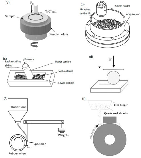
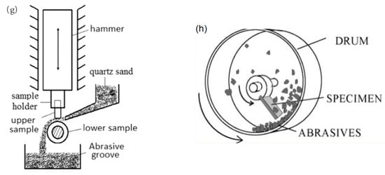
Figure 1.
Schematic diagram of several wear testing methods (a) Ball-on-disk. Adapted from [5] with permission from Elsevier, 2023; (b) Pin-on-disk. Adapted from [32], with permission from Elsevier, 2023; (c) Pin-on-plate. Adapted from [33], with permission from Emerald Publishing Limited, 2023; (d) Ball-on-plate. Adapted from [34], with permission from Elsevier, 2023; (e,f) Block-on-ring. Adapted from [9,35], with permission from AMERICAN SOCIETY OF MECHANICAL ENGINEERS and Taylor & Francis, 2023; (g) Hammered abrasion impact wear; (h) Rotary drum abrasion impact wear. Adapted from [6,8], with permission from Elsevier, 2023.
In addition to the wear testing methods, wear characterisation methods have also been divided into several categories. Generally, the wear volume or weight [2,4,5] and wear rate [3,9,38] are used for quantifying the wear of materials. Measurement of wear volume or weight is the most intuitive and concise method, and wear can be directly derived from a comparison of volumes or weights under different testing conditions [32,33,39]. The wear rate can be calculated by the following equation [3,6,8]:
where is the wear rate; is the wear weight; represents the total impact multiplied; means the material density. Wear rate can be also calculated using another equation [8]:
where W represents the wear rate; represents the scratch hardness and is the fracture strain. Equation (2) expresses the correlation between hardness together with toughness and wear performance. The mechanism of wear performance of MMSs is elaborated in depth in next chapter.
3. Wear Testing Results
Following the above-mentioned wear testing methods, a considerable number of researchers have obtained significant results to interpret the wear performance and associated wear mechanisms of different types of MMSs. For instance, Yan et al. [5] conducted ball-on-disc dry sliding tests to investigate the wear resistance and corresponding failure mechanisms of 5 Mn steels that were hot rolled and annealed at 630, 645, 660, 675 and 695 °C. It was found that the steels annealed at 675 °C exhibited the best combination of wear resistance and mechanical properties. This was due to the gradient of strain hardening contributed by the retained austenite. The ball-on-disc dry sliding tests were also used by Han et al. [40] to examine the wear behaviour of medium manganese martensitic steels (MMMSs) at different finish rolling temperatures (FRTs). The results indicated that the mass loss rate of the MMMSs was decreased by ~6% at a relatively low FRT of 700 °C and the main wear mechanism was originated from dislocation and refinement strengthening. To meet the high performance requirement under harsh mining conditions, medium manganese austenitic steels (MMASs) have been extensively applied to substitute for other MMSs, and their wear behaviour has attracted substantial interest in recent years. For example, Ge et al. [6] used an MLD-10 impact wear test equipment to investigate the impact abrasive wear properties of a MMAS, in which the quartz sand particles served as the abrasive media. The results suggested that the wear mass loss of the MMAS decreased approx. 30% compared to that of benchmark steel (martensitic wear-resistant steel, i.e., MWRS). The strengthening mechanism for the enhancement of the impact wear resistance was dominated by martensitic transformation, dislocation and stacking fault at relatively low impact energy, while the strengthening mechanism was controlled by the martensitic transformation, deformation twins and dislocation at relatively high impact energy. To explore the effects of impact energy on the wear resistance of the MMAS, Chen et al. [2] employed the same wear tester at varying impact energies from 0.5 to 6.0 J. The results showed that the best and worst wear resistance was obtained at 3.5 and 1.5 J, respectively. The wear mechanism was ascribed to the changes in the amount of martensite and the shapes of dislocation and twins under varying impact energies. Wang et al. [3] performed impact and rolling abrasive wear tests using quartz sand particles between two steel rings to reveal the wear behaviour and hardening mechanism of hot rolled MMAS (Mn8) in comparison to those of traditional Hadfield steel (Mn13). They found that the impact and rolling wear rate of Mn8 was 20% lower than that of Mn13, owing to Mn8’s better work hardening sensitivity. The wear-resistant strengthening mechanism included deformation-induced martensitic transformation, dislocation strengthening and twin strengthening. To further expand the application field of MMASs, corrosion/erosion wear behaviour of MMASs was also studied. Wang et al. [41] carried out the erosion-wear tests on a rotary erosion-wear testing machine using a hot-rolled MMAS and a commercial MMMS in various slurry environments. They concluded that the erosion-wear resistance of the MMAS outperformed that of MMMS at different erosion angles and velocities by reducing the wear rate up to 30%. The wear strengthening mechanism was determined by combined strengthening such as martensitic transformation, twin and dislocation strengthening. They also concluded that the main wear mechanism changed from the micro-cutting wear to the erosion peeling wear and local gouging abrasion with the change of erosion angle from low to high. In addition to this, Tan et al. [42] implemented sliding and impact tribocorrosion tests on an MLD-10 impact wear test equipment to evaluate the tribocorrosion performance of an MMAS and an MWRS in simulated acidic mine water. The results showed that the weight loss and wear rate of MMAS were over 20% lower than those of MMRS in both sliding and impact tribocorrosion. The enhanced tribocorrosion performance of the MMAS was caused by the strain-induced martensite transformation, good ability to form passive films and uniform corrosion. Some other researchers focused on the effect of alloy elements on the wear performance of MMSs. To name a few, Yan et al. [43] conducted ball-on-disc dry sliding tests to compare the wear performance of V-containing and V-free MMSs with that of benchmark steels, i.e., conventional wear-resistant MMMS (Hardox400 steel) and MMAS (Hadfield steel). The results indicated that the V-containing MMS presented around 3 times higher abrasive wear resistance than the benchmark steels. This was because of the microstructural refinement and improved strain hardening during wear enabled by V element. Cai et al. [44,45] also conducted ball-on-disc dry sliding tests to investigate the effect of Ti element on the wear behaviour of MMSs which were solution treated at 1000 °C and then aged at 500, 550 and 600 °C. The findings demonstrated that the Ti-containing MMAS aged at 500 °C presented the best wear resistance despite its relatively low initial hardness. The reason was related to the significant work hardening generated by the presence of ε-martensitic transformation and mechanical twins under wear deformation. A summary of the wear testing results using different MMSs compared with other wear resistant steels is outlined in Table 1. It can be seen that MMASs were more widely used as wear resistant steels compared to other MMSs, especially in the mining industry. The main mechanisms for enhanced wear resistance were thus dominated by martensitic transformation and twin strengthening which were highly related to the well-known TRIP and TWIP effects. The alloy elements such as V and Ti also played a crucial role in enhancing the wear resistance of MMSs in terms of microstructural refinement and precipitation strengthening. In addition, the processing methods such as rolling and heat treatment were of paramount importance in determining the phase constitution and microstructure of MMSs, and hence, their wear resistance. The factors that could affect the wear behaviour and performance of MMSs will be discussed in detail in Section 5.

Table 1.
A summary of the wear testing results using MMSs compared with other wear resistant steels.
4. Wear Mechanism
In general, there exist several types of wear associated with the use of mining equipment, including abrasive wear, impact wear, adhesive wear, fatigue wear and corrosive wear [2,6,37]. Among these, abrasive wear, adhesive wear and fatigue wear are generic and can transpire in all test systems. On the other hand, corrosive wear occurs in test systems with corrosive environments. Impact wear emerges in both hammer abrasion and rotary drum abrasion tests.
Abrasive wear is caused by the mechanical action of hard particles or objects rubbing against a surface and removing material [8,46]. The interaction between the abrasives and the abraded surfaces can be characterised by various mechanisms, such as microploughing, microcutting, microfatigue and microcracking [8], or cutting, wedging and ploughing [47]. Microploughing happens when the abrasive particles create grooves on the surface by ploughing it. Microcutting is the mechanism when the abrasive particles slice off the material from the surface. Repeated impact of the abrasive particles leading to crack initiation and propagation is known as microfatigue. Lastly, microcracking occurs when tensile stresses on the surface exceed its strength, leading to crack formation [8]. Cutting results in material loss, while ploughing and wedging cause plastic deformation and fatigue spalling [9].
Impact wear is a type of wear that occurs when surfaces are repeatedly subjected to high-velocity collisions with particles or objects. This enables the material to undergo plastic deformation, crack initiation and other forms of damage, leading to material loss and changes in surface properties [3,6,39]. Impact wear can cause significant problem in industrial applications, such as mining, where heavy machinery is used to break up rock and ore [37,48,49].
The wear behaviour of MMSs after abrasive and impact wear first undergoes plastic deformation, followed by the simultaneous formation of a gouge created by the abrasives pressed into the MMSs. Plough and cut damage occur due to external friction, with subsequent cracks formed near the previous gouge, leading to fatigue spalling [3,6]. The severity of abrasive and impact wear is affected by several factors, including the hardness, toughness of MMSs. The effect of surface hardness on the wear mechanism has been observed by Yan et al. [4]. It is found that the martensitic MMSs primarily subject to cutting wear, while the austenitic MMSs experience ploughing wear. In martensitic MMSs, high dislocation density in martensite, which makes it difficult for the abrasive to embed on the interface, resulting in a cutting mode of wear. As shown in Figure 2a, wear debris from the surface layer is spalled off and extruded onto the MMSs surface, and delamination has also been observed [4]. Debris generated during abrasive wear can cause additional wear by acting as additional abrasives. Hardness and toughness of the surface layer can affect the extent of cutting during abrasion. Hardness can be enhanced by the presence of abrasives [6]. In the austenite-rich MMSs (see Figure 2b), the dominant ploughing mode of wear results in a reduction of surface hardness due to the slight softness of austenite compared to martensite [2,9]. Due to the increased hardness of the sub-wear layer and the toughness of the MMSs, it is difficult to embed spalled flakes into the material surface, preventing extensive spalling, but pit and delamination still exist [5]. However, grooves can still be formed on the surface, and debris can accumulate in the grooves, leading to abrasive wear and further ploughing. Toughness in austenitic MMSs is higher than that in martensitic MMSs, due to the presence of metastable austenite in austenitic MMSs. The increased toughness enables austenitic MMSs to absorb more impact energy during impact, effectively preventing the generation and expansion of cracks in the wear layer and thus demonstrating better impact wear resistance [6].
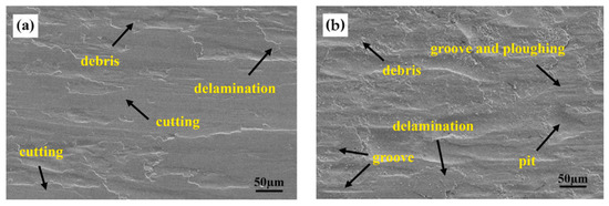
Figure 2.
Abrasive wear and impact wear behaviour in (a) martensitic MMS; (b) austenitic MMS. Adapted from [4], with permission from Elsevier, 2023.
Adhesive wear happens when two surfaces slide or rub against each other under pressure, causing them to stick together and then tear apart. It occurs when the surfaces are in close contact and the frictional force is high enough to cause deformation of the surface layers, which results in the creation of tiny welds between the surfaces. As the surfaces continue to move against each other, these welds break apart, resulting in the transfer of material from one surface to the other [4,37].
Fatigue wear is a type of wear generated due to the repeated application of cyclic loads on a material, causing microscopic cracks to initiate and propagate until the material ultimately fails. Over time, the repeated application of cyclic loads leads to the growth of cracks, which eventually coalesce and cause the material to fail [5,37].
Due to low austenite content and mostly stable film shape, the low surface hardness of the MMSs makes the TRIP effect unlikely occur, with grooves and pits forming under repeated shear stress (see Figure 3). These grooves can act as stress concentrators, leading to microcracks forming and spreading to flake peeling. As a result, a portion of the peeled abrasive material may be embedded in the MMSs surface, resulting in three-body wear, while the rest may adhere to the surface, leading to adhesive and fatigue wear [4,5].

Figure 3.
Surface morphology of MMS after adhesive and fatigue wear. Adapted from [5], with permission from Elsevier, 2023.
Corrosive wear is a type of wear that occurs when a material is subjected to both mechanical wear and corrosion simultaneously in a corrosive environment. Corrosive wear can occur due to the presence of aggressive chemicals, moisture, high temperature or pressure and other corrosive factors that can degrade the material surface while undergoing mechanical wear. Corrosive wear causes material degradation in many industries, including mining, oil and gas production and many others [50,51]. Nevertheless, corrosive wear is rarely mentioned in the study of MMSs and can therefore be investigated extensively in the future.
5. Phase Constitution and Microstructure
Phase composition and microstructure of MMSs are crucial factors affecting wear performance. The TRIP and TWIP effects, as well as heat treatment, can change the phase composition. This chapter provides insight into the effects of TRIP and TWIP on the phase transformation, as well as the influences of element and heat treatment on the distributions of phases within MMSs. By analysing these factors, this chapter aims to better understand the influence of the material’s phase transformation and elemental composition on the wear resistance of MMSs.
5.1. TRIP and TWIP Effect
The TRIP effect is a phenomenon in which the transformation of metastable austenite to martensite is induced at low stresses [3,7]. This effect enhances the toughness and hardness of MMSs by promoting plastic deformation and hindering microcrack formation [4,14]. The increase in dislocations leads to a high density of entanglement and stacking dislocations, which in turn improves the wear resistance of the MMSs. The interaction of stacking dislocations with solute atoms and Shockley dislocations can effectively inhibit slip (see Figure 4a). Furthermore, martensitic deformation leads to volume expansion and the formation of fine grains within the martensite, which results in grain refinement and further improves the wear resistance of MMSs [11,52,53]. Typically, conventional TRIP steels contain ferrite, bainite, retained austenite, and a small amount of martensite [54,55]. Etching with Nital can dissolve the ferrite and reveal an easily recognisable phase composition [56].
Figure 4.
TRIP and TWIP effects: (a) defects in phase; (b) deformed twins. Adapted from [6], with permission from Elsevier, 2023.
In addition to this, wear performance is also affected by TWIP effect of MMSs. TWIP occurs at high external energies and becomes the main strengthening mechanism at high impact energies [6]. Impact wear resistance tests have revealed deformed twins with a parallel band structure in the austenite phase of MMSs (see Figure 4b), and the twin density increases with the impact energy. The increase in dislocation density enables increased hardness, and thus, affects the wear performance of MMSs [2,6]. Twin grain formation occurs in two distinct forms, as illustrated in Figure 5. Self-partial multiplication is formed through a low stress–strain rate due to a Shockley dislocation reaction located within a stacking fault (see the left side of Figure 5). On the other hand, a rebound mechanism twin is formed at high strain rates and stresses (see the right side of Figure 5). Twins formed at high stress–strain rates tend to exhibit higher density and dislocations [2,3].
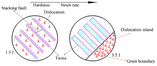
Figure 5.
Self-forming and impact-forming twins. Adapted from [2], with permission from Friction, 2023.
The occurrence of TRIP and TWIP effects is significantly influenced by the stacking fault energy (SFE) of austenite. The TWIP response becomes the dominant phenomenon when the SFE is between 20 and 50 mJ/m2, while the SFE less than 15 mJ/m2 leads to the TRIP effect. An SFE between 15 and 20 mJ/m2, however, causes the simultaneous occurrence of both TWIP and TRIP effects [13,24,57]. Researchers have found that the concurrent occurrence of TWIP and TRIP effects can significantly enhance the hardness and toughness of TWIP + TRIP MMSs [12,24]. Figure 6 illustrates the reaction mechanism of TWIP + TRIP in MMSs, which suggests that the diffusion of elements between the austenite and ferrite during IA allows twins to form within austenite, activating the TWIP effect. When twins are numerous, martensite forms at twin intersections, initiating the TRIP effect [24]. Tests conducted by Lee et al. [58] indicate that the TRIP effect occurs in larger austenite grains, while the TWIP effect occurs in finer grains. The formation of fine twins within the martensite matrix can cut through the austenite grains and refine the grain size, as shown in Figure 7 [3]. Simultaneous TWIP and TRIP effects can contribute to improved wear performance to the greatest extent [6,13]. The transformation of phases in the effect and the factors causing the transformation are discussed in the subsequent sections.
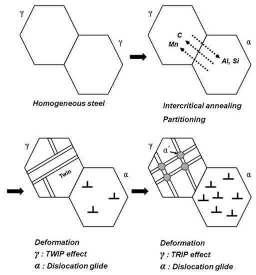
Figure 6.
Mechanism of TWIP+TRIP in MMSs. Adapted from [24], with permission from Springer Nature, 2023.
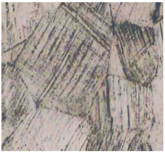
Figure 7.
Twin grain formation in martensite. Adapted from [6], with permission from Elsevier, 2023.
5.1.1. Austenite
When evaluating the wear performance of MMSs, it is essential to consider both the volume fraction and stability of the austenite, which are primarily influenced by element composition, morphologies and grain size of austenite [4,16,18]. The volume fraction and stability of metastable austenite are critical factors that affect the TRIP and TWIP effects in MMSs [4].
The reverted austenite, which remains at room temperature after heat treatment, can significantly affect the mechanical properties and wear resistance of MMSs [4,56,59]. The fraction of reverted austenite is also critical for activating the TRIP properties, and an optimal range between 20% and 40% is required for effective activation [23,25]. Retained austenite which pre-exists in MMSs before heat treatment can affect the fraction of reverted austenite. In this regard, a small amount of retained austenite is conducive to austenite reversion during annealing [59]. Additionally, some of the interlath-retained austenite prior to high temperature annealing facilitates the formation of lath austenite, which can complete the austenite-to-martensite transformation more efficiently [60]. Increasing the content of retained austenite will promote the growth of austenite around the martensite, as the hard martensite will exert an external force on the austenite, promoting its transfer to martensite earlier [61], whereas excess retained austenite inhibits the growth of reverted austenite [59]. Jha et al. [62] derived an equation to calculate the fraction of reverted austenite from their tests.
where indicates austenite diffraction peak; refers to martensite diffraction peak; is austenite volume fraction. This formula is commonly employed after observing the phase composition using X-ray diffraction (XRD) [22,63,64]. The austenite fraction can also be directly measured using electron backscatter diffraction (EBSD), but the values obtained using this method are typically lower than those obtained by XRD [65]. Nevertheless, XRD is more accurate in quantifying the austenite fraction in steels than EBSD as a wider range of surface area is scanned.
In addition to its fraction, the stability of austenite, another key point in MMSs, has gained attention and is known to be influenced by the morphology, surrounding microstructure, grain size, and elemental composition of austenite [66].
Among these factors, the morphology of austenite plays a significant role in determining the wear performance of MMSs [16]. Thin laths and carbon-rich reverted austenite improve impact toughness by impeding the crack formation. Concurrently, this morphology of austenite alleviates stress, therefore, refines the microstructure [67,68]. On the other hand, block austenite is more favourable for the TRIP effect, which can be transformed to martensite with minimal force [67,69].
Meanwhile, the surrounding microstructure affects the carbon content and external pressures exerted on austenite, leading to different austenite sizes and morphologies [70]. When austenite is dispersed in the ferrite matrix, its transformation rate is disturbed by the forces between the surrounding phase and itself [17]. The presence of martensite surrounding the austenite can affect its nucleation [20]. There are three energies that affect the austenite nucleation around martensite, namely: (a) the free energy dominated by the elemental composition and atomic structure in martensite and regression austenite, (b) the interfacial energy caused by the adjacent interfaces of different martensitic austenite and (c) the elastic energy generated by the austenite to martensite transition [71].
Moreover, a fine austenite grain size can hinder the diffusion of dislocations, which can increase the wear resistance by facilitating dislocation pile-up and tangle within the grain [20]. However, smaller grain sizes may result in fewer internal martensite nuclei and greater boundary obstruction, making it more difficult for austenite-to-martensite transformation [70,72]. Some researchers believe that the finer the grain size of austenite, the more stable austenite will be obtained when the austenite size is less than 20 μm. When the grain size is greater than 1 μm, the stability of austenite diminishes. Extremely small grain sizes, such as 0.01 μm, can prevent the transformation of austenite to martensite [73,74].
In addition to grain size, the elemental compositions in austenite, specifically carbon and Mn contents, are also considered important by some researchers [14,56,75]. Haidemenopoulos et al. [72] developed a model that represents the relationship between the austenite deformation force and elemental content. This model is given by Equation (4):
where and represent the mole contents of carbon and Mn; is the Kelvin temperature of the material. Arnzabal et al. [76] also noted that decreasing the carbon content resulted in lowered mechanical energy required for austenite transformation. Jimenez-Melero et al. [74] found that low carbon content and large grain size reduced the stability of austenite, leading to its transformation to martensite at higher temperatures. The distribution of Mn in MMSs affects the stability of austenite, as demonstrated by observing the hardness [66]. Nakada et al. [19] attributed the stability of austenite transformed from martensite at room temperature to the concentrations of carbon and Mn.
It can be observed from research that the stability of austenite is affected by various factors, and some studies have focused on the combined influence of multiple factors. Lee et al. [77] found that the austenite can only be stabilised at room temperature when the grain size was less than 500 nm and combined with the diffusion of Mn, suggesting that dislocations did not make austenite stable. Melero et al. [73,76] derived that only small grains of austenite with high carbon content can exist at room temperature. Melero et al. [73] suggested that the high carbon content was critical for the stability of large grain austenite, while for austenite size less than 15 μm, grain size becomes a more important influencing factor. Li et al. [63] found that short-grained lath austenite is more stable than long-grained austenite due to the higher carbon content in short-grained austenite and more uniform distribution of Mn.
The stability of austenite can be expressed by the value of , where lower values of indicate more stable austenite. This value is found to be minimum between 100 and 200 °C and increases with temperature beyond this range [78,79]. Cai et al. [66] also supported this perspective and suggested that the grain size of austenite increases with temperature, leading to reduced stability. They concluded that austenite grain size is a decisive factor in determining the stability of austenite, with an optimal stability observed at around 0.6 μm. The value formula is widely used to calculate austenite stability in various studies [80,81,82].
where , and represent the mechanical stability coefficient of retained austenite, austenite fraction before deformation and austenite fraction after strained to , respectively.
It can be concluded that the wear performance of austenite-rich MMSs depend on increased dislocations, martensitic transformation and grain refinement [4,5]. As mentioned before, both hardness and toughness are important in improving the wear resistance of MMSs. To minimise the effects of abrasive wear, materials with high hardness and toughness are typically used in abrasive environments. High hardness reduces grooving, while high toughness retards crack formation and material loss. However, in hardness–wear correlation tests, it was noted that there was no linear relationship between the hardness and wear performance of MMSs, as illustrated in Figure 8. Hardness is thus a subordinate condition affecting wear performance [8,9,10]. Ojala et al. [32] suggested that the toughness of MMSs is important to its wear performance. This has also been confirmed by Ge et al. [6], whose tests showed that MMSs with low hardness and high toughness exhibit better wear resistance, as high toughness prevents the crack formation, and thus, reduces fatigue spalling of the MMSs, while toughness is associated with metastable austenite. The different wear performance of the same hardness in MMSs are due to the different internal phase compositions [5,8,9]. Thus, the internal phase of MMSs must also be considered.
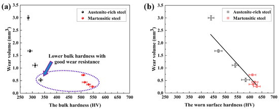
Figure 8.
Relationship between the hardness and wear volume: (a) Bulk hardness; (b) Surface hardness. Adapted from [4], with permission from Elsevier, 2023.
The wear performance needs to be determined by the phase of the hardened layer [8]. Metastable austenitic and ferritic structural MMSs are significantly deformed due to wear, resulting in thickening of the hardened layer. In the impacted abrasive process, the austenite in the wear layer transforms to martensite to form a work-hardened layer and a new one will form as the original one abraded. The hardness of the hardened layer decreases in a gradient with depth [3,6]. However, this does not occur in martensitic MMSs [4,5]. In austenite-rich MMSs, the austenite content and morphology cause varying degrees of TRIP effect, with higher austenite content increasing the thickness and hardness of the hardened layer. The formation of the hardened layer is continuous, and the constant sub-surface hardening layer provides stress support [5]. Subsequent sliding wear causes dislocation accumulation, leading to grain refinement beneath the hardened layer, which increases hardness, reduces stress concentration and delays crack formation [4].
5.1.2. Martensite
Compared to austenitic steels, martensitic steels are better in terms of wear resistance due to their high hardness. In martensitic MMSs, the thickness of the hardened layer is thin, although the plastic deformation caused by wear produces a high number of dislocations that enhance hardness [5]. The role of the hardened layer is very important for the study of MMSs’ wear performance [4]. Figure 9 shows the relationship between the surface hardness and distance for martensitic and austenitic MMSs, with a direct reduction in surface hardness at a certain point for martensitic MMSs and a trend of slow decrease for austenitic MMSs.
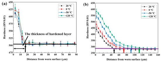
Figure 9.
Relationship between the surface hardness and distance in (a) martensitic MMSs; (b) austenitic MMSs. Adapted from [4], with permission from Elsevier, 2023.
As described in the previous section, austenite stability directly affects the TRIP effect. The stability of austenite can be deduced from its grain size, elemental composition, etc. The martensite start temperature is simultaneously influenced by the above factors in austenite, so it can also be used to calculate the stability of austenite [74,83,84].
Austenitic grain refinement, which causes a reduction in packet size and block length, increased high-angle dislocations and decreased martensite start and finish temperatures [75,85]. The model proposed by Lee et al. [18] also suggested that considering austenite grain size would reduce the martensite start temperature. The equation proposed by Yang and Bhadeshia [86] can be used to relate the austenite grain size and martensite starting temperature. The equation is given by:
where represents the martensite start temperature at an infinite austenite grain size; a and b are empirical fitting constants; represents the average volume of austenite; is the martensite fraction and m is the martensite grain length to width ratio.
Wang et al. [75] utilised Equation (7) to validate the relationship between the carbon content and martensite start temperature.
where the variable represents the carbon content in austenite. Apart from this, a model that correlates the content of various elements to the martensite start temperature has also been proposed [24,77,87].
where , , , represent the total contents of carbon, Mn, Al, and Si, respectively. The formula have also been modified to incorporate the correlation between the austenite grain volume and martensite start temperature [18].
where refers to the average austenite grain volume. The relationship between the martensite content and its start temperature has also been investigated [18,88]:
where represents the martensite content; and are the kinetic correlation constants; is the martensite start temperature and , represent the total carbon and Mn contents, respectively.
5.1.3. Ferrite
In some MMSs, ferrite can coexist with retained austenite. In TRIP MMSs, annealing with a Kurdjumov–Sachs orientation relationship results in the formation of ferrite and retained austenite [25,89]. The effects of the phase transformation of ferrite on wear performance have been studied by several research teams. It has been observed that film-like austenite grows at the ferrite boundary in rich austenite steel [4]. Intercritical ferrite can split austenite into different sizes, which provides a range of degrees of stability and a variety of TRIP reactions at different stages [64,90]. The continuous TRIP effect contributes to the sustained wear resistance of MMSs.
In addition, elemental diffusion also influences the wear performance of MMSs. An increased carbon concentration in ferrite reduces the toughness of MMSs [69]. During heat treatment, however, Mn in ferrite is transferred to austenite, and under the influence of the Mn concentration, carbon also diffuses, enhancing the stability of austenite [91], which in turn increases the toughness of MMSs and improves the impact wear performance.
5.2. Effects of Alloy Elements
In conjunction with hardness, toughness and the structure of hardened layers, the elemental composition of MMSs also affects the wear resistance of materials [32,39]. Figure 10 illustrates the correlation between the carbon content and wear resistance, where A–C and F denote non-martensitic steels, while D and E represent martensitic steels. The wear loss decreases with increasing carbon content [39]. Alloying elements and their amounts greatly affect the wear resistance of MMSs. In order to ensure desirable wear performance, sufficient amounts of carbon, B, Ni, and Mo are required in MMSs [32]. In this section, several crucial elements in MMSs will be discussed.
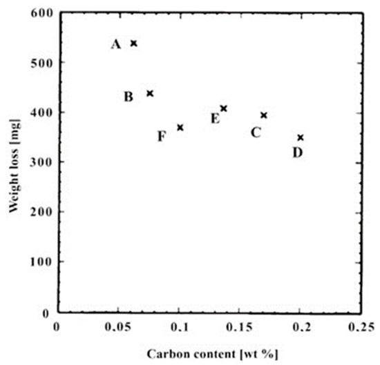
Figure 10.
Relationship between carbon content and weight loss (A–C and F denote non-martensitic steels, while D and E represent martensitic steels). Adapted from [39], with permission from Elsevier, 2023.
Carbon is particularly important for enhancing the hardness of MMSs [32]. A prolonged heat treatment duration promotes a more uniform distribution of carbon content within the austenite phase [69,73]. By stabilising the austenite, the toughness of MMSs can also be improved [61,92]. Additionally, increased carbon and Mn contents can elevate the SFE of austenite, leading to the production of the TWIP effect and decreased martensite start temperature [24].
Mn exerts a stronger influence on MMSs compared to carbon. Experiments by Moor et al. [83] indicated that the presence of carbon played a minimal role in austenite retained at room temperature, but the addition of Mn significantly enhanced the austenite content. In the presence of Mn, it diffuses into the newly formed austenite, stabilising it and preventing its transformation to martensite during quenching. Contrarily, the retained austenite becomes unstable and transforms to martensite during quenching [59]. To address this issue, Zou and Tsuchiyama et al. [14,91] have used partitioning after IA to stabilise the Mn element and found that both isolated austenite dispersed in tempered martensite and lath austenite surrounded by quenched martensite were stabilised by Mn at room temperature. Additionally, the enhanced Mn content increases the hardness of MMSs [93].
The addition of Cr and Mo to MMSs has various positive effects on wear performance. Cr can enhance wear and corrosion resistance, formability, toughness, strength, ductility and weldability [94]. Similarly, Mo improves the hardenability of MMSs and can improve wear resistance, especially when combined with Ni [32] and also refines the grain structure of MMSs. The inclusion of Ti elements in MMSs containing Cr can significantly improve wear resistance and replace the need for expensive Mo [6,95]. Additionally, the addition of Cr and Mo can compensate for any reduction in Mn content and increase thermal conductivity by modifying the structure of carbon and Mn. Thus, the addition of these elements can improve the durability of MMSs, making it more suitable for various applications, such as mining [6,7].
Al and Si are commonly added to promote the TRIP effect of MMSs [96,97]. However, it is essential to note that increasing the Al content and decreasing Si content result in the formation of more white brittle martensite. White brittle martensite is highly brittle and not conducive to improving wear resistance of MMSs [32]. SUH et al. [98] have suggested that the addition of more than 3% Al inhibits the formation of austenite at high temperatures during heat treatment. As shown in Figure 11, the yellow phases represent bcc and the red phases represent fcc (Misorientation is between 2 and 15° for purple line and more than 15° for green line) [99]. This inhibition leads to the formation of a ferrite-martensite dual phase that regulates the austenite fraction, which is detrimental to the enhancement of the toughness of MMSs. The addition of Si to MMSs has both positive and negative effects on properties. On one hand, Si can elevate the ferrite phase and inhibit the precipitation of carbide from austenite. This prevention allows for higher dispersion of carbon into austenite and enhances its stability [5,17,20]. On the other hand, Si can promote planar slip and dislocations, leading to the transformation of reverted austenite to martensite [5]. Additionally, increased Si content helps improve tensile strength, but reduce yield stress [61]. Meanwhile, Si and Cr tend to reduce the SFE of austenite, while Al has the opposite effect [24,100].
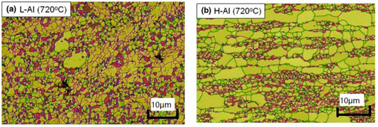
Figure 11.
(a) Low-Al alloy annealed at 720 °C; (b) High-Al alloy annealed at 720 °C. Adapted from [98], with permission from Springer Nature, 2023.
Furthermore, Nb helps refine austenite grains, reduce the martensite start temperature, retard recrystallisation of austenite and accelerate the transformation of bainite. These improvements result in more carbon being enriched into the austenite and increasing its stability [65]. The addition of V can also provide several benefits: it refines grain size, inhibits carbide formation and improves wear performance. Moreover, V carbides can increase the yield stress of MMSs [6,101]. The inclusion of N can enhance the corrosion resistance of MMSs [102]. On the other hand, B significantly promotes the transformation of martensite, and therefore, improves the wear resistance of materials [32]. Rare earth metals are also useful elements in MMSs. They can inhibit carbide formation, improve thermal conductivity and promote martensite phase transformation by reducing the SFE [7]. Overall, the addition of these elements can improve the wear performance of MMSs, making it more suitable for various applications, such as the scraper conveyor used in mining industry.
5.3. Effect of Heat Treatment
Apart from the elemental composition, heat treatment processes also perform an essential role in investigating the wear performance of MMSs. Phase and elemental distribution within MMSs are changed by heat treatment. Mechanical properties, such as hardness and toughness can be improved, which subsequently affect the wear resistance of MMSs. The SFE of austenite is also determined by the heating temperature, with SFE decreasing at lower temperatures [99]. Figure 12 depicts the interdependence of hardness and phase fraction after different heat treatments, highlighting the effect of heat treatment on wear performance. In this section, several common heat treatment processes are explored to analyse their effects on the phase constitution, microstructure and wear performance of MMSs.
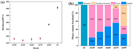
Figure 12.
Hardness and phase fraction vary with temperature (a) The hardness after different heat treatments; (b) The phase fraction after different heat treatments. Adapted from [5], with permission from Elsevier, 2023.
5.3.1. IA
MMSs are commonly treated with IA, with the annealing temperature ranging between the austenite transformation temperature Ac1 and complete austenisation temperature Ac3/Acm. An abundance of austenite can be achieved when the temperature is slightly lower than Ac3/Acm [83]. The temperature, time, heating and cooling rates used during the IA process can influence the fraction, SFE, morphology, size and element composition of austenite [15,22,23]. The changes in the phase constitution, in turn, affect the MMSs’ wear performance.
Temperature affects the content and SFE of austenite (Figure 13). Some researchers believe that the austenite fraction rises with temperature due to the elevated carbon and Mn contents in the austenite. This is because carbon and Mn diffuse from ferrite to austenite during annealing, as shown in Figure 14 [63,76]. However, another perspective is that the fraction of austenite first increases with increasing temperature and then decreases [82]. Lee’s research group [13,18] introduced the concept of Tm, which is the IA temperature that yields the highest fraction of austenite at room temperature, as illustrated in Figure 13. They discovered that annealing at temperatures slightly below Tm results in the best mechanical properties. When annealed at this temperature, a mixture of austenite and ferrite phases forms, which prevents the formation of thermal martensite with an austenite SFE of approximately 20 mJ/m2. The TWIP and TRIP effects are thereby promoted [13,18,103].
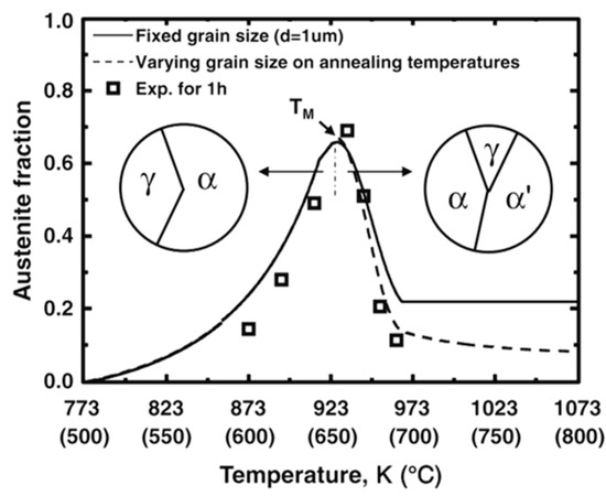
Figure 13.
The Tm temperature is marked out. When the tempering temperature is below Tm, the ferrite and austenite phases are present, when the temperature is above Tm, the martensitic phase appears. Adapted from [18], with permission from Springer Nature, 2023.
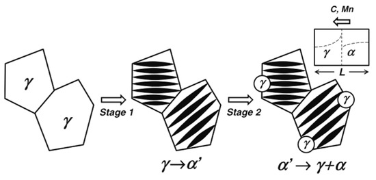
Figure 14.
Stage I shows the transformation of austenite to martensite during TRIP. Stage II indicates the transformation of martensite to austenite and ferrite during heat treatment and shows the direction of diffusion of carbon and Mn elements. Adapted from [18], with permission from Springer Nature, 2023.
In addition, temperature also affects the phase morphology and size in MMSs. At high temperatures, austenite is more likely to transform into martensite during quenching due to the formation of block austenite, whereas low temperatures result in lath austenite [67,82]. After annealing, reverted austenite and ferrite are the main phases in MMSs, and their particle sizes increase with temperature and time [18,25,104], as listed in Table 2. Additionally, altering the IA temperature also affects the morphology of martensite and cementite [105]. During the heat treatment process, carbon gradually transports into austenite due to the reduction of dislocations in the martensite. With time, the martensite transforms from tempered martensite to globular martensite, resulting in a gradual decrease in hardness [21,91,106]. Tempered martensite contains a high carbon content, and its transformation is due to recrystallisation during deformation [26,76]. Martensite content increases with temperature, which in turn affects the austenite morphology [16,89].
Table 2.
Average grain size of austenite and ferrite after IA (in μm). Adapted from [104], with permission from Springer Nature, 2023.
Cai et al. [66] found that increasing the annealing time results in a more even distribution of Mn, leading to increased stability of austenite. Li et al. [18,77,107] also agreed that longer annealing times lead to more uniform distributions of carbon and Mn (See Figure 15), enhancing the stability of austenite and resulting in lower TRIP with fewer dislocations. During testing, Yang et al. [22] found that the austenite fraction will not be affected by the temperature when the annealing time was short, but when the annealing time was extended to 5 h, the austenite fraction decreased with increasing temperature. Yan’s research team [20] also confirmed this view. For extremely fine austenite grains, the diffusion of Mn is also rapid at low temperatures for a short period of time [108].
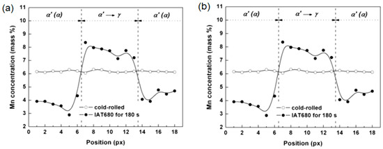
Figure 15.
Mn concentration in austenite during IA (a) 180 s; (b) 24 h. Adapted from [77], with permission from Elsevier, 2023.
The production of phases in MMSs is also influenced by the heating and cooling rates. When the heating rate is lower than 15 °C·s−1, a diffusion transition from martensite to austenite occurs. Mn diffuses in the austenite and form fine grained austenite with high Mn content. Austenite will also form around the pre-formed cementite, causing an increase in start and finish temperatures and the cementite precipitation start temperature. These phenomena disappear when the rate is higher than 15 °C·s−1, and cementite will not participate in the austenite transformation (see Figure 16) [23]. In addition, a slower cooling rate leads to higher concentrations of carbon and Mn in the austenite phase, which increases the fraction of austenite and decreases the martensite start temperature, resulting in a gradual reduction in MMSs hardness [93].
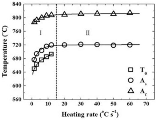
Figure 16.
Effect of heating rate on austenite start temperature, finish temperature and cementite precipitation start temperature of MMSs. Adapted from [23], with permission from Elsevier, 2023.
Phase changes in the heat treatment further affect the wear characteristics of MMSs. Austenite usually nucleates at the boundaries of martensite. Tempered martensite is a typical phase in hot-rolled MMSs [23,25]. During IA process, the formation of austenite at the boundary of martensite and ferrite is also affected by the diffusions of carbon and Mn in the reverted austenite [91,108,109]. The growth of austenite from martensite boundary is first controlled by carbon diffusion and then by Mn diffusion [19,20,21], as demonstrated in Figure 17. Meanwhile, the austenite nucleation process is highly influenced by the martensite boundary, as the angle of the boundary affects the elastic and interfacial energy during austenite nucleation. Austenite commonly nucleates at the high angle boundary of martensite before appearing at the low angle boundary, as shown in Figure 18 [89]. Han et al. [25] reported that reverted austenite forms and grows at block boundaries, which proves the previous statement. On the other hand, Cao et al. [89] suggested that ultra-fine lath austenite containing parallel dislocations would nucleate at lath martensite boundaries, while globular austenite was also found at martensite packets and pre-existing austenite boundaries.
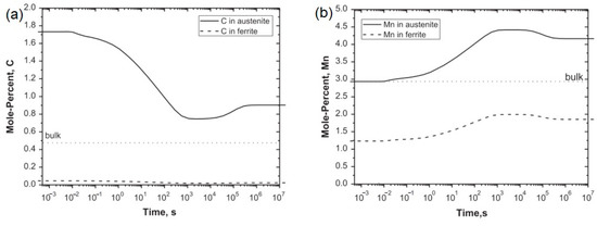
Figure 17.
(a) Carbon and (b) Mn concentration at different times during IA. Adapted from [21], with permission from Elsevier, 2023.
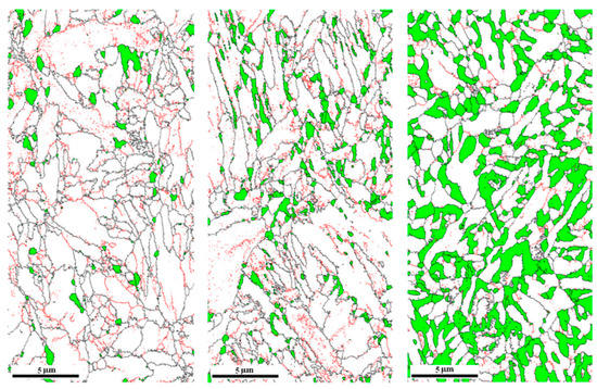
Figure 18.
Microstructure of austenite growing at the martensite boundary. The red lines refer to the low angle boundaries between 3° and 15° and the black lines present the high angle boundaries with misorientation larger than 15°. Adapted from [89], with permission from Elsevier, 2023.
Moreover, needles and rods of M3C carbides have been found to precipitate at lath martensite boundaries. Since cementite forms early in the heating process and usually precipitates at the boundary of austenite or martensite. The precipitation of cementite results in the separation of carbon and Mn. As time progresses, the temperature rises above the equilibrium temperature of cementite, leading to its dissolution. As a result, the carbon and Mn become enriched at the boundary due to the dissolution of cementite [26]. This also allows the austenite formed after its dissolution to obtain a higher content of carbon and Mn. In addition, the diffusion of these elements into the martensite also occurs accordingly [20,26].
5.3.2. Quenching plus IA
Utilising the Q + IA process [59], austenite, ferrite, and some quenched martensite are formed in MMSs that undergo Q + IA treatment, as shown in Figure 19. The microstructure of MMSs heat treated with IA and Q + IA is compared in Figure 20. The amount of martensite increases as the Q + IA temperature increases, while the content of austenite is inversely proportional to the Q + IA temperature and directly proportional to the annealing temperature. The ferrite content decreases with increasing the annealing temperature [107]. Furthermore, Tsuchiyama et al. [91] reported that when only heat treated with IA, the diffusion of Mn is slow and incomplete. They employed a technique of quenching MMSs between the martensite initiation and termination temperatures, followed by IA. Test results indicate that only the austenite formed during the heat treatment is stable due to the diffusion of carbon and Mn, and the retained austenite is highly susceptible to transformation into martensite [91].
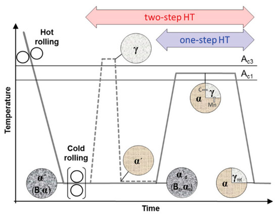
Figure 19.
Illustrations of one-step IA and two-step Q + IA routines. Adapted from [93], with permission from Taylor & Francis, 2023.
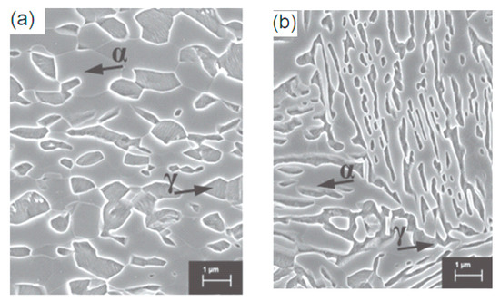
Figure 20.
(a) Microstructure after IA; (b) Microstructure after Q + IA. Adapted from [93], with permission from Taylor & Francis, 2023.
Figure 21 displays the phase transformation in Q + IA at various temperatures. At low temperatures, ferrite, lath-like austenite and cementite are present. As the temperature rises, cementite dissolves and tempered martensite is formed. If the temperature is further increased, martensite is self-tempering during cooling, and some of the cementite are visible in the martensitic crystals [93]. However, increasing the temperature may also lead to the dissolution of retained carbides, which may obstruct the TRIP effect [109].
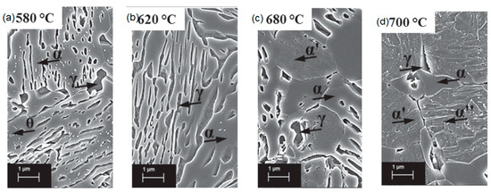
Figure 21.
Microstructure of steel for Q + IA at different temperatures (a) 580 ℃; (b) 620 ℃; (c) 680 ℃; (d) 700 ℃. Adapted from [97], with permission from Taylor & Francis, 2023.
The phenomenon observed by Han et al. [25] partially overlaps with their findings above. Firstly, when the austenitising temperature is increased, the size of block or pack martensite, austenite and ferrite increased, but the size of the laths phases is unaffected. Secondly, the austenite fraction decreases with increasing annealing temperature. Thirdly, the density of martensite boundaries decreases, which slows down the austenite nucleation. They explained this phenomenon by suggesting that the decrease in boundary density reduces the availability of nucleation sites for austenite, thereby decreasing the rate of TRIP. These observations are illustrated in Figure 22. Changes in austenite content, stability and morphology have an impact on the TRIP effect of MMSs, which affects their wear performance.
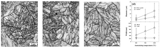
Figure 22.
Microstructure of boundaries at different Q + IA temperatures: (a) 800 °C; (b) 900 °C; (c) 1000 °C; (d) temperature effects on morphology. Adapted from [25], with permission from Taylor & Francis, 2023.
5.3.3. Quenching plus Tempering
Tempering after quenching (Q and T) is a process that helps eliminate internal stresses in MMSs and facilitates the diffusions of carbon and Mn from ferrite to austenite [16]. Xu et al. [92] concluded that during tempering, the lamellar duplex structure remained almost unchanged, but carbides began to precipitate in the ferrite slats, resulting in increased fraction and carbon content of reverted austenite. Cai et al. [64] demonstrated that Q and T can lead to a more uniform distribution of carbon in the austenite.
5.3.4. Quenching plus Partitioning
Speer et al. [110] proposed a novel approach to Quenching and Partitioning (Q and P), to obtain austenite and martensite of specific composition after complete or incomplete austenisation. It is followed by heat treatment to control the diffusion of carbon and thus provide stability. Q and P results in ultra-fine lath-like austenite, which is more stable [14]. This approach stabilises austenite using the diffusion of carbon and is different from conventional Q and T [110]. To achieve greater stability, Clarke et al. [96] performed quenching followed by partitioning at 400 °C, allowing the carbon diffusion from the martensite into the austenite. The Stewart team [111] developed a Q and P method for steel plates by cooling the inner and outer regions of the plate at different rates, resulting in different martensite start temperatures to obtain a specific fraction of stable phases.
5.3.5. Cold Rolled plus IA
Cold deformation of MMSs generates a wider variety of defects compared to hot rolling, resulting in martensite with different boundary angles and facilitating a more uniform and extensive distribution of austenite during nucleation. Additionally, cold deformation can directly reduce the plate thickness, thus making it more amenable to processing [26,71,109]. After annealing, the hot-rolled steel forms laths of martensite and austenite, whereas the cold-rolled steel forms globular martensite and austenite with high Mn content in the austenite and low Mn content in the martensite [26,109]. Wang et al. [71] found that the austenite formation process was accelerated, and the morphology was more widely distributed in the cold rolled steel compared to that in the hot rolled steel (see Figure 23). They also reported that optimum wear performance was obtained when the material was annealed for 1 h after cold rolling.
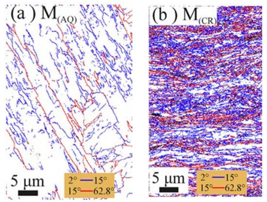
Figure 23.
Austenite morphology in (a) hot-rolled steel and (b) cold-rolled steel. Adapted from [71], with permission from Elsevier, 2023.
5.3.6. Deep Cryogenic Treatment plus IA
The feasibility of applying deep cryogenic treatment prior to IA (DCT +IA) has been studied. Yan et al. [20] suggested that DCT + IA can yield austenite with a finer grain size and uniform distribution of Mn, resulting in a better TRIP effect. This is because austenite obtained through IA is typically nucleated between the martensite laths and gradually diffuses into the ferrite, with the segregation of Mn contributing to the growth of austenite into the laths. In the case of DCT austenite, however, nucleation occurs at the boundary between the cementite and ferrite, and the presence of cementite can impede the driving force of martensite on austenite and the dissolution of cementite under austenite envelopes (see Figure 24).
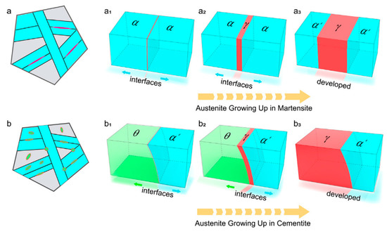
Figure 24.
Austenite growth process in two cases (a) IA (a1–a3 indicates austenite nucleation and gradual growth in martensite); (b) DCT + IA (b1–b3 indicates austenite nucleation and gradual growth in cementite). Adapted from [20], with permission from Elsevier, 2023.
6. Conclusions
This review has comprehensively analysed the wear mechanisms of MMSs, highlighting the importance of internal phase transformation and elemental composition during TRIP and TWIP, as well as heat treatment processes. The wear testing and characterisation methods were discussed to understand the influence of hardness, toughness and hardened layer on the wear mechanism of MMSs. Typical wear testing results were summarised using different types of MMSs compared with other wear resistant steels to introduce the key factors that could affect the wear performance of MMSs. Abrasive wear, adhesive wear, corrosive wear, fatigue wear and impact wear were identified as the main types of wear existing in MMSs, with microstructural analysis revealing that the internal structure of the hardened layer is the primary factor affecting the wear performance of MMSs. The TRIP and TWIP effects were discussed, along with the effects of elements and heat treatment on the phase transformation of MMSs. TRIP is mainly influenced by the metastable austenite of MMSs, which deforms to the martensitic phase when subjected to external forces. TWIP effect occurs in some MMSs, where twin deformation increases the crystal density to a certain extent, leading to increased wear resistance. Different alloying elements such as Cr, Mo, Ti, V and B also contribute to the wear resistance of MMSs. During the heat treatment process, C and Mn diffuse uniformly back into the austenite, while new film-like austenite is formed, all of which enable increased stability of austenite, augmented volume fraction of austenite at room temperature and the ease of the occurrence of TRIP. Based on the comprehensive understanding of the wear mechanisms of MMSs presented in this review, it is expected that their wear characteristics will be effectively optimised. This will promote the development of more durable and reliable MMSs for mining equipment that are resistant to harsh environmental conditions.
7. Outlook
Several directions that are worth exploring in the future are provided as follows:
- Abrasive wear, adhesive wear, fatigue wear and impact wear have been studied in MMSs, while corrosive wear—another common form of wear in mining environments—has received less attention. Future exploration of the corrosion resistance of MMSs may provide valuable insights into their suitability for applications in mining equipment;
- Although the effects of heating temperature and soaking time in heat treatment have been studied, the effect of cooling rate during heat treatment has been relatively overlooked. The cooling rate plays a critical role in determining the formation of different phases in MMSs, and further investigation into its impact on the wear performance of MMSs is thus indispensable;
- As MMSs start to popularise their application in the mining industry, abrasive media such as coal, coal gangue and quartz sand, which are highly related to the external environmental conditions, need to be incorporated in the wear testing of MMSs;
- Bimetal composites combine the excellent wear resistance of MMSs with satisfying mechanical properties of mild steels for the purpose of reducing the entire material cost but ensuring required overall performance. Therefore, they can be considered for use in mining equipment such as the scraper conveyor and mining truck.
Author Contributions
Conceptualization, S.J. and Z.J.; methodology, H.W.; validation, X.L. and Z.X.; investigation, Z.X. and H.L.; resources, X.L. and L.Z.; writing—original draft preparation, J.Y., M.Z. and H.W.; writing—review and editing, H.W. and Z.J.; visualization, Z.X. and H.L.; supervision, H.W. and Z.J.; project administration, X.L., H.L., L.Z. and S.J.; funding acquisition, Z.J. All authors have read and agreed to the published version of the manuscript.
Funding
This research was funded by Baosteel-Australia Joint Research and Development Centre under the project of BA19011 and Azure Mining Technology Pty Ltd. under the collaboration research project of AMT2023030.
Data Availability Statement
Not applicable.
Conflicts of Interest
The authors declare no conflict of interest.
Nomenclature
| wear rate | |
| wear weight | |
| material density | |
| total impact multiplied | |
| scratch hardness | |
| fracture strain | |
| austenite volume fraction | |
| austenite diffraction peak | |
| martensite diffraction peak | |
| austenite deformation force | |
| contents of carbon | |
| contents of Mn | |
| Kelvin temperature | |
| austenite fraction before deformation | |
| austenite fraction after strained | |
| mechanical stability coefficient | |
| martensite start temperature | |
| a | empirical fitting constants |
| b | empirical fitting constants |
| martensite fraction | |
| m | martensite grain length to width ratio |
| contents of Si | |
| contents of Al | |
| average austenite grain volume | |
| kinetic correlation constants | |
| kinetic correlation constants | |
| MMS | medium manganese steel |
| TRIP | transformation induced plasticity |
| TWIP | twinning induced plasticity |
| IA | intercritical annealing |
| DCT | deep cryogenic treatment |
| SFE | stacking fault energy |
| XRD | X-ray diffraction |
| EBSD | electron backscatter diffraction |
| MMMS | medium manganese martensitic steel |
| FRT | finish rolling temperature |
| MMAS | medium manganese austenitic steel |
| MWRS | martensitic wear-resistant steel |
References
- He, Z.; Qi, C.; Fu, S.; Xie, J. Improved work-hardening ability and wear resistance of austenitic manganese steel under non-severe impact-loading conditions. Wear 1987, 120, 305–319. [Google Scholar] [CrossRef]
- Chen, H.; Zhao, D.; Wang, Q.; Qiang, Y.; Qi, J. Effects of impact energy on the wear resistance and work hardening mechanism of medium manganese austenitic steel. Friction 2017, 5, 447–454. [Google Scholar] [CrossRef]
- Wang, J.; Wang, Q.; Zhang, X.; Zhang, D. Impact and Rolling Abrasive Wear Behavior and Hardening Mechanism for Hot-Rolled Medium-Manganese Steel. J. Tribol. 2018, 140. [Google Scholar] [CrossRef]
- Yan, X.; Hu, J.; Wang, L.; Chai, Z.; Sun, W.; Xu, W. The coupled effect of thermal and mechanical stabilities of austenite on the wear resistance in a 0.2C–5Mn-1.6Si steel down to cryogenic temperatures. Wear 2021, 486–487. [Google Scholar] [CrossRef]
- Yan, X.; Hu, J.; Yu, H.; Wang, C.; Xu, W. Unraveling the significant role of retained austenite on the dry sliding wear behavior of medium manganese steel. Wear 2021, 476. [Google Scholar] [CrossRef]
- Ge, S.; Wang, Q.; Wang, J. The impact wear-resistance enhancement mechanism of medium manganese steel and its applications in mining machines. Wear 2017, 376–377, 1097–1104. [Google Scholar] [CrossRef]
- Chen, S.-c.; Ye, H.-x.; Lin, X.-q. Effect of rare earth and alloying elements on the thermal conductivity of austenitic medium manganese steel. Int. J. Miner. Metall. Mater. 2017, 24, 670–674. [Google Scholar] [CrossRef]
- Rendón, J.; Olsson, M. Abrasive wear resistance of some commercial abrasion resistant steels evaluated by laboratory test methods. Wear 2009, 267, 2055–2061. [Google Scholar] [CrossRef]
- Chen, H.; Guo, H.; Shang, C.J. Study on wear behaviours of 400 and 450 grade wear resistant steels. Mater. Res. Innov. 2014, 18, S4-270-S274-275. [Google Scholar] [CrossRef]
- Jost, N.; Schmidt, I. Friction-induced martensitic transformation in austenitic manganese steels. Wear 1986, 111, 377–389. [Google Scholar] [CrossRef]
- Gibbs, P.J.; De Cooman, B.C.; Brown, D.W.; Clausen, B.; Schroth, J.G.; Merwin, M.J.; Matlock, D.K. Strain partitioning in ultra-fine grained medium-manganese transformation induced plasticity steel. Mater. Sci. Eng. A 2014, 609, 323–333. [Google Scholar] [CrossRef]
- Latypov, M.I.; Shin, S.; De Cooman, B.C.; Kim, H.S. Micromechanical finite element analysis of strain partitioning in multiphase medium manganese TWIP+TRIP steel. Acta Mater. 2016, 108, 219–228. [Google Scholar] [CrossRef]
- Lee, S.; Lee, K.; De Cooman, B.C. Observation of the TWIP + TRIP Plasticity-Enhancement Mechanism in Al-Added 6 Wt Pct Medium Mn Steel. Metall. Mater. Trans. A 2015, 46, 2356–2363. [Google Scholar] [CrossRef]
- Zou, Y.; Xu, Y.B.; Hu, Z.P.; Gu, X.L.; Peng, F.; Tan, X.D.; Chen, S.Q.; Han, D.T.; Misra, R.D.K.; Wang, G.D. Austenite stability and its effect on the toughness of a high strength ultra-low carbon medium manganese steel plate. Mater. Sci. Eng. A 2016, 675, 153–163. [Google Scholar] [CrossRef]
- Lee, S.; De Cooman, B.C. Annealing Temperature Dependence of the Tensile Behavior of 10 pct Mn Multi-phase TWIP-TRIP Steel. Metall. Mater. Trans. A 2014, 45, 6039–6052. [Google Scholar] [CrossRef]
- Cai, Z.H.; Ding, H.; Xue, X.; Xin, Q.B. Microstructural evolution and mechanical properties of hot-rolled 11% manganese TRIP steel. Mater. Sci. Eng. A 2013, 560, 388–395. [Google Scholar] [CrossRef]
- Jacques, P.J.; Delannay, F.; Ladrière, J. On the influence of interactions between phases on the mechanical stability of retained austenite in transformation-induced plasticity multiphase steels. Metall. Mater. Trading A 2001, 32A, 2759–2768. [Google Scholar] [CrossRef]
- Lee, S.; De Cooman, B.C. On the Selection of the Optimal Intercritical Annealing Temperature for Medium Mn TRIP Steel. Metall. Mater. Trans. A 2013, 44, 5018–5024. [Google Scholar] [CrossRef]
- Nakada, N.; Mizutani, K.; Tsuchiyama, T.; Takaki, S. Difference in transformation behavior between ferrite and austenite formations in medium manganese steel. Acta Mater. 2014, 65, 251–258. [Google Scholar] [CrossRef]
- Yan, N.; Di, H.; Misra, R.D.K.; Huang, H.; Li, Y. Enhancing austenite stability in a new medium-Mn steel by combining deep cryogenic treatment and intercritical annealing: An experimental and theoretical study. Mater. Sci. Eng. A 2019, 753, 11–21. [Google Scholar] [CrossRef]
- Wei, R.; Enomoto, M.; Hadian, R.; Zurob, H.S.; Purdy, G.R. Growth of austenite from as-quenched martensite during intercritical annealing in an Fe–0.1C–3Mn–1.5Si alloy. Acta Mater. 2013, 61, 697–707. [Google Scholar] [CrossRef]
- Yang, F.; Luo, H.; Hu, C.; Pu, E.; Dong, H. Effects of intercritical annealing process on microstructures and tensile properties of cold-rolled 7Mn steel. Mater. Sci. Eng. A 2017, 685, 115–122. [Google Scholar] [CrossRef]
- Han, J.; Lee, Y.-K. The effects of the heating rate on the reverse transformation mechanism and the phase stability of reverted austenite in medium Mn steels. Acta Mater. 2014, 67, 354–361. [Google Scholar] [CrossRef]
- Lee, S.; De Cooman, B.C. Tensile Behavior of Intercritically Annealed 10 pct Mn Multi-phase Steel. Metall. Mater. Trans. A 2013, 45, 709–716. [Google Scholar] [CrossRef]
- Han, J.; Lee, S.-J.; Lee, C.-Y.; Lee, S.; Jo, S.Y.; Lee, Y.-K. The size effect of initial martensite constituents on the microstructure and tensile properties of intercritically annealed Fe–9Mn–0.05C steel. Mater. Sci. Eng. A 2015, 633, 9–16. [Google Scholar] [CrossRef]
- Han, J.; Lee, S.-J.; Jung, J.-G.; Lee, Y.-K. The effects of the initial martensite microstructure on the microstructure and tensile properties of intercritically annealed Fe–9Mn–0.05C steel. Acta Mater. 2014, 78, 369–377. [Google Scholar] [CrossRef]
- Spero, C.D.J.R.K.; Hargreaves, D.J.; Kirkcaldie, R.K.; Flitt, H.J. Review of test methods for abrasive wear in ore grinding. Wear 1991, 146, 389–408. [Google Scholar] [CrossRef]
- Jonczy, I.; Wieczorek, A.N.; Podwórny, J.; Gerle, A.; Staszuk, M.; Szwebllk, J. Characteristics of hard coal and its mixtures with water subjected to friction. Miner. Resour. Manag. 2020, 36, 185–202. [Google Scholar] [CrossRef]
- Hao, J.; Song, Y.; Zhang, P.; Liu, H.; Jia, S.; Zheng, Y.; Zhang, X. Failure analysis of scraper conveyor based on fault tree and optimal design of new scraper with polyurethane material. J. Mater. Res. Technol. 2022, 18, 4533–4548. [Google Scholar] [CrossRef]
- Wang, S.P.; Yang, Z.J. Improve Design and Analysis on Transitional Chute of Scraper Conveyor. Adv. Mater. Res. 2010, 145, 541–545. [Google Scholar] [CrossRef]
- Wieczorek, A.N.; Wójcicki, M. Synergism of the Binary Wear Process of Machinery Elements Used for Gaining Energy Raw Materials. Energies 2021, 14, 1981. [Google Scholar] [CrossRef]
- Ojala, N.; Valtonen, K.; Heino, V.; Kallio, M.; Aaltonen, J.; Siitonen, P.; Kuokkala, V.-T. Effects of composition and microstructure on the abrasive wear performance of quenched wear resistant steels. Wear 2014, 317, 225–232. [Google Scholar] [CrossRef]
- Li, J.; Liang, S. Friction and wear of the middle trough in scraper conveyors. Ind. Lubr. Tribol. 2018, 70, 1072–1077. [Google Scholar] [CrossRef]
- Stachowiak, A.; Wieczorek, A.N. Comparative tribocorrosion tests of 30CrMo12 cast steel and ADI spheroidal cast iron. Tribol. Int. 2021, 155. [Google Scholar] [CrossRef]
- Wang, Q.; Meng, L.; Chen, H.; Zheng, Q. Study on Tribological Properties of a New Fe3Al-Based Alloy as an Alternative Material for Scraper Conveyor. J. Tribol. 2021, 143. [Google Scholar] [CrossRef]
- Morshed, A.; Wu, H.; Jiang, Z. A Comprehensive Review of Water-Based Nanolubricants. Lubricants 2021, 9, 89. [Google Scholar] [CrossRef]
- Shi, Z.; Zhu, Z. Case study: Wear analysis of the middle plate of a heavy-load scraper conveyor chute under a range of operating conditions. Wear 2017, 380–381, 36–41. [Google Scholar] [CrossRef]
- Xia, R.; Li, B.; Wang, X.; Yang, Z.; Liu, L. Screening the Main Factors Affecting the Wear of the Scraper Conveyor Chute Using the Plackett–Burman Method. Math. Probl. Eng. 2019, 2019, 1–11. [Google Scholar] [CrossRef]
- Sundström, A.; Rendóna, J.; Olsson, M. Wear behaviour of some low alloyed steels under combined impact/abrasion contact conditions. Wear 2001, 250, 744–754. [Google Scholar] [CrossRef]
- Han, R.; Yang, G.; Xu, D.; Zhao, G.; Zhu, X.; Li, S. Dry sliding wear behaviour of hot-rolled air-cooled medium manganese martensitic steel. Mater. Sci. Technol. 2023, 39, 1137–1145. [Google Scholar] [CrossRef]
- Wang, Q.; Wang, J. Investigation of Wear Property and Strengthening Mechanism of Hot-Rolled Medium Manganese Steel on Condition of Slurry Erosion Wear. J. Tribol. 2022, 145. [Google Scholar] [CrossRef]
- Tan, N.; Qiao, J.; Wang, Q. Tribocorrosion performance of medium-manganese austenitic wear-resistant steel in simulated mine water. Corros. Sci. 2023, 219, 111225. [Google Scholar] [CrossRef]
- Yan, X.; Hu, J.; Zhang, X.; Xu, W. Macroscopic and nanoscale investigation of the enhanced wear properties of medium-Mn steel processed via room-temperature quenching and partitioning. Wear 2023, 522, 204711. [Google Scholar] [CrossRef]
- Cai, Z.H.; Wang, S.K.; Zhou, Y.J.; Dong, J.Y.; Ma, L.F.; Liu, S.L. Influence of aging treatment on mechanical properties and wear resistance of medium manganese steel reinforced with Ti(C,N) particles. Friction 2023. [Google Scholar] [CrossRef]
- Cai, Z.; Wang, S.; Zhou, Y.; Dong, J.; Yu, C.; Ma, L. The synergistic effect of grain refinement and precipitation strengthening on mechanical properties and dry sliding wear behavior of medium manganese steels. Tribol. Int. 2023, 179, 108158. [Google Scholar] [CrossRef]
- Gates, J.D. Two-body and three-body abrasion A critical discussion. Wear 1998, 214, 139–146. [Google Scholar] [CrossRef]
- Hokkirigawa, K.; Kato, K. An experimental and theoretical investigation of ploughing, cutting and wedge formation during abrasive wear. Tribol. Int. 1988, 21, 51–57. [Google Scholar] [CrossRef]
- Yao, Y.; Liu, W.; Gao, Z. Impact damage to the middle trough of a scraper conveyor based on the engineering discrete element method and orthogonal matrix analysis. PLoS ONE 2022, 17, e0266831. [Google Scholar] [CrossRef]
- Zhang, P.; Li, B.; Wang, X.; Liu, C.; Bi, W.; Ma, H. The Loading Characteristics of Bulk Coal in the Middle Trough and Its Influence on Rigid Body Parts. Stroj. Vestn. J. Mech. Eng. 2020, 114–126. [Google Scholar] [CrossRef]
- Wu, H.; Jia, F.; Li, Z.; Lin, F.; Huo, M.; Huang, S.; Sayyar, S.; Jiao, S.; Huang, H.; Jiang, Z. Novel water-based nanolubricant with superior tribological performance in hot steel rolling. Int. J. Extrem. Manuf. 2020, 2. [Google Scholar] [CrossRef]
- Wu, H.; Kamali, H.; Huo, M.; Lin, F.; Huang, S.; Huang, H.; Jiao, S.; Xing, Z.; Jiang, Z. Eco-Friendly Water-Based Nanolubricants for Industrial-Scale Hot Steel Rolling. Lubricants 2020, 8, 96. [Google Scholar] [CrossRef]
- Tomota, Y.; Tokuda, H.; Adachi, Y.; Wakita, M.; Minakawa, N.; Moriai, A.; Morii, Y. Tensile behavior of TRIP-aided multi-phase steels studied by in situ neutron diffraction. Acta Mater. 2004, 52, 5737–5745. [Google Scholar] [CrossRef]
- Bellhouse, E.M.; McDermid, J.R. Effect of Continuous Galvanizing Heat Treatments on the Microstructure and Mechanical Properties of High Al-Low Si Transformation Induced Plasticity Steels. Metall. Mater. Trans. A 2010, 41, 1460–1473. [Google Scholar] [CrossRef]
- Jacques, P.; Furnémont, Q.; Mertens, A.; Delannay, F. On the sources of work hardening in multiphase steels assisted by transformation-induced plasticity. Philos. Mag. A 2001, 81, 1789–1812. [Google Scholar] [CrossRef]
- Girault, E.; Jacques, P.; Harlet, P.; Mols, K.; Van Humbeeck, J.; Aernoudt, E.; Delannay, F. Metallographic Methods for Revealing the Multiphase Microstructure of TRIP-Assisted Steels. Mater. Charact. 1998, 40, 111–118. [Google Scholar] [CrossRef]
- García-Mateo, C.; Caballero, F.G. The Role of Retained Austenite on Tensile Properties of Steels with Bainitic Microstructures. Mater. Trans. 2005, 46, 1839–1846. [Google Scholar] [CrossRef]
- Lee, S.; De Cooman, B.C. Effect of the Intercritical Annealing Temperature on the Mechanical Properties of 10 Pct Mn Multi-phase Steel. Metall. Mater. Trans. A 2014, 45, 5009–5016. [Google Scholar] [CrossRef]
- Lee, C.-Y.; Jeong, J.; Han, J.; Lee, S.-J.; Lee, S.; Lee, Y.-K. Coupled strengthening in a medium manganese lightweight steel with an inhomogeneously grained structure of austenite. Acta Mater. 2015, 84, 1–8. [Google Scholar] [CrossRef]
- Ding, R.; Dai, Z.; Huang, M.; Yang, Z.; Zhang, C.; Chen, H. Effect of pre-existed austenite on austenite reversion and mechanical behavior of an Fe-0.2C-8Mn-2Al medium Mn steel. Acta Mater. 2018, 147, 59–69. [Google Scholar] [CrossRef]
- Ding, R.; Tang, D.; Zhao, A. A novel design to enhance the amount of retained austenite and mechanical properties in low-alloyed steel. Scr. Mater. 2014, 88, 21–24. [Google Scholar] [CrossRef]
- Tsukatani, c.; Hashimoto, S.i.; Inoue, T. Effects of Silicon and Manganese Addition on Mechanical Properties of High-strength Hot-rolled Sheet Steel Containing Retained Austenite. ISIJ Int. 1991, 31, 992–1000. [Google Scholar] [CrossRef]
- Jha, B.K.; Avtar, R.; Dwivedi, S. Structure-property correlation in low carbon low alloy high strength wire rods/wires containing retained austenite. Trans. Indian Inst. Met. 1996, 49, 133–142. [Google Scholar]
- Li, Z.C.; Ding, H.; Cai, Z.H. Mechanical properties and austenite stability in hot-rolled 0.2C–1.6/3.2Al–6Mn–Fe TRIP steel. Mater. Sci. Eng. A 2015, 639, 559–566. [Google Scholar] [CrossRef]
- Cai, Z.H.; Ding, H.; Misra, R.D.K.; Kong, H.; Wu, H.Y. Unique impact of ferrite in influencing austenite stability and deformation behavior in a hot-rolled Fe–Mn–Al–C steel. Mater. Sci. Eng. A 2014, 595, 86–91. [Google Scholar] [CrossRef]
- Bhattacharyya, T.; Singh, S.B.; Das, S.; Haldar, A.; Bhattacharjee, D. Development and characterisation of C–Mn–Al–Si–Nb TRIP aided steel. Mater. Sci. Eng. A 2011, 528, 2394–2400. [Google Scholar] [CrossRef]
- Cai, Z.H.; Ding, H.; Misra, R.D.K.; Ying, Z.Y. Austenite stability and deformation behavior in a cold-rolled transformation-induced plasticity steel with medium manganese content. Acta Mater. 2015, 84, 229–236. [Google Scholar] [CrossRef]
- Chen, J.; Lv, M.; Tang, S.; Liu, Z.; Wang, G. Correlation between mechanical properties and retained austenite characteristics in a low-carbon medium manganese alloyed steel plate. Mater. Charact. 2015, 106, 108–111. [Google Scholar] [CrossRef]
- Tomita, Y.; Okawa, T. Effect of microstructure on mechanical properties of isothermally bainite-transformed 300M steel. Mater. Sci. Eng. A 1993, 172, 145–151. [Google Scholar] [CrossRef]
- Takahashi, M.; Bhadeshia, H.K.D.H. A Model for the Microstructure of Some Advanced Bainitic Steels. Mater. Trans. JIM 1991, 32, 689–696. [Google Scholar] [CrossRef]
- Zhang, S.; Findley, K.O. Quantitative assessment of the effects of microstructure on the stability of retained austenite in TRIP steels. Acta Mater. 2013, 61, 1895–1903. [Google Scholar] [CrossRef]
- Wang, M.M.; Tasan, C.C.; Ponge, D.; Raabe, D. Spectral TRIP enables ductile 1.1 GPa martensite. Acta Mater. 2016, 111, 262–272. [Google Scholar] [CrossRef]
- Haidemenopoulos, G.N.; Vasilakos, A.N. Modelling of austenite stability in low-alloy triple-phase steels. Steel Res. 1996, 67, 513–519. [Google Scholar] [CrossRef]
- Jimenez-Melero, E.; van Dijk, N.H.; Zhao, L.; Sietsma, J.; Offerman, S.E.; Wright, J.P.; van der Zwaag, S. Characterization of individual retained austenite grains and their stability in low-alloyed TRIP steels. Acta Mater. 2007, 55, 6713–6723. [Google Scholar] [CrossRef]
- Jimenez-Melero, E.; van Dijk, N.H.; Zhao, L.; Sietsma, J.; Offerman, S.E.; Wright, J.P.; van der Zwaag, S. Martensitic transformation of individual grains in low-alloyed TRIP steels. Scr. Mater. 2007, 56, 421–424. [Google Scholar] [CrossRef]
- WANG, J.; ZWAAG, S.V.D. Stabilization Mechanisms of Retained Austenite in Transformation-Induced Plasticity Steel. Metall. Mater. Trans. A 2001, 32A, 1527–1539. [Google Scholar] [CrossRef]
- ARANZABAL, J.; GUTIERREZ, I.; RODRIGUEZ-IBABE, J.M.; URCOLA, J.J. Influence of the Amount and Morphology of Retained Austenite on the Mechanical Properties of an Austempered Ductile Iron. Metall. Mater. Trans. A 1997, 28A, 1143–1156. [Google Scholar] [CrossRef]
- Lee, S.; Lee, S.-J.; De Cooman, B.C. Austenite stability of ultrafine-grained transformation-induced plasticity steel with Mn partitioning. Scr. Mater. 2011, 65, 225–228. [Google Scholar] [CrossRef]
- Sugimoto, K.-I.; Kobayashi, M.; Hashimoto, S.-I. Ductility and strain-induced transformation in a high-strength transformation-induced plasticity-aided dual-phase steel. Metall. Mater. Trans. A 1992, 23, 3085–3091. [Google Scholar] [CrossRef]
- Matsumura, O.; Sakuma, Y.; Takechi, H. TRIP AND ITS KINETIC ASPECTS IN AUSTEMPERED 0.4C-I.SSi-0.8Mn STEEL. Scr. Metall. 1987, 21, 1301–1306. [Google Scholar] [CrossRef]
- Zhou, N.; Song, R.; Li, X.; Li, J. Dependence of austenite stability and deformation behavior on tempering time in an ultrahigh strength medium Mn TRIP steel. Mater. Sci. Eng. A 2018, 738, 153–162. [Google Scholar] [CrossRef]
- Shi, J.; Sun, X.; Wang, M.; Hui, W.; Dong, H.; Cao, W. Enhanced work-hardening behavior and mechanical properties in ultrafine-grained steels with large-fractioned metastable austenite. Scr. Mater. 2010, 63, 815–818. [Google Scholar] [CrossRef]
- Li, Z.C.; Ding, H.; Misra, R.D.K.; Cai, Z.H. Deformation behavior in cold-rolled medium-manganese TRIP steel and effect of pre-strain on the Lüders bands. Mater. Sci. Eng. A 2017, 679, 230–239. [Google Scholar] [CrossRef]
- De Moor, E.; Matlock, D.K.; Speer, J.G.; Merwin, M.J. Austenite stabilization through manganese enrichment. Scr. Mater. 2011, 64, 185–188. [Google Scholar] [CrossRef]
- BREEDISt, J.P. Influence of dislocation substructure on martensitic transformation in stainless steel. Acta Metall. 1965, 13, 239–250. [Google Scholar] [CrossRef]
- Hanamura, T.; Torizuka, S.; Tamura, S.; Enokida, S.; Takechi, H. Effect of Austenite Grain Size on Transformation Behavior, Microstructure and Mechanical Properties of 0.1C–5Mn Martensitic Steel. ISIJ Int. 2013, 53, 2218–2225. [Google Scholar] [CrossRef]
- Yang, H.; Bhadeshia, H. Austenite grain size and the martensite-start temperature. Scr. Mater. 2009, 60, 493–495. [Google Scholar] [CrossRef]
- Mahieu, J.; De Cooman, B.C.; Maki, J. Phase Transformation and Mechanical Properties of Si-Free CMnAl Transformation-Induced Plasticity–Aided Steel. Metall. Mater. Trans. A 2002, 33A, 2573–2580. [Google Scholar] [CrossRef]
- Koistinen, D.P.; Marburge, R.E. A general equation prescribing the extent of the austenite-martensite transformation in pure iron-carbon alloys and plain carbon steel. Acta Metbllurgica 1958, 7, 59–61. [Google Scholar] [CrossRef]
- Cao, W.Q.; Wang, C.; Shi, J.; Wang, M.Q.; Hui, W.J.; Dong, H. Microstructure and mechanical properties of Fe–0.2C–5Mn steel processed by ART-annealing. Mater. Sci. Eng. A 2011, 528, 6661–6666. [Google Scholar] [CrossRef]
- Cai, Z.H.; Ding, H.; Xue, X.; Jiang, J.; Xin, Q.B.; Misra, R.D.K. Significance of control of austenite stability and three-stage work-hardening behavior of an ultrahigh strength–high ductility combination transformation-induced plasticity steel. Scr. Mater. 2013, 68, 865–868. [Google Scholar] [CrossRef]
- Tsuchiyama, T.; Inoue, T.; Tobata, J.; Akama, D.; Takaki, S. Microstructure and mechanical properties of a medium manganese steel treated with interrupted quenching and intercritical annealing. Scr. Mater. 2016, 122, 36–39. [Google Scholar] [CrossRef]
- Xu, H.F.; Zhao, J.; Cao, W.Q.; Shi, J.; Wang, C.Y.; Li, J.; Dong, H. Tempering Effects on the Stability of Retained Austenite and Mechanical Properties in a Medium Manganese Steel. ISIJ Int. 2011, 52, 868–873. [Google Scholar] [CrossRef]
- Schneider, R.; Steineder, K.; Krizan, D.; Sommitsch, C. Effect of the heat treatment on the microstructure and mechanical properties of medium-Mn-steels. Mater. Sci. Technol. 2018, 35, 2045–2053. [Google Scholar] [CrossRef]
- Singhal, L.K. Characteristics, Distinctive Advantages & Wide Ranging Applications of Chrome-Manganese Stainless Steels. Adv. Mater. Res. 2013, 794, 103–116. [Google Scholar] [CrossRef]
- Meng, Z.; Liu, W.; Lv, X.; Zhou, C. Microstructure and properties of (Ti, Cr) C reinforced novel medium manganese steel. AIP Adv. 2021, 11. [Google Scholar] [CrossRef]
- Clarke, A.J.; Speer, J.G.; Miller, M.K.; Hackenberg, R.E.; Edmonds, D.V.; Matlock, D.K.; Rizzo, F.C.; Clarke, K.D.; De Moor, E. Carbon partitioning to austenite from martensite or bainite during the quench and partition (Q&P) process: A critical assessment. Acta Mater. 2008, 56, 16–22. [Google Scholar] [CrossRef]
- He, K.; Edmonds, D.V.; Speer, J.G.; Matlock, D.K.; Rizzo, F.C. Martensite tempering behaviour relevant to the quenching and partitioning process. In Proceedings of the EMC 2008 14th European Microscopy Congress, Aachen, Germany, 1–5 September 2008; pp. 431–432. [Google Scholar]
- Suh, D.-W.; Park, S.-J.; Lee, T.-H.; Oh, C.-S.; Kim, S.-J. Influence of Al on the Microstructural Evolution and Mechanical Behavior of Low-Carbon, Manganese Transformation-Induced-Plasticity Steel. Metall. Mater. Trans. A 2009, 41, 397–408. [Google Scholar] [CrossRef]
- Allain, S.; Chateau, J.P.; Bouaziz, O.; Migot, S.; Guelton, N. Correlations between the calculated stacking fault energy and the plasticity mechanisms in Fe–Mn–C alloys. Mater. Sci. Eng. A 2004, 387–389, 158–162. [Google Scholar] [CrossRef]
- Dumay, A.; Chateau, J.P.; Allain, S.; Migot, S.; Bouaziz, O. Influence of addition elements on the stacking-fault energy and mechanical properties of an austenitic Fe–Mn–C steel. Mater. Sci. Eng. A 2008, 483–484, 184–187. [Google Scholar] [CrossRef]
- Lee, S.; Estrin, Y.; De Cooman, B.C. Constitutive Modeling of the Mechanical Properties of V-added Medium Manganese TRIP Steel. Metall. Mater. Trans. A 2013, 44, 3136–3146. [Google Scholar] [CrossRef]
- Ha, H.Y.; Lee, C.H.; Lee, T.H.; Kim, S. Effects of Nitrogen and Tensile Direction on Stress Corrosion Cracking Susceptibility of Ni-Free FeCrMnC-Based Duplex Stainless Steels. Materials 2017, 10, 294. [Google Scholar] [CrossRef] [PubMed]
- Dalai, R.P. Effect Of Inter-Critical Heat Treatment On The Microstructure And Properties Of Medium Manganese Steel. Mater. Today Proc. 2019, 18, 2388–2393. [Google Scholar] [CrossRef]
- Jang, J.-M.; Kim, S.-J.; Kang, N.H.; Cho, K.-M.; Suh, D.-W. Effects of annealing conditions on microstructure and mechanical properties of low carbon, manganese transformation-induced plasticity steel. Met. Mater. Int. 2009, 15, 909–916. [Google Scholar] [CrossRef]
- Mazinani, M.; Poole, W.J. Effect of Martensite Plasticity on the Deformation Behavior of a Low-Carbon Dual-Phase Steel. Metall. Mater. Trans. A 2007, 38, 328–339. [Google Scholar] [CrossRef]
- Dai, S.; Hower, J.C.; Finkelman, R.B.; Graham, I.T.; French, D.; Ward, C.R.; Eskenazy, G.; Wei, Q.; Zhao, L. Organic associations of non-mineral elements in coal: A review. Int. J. Coal Geol. 2020, 218. [Google Scholar] [CrossRef]
- Li, Z.C.; Ding, H.; Misra, R.D.K.; Cai, Z.H. Microstructure-mechanical property relationship and austenite stability in medium-Mn TRIP steels: The effect of austenite-reverted transformation and quenching-tempering treatments. Mater. Sci. Eng. A 2017, 682, 211–219. [Google Scholar] [CrossRef]
- Lee, S.-J.; Lee, S.; De Cooman, B.C. Mn partitioning during the intercritical annealing of ultrafine-grained 6% Mn transformation-induced plasticity steel. Scr. Mater. 2011, 64, 649–652. [Google Scholar] [CrossRef]
- Luo, H.; Dong, H. New ultrahigh-strength Mn-alloyed TRIP steels with improved formability manufactured by intercritical annealing. Mater. Sci. Eng. A 2015, 626, 207–212. [Google Scholar] [CrossRef]
- Speer, J.; Matlock, D.K.; De Cooman, B.C.; Schroth, J.G. Carbon partitioning into austenite after martensite transformation. Acta Mater. 2003, 51, 2611–2622. [Google Scholar] [CrossRef]
- Stewart, R.A.; Speer, J.G.; Thomas, B.G.; De Moor, E.; Clarke, A.J. Quenching and Partitioning of Plate Steels: Partitioning Design Methodology. Metall. Mater. Trans. A 2019, 50, 4701–4713. [Google Scholar] [CrossRef]


Disclaimer/Publisher’s Note: The statements, opinions and data contained in all publications are solely those of the individual author(s) and contributor(s) and not of MDPI and/or the editor(s). MDPI and/or the editor(s) disclaim responsibility for any injury to people or property resulting from any ideas, methods, instructions or products referred to in the content. |
© 2023 by the authors. Licensee MDPI, Basel, Switzerland. This article is an open access article distributed under the terms and conditions of the Creative Commons Attribution (CC BY) license (https://creativecommons.org/licenses/by/4.0/).