
Behaviour Aspects of an EB-PVD Alumina (Al2O3) Film with an Interlayer (NiCrAlY) Deposited on AISI 316L Steel Investigated in Liquid Lead

 ,
,  ,
,  and
and
Abstract
1. Introduction
2. Materials and Methods
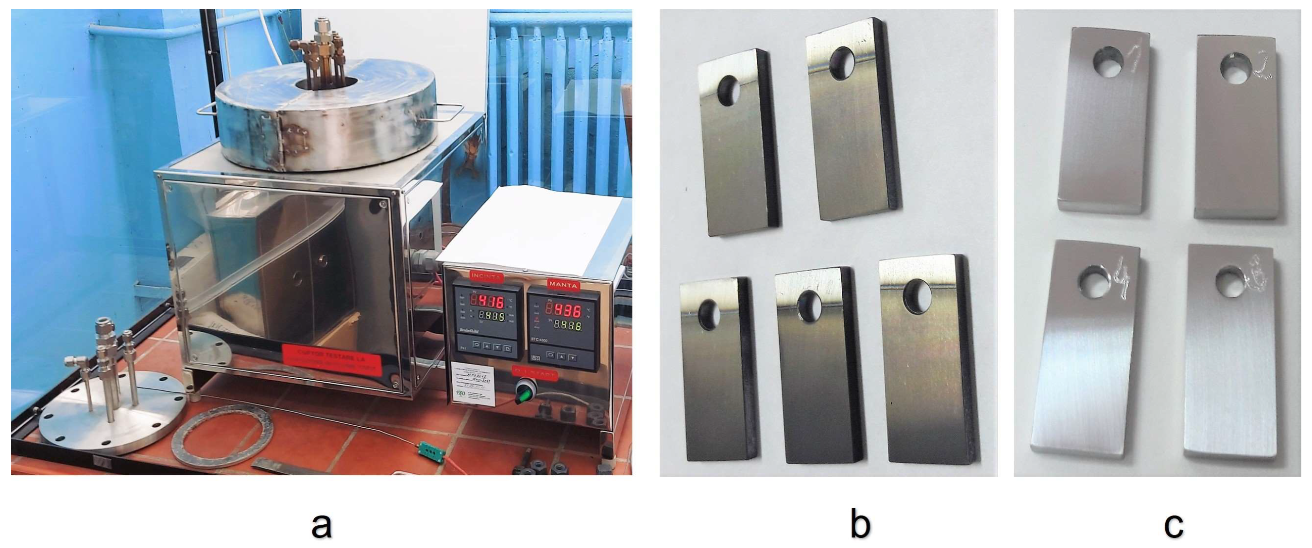
2.1. Preparation of Protective Coatings for Corrosion Tests
2.2. Corrosion Test in Stagnant Liquid Lead
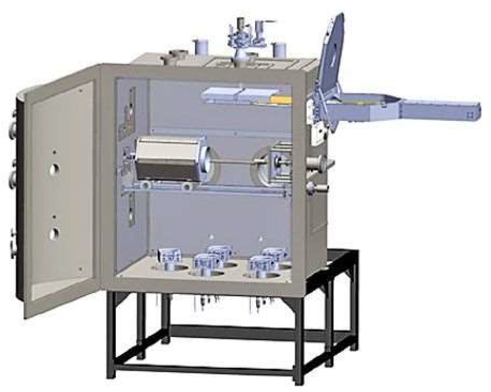
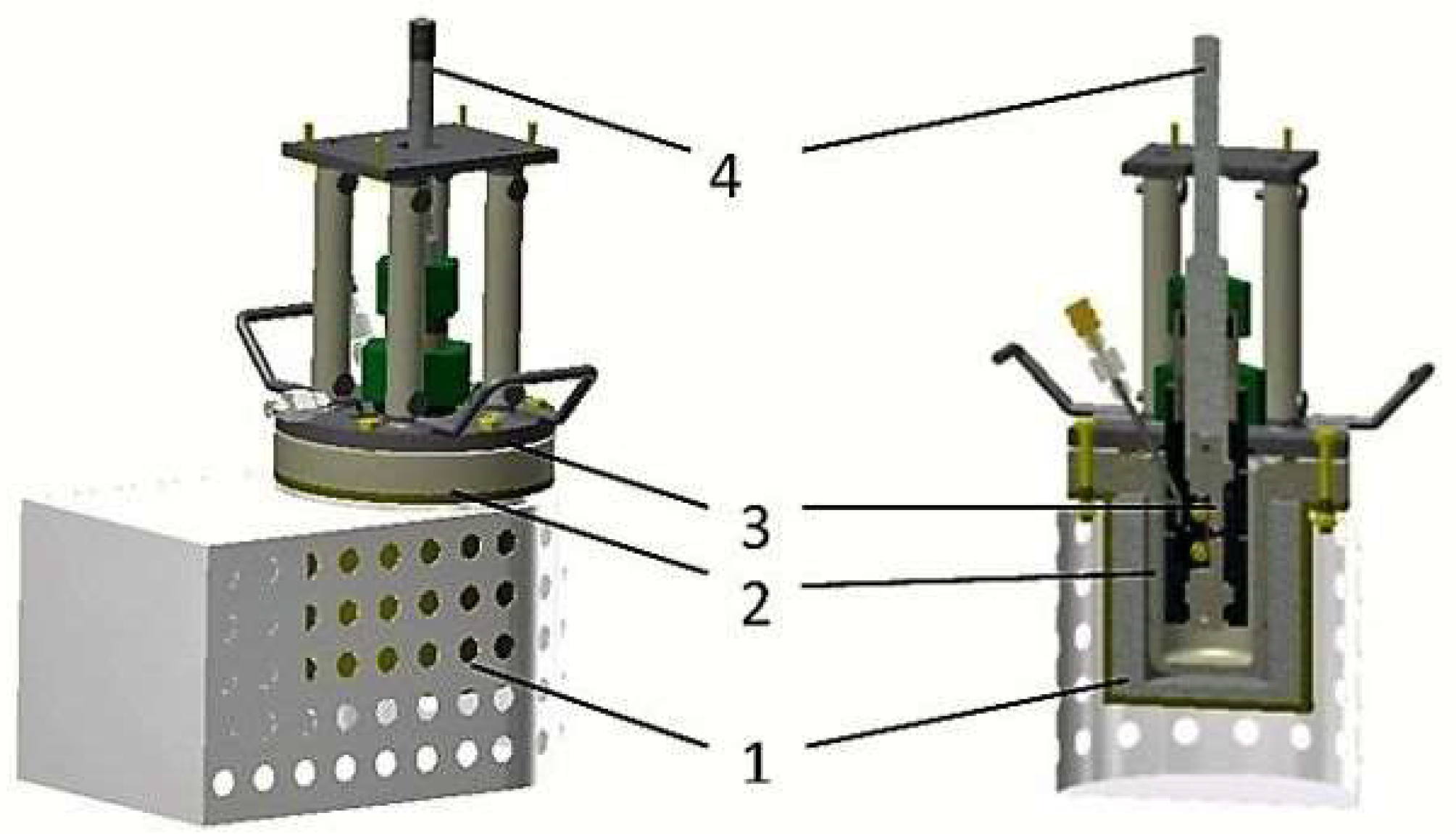
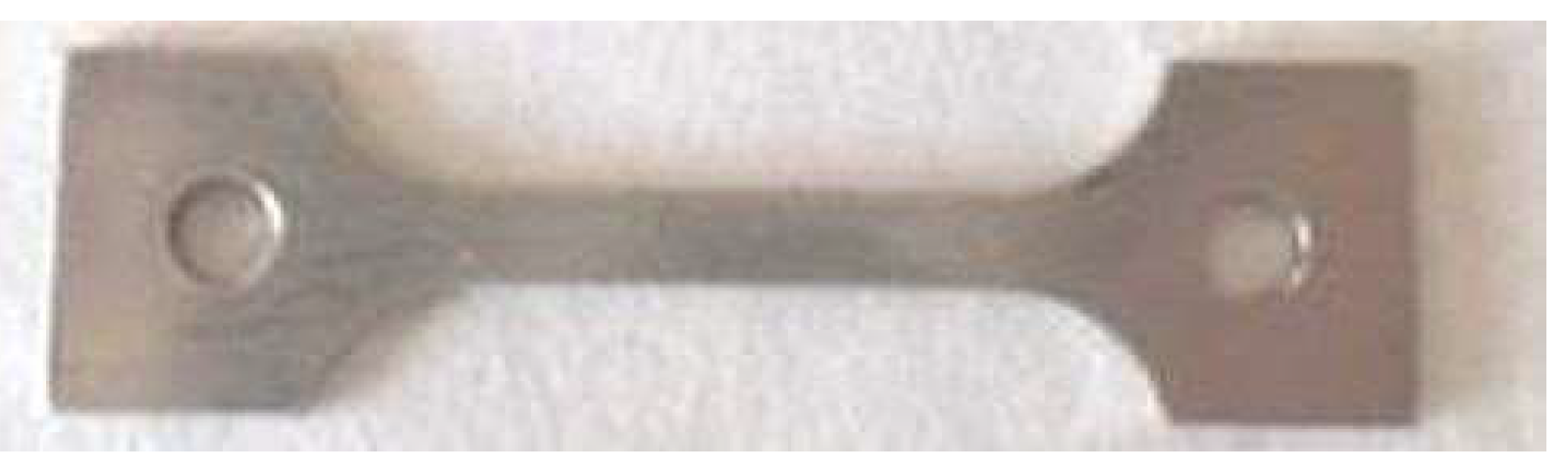
2.3. Testing Facility for Mechanical Tests in Liquid Lead
2.4. Characterisation Methods and Devices
3. Results and Discussion
3.1. Coating Layer Analysis
3.2. Corrosion Test
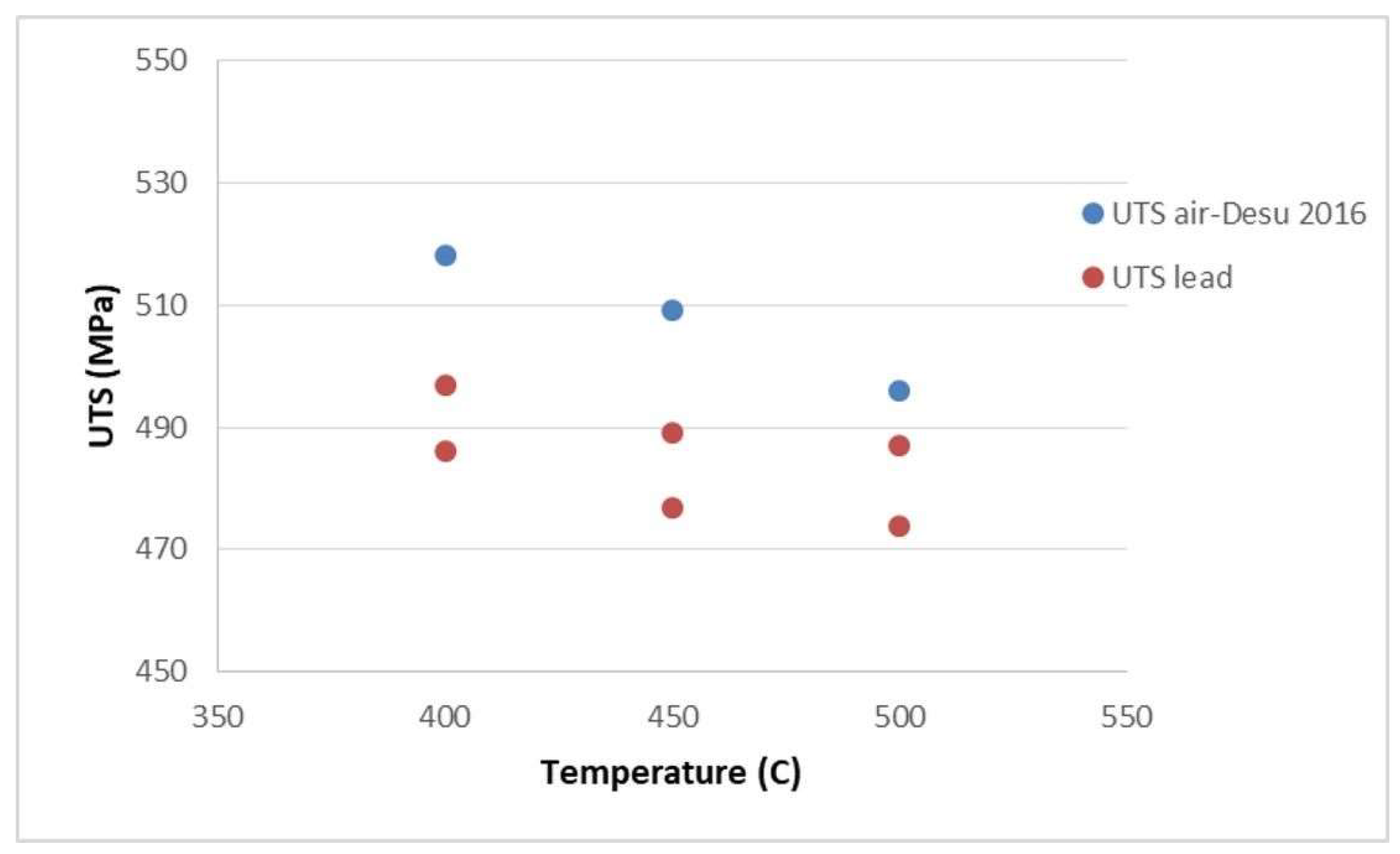
3.3. Tensile Behaviour of 316L Steel in a Liquid Lead Environment
4. Conclusions
Author Contributions
Funding
Institutional Review Board Statement
Informed Consent Statement
Data Availability Statement
Conflicts of Interest
References
- Petrescu, D.; Fulger, M.; Golgovici, F.; Demetrescu, I. Addressing some issues encountered in liquid lead corrosion tests of candidate materials for future nuclear reactors. UPB Sci. Bull. Ser. B 2022, 84, 89–97. [Google Scholar]
- Corwin, W.R.U.S. Generation IV Reactor Integrated Materials Technology Program. Nucl. Eng. Technol. 2006, 38, 591–618. [Google Scholar]
- Yvon, P. Structural Materials for Generation IV Nuclear Reactors 2016; Woodhead Publishing Series in Energy; Woodhead Publishing: Sawston, UK, 2016; ISBN 9780081009062. [Google Scholar]
- Frogheri, M.; Alemberti, A.; Mansani, L. The Advanced Lead Fast Reactor European Demonstrator (ALFRED). In Proceedings of the 15th International Topical Meeting on Nuclear Reactor Thermal—Hydraulics, Pisa, Italy, 12–17 May 2013. [Google Scholar]
- Zhang, J. A review of steel corrosion by liquid lead and lead-bismuth. Corros. Sci. 2009, 51, 1207–1227. [Google Scholar] [CrossRef]
- Gorynin, I.V.; Karzov, G.P.; Markov, V.G. Structural materials for atomic reactors with liquid metal heat-transfer agents in the form of lead or lead-Bismuth alloy. Met. Sci. Heat Treat. 1999, 41, 384–388. [Google Scholar] [CrossRef]
- Chen, X.; Yuan, Q.; Madigan, B. Long-corrosion behavior of martensitic steel welds in static molten Pb-17Li alloy at 550 °C. Corros. Sci. 2015, 96, 178–185. [Google Scholar] [CrossRef]
- Wang, J.; Lu, S.; Rong, L. Effect of silicon on the oxidation resistance of 9 wt.% Cr heat resistance steels in 550 °C lead-bismuth eutectic. Corros. Sci. 2016, 111, 13–25. [Google Scholar] [CrossRef]
- Martinelli, L.; Balbaud-Celerier, F.; Terlain, A.; Delpech, S. Oxidation mechanism of a Fe-9Cr-1Mo steel by liquid Pb-Bi eutectic alloy. Corros. Sci. 2008, 50, 2523–2536. [Google Scholar] [CrossRef]
- Hosemann, P.; Dickerson, R.; Dickerson, P. Transmission electron microscopy (TEM) on oxide layers formed on D9 stainless steel in lead bismuth eutectic (LBE). Corros. Sci. 2013, 66, 196–202. [Google Scholar] [CrossRef]
- Muller, G.; Heinzel, A.; Konys, J.; Schumacher, G.; Weisenburg, A. Behavior of steels in flowing liquid PbBi eutectic alloy at 420–600 °C after 4000–7200 h. J. Nucl. Mater. 2004, 335, 163–168. [Google Scholar] [CrossRef]
- Shroer, C.; Wedemeyer, O.; Novotny, J. Selective leaching of nickel and chromium from Type 316 austenitic steel in oxygen-containing lead-bismuth eutectic (LBE). Corros. Sci. 2014, 84, 113–124. [Google Scholar] [CrossRef]
- Yamaki, E.; Ginestar, K.; Martinelli, L. Dissolution mechanism of 316L in lead-bismuth eutectic at 500 °C. Corros. Sci. 2011, 53, 3075–3085. [Google Scholar] [CrossRef]
- Kondo, M.; Takahashi, M.; Suzuki, T.; Ishikawa, K.; Hata, K.; Qiu, S.Z.; Sekimoto, H. Metallurgical study on erosion and corrosion behaviors of steels exposed to liquid lead-bismuth flow. J. Nucl. Mater. 2005, 343, 349–359. [Google Scholar] [CrossRef]
- Del Giacco, M.; Weisenburger, A.; Müller, G. Fretting corrosion of steels for lead alloys cooled ADS. J. Nucl. Mater. 2014, 450, 225–236. [Google Scholar] [CrossRef]
- Van den Bosch, J.; Coen, G.; Hosemann, P.; Maloy, S.A. On the LME susceptibility of Si enriched steels. J. Nucl. Mater. 2012, 429, 105–112. [Google Scholar] [CrossRef]
- Gong, X.; Marmy, P.; Volodin, A.; Amin-Ahmadi, B.; Qin, L.; Schryvers, D.; Gavrilov, S.; Stergar, E.; Verlinden, B.; Wevers, M.; et al. Multiscale investigationof quasibrittle fracture characteristics in a 9Cr-1Mo ferritic-martensitic steelembrittled by liquid lead-bismuth under low cycle fatigue. Corros. Sci. 2016, 102, 137–152. [Google Scholar] [CrossRef]
- Jianu, A.; Müller, G.; Weisenburger, A.; Fazio, C.; Markov, V.G.; Kashtanov, A.D. Creep-to-rupture tests of T91 steel in flowing Pb-Bi eutectic melt at 550 °C. J. Nucl. Mater. 2009, 394, 102–108. [Google Scholar] [CrossRef]
- Weisenburger, A.; Mansani, L.; Schumacher, G.; Müller, G. Oxygen for protective oxide scale formation on pins and structural material surfaces in lead-alloy cooled reactors. Nucl. Eng. Des. 2014, 273, 584–594. [Google Scholar] [CrossRef]
- Asher, R.C.; Davies, D.; Beetham, S.A. Some observations on the compatibility of structural materials with molten lead. Corros. Sci. 1977, 17, 545–557. [Google Scholar] [CrossRef]
- Ejenstam, J.; Halvarsson, M.; Weidow, J.; Jönsson, B.; Szakalos, P. Oxidation studies of Fe10CrAl-RE alloys exposed to Pb AT 550 °C for 10000 h. J. Nucl. Mater. 2013, 443, 161–170. [Google Scholar] [CrossRef]
- Ejenstam, J.; Szakalos, P. Long term corrosion resistance of alumina forming austenitic stainless steels in liquid lead. J. Nucl. Mater. 2015, 461, 164–170. [Google Scholar] [CrossRef]
- Short, M.P.; Ballinger, R.G.; Hänninen, H.E. Corrosion resistance of alloys F91 and Fe-12Cr-2Si in lead-bismuth eutectic up to 715 °C. J. Nucl. Mater. 2013, 434, 259–281. [Google Scholar] [CrossRef]
- Rivai, A.K.; Takahashi, M. Corrosion investigations of Al-Fe-coated steels, high Cr steels, refractory metals and ceramics in lead alloys at 700 °C. J. Nucl. Mater. 2010, 398, 146–152. [Google Scholar] [CrossRef]
- Fetzer, R.; Weisenburger, A.; Jianu, A.; Müller, G. Oxide scale formation of modified FeCrAl coatings exposed to liquid lead. Corros. Sci. 2012, 55, 213–218. [Google Scholar] [CrossRef]
- García Ferré, F.; Mairov, A.; Iadiciccoa, D.; Vanazzi, M.; Bassini, S. Corrosion and radiation resistant nanoceramic coatings for lead fast reactors. Corros. Sci. 2017, 124, 80–92. [Google Scholar] [CrossRef]
- Kashkarov, E.; Afornu, B.; Sidelev, D.; Krinitcyn, M.; Gouws, V.; Lider, A. Recent Advances in Protective Coatings for Accident Tolerant Zr-Based Fuel Claddings. Coatings 2021, 11, 557. [Google Scholar] [CrossRef]
- Gavrilov, S.; Coen, G.; Van den Bosch, J. Mechanical Properties of Structural Materials in HLM. In Proceedings of the SEARCH Meeting, Pisa, Italy, 27 June 2012. [Google Scholar]
- Gómez-Briceño, D. Guideline Document for HLM Technology, Deliverable N. 25 VELLA; Ciemat: Madrid, Spain, 2009. [Google Scholar]
- Lorusso, P.; Bassini, S.; Del Nevo, A. GEN-IV LFR Development: Status & Perspectives. Prog. Nucl. Energy 2018, 105, 318–331. [Google Scholar] [CrossRef]
- Tudose, A.E.; Gologovici, F.; Anghel, A.; Manuela, F.; Demetrescu, I. Corrosion Testing of CrNx coated 310 H Stainless Steel under Simulated Supercritical Water Conditions. Materials 2022, 15, 5489. [Google Scholar] [CrossRef]
- Tudose, A.E.; Demetrescu, I.; Golgovici, F.; Fulger, M. Oxidation behavior of an austenitic steel (Fe, Cr and Ni), the 310 H, in a deaerated supercritical water static system. Metals 2021, 11, 571. [Google Scholar] [CrossRef]
- Wang, H.; Xiaoi, J.; Wang, H.; Chen, Y.; Yin, X. Corrosion Behavior and Surface Treatment of Cladding Materials Used in High-Temperature Lead-Bismuth Eutectic Alloy: A Review. Coatings 2021, 11, 364. [Google Scholar] [CrossRef]
- Kashkarov, E.; Sidelev, D.; Rombaeva, M.; Syrtanov, M.; Bleykher, G. Chromium coatings deposited by cooled and hot target magnetron sputtering for accident tolerant nuclear fuel claddings. Surf. Coat. Technol. 2020, 389, 125618. [Google Scholar] [CrossRef]
- Diniasi, D.; Golgovici, F.; Anghel, A.; Fulger, M.; Surdu-Bob, C.C.; Demetrescu, I. Corrosion Behavior of Chromium Coated Zy-4 Cladding under CANDU Primary Circuit Conditions. Coatings 2021, 11, 1417. [Google Scholar] [CrossRef]
- Nuclear Energy Agency. Corrosion protection in lead and lead-bismuth eutectic at elevated temperatures. In Handbook on Lead-Bismuth Eutectic Alloy and Lead Properties, Materials Compatibility, Thermal-Hydraulics and Technologies; OECD, Nuclear Science: Paris, France, 2015; pp. 631–632. [Google Scholar]
- Gong, X.; Chen, R.; Wang, Y. Microstructure and Oxidation Behavior of NiCoCrAlY Coating with Different Sm2O3 Concentration on TiAl Alloy. Front. Mater. 2021, 8, 710431. [Google Scholar] [CrossRef]
- Piticescu, R.; Urbina, M.; Rinaldi, A. Development of Novel Material Systems and Coatings for Extreme Environments: A Brief Overview. J. Miner. Met. Mater. Soc. 2019, 71, 683–690. [Google Scholar] [CrossRef]
- Inspection Certificate No. 783863/08.08.2017; Product 316L Steel; Saritas Celik Sanayi: Istanbul, Turkey, 2017.
- Ionescu, V.; Radu, V.; Nițu, A.; Ion, A.; Olaru, V.; Stoica, L. The Study of Mechanical Properties for Generation IV Candidate Materials by Tensile Tests; Internal Report RATEN ICN: Pitesti, Romania, 2018. [Google Scholar]
- Vykhodets, V.; Jarvis, E.; Kurennykh, T.; Beketov, I. Extreme deviations from stoichiometry in alumina nanopowders. Surf. Sci. 2014, 630, 182–186. [Google Scholar] [CrossRef]
- Di Gabriele, F.; Amore, S.; Scaiola, C. Corrosion behavior of 12Cr-ODS steel in molten lead. Nucl. Eng. Des. 2014, 280, 69–75. [Google Scholar] [CrossRef]
- Navas, M.; Hernandez, R. Compatibility of Structural Materials with Lead and Lead Bismuth Eutectic for CSP Applications. AIP Conf. Proc. 2018, 2033, 230009. [Google Scholar] [CrossRef]
- Vogt, J.-B.; Serre, I.P. A Review of the Surface Modifications for Corrosion Mitigation of Steels in Lead and LBE. Coatings 2021, 11, 53. [Google Scholar] [CrossRef]
- Cionea, C.; Abad, M.D.; Aussat, Y.; Frazer, D. Oxide scale formation on 316L and FeCrAl steels exposed to oxygen controlled static LBE at temperatures up to 800 °C. Sol. Energy Mater. Sol. Cells. 2016, 144, 235–246. [Google Scholar] [CrossRef]
- Anghel, M.E.; Marcu, M.; Banu, A.; Atkinson, I. Microstructure and oxidation resistance of a NiCrAlY/Al2O3-sprayed coating on Ti-19Al-10Nb-V alloy. Ceram. Int. 2016, 42, 12148–12155. [Google Scholar] [CrossRef]
- Li, B.; Gao, Y.; Li, C.; Guo, H. Tribocorrosion Properties of NiCrAlY Coating in Different Corrosive Environments. Materials 2020, 13, 1864. [Google Scholar] [CrossRef]
- Liu, X.; An, Y.; Li, S.; Zhao, X.; Hou, G. An assessment of tribological performance on NiCoCrAlYTa coating under corrosive environments. Tribol. Int. 2017, 115, 35–44. [Google Scholar] [CrossRef]
- Mythreyi, O.; Raja, A.; Nagesha, B. Corrosion Study of Selective Laser Melted IN718 Alloy upon Post Heat Treatment and Shot Peening. Metals 2020, 10, 1562. [Google Scholar] [CrossRef]
- Jam, A.; Derakhshandeh, S.; Pakseresht, A. Evaluation of microstructure and electrochemical behavior of dual-layer NiCrAlY/mullite plasma sprayed coating on high silicon cast iron alloy. Ceram. Int. 2017, 43, 14146–14155. [Google Scholar] [CrossRef]
- Miorin, E.; Montagner, F.; Zin, V.; Giuranno, D. Al rich PVD protective coatings: A promising approach to prevent T91 steel corrosion in stagnant liquid lead. Surf. Coat. Technol. 2019, 377, 124890. [Google Scholar] [CrossRef]
- ASTM E8/E8M-21; Standard Test Methods for Tension Testing of Metallic Materials. ASTM International: West Conshohocken, PA, USA, 2022.
- Cooper, A.; Brayshaw, W. Tensile Fracture Behavior of 316L Austenitic Stainless Steel Manufactured by Hot Isostatic Pressing. Metall. Mater. Trans. 2018, 49, 1579–1591. [Google Scholar] [CrossRef]
- Langdon, G.S.; Schleyer, G.K. Unusual strain rate sensitive behavior of AISI 316L austenitic stainless steel. J. Strain Anal. Eng. Des. 2004, 39, 71–86. [Google Scholar] [CrossRef]
- Desu, R.K.; Krishnamurthy, H.N.; Balu, A.; Gupta, A.K.; Singh, S.K. Mechanical properties of Austenitic Stainless Steel 304L and 316L at elevated temperatures. J. Mater. Res. Technol. 2016, 5, 13–20. [Google Scholar] [CrossRef]


| Elements% | ||||||||
|---|---|---|---|---|---|---|---|---|
| Fe | C | Cr | Ni | Mo | Mn | Si | P | S |
| Bal. | 0.02 | 17.1 | 10.1 | 2.03 | 0.9 | 0.47 | 0.033 | <0.001 |
| Yield strength | Rp0.2 = 306 MPa |
| Tensile strength | Rm = 604 MPa |
| Elongation | A5 = 59% |
| Hardness | 166 HBW |
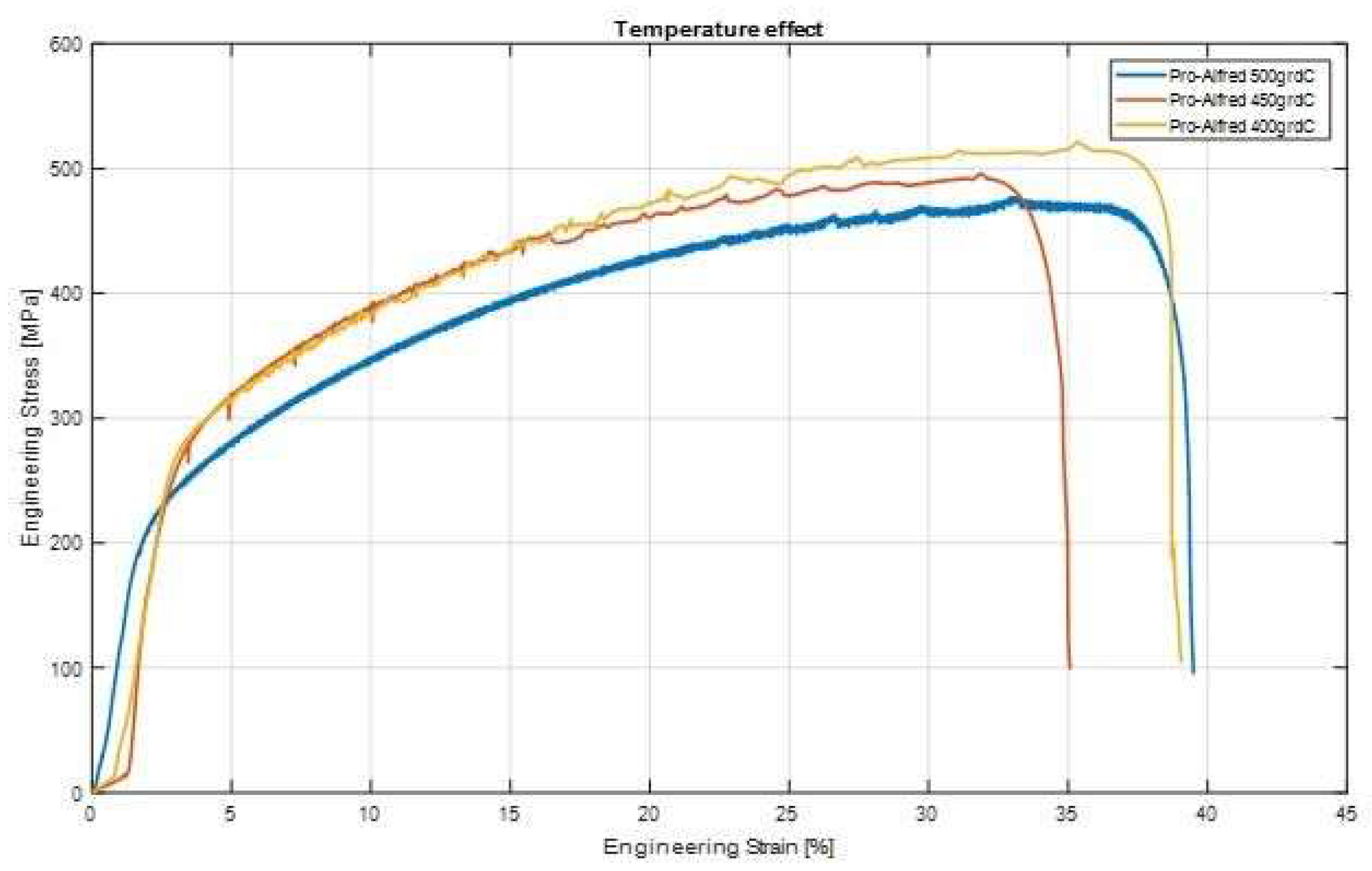
| No. | Specimen Cod | Testing Temperature [°C] | UTS [MPa] |
|---|---|---|---|
| 1. | Pro-Alfred S1 | 500 | 487 |
| 2. | Pro-Alfred S2 | 500 | 474 |
| 3. | Pro-Alfred S3 | 450 | 489 |
| 4. | Pro-Alfred S4 | 450 | 477 |
| 5. | Pro-Alfred S5 | 400 | 497 |
| 6. | Pro-Alfred S6 | 400 | 486 |
Disclaimer/Publisher’s Note: The statements, opinions and data contained in all publications are solely those of the individual author(s) and contributor(s) and not of MDPI and/or the editor(s). MDPI and/or the editor(s) disclaim responsibility for any injury to people or property resulting from any ideas, methods, instructions or products referred to in the content. |
© 2023 by the authors. Licensee MDPI, Basel, Switzerland. This article is an open access article distributed under the terms and conditions of the Creative Commons Attribution (CC BY) license (https://creativecommons.org/licenses/by/4.0/).
Share and Cite
Petrescu, D.; Nitu, A.; Golgovici, F.; Demetrescu, I.; Corban, M. Behaviour Aspects of an EB-PVD Alumina (Al2O3) Film with an Interlayer (NiCrAlY) Deposited on AISI 316L Steel Investigated in Liquid Lead. Metals 2023, 13, 616. https://doi.org/10.3390/met13030616
Petrescu D, Nitu A, Golgovici F, Demetrescu I, Corban M. Behaviour Aspects of an EB-PVD Alumina (Al2O3) Film with an Interlayer (NiCrAlY) Deposited on AISI 316L Steel Investigated in Liquid Lead. Metals. 2023; 13(3):616. https://doi.org/10.3390/met13030616
Chicago/Turabian StylePetrescu, Daniel, Alexandru Nitu, Florentina Golgovici, Ioana Demetrescu, and Mircea Corban. 2023. "Behaviour Aspects of an EB-PVD Alumina (Al2O3) Film with an Interlayer (NiCrAlY) Deposited on AISI 316L Steel Investigated in Liquid Lead" Metals 13, no. 3: 616. https://doi.org/10.3390/met13030616
APA StylePetrescu, D., Nitu, A., Golgovici, F., Demetrescu, I., & Corban, M. (2023). Behaviour Aspects of an EB-PVD Alumina (Al2O3) Film with an Interlayer (NiCrAlY) Deposited on AISI 316L Steel Investigated in Liquid Lead. Metals, 13(3), 616. https://doi.org/10.3390/met13030616