Abstract
In this research, corrugated Mg/Al clad sheet with good interface bonding was prepared with a rolling mill of upper corrugated roll and a lower flat roll under the conditions of 35% reduction and 400 °C. The mechanical properties of the corrugated Mg/Al clad sheet were studied using the transverse tensile test, Vickers microhardness and as well as its bending properties. Moreover, the interface bonding mechanism of the corrugated clad sheet was researched through three-dimensional contour analysis. The results showed that the UTS at the trough position was the highest (~296 MPa), and that the peak position was the lowest (~257 MPa). The maximum fracture EL at the peak position was ~13.4%, while the minimum fracture EL at the trough position was ~10.6%. In the transverse tensile process, the interface cracked first due to the uneven stress distribution in the matrixes. Then, the Mg sheet broke, and finally the Mg/Al clad sheet failed with final fracturing of the Al sheet. The microhardness of interface metal Al at the four positions was higher than that of the interface metal Mg, which was closely related to the dislocation strengthening of the Al sheet. The interface bonding mechanism of the corrugated Mg/Al clad sheet could be divided into four stages: extrusion deformation, rubbing fracture, compound extension and compound completion.
1. Introduction
With the rapid development of aerospace, electronic technology and automobile manufacturing, traditional single metal material is often affected by the lack of comprehensive performance, high manufacturing costs and lack of natural resources; hence, it is difficult to fully meet the use demand. Therefore, dissimilar metals with different characteristics are combined through mechanical or metallurgical combination to make clad sheets to meet the performance requirements [1,2,3]. The prepared clad sheets have excellent properties of their component materials, including simple preparation methods, high bonding strength and low cost [4].
Lightweight, high-strength and excellent corrosion resistant Mg/Al clad sheets were prepared by combining Mg and Al sheets [5,6]. This can not only reduce the weight, but also ensure its use performance. Mg/Al clad sheets have good application prospects in aerospace, high-speed rail, marine transportation, automotive industry and other fields [7,8,9]. Mg/Al clad sheets can give full play to the advantages of their component metals in performance and function. They represent one of the important directions for the development from traditional single materials to high-tech composite materials, and have important engineering application value [10].
At present, there are many methods used to prepare Mg/Al clad sheets, such as traditional rolling, explosive welding, asynchronous rolling, diffusion compositing, accumulative roll bonding, extrusion compositing, friction stir welding, cast-rolling compositing, etc. These methods can be divided into solid–solid bonding, solid–liquid bonding and liquid–liquid bonding, according to the different initial physical states of the substrate and cladding plate. Mg/Al clad sheets manufactured through a rolling bonding method have the advantages of simple operation, high production efficiency, low costs and easy-to-realize large-scale industrial production, so they have been focused on by many scholars [11]. Nie et al. [12] prepared Al/Mg/Al three-layer laminates using a four-pass hot rolling method at a temperature of 400℃ and a reducton of 71%. Furthermore, the laminates were annealed at 200 °C for 1 h. The results showed that the Mg grains equiaxed due to recrystallization, while the Al grains had a deformed structure. Meanwhile, the tensile properties along the rolling direction of these Al/Mg/Al three-layer laminates were measured; it was found that the tensile strength was 230 MPa [13]. However, the Mg/Al clad sheet prepared by traditional flat rolling had serious shape warpage and low bonding strength. The main reasons for these problems were attributed to the following points: (1) In the rolling process, it was necessary to have a large reduction to obtain an Mg/Al clad sheet with tight interface bonding; (2) there was serious deformation disharmony between the Mg sheet with its relatively brittle characteristics and the Al sheet with its good plastic deformation ability. Using high reduction easily reduces the service life of the rolling mill. Incoordination deformation between dissimilar metals leads to serious warpage of the rolled plate, which is not conducive to the subsequent forming.
The strong plastic deformation rolling process is widely used in the preparation of laminates. Chang et al. [14,15] prepared Mg/Al multilayer composites by the accumulative roll bonding method. The mechanical properties were improved by applying cumulative strain to the plates to achieve interface metallurgical bonding and grain refinement. Thangapandian et al. [16] and Bhovi et al. [17] studied the effects of a repeated corrugation and straightening (RCS) method on grain refinement of Al–Mg and Al–Mg–Sc alloy sheets. It was found that the selection of an appropriate corrugation morphology was very important for grain refinement. Corrugation-flat rolling (CFR) is a new rolling technology for laminated metal composite plates. Wang et al. [18] produced Cu/Al clad sheet using the CFR process at room temperature. The results showed that a corrugated interface was formed, and the interfacial metal grains were significantly refined, resulting in excellent tensile properties. In addition, Wang et al. [19] prepared an Mg/Al clad sheet using the CFR process at 400 °C. The results showed that the corrugated roll could produce uneven shear deformation at the Mg substrate and the interface, which can lead to grain refinement. Furthermore, the deformation ability of hard-to-deform metal Mg was promoted, and the coordination deformation ability between the Mg sheet and the Al sheet was improved. Interface metallurgical bonding was realized and the mechanical properties of the laminates were improved.
The CFR process is a kind of non-uniform plastic deformation process under periodic load, and the interface metal plastic deformation behavior is relatively complex. The mechanical properties of the interface metal and interface bonding mechanism of the corrugated Mg/Al clad sheet at four typical positions (front waist, peak, back waist and trough) have not been systematically studied. In view of this, this study observed the interface microstructure through SEM observation and EBSD analysis. The tensile properties, microhardness and bending properties of the Mg/Al clad sheet at typical positions were analyzed. The tensile shear section morphology of the interface at different positions was analyzed to study the metal adhesion characteristics.
2. Experimental Procedure
2.1. Materials
AZ31B wrought Mg alloy sheet has high strength, is lightweight and has good machinability. 5052 Al alloy sheet has good formability and corrosion resistance. Therefore, these two materials were selected as the original materials in this research. In the experiment, Mg sheet was used as the cladding plate and Al sheet as the substrate. The size of the Mg and Al sheets were 100 mm × 60 mm × 2 mm. The chemical composition of the AZ31B Mg sheet and the 5052 Al sheet are shown in Table 1.

Table 1.
Chemical compositions of AZ31B Mg sheet and 5052 Al sheet (wt. %).
2.2. Billet Preparation
The bonding surfaces of the original Mg and Al sheets were polished using a wire brush. Then, the polished sheets were stacked. Figure 1 displays the topography, three-dimensional outline and height nephogram of the Mg and Al sheets after grinding, in which red represents the high area and blue represents the low area. It can be seen from Figure 1a,d that the polished surfaces of the Mg and Al sheets showed obvious scratches. The maximum height of the Mg surface was 13.184 μm (Figure 1b). The height distribution was relatively uniform, and the surface roughness of the polished Mg was 2.68 μm. From Figure 1e, the maximum height of the Al surface was 12.505 μm. The surface roughness of the polished Al sheet was 2.95 μm. In order to prevent deviations of the Mg sheet and the Al sheet during the rolling process, one end of the sheet was bound with Al wire, and the other end was riveted with Al nails to make an Mg/Al billet.
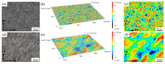
Figure 1.
Topography and three-dimensional profiles of Mg and Al sheets after grinding with a wire brush: (a–c) Mg sheet; (d–f) Al sheet.
2.3. Heating before Rolling
The Mg/Al billet was placed into a tubular heating furnace and argon protection for heating, with a temperature of 400 °C and a holding time of 15 min. There was a great influence of temperature on the plastic deformation ability of the Mg sheet. The non-basal slips of the Mg alloy were easily activated, and the plastic deformation ability greatly improved when the temperature was 225 °C~400 °C. Meanwhile, the deformation resistance of the Mg sheet decreased with increasing temperature. Therefore, the temperature selected in this study was 400 °C.
2.4. Corrugated Rolling Process
A rolling mill with an upper corrugated roll and a lower flat roll was used for the corrugated rolling process. The reduction was 35% and the rolling speed was 0.12 m/s. When the reduction was 35%, the overall shape of the corrugated Mg/Al clad sheet was flat and straight, which was conducive to the subsequent forming. Therefore, 35% reduction was selected for the corrugated rolling process. During the rolling process, the Mg sheet contacted with the upper corrugated roll, and the Al sheet contacted with the lower flat roll without lubrication. The average diameter of the corrugated roll and the diameter of the flat roll was 150 mm. The surface curve of the corrugated roll was a sine curve, with an amplitude of 0.5 mm and a corrugation number of 100. The experimental two-high mill and the corrugated roll are shown in Figure 2. The corrugated Mg/Al clad sheet with its corrugated surface was obtained after the corrugated rolling process. Figure 3 displays the four typical positions of the corrugated Mg/Al clad sheet, namely front waist, peak, back waist and trough.
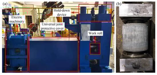
Figure 2.
Experimental equipment: (a) two-high mill; (b) corrugated roll.
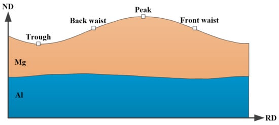
Figure 3.
Four positions of the corrugated Mg/Al clad sheet.
2.5. Microstructure Characterization and Mechanical Properties Tests
A scanning electron microscope (SEM) equipped with electron backscatter diffraction (EBSD) techniques (model: JSM-IT500, JEOL Ltd., Japan) was used to observe the interface microstructure of the corrugated Mg/Al clad sheet. The observation surface of the sample was rolling direction (RD) × normal direction (ND), and the sample size was 8 mm × 6 mm (RD × TD). The voltage was 15~20 kV, and the working distance was 10~15 mm when using the scanning electron microscope for characterization. The surface of the EBSD sample was polished and treated with argon ion precision etching technology. During the observation, the sample tilt was 70°, the working distance was 15 mm; the test voltage was 20 kV, and the scanning step was 0.6 μm. Finally, the EBSD test data were processed with Channel 5 software. Three-dimensional profile measurements of the interface fracture sections at different positions were carried out through the shape analysis laser microscope (model: VK-X1000, KEYENCE, Japan).
An Instron 5969 universal tensile testing machine (Instron Ltd., Norwood, MA, USA) was used to measure the tensile properties of the corrugated Mg/Al clad sheet along transverse direction (TD) at a speed of 0.5 mm/min. Dog-bone tensile specimens with a gauge length of 20 mm and gauge width of 3 mm were cut using a wire cutting machine, and the specimens were polished until a mirror effect was achieved. In order to research the fracture sequence of the interface and matrix during the tensile process of the corrugated Mg/Al clad sheet, a digital image correlation (DIC) system was used to monitor the tensile process. The microhardness of the matrixes was tested with a micro Vickers hardness tester (model: HVT-1000, Sichangyue Optical Instrument Co., Ltd., Shanghai, China). The test force was 100 g and the test force holding time was 10 s. Three points were selected from each position, and then the average value was taken as the final hardness value of this position. The Instron 5969 universal tensile testing machine was used to carry out three-point bending tests on the corrugated Mg/Al clad sheet. The length of the specimen was 45 mm and the width was 3 mm. The bending speed was 2 mm/min and the span was 30 mm.
3. Results and Discussion
3.1. Interface Morphology
The interfaces’ SEM morphology can be observed in Figure 4. It can be seen from Figure 4 that the interfaces at the four positions were well combined, and there were no holes, cracks and other defects at the interfaces. Figure 5 shows the interface inverse pole figure (IPF) of the four typical positions of the corrugated Mg/Al clad sheet. The upper metal was AZ31B Mg sheet and the lower metal was 5052 Al sheet. As can be seen from Figure 5, a large number of fine equiaxed grains and a small number of coarse grains coexisted on the Mg side at these four positions. Moreover, fine Mg grains were found at the coarse grain boundary, which were due to the dynamic recrystallization during the corrugated rolling process. For the Al side, the Al grains were obviously elongated at the four positions, and fine grains were also observed at grain boundaries of the elongated grains. The reason for this phenomenon is the occurrence of partial dynamic recrystallization [20]. After corrugated rolling, the matrix metals had obvious grain refinement.
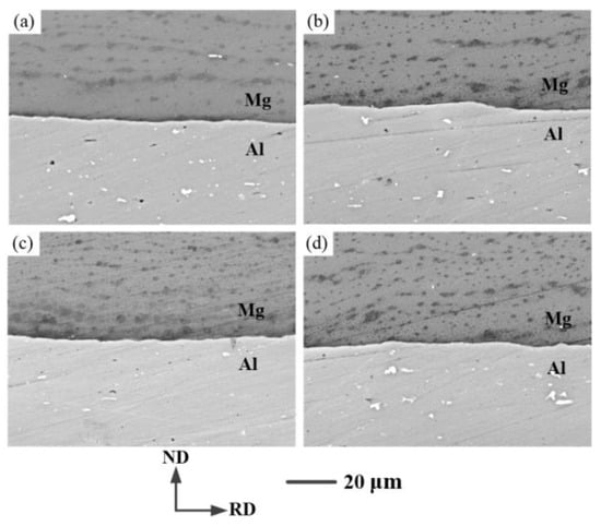
Figure 4.
Interface SEM images of the corrugated Mg/Al clad sheet: (a) front waist, (b) peak, (c) back waist, (d) trough.
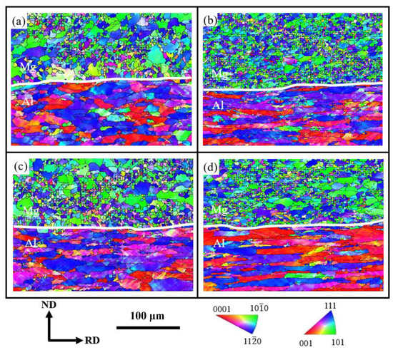
Figure 5.
Interface IPF images of the corrugated Mg/Al clad sheet: (a) front waist; (b) peak; (c) back waist; (d) trough.
During the corrugated rolling process, the interface metals at the peak position were subjected to relatively high shear stress, which promoted grain refinement. The temperature of Mg dynamic recrystallization can be decreased, and the dynamic recrystallization process can be accelerated with higher compressive stress at the trough position. Meanwhile, strong plastic deformation can provide a driving force for grain breakage and recrystallization, which is conducive to the formation of finer grain structure [21]. Compared with the back waist position, Mg grains at front waist position formed more fine grains in the severe deformation process. The grain refinement degree of the matrix metal of the corrugated Mg/Al clad sheet was higher. Strong plastic deformation can increase the dislocation density. The metal Al with high fault energy is prone to cross slip and climb of dislocations, which conforms to the dislocation movement conditions required for dynamic recovery of Al alloy.
3.2. Mechanical Properties of the Corrugated Mg/Al Clad Sheet
3.2.1. Tensile Properties
Figure 6 shows the transverse tensile properties of the corrugated Mg/Al clad sheet at room temperature, and the sampling positions are shown in the embedded diagram in Figure 6a. It can be seen from Figure 6 that the ultimate tensile strength (UTS) of the corrugated Mg/Al clad sheet at the trough position was the highest, reaching ~296 MPa. This value was significantly higher than the UTS of the original Mg sheet (~284 MPa) and the original Al sheet (~217 MPa). Moreover, the minimum UTS at the peak position was ~257 MPa. The front waist (~276 MPa) and the back waist (~272 MPa) values were in the middle. The difference between the minimum and maximum values of the transverse UTS at the four positions was ~39 MPa. The yield strength (YS) of the clad sheet at the trough position was also the highest (~223 MPa), and the minimum YS at the peak position was ~173 MPa. On the contrary, the fracture elongation (EL) of the Mg/Al clad sheet at the peak position was the largest, reaching ~13.4%, and the minimum at the trough position was ~10.6%. Nevertheless, the fracture EL of the corrugated Mg/Al clad sheet at the four positions was higher than that of the original Mg sheet (~24%) and the original Al sheet (~18%). This was caused by the obvious work-hardening phenomenon of the clad sheet after the corrugated rolling process. During the tensile process, the stress of the Mg/Al clad sheet at these four positions decreased after the strain reached a certain value, which was due to the delamination phenomenon at the Mg/Al interface.
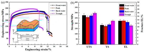
Figure 6.
Transverse tensile properties of the corrugated Mg/Al clad sheet: (a) stress–strain curves; (b) properties histogram.
The greater the plastic deformation of the metal, the more obvious the work hardening. Furthermore, the higher the strength, the worse the plasticity. The UTS and YS of the Mg/Al clad sheet at the trough position were the highest, while the fracture EL was the lowest, which is consistent with the work hardening behavior of the metal after strong plastic deformation. The ratio of yield strength to ultimate tensile strength (YS/UTS) can affect the plasticity of the clad sheet. The greater the YS/UTS, the worse the plasticity. Table 2 displays the data statistics of the transverse tensile properties of the corrugated Mg/Al clad sheet. It can be seen from Table 2 that the YS/UTS of the clad sheet at trough position reached 0.75, which was the largest of the four positions. That is, the UTS and YS were higher at the trough position, while the fracture EL was lower. The fracture EL of the Mg/Al clad sheet at the peak position was the highest among the four positions, which is due to the fact that the reduction in the corrugated roll acting on the peak metal was the lowest.
Table 2.
Transverse tensile properties statistics at four positions of the corrugated clad sheet.
Figure 7 exhibits the macro tensile fracture morphologies of the corrugated Mg/Al clad sheet along the TD. From Figure 7a, it can be seen that the Mg plate at the four positions displayed brittle fracture with a deflection of ~45° from the TD, while the Al plate showed necking due to its good plasticity. It should be noted that the interface delamination appeared near the fracture. Taking the clad sheet at the front waist position as an example, DIC strain analysis was performed on the tensile fracture process, as shown in Figure 7b–f. At the initial tensile stage, the Mg/Al clad sheet showed zero strain. As the tensile process proceeded, stress concentration occurred in the Mg sheet, but it did not break at this time. The uneven stress distribution on both sides of the Mg and Al sheets led to interface cracking, which was manifested as a slight drop in tensile stress on the tensile curve. Then, the Mg sheet broke quickly and the stress dropped sharply due to stress concentration and interfacial cracking. During the tensile process, the Al sheet necked and continued to deform after the Mg sheet broke. Eventually, the Mg/Al clad sheet failed completely.
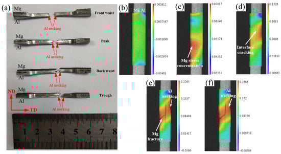
Figure 7.
Tensile fracture of the corrugated clad sheet: (a) macroscopic fracture; (b–f) DIC strain analysis of the front waist clad sheet in tensile fracture process.
Figure 8 is the SEM image of the tensile fracture morphologies of the corrugated Mg/Al clad sheet. It can be seen that obvious delamination occurred at the interface of the Mg/Al clad sheet at the four positions. The dimples on the Mg side were small and shallow, mostly cleavage planes, corresponding to the brittleness characteristic. The Mg sheet was the first to fracture due to its inherent brittleness, which is consistent with the stress drop in the engineering stress–strain curve. Numerous dimples were observed on the Al side, which indicated that the Al sheet retained relatively excellent extension properties. It is worth noting that the dimples at the Al fracture surface were both large and deep at the peak position, which corresponded to the longest fracture elongation.
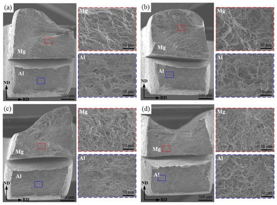
Figure 8.
Tensile micro fractures of the corrugated clad sheet: (a) front waist; (b) peak; (c) back waist; (d) trough.
3.2.2. Microhardness
Figure 9 shows the Vickers hardness of the interface matrixes at the four positions of the corrugated Mg/Al clad sheet. From Figure 9, it can be seen that the microhardness difference between these four positions of the matrixes was small. The microhardness of the Mg sheet at the peak position was the largest (~58 HV), and that at the back waist was the smallest (~55 HV). The hardness of the Al sheet at the peak position was the largest among the four positions, reaching ~68 HV, and that at the front waist was the smallest (~64 HV).
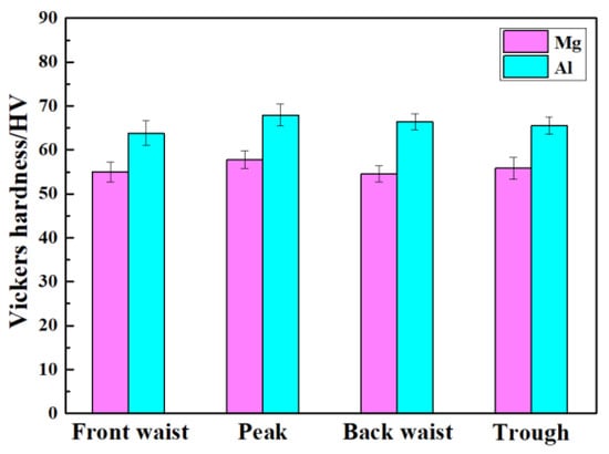
Figure 9.
Vickers hardness at interface metals of the corrugated clad sheet.
Although the reduction was the lowest at the peak position, the microhardness of the Mg sheet and the Al sheet was the highest. The shear deformation at the peak position can improve the microhardness of matrixes. The microhardness of the Al sheet was higher than that of the Mg sheet at the four positions, which is largely related to the dislocation strengthening of the Al alloy. The processing deformation was produced in the 5052 Al sheet during the rolling process, and the dislocation density increased. Dislocation entanglement was formed by dislocation interaction, resulting in dislocation movement being blocked and the plate gradually hardening. In addition, the microhardness of the Al sheet at the trough position was lower than that at the peak position, which was due to the combined action of heat being released by plastic deformation and high temperature rolling at the trough position.
Kernel average misorientation (KAM) is an important method to measure metal dislocation density [22]. It can quantitatively represent the average misorientation difference angle between a given point and its neighboring points belonging to the same grain, which is related to the plastic strain inside the material. According to the strain gradient theory [23], KAM can used to estimate the density of geometrically necessary dislocation (GND) [23,24]. The relationship between GND density and KAM is shown as follows:
In this equation, represents the density of geometrically necessary dislocation (m−2). represents the average angle of the local misorientation difference calculated from the KAM data (°). represents the EBSD analysis step size, 600 nm in this study. Finally, represents the Burgers vector (Mg is 0.321 nm [25], and Al is 0.286 nm [26]).
The KAM maps and the corresponding distribution curve of the matrixes were obtained via EBSD technology at the four positions of the corrugated Mg/Al clad sheet. As shown in Figure 10, blue indicates the low dislocation density and red indicates the high dislocation density. According to Equation (1), GND density distribution curves of the matrixes at the four positions were obtained, as shown in Figure 11.
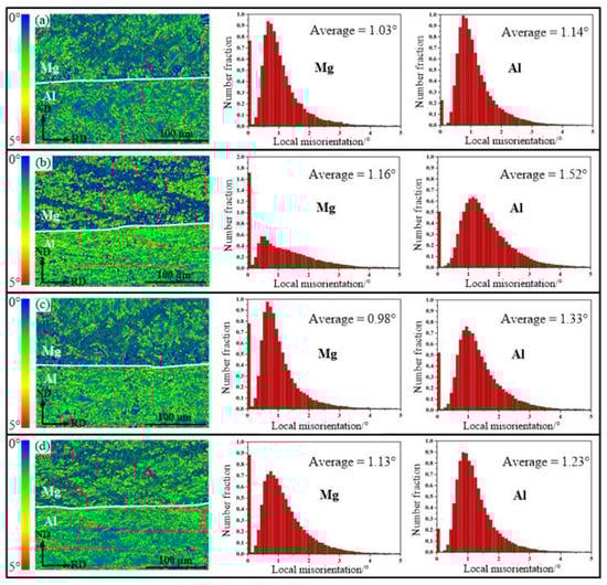
Figure 10.
KAM maps and corresponding distributions of the corrugated clad sheet: (a) front waist; (b) peak; (c) back waist; (d) trough.

Figure 11.
GND density distribution at four positions of the corrugated clad sheet: (a–d) Mg side; (e–h) Al side.
In Figure 10, the Mg side contains blue grains, which belong to the low dislocation density region and were mainly caused by a dynamic recrystallization phenomenon. In addition, the high dislocation density was mainly distributed at the boundary of the deformed grains, while the low dislocation density was mainly distributed inside the grains; this is due to the dislocation movement along the grain boundary when the grain boundary slipped. During the deformation process, a large number of dislocations proliferate and reproduce, which subsequently reach grain boundaries by slipping and climbing, thus preventing dislocations movement. It can be seen from Figure 10 and Figure 11 that the mean values of the KAM (1.16° of Mg, 1.52° of Al) and GND density (2.29 × 10¹⁴ m−2 of Mg, 3.11 × 10¹⁴ m−2 of Al) at the peak position were the largest for both the Mg and Al matrixes. This shows that large stresses and strains were applied to the vertical direction of the trough metal during the corrugated rolling process. With the increase in metal deformation at the trough position, the strain energy accumulated during the rolling process was effectively released by recovery or recrystallization, which led to a decrease in the strain storage energy after rolling [27]. The metals generated dislocation entanglement and rearranged to form a dislocation wall, and then evolved into low-angle grain boundaries (LAGBs). The strain mainly accumulated near the grain boundaries. The increase in dislocation density at the peak metal after the corrugated rolling helped to improve the microhardness of the plate, which also corresponded to the microhardness distribution shown in Figure 9. At the same position of the corrugated Mg/Al clad sheet, the average KAM value of the Al sheet was higher than that of the Mg sheet, so the hardening of the Al sheet was higher than that of the Mg sheet. The average KAM value of the Mg sheet at the trough position was 1.13°, which was higher than that of the front waist and back waist positions. However, the average KAM values of the Mg sheet at these four positions showed little difference, which was because numerous dynamic recrystallized Mg grains had a low local misorientation difference. In conclusion, dislocation strengthening and grain refinement are helpful to improve the microhardness of Mg and Al matrixes. However, the strengthening mechanism of the corrugated Mg/Al clad sheet at the peak position was mainly dislocation strengthening, while the sheet at the trough position was mainly grain boundary strengthening.
3.2.3. Bending Properties
Figure 12 shows the transverse three-point bending curve and the macro morphology after bending at the peak and trough positions of the corrugated Mg/Al clad sheet. The Mg sheet was in contact with the indenter during the bending process. As can be seen from Figure 12a, the maximum stress of the peak clad sheet in the bending process was ~451 MPa, which was less than that at the trough position (~673 MPa). In the bending experiment, the metal at the peak position showed a stress drop when the strain was ~14.3%, which was manifested as the metal Mg appearing cracked during extrusion. However, the stress at the trough position was continuous, and there was no dramatic load drop phenomenon, which indicated that the trough metal Mg did not crack during the bending process. It is noteworthy that the interfaces at the peak and trough positions were well combined. There was no delamination during the bending process and no crack and fracture in the Al side. The appearance of cracking on the Mg side at the peak position was due to the metal accumulation phenomenon occurring in the bending process. Corrugated roll can impose shear deformation on the Mg sheet and Al sheet, and improve their coordination deformation abilities. Moreover, when the strain was coordinated in the thickness direction, the crack generation of Mg was hindered. The good bending property at the trough position can be attributed to the excellent deformation coordination between the Mg layer and the Al layer.
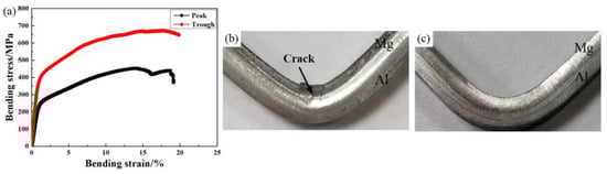
Figure 12.
Transverse bending properties of the corrugated clad sheet: (a) bending stress–strain curves; (b) peak morphology after bending; (c) trough morphology after bending.
3.3. Interface Bonding Mechanism
In order to further analyze the cross-sectional characteristics of the corrugated Mg/Al clad sheet at different positions, three-dimensional contour measurement was used to analyze the cross-section. Figure 13 shows the three-dimensional profile, the height cloud map and the roughness curve of the line in the height cloud map of the cross-section of the Al matrix. Red represents the high areas, and blue represents the low areas. Table 3 shows the section roughness statistics of the Al matrix. At the front waist position, the maximum height of the Al side reached 40.397 μm. Furthermore, a convex morphology resembling a “small bamboo shoot” was observed, which was scattered on the Al side. It can be inferred that these “bamboo shoots” may have been metal Mg left behind after the tear process. Scattered red areas can also be seen in the height cloud map in Figure 13b. The line roughness (Ra) in the height cloud map was 4.41 μm. Due to the high compressive stress on the front waist metal, the metal Mg adhered to the Al matrix during the tear process, resulting in local high region morphology. The value of Ra did not reflect the overall roughness, due to the uneven metal distribution in the cross-section. Therefore, the surface roughness (Sa) of the cross-section was measured, and the result was 3.99 μm.
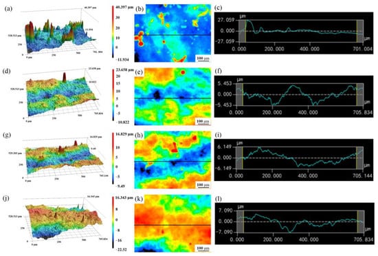
Figure 13.
Three-dimensional profile of Al cross-section: (a–c) front waist; (d–f) peak; (g–i) back waist; (j–l) trough.
Table 3.
Roughness statistics of Al matrix fracture surfaces.
At the peak position, the maximum height of the cross-section on the Al side reduced to 23.658 μm, which is due to single higher area. Figure 13d mainly shows the distribution morphology of Al side, but there are also individual high areas. The force of the peak metal is small and the content of metal Mg extrusion into the Al matrix is less. Sa value of the cross-section and the Ra value of the peak Al matrix are 3.16 μm and 2.14 μm, respectively. Similar to the three-dimensional contour of the peak position, there are also individual convex areas at the back waist position (Figure 13g). The maximum height continues to decrease to 16.829 μm, but the Sa value and Ra value increase to 3.39 μm and 2.41 μm, respectively, compared with the peak position. The maximum height of the Al matrix cross-section at trough position drops to 16.343 μm (Figure 13j). Nevertheless, the cross-section of the Al matrix exhibited a high regional distribution, shown in red. Under the condition of high reduction at the trough position, the bulk distribution of metal Mg appeared in the Al matrix, which corresponded to the formation of homogeneously dispersed high regions on the three-dimensional contour. A large area of metal Mg fracture can cause ups and downs in the cross-section. The Sa value in Figure 13j significantly increased to 4.43 μm, indicating that the fracture of the Mg trough improved the section roughness. By analyzing the change in the three-dimensional contour and surface roughness of the cross-section, the interface bonding of the corrugated Mg/Al clad sheet at different positions was indirectly reflected.
Figure 14 shows the three-dimensional profile, the height cloud map, and the roughness curve of the line in the height cloud map of the cross-section of the Mg matrix. Table 4 shows the section roughness statistics of the Mg matrix at the four positions. The maximum height of the Mg side cross-section at the front waist position was 12.397 μm, and no local high point was found. The Sa of the three-dimensional profile and the Ra in the height cloud map were 3.21 μm and 1.66 μm, respectively. Local high points were found in the Mg matrix cross-section of the peak and back waist positions, which were caused by tearing of the interfacial adhesive metal Mg. According to Table 4, the Ra value and the Sa value of the Mg matrix at the peak position were 3.01 μm and 2.8 μm, respectively, and those at the back waist position were 1.84 μm and 3.12 μm, respectively. The Ra value and the Sa value of the trough Mg matrix cross-section increased to 3.69 μm and 3.6 μm, respectively. This indicates that the fracture of Mg matrix caused the ups and downs of the cross-section when the deformation was large. However, no obvious local high point formed at this position, because the dimples generated by the fracture of the metal Mg were small. Meanwhile, the Ra value at the trough position was very close to the Sa value, which can also reflect that the fracture area of the Mg trough matrix was large and uniform.
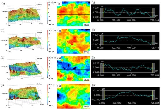
Figure 14.
Three-dimensional profile of Mg cross-section: (a–c) front waist; (d–f) peak; (g–i) back waist; (j–l) trough.
Table 4.
Roughness statistics of Mg matrix fracture surfaces.
Figure 15 is the schematic diagram of Mg/Al interface bonding during the corrugated rolling process. The interface bonding process can be divided into four stages: (1) Extrusion deformation occurred. After wire brush grinding, the surfaces to be bonded of the Mg sheet and the Al sheet were rough and uneven, and a hardening layer was observed on the surfaces. In Region 1(R1), the Mg sheet was in contact with the upper corrugated roll, and the Al sheet was in contact with the lower flat roll. At this time, the interface metal was almost undeformed, and the surface hardening layer was subjected to small forces and was not deformed. When the Mg and Al sheets entered Region 2 (R2), the metal stretching during the corrugated rolling process led to the tensile stress in the hardening layer in the stretching direction. The hardening layer was deformed by the extrusion of interfacial metals, which was accompanied by the generation of friction heat and deformation heat. (2) Next, rubbing fracture occurred. As the rolling process progressed, reductions increased gradually in Regions 3, 4 and 5 (R3, R4 and R5), and the compressive stress on the interfacial metal also increased gradually. The hardening layer broke due to strong rubbing action, exposing a large amount of fresh metals at the interface. (3) Then, compound extension occurred. In Regions 6 and 7 (R6 and R7), the fresh metals exposed at the interface were extruded through the cracks between the hardening layers, and extruded into each other’s matrix to form bonds under the action of the rolling force. Meanwhile, the shear deformation between the interface metals prompted grain refinement of the matrixes, thereby enhancing the interface bonding. Compound extensions formed at the interface, and the interface bonding effect enhanced. (4) The last stage was compound completion. Stable interface bonding was achieved in Region 8 (R8) until the rolled piece left the roll. Heat flow between the metals accompanied the entire rolling process.
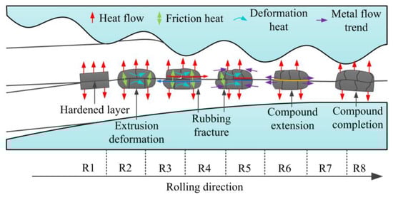
Figure 15.
Schematic diagram of interface bonding during the corrugated rolling process [28].
4. Conclusions
- After the corrugated rolling process, the interface of the corrugated Mg/Al clad sheet became well combined, and the interfacial metal grains refined significantly due to the strong plastic deformation. The transverse tensile results showed that the maximum UTS of the clad sheet at the trough position was ~296 MPa, while the minimum UTS at the peak position was ~257 MPa. On the contrary, the fracture EL was largest at the peak position (~13.4%), and smallest at the trough position (~10.6%).
- During the transverse tensile process, stress concentration occurred first in the Mg sheet, resulting in uneven stress distribution for both matrixes. As a result, the interface stratified first, then the Mg sheet broke, and finally the clad sheet failed along with the Al sheet fracturing.
- By analyzing the GND density of the matrixes, the strengthening mechanism of the peak position was determined to be mainly dislocation strengthening, while the strengthening mechanism of the trough position was mainly grain boundary strengthening.
- The interface bonding process of corrugated Mg/Al clad sheet can be divided into four stages: extrusion deformation, rubbing fracture, compound extension and compound completion.
Author Contributions
Writing—original draft, S.Z.; formal analysis, S.L.; writing—review and editing, Y.H.; conceptualization, T.W. All authors have read and agreed to the published version of the manuscript.
Funding
This study is financially supported by the National Key R&D Program of China (2018YFA0707300); the National Natural Science Foundation of China (51904205, 52204396); Central Government Guides the Special Fund Projects of Local Scientific and Technological Development (YDZJSX2021A020, YDZX20191400002149).
Institutional Review Board Statement
Not applicable.
Informed Consent Statement
Not applicable.
Data Availability Statement
Not applicable.
Conflicts of Interest
The authors declare no conflict of interest.
References
- Wasekar, N.P.; Latha, S.M.; Ramakrishna, M.; Rao, D.S.; Sundararajan, G. Pulsed electrodeposition and mechanical properties of Ni-W/SiC nano-composite coatings. Mater. Des. 2016, 112, 140–150. [Google Scholar] [CrossRef]
- Chen, L.; Fu, Y.; Yin, F.; Liu, N.; Liang, C. Microstructure and Mechanical Properties of Mg/Al Clad Bars with Ni Interlayer Processed by Compound Castings and Multi-Pass Caliber Rolling. Metals 2018, 8, 704. [Google Scholar] [CrossRef]
- Ahledel, N.; Schulz, R.; Gariepy, M.; Hermawan, H.; Alamdari, H. Electrochemical Corrosion Behavior of Fe3Al/TiC and Fe3Al-Cr/TiC Coatings Prepared by HVOF in NaCl Solution. Metals 2019, 9, 437. [Google Scholar] [CrossRef]
- Wachowski, M.; Kosturek, R.; Sniezek, L.; Mroz, S.; Stefanik, A.; Szota, P. The Effect of Post-Weld Hot-Rolling on the Properties of Explosively Welded Mg/Al/Ti Multilayer Composite. Materials 2020, 13, 1930. [Google Scholar] [CrossRef]
- Nie, H.H.; Liang, W.; Chen, H.S.; Zheng, L.W.; Chi, C.Z.; Li, X.R. Effect of annealing on the microstructures and mechanical properties of Al/Mg/Al laminates. Mater. Sci. Eng. A. 2018, 732, 6–13. [Google Scholar] [CrossRef]
- Zhang, N.; Wang, W.X.; Cao, X.Q.; Wu, J.Q. The effect of annealing on the interface microstructure and mechanical characteristics of AZ31B/AA6061 composite plates fabricated by explosive welding. Mater. Des. 2015, 65, 1100–1109. [Google Scholar] [CrossRef]
- Qi, Z.C.; Yu, C.; Xiao, H. Microstructure and bonding properties of magnesium alloy AZ31/CP-Ti clad plates fabricated by rolling bonding. J. Manuf. Process. 2018, 32, 175–186. [Google Scholar] [CrossRef]
- Nemcko, M.J.; Qiao, H.; Wu, P.D.; Wilkinson, D.S. Effects of void fraction on void growth and linkage in commercially pure magnesium. Acta. Mater. 2016, 113, 68–80. [Google Scholar] [CrossRef]
- Yang, M.; Liu, X.B.; Zhang, Z.Y.; Song, Y.L. Stress Corrosion Behavior of AM50Gd Magnesium Alloy in Different Environments. Metals 2019, 9, 616. [Google Scholar] [CrossRef]
- Feng, G.; Watari, H.; Haga, T. Fabrication of Mg/Al Clad Strips by Direct Cladding from Molten Metals. Metals 2022, 12, 1408. [Google Scholar] [CrossRef]
- Wang, Y.; Liao, Y.; Wu, R.; Turakhodjaev, N.; Chen, H.; Zhang, J.; Zhang, M.; Mardonakulov, S. Microstructure and mechanical properties of ultra-lightweight Mg-Li-Al_Al-Li composite produced by accumulative roll bonding at ambient temperature. Mater. Sci. Eng. A. 2020, 787, 139494. [Google Scholar] [CrossRef]
- Nie, H.; Liang, W.; Chen, H.; Wang, F.; Li, T.; Chi, C.; Li, X.r. A coupled EBSD/TEM study on the interfacial structure of Al/Mg/Al laminates. J. Alloy. Compd. 2019, 781, 696–701. [Google Scholar] [CrossRef]
- Nie, H.; Liang, W.; Zheng, L.; Ren, X.; Chi, C.; Fan, H. The Microstructure, Texture and Mechanical Properties of the Rolled Al/Mg/Al Clad Sheets. J Mater. Eng. Perform. 2016, 25, 4695–4705. [Google Scholar] [CrossRef]
- Chang, H.; Zheng, M.Y.; Xu, C.; Fan, G.D.; Brokmeier, H.G.; Wu, K. Microstructure and mechanical properties of the Mg/Al multilayer fabricated by accumulative roll bonding (ARB) at ambient temperature. Mater. Sci. Eng. A. 2012, 543, 249–256. [Google Scholar] [CrossRef]
- Chang, H.; Zheng, M.Y.; Gan, W.M.; Wu, K.; Maawad, E.; Brokmeier, H.G. Texture evolution of the Mg/Al laminated composite fabricated by the accumulative roll bonding. Scripta. Mater. 2009, 61, 717–720. [Google Scholar] [CrossRef]
- Thangapandian, N.; Balasivanandha Prabu, S.; Padmanabhan, K.A. Effects of die profile on grain refinement in Al–Mg alloy processed by repetitive corrugation and straightening. Mater. Sci. Eng. A 2016, 649, 229–238. [Google Scholar] [CrossRef]
- Bhovi, P.M.; Patil, D.C.; Kori, S.A.; Venkateswarlu, K.; Huang, Y.; Langdon, T.G. A comparison of repetitive corrugation and straightening and high-pressure torsion using an Al-Mg-Sc alloy. J. Mater. Res. Technol. 2016, 5, 353–359. [Google Scholar] [CrossRef]
- Wang, T.; Li, S.; Ren, Z.; Han, J.; Huang, Q. A novel approach for preparing Cu/Al laminated composite based on corrugated roll. Mater. Lett. 2019, 234, 79–82. [Google Scholar] [CrossRef]
- Wang, T.; Wang, Y.; Bian, L.; Huang, Q. Microstructural evolution and mechanical behavior of Mg/Al laminated composite sheet by novel corrugated rolling and flat rolling. Mater. Sci. Eng. A 2019, 765, 138318. [Google Scholar] [CrossRef]
- Tang, J.W.; Chen, L.; Zhao, G.Q.; Zhang, C.S.; Yu, J.Q. Study on Al/Mg/Al sheet fabricated by combination of porthole die co-extrusion and subsequent hot rolling. J. Alloy. Compd. 2019, 784, 727–738. [Google Scholar] [CrossRef]
- Tang, J.; Chen, L.; Zhao, G.; Zhang, C.; Sun, L. Achieving three-layered Al/Mg/Al sheet via combining porthole die co-extrusion and hot forging. J. Magnes. Alloy. 2020, 8, 654–666. [Google Scholar] [CrossRef]
- Ateba Betanda, Y.; Helbert, A.-L.; Brisset, F.; Mathon, M.-H.; Waeckerlé, T.; Baudin, T. Measurement of stored energy in Fe–48%Ni alloys strongly cold-rolled using three approaches: Neutron diffraction, Dillamore and KAM approaches. Mater. Sci. Eng. A 2014, 614, 193–198. [Google Scholar] [CrossRef]
- Kubin, L.P.; Mortensen, A. Geometrically necessary dislocations and strain-gradient plasticity: A few critical issues. Scripta. Mater. 2003, 48, 119–125. [Google Scholar] [CrossRef]
- Gao, H.; Huang, Y.; Nix, W.D.; Hutchinson, J.W. Mechanism-based strain gradient plasticity-I. Theory. J. Mech. Phys. Solids. 1999, 47, 1239–1263. [Google Scholar] [CrossRef]
- Wan, Y.; Tang, B.; Gao, Y.; Tang, L.; Sha, G.; Zhang, B.; Liang, N.; Liu, C.; Jiang, S.; Chen, Z.; et al. Bulk nanocrystalline high-strength magnesium alloys prepared via rotary swaging. Aata. Mater. 2020, 200, 274–286. [Google Scholar] [CrossRef]
- Kalsar, R.; Yadav, D.; Sharma, A.; Brokmeier, H.G.; May, J.; Höppel, H.W.; Skrotzki, W.; Suwas, S. Effect of Mg content on microstructure, texture and strength of severely equal channel angular pressed aluminium-magnesium alloys. Mater. Sci. Eng. A 2020, 797, 140088. [Google Scholar] [CrossRef]
- Lee, J.H.; Lee, J.U.; Kim, S.-H.; Song, S.W.; Lee, C.S.; Park, S.H. Dynamic recrystallization behavior and microstructural evolution of Mg alloy AZ31 through high-speed rolling. J. Mater. Sci. Technol. 2018, 34, 1747–1755. [Google Scholar] [CrossRef]
- Wang, T.; Liu, W.; Liu, Y.; Wang, Z.; Ignatov, A.V.; Huang, Q. Formation mechanism of dynamic multi-neutral points and cross shear zones in corrugated rolling of Cu/Al laminated composite. J. Mater. Process. Tech. 2021, 295, 117157. [Google Scholar] [CrossRef]


Disclaimer/Publisher’s Note: The statements, opinions and data contained in all publications are solely those of the individual author(s) and contributor(s) and not of MDPI and/or the editor(s). MDPI and/or the editor(s) disclaim responsibility for any injury to people or property resulting from any ideas, methods, instructions or products referred to in the content. |
© 2023 by the authors. Licensee MDPI, Basel, Switzerland. This article is an open access article distributed under the terms and conditions of the Creative Commons Attribution (CC BY) license (https://creativecommons.org/licenses/by/4.0/).