Abstract
Arsenic–iron precipitate was treated using a carbon thermal magnetization reduction method in order to recover arsenic and iron. Arsenic–iron precipitate mixed with coke powder was roasted at a low temperature; arsenic was recovered in the form of As2O3, and iron was recovered in the form of Fe3O4. The volatilization rate of arsenic was 97.45%, and the content of arsenic in the precipitate was decreased to 0.60%. Iron and arsenic were recovered in the form of Fe3O4 and As2O3 with a purity of 99.91 wt.% under the conditions of a roasting temperature of 650 °C, coke powder addition of 25 wt.%, a roasting time of 180 min, and an argon flow rate of 10 L/min. The volatilization of arsenic was controlled by a chemical controlling step at 20–100 min, and this was switched to a diffusion controlling step at 120–180 min by kinetic experiments. The reaction mechanism of arsenic and iron under carbon thermal magnetization reduction was as follows: in the early stage of the reaction, a large amount of FeAsO4 was decomposed into As2O3 and Fe3O4; in the middle and late stages of the reaction, FeAsO4 was continuously decomposed and reduced, and the content of Fe3O4 was continuously increased until all iron was magnetized to generate Fe3O4, and the decomposed As2O3 volatilized into dust. Arsenic reacted with CaO to generate Ca3(AsO4)2, and this may be the reason why arsenic could not be removed completely.
1. Introduction
With the exhausting of mineral resources, complex arsenic-containing mineral resources are gradually being exploited and used. During the smelting process, a proportion of arsenic enters into the smelting wastewater, forming arsenic-containing wastewater, which must be treated up to the standard and recycled. The iron precipitation method is one of the main methods to treat arsenic-containing wastewater. This method involves adding ferric salt into arsenic-containing wastewater to generate the iron salt precipitation of arsenic, namely, arsenic–iron precipitate, so as to achieve the purpose of arsenic removal [1,2,3,4,5,6].
Arsenic–iron precipitate is a hazardous waste substance that must be treated to render it harmless to the environment. At present, the treatment methods of arsenic–iron precipitate are mainly solidification, including polymer solidification, glass solidification, and cement solidification [7,8,9,10]. The polymer solidification method is based on polymer compounds, such as asphalt, polyethylene, polyester resin, etc., which solidify arsenic in organic polymer compounds to block the dissolution of arsenic [10,11,12]. This method has high solidification efficiency and a low arsenic dissolution rate; however, the polymer solidification method has the disadvantages of easy aging to a solidified body and high cost, and it is still in the theoretical research stage. The glass solidification method is mainly a solid waste solution that mixes arsenic–iron precipitate with the components of relevant glass and then seals the arsenic-containing waste precipitate in the glass body after high temperature melting at 850–1300 °C and cooling to room temperature [13,14,15]. When arsenic–iron precipitate is treated with the glass matrix, the waste precipitate particles will be coated by the surrounding vitrified components, thus forming a compact protective film to prevent the arsenic element from leaching out. The treatment must go through a high-temperature melting process. As the arsenic-containing compounds are volatile, the glass solidification method is mainly used in the treatment of low-volatility or non-volatile arsenic-containing industrial waste residue. This method has the disadvantages of a complicated preparation process and a high running cost, and it is difficult to apply on an industrial scale. The cement solidification method uses the gel formed by cement hydration to wrap arsenic–iron precipitate, so as to achieve the purpose of inhibiting arsenic leaching [16,17]. This method is simple in terms of the process, is low in terms of equipment and operating costs, and is the main method for the solidification treatment of arsenic–iron precipitate. The disadvantages of the cement solidification method are that arsenic–iron cannot be utilized as a resource; the volume after solidifying is increased by 3–5 times, and the solidification of arsenic–iron precipitate must be stored in a precipitate yard, which increases the running cost of the precipitate yard and shortens the service life of the precipitate yard. Therefore, the solidification method is not the best way of treating arsenic–iron precipitate.
Arsenic–iron precipitate contains 20–35 wt.% iron and 30–40 wt.% arsenic. It is not only a hazardous waste substance but is also an important iron resource that needs to be comprehensively utilized. The methods of resource utilization of arsenic-containing precipitate are mainly the pyrometallurgical method, hydrometallurgy method, and pyrometallurgical–hydrometallurgy combined method [18,19,20,21,22,23,24,25,26]. The pyrometallurgical method is based on the volatile characteristics of arsenic trioxide, which volatilizes arsenic in the form of As2O3 to recycle arsenic, and the arsenic-removed precipitate is returned to the smelting process to recycle valuable metals [27,28]. This method is mainly based on the difference in the saturated vapor pressure between different elements and arsenic to realize the separation of arsenic. It is suitable for the separation of non-volatile elements and arsenic. This method is not applicable to systems containing many volatile elements. The hydrometallurgy method is based on the characteristic that arsenic is easily soluble in acid and alkali. Consequently, acid or alkali is used to leach arsenic into the leaching solution, and valuable metals in the arsenic-removed precipitate are recycled by wet leaching [29,30,31,32]. This method can realize the effective separation of arsenic and other valuable metals, and the effective recovery and utilization of valuable metals can be realized by a multi-step leaching method. The disadvantage of this method is that arsenic is removed in the form of slag, forming new arsenic-containing hazardous waste, which is difficult to use. In addition, arsenic-containing wastewater will also be produced, which requires treatment to render it harmless. The pyrometallurgical–hydrometallurgy combined method recovers arsenic via the pyrometallurgical method and recovers valuable metals via the hydrometallurgy method [33,34]. This method uses the pyrometallurgy method to recycle arsenic in the form of arsenic trioxide or arsenic product and then uses the wet leaching method to recover valuable metals from the arsenic-removed slag, effectively avoiding the generation of secondary arsenic-containing waste slag and arsenic-containing wastewater. The disadvantages of this method are the long and complex process required and the large equipment investment.
Arsenic in arsenic–iron precipitate mainly exists in the form of ferric arsenate. Determining how to efficiently remove arsenic from arsenic–iron precipitate and recover iron from the precipitate is the key difficulty associated with the resource utilization of arsenic–iron precipitate. Based on the characteristics of As2O3 making it volatile and iron being magnetic, this paper used the carbon thermal magnetization reduction method to reduce the iron in arsenic–iron precipitate using ferroferric oxide and to reduce the arsenic by using arsenic trioxide. In this paper, the effects of the roasting temperature, coke powder addition, and roasting time on the experimental results were investigated, and the kinetics of arsenic volatilization during carbon thermal magnetization reduction in arsenic–iron precipitate was systematically studied. The reaction mechanism of arsenic and iron in carbon thermal magnetization reduction was studied. This method realized the resource utilization of arsenic and iron in arsenic–iron precipitate, and it provides a new idea for treating arsenic–iron precipitate.
2. Experimental Section
2.1. Materials
Arsenic–iron precipitate was collected from a copper smelting factory in Southwest China, which was produced in the treatment process of arsenic-containing wastewater. As it contained a lot of water, the factory used the method of filter pressing and dried the precipitate. The raw material of this experiment was the roasted and dried arsenic–iron precipitate of this factory. The reductant was coke powder, with a carbon content of 75.51%, ash content of 18.48%, and volatile content of 6.01%, which was milled to a particle size of ≤0.15 mm; and the particle sizes were as follows: 0.075–0.15 mm of 87.53 wt.% and 0.00874–0.075 mm of 12.47 wt.%. The purity of the commercial argon was 99.999%. The chemical composition analysis of the arsenic–iron precipitate is shown in Table 1, and the X-ray diffraction analysis is shown in Figure 1. The mineral composition distribution of the arsenic–iron precipitate was determined by electron probe microanalysis (EPMA), as presented in Figure 2. It can be seen from Figure 1 that the main components of the arsenic–iron precipitate were FeAsO4 and CaO. Moreover, it can be seen from Figure 2 that the mineral phase distribution of arsenic and iron in the arsenic–iron precipitate was mainly FeAsO4, consisting of a small amount of free As2O3 and a small amount of CaO.

Table 1.
Chemical composition analysis of the arsenic–iron precipitate/wt.%.
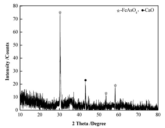
Figure 1.
XRD patterns of the arsenic–iron precipitate.
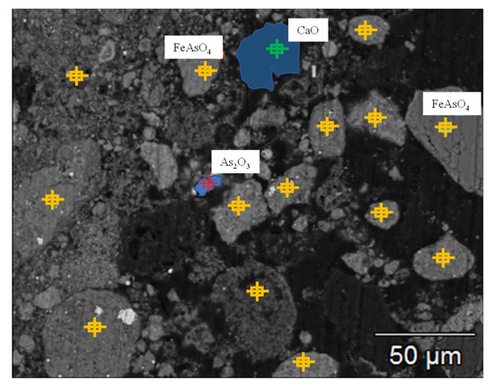
Figure 2.
Mineral phase distribution of the arsenic–iron precipitate analyzed by EPMA.
2.2. Experimental Device and Methods
Experimental device: The experimental device was a vertical tubular atmosphere furnace, as shown in Figure 3, with a size of Φ20 mm × 150 mm. A silicon carbide rod was used for heating; the highest heating temperature was 1000 °C, and the temperature control accuracy was ±2 °C. In the kinetic experiments, a quartz crucible was hung on the analytical balance.
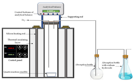
Figure 3.
Experimental device.
Experimental method: The arsenic–iron precipitate and coke powder were mixed in proportion, put into a quartz crucible, and reacted at a certain temperature under an introduced argon atmosphere. The dust was collected by the absorption bottle, and the tail gas was absorbed by alkali liquor. The volatilization rate of arsenic was calculated by Equation (1).
xi = (m0 × x0 − m1 × x1) × 100%/m0 × x0
In Equation (1): xi wis the volatilization rate of arsenic, wt.%; m0 is the weight of added arsenic iron precipitate, kg; x0 is the arsenic content in the arsenic iron precipitate, wt.%; m1 is the weight of the arsenic–iron precipitate after reaction, kg; x1 is the content of arsenic in the precipitate after reaction, wt.%.
2.3. Analysis and Detection Methods
An X-ray diffraction analyzer was used for phase analysis (model D/max-3B, manufactured by Nishiko Corporation in Osaka City of Japan), with a scanning range of 5–80° and a step length of 8°/min. An electron probe analyzer was used for the mineral phase distribution of the arsenic–iron precipitate (EPMA-8050G, manufactured by Shimadzu Company in Kyoto City of Japan). When the arsenic content was ≥1%, an EDTA volumetric method was used for determination; when the arsenic content was <1%, ICP-AES was used for determination. Other elements were determined by ICP-AES.
2.4. Thermodynamic Analysis
The possible chemical reactions of carbon thermal magnetization reduction in the standard-state of the arsenic–iron precipitate are shown in Equations (2)–(6).
3FeAsO4 + 7/2CO(g) = Fe3O4 + 7/2CO2(g) + 3/2As2O3
2FeAsO4 + 2CO(g) = Fe2O3 + 2CO2(g) + As2O3
2FeAsO4 + 3CO(g) = 2FeO + 3CO2(g) + As2O3
2FeAsO4 + 5CO(g) = 2Fe + 5CO2(g) + As2O3
3CaO + 8/3As2O3 + 3CO(g) = Ca3(AsO4)2 + 10/3As + 3CO2(g)
HSC software (version 6.5 provided by Thermo-Calc Software Company in Stockholm City of Sweden) was used to calculate the ΔGθ of Equations (2)–(6) at 300–700 °C and to draw the ΔGθ − T diagram of Equations (2)–(6) at 300–700 °C, as shown in Figure 4.
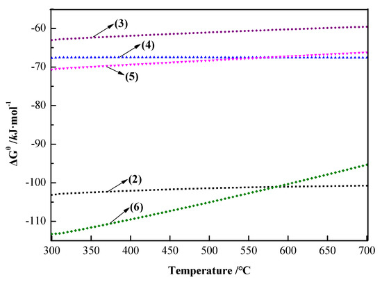
Figure 4.
ΔGθ−T diagram of Equations (2)–(6) at 300–700 °C.
The phase of arsenic and iron in the arsenic precipitate was mainly FeAsO4. The following can be seen from Figure 3: (1) FeAsO4 was reduced to Fe2O3, Fe3O4, FeO, and Fe by carbon. At 300–700 °C, FeAsO4 was most likely reduced to Fe3O4 by carbon. (2) During the carbon thermal magnetization reduction process, the arsenic in FeAsO4 would finally exist in the form of As2O3. (3) Fe3O4 is magnetic and could be recovered from roasting the precipitate by magnetic separation, and As2O3 could be volatilized into dust for recovery. (4) Ca3(AsO4)2 [35,36,37] would be generated by Equation (6), which would hinder the volatilization of arsenic. Due to the low content of CaO in the raw materials, this reaction would not seriously affect the volatilization of arsenic; however, it also indicated that arsenic could not be removed completely due to the generation of Ca3(AsO4)2. Therefore, the method of carbon thermal magnetization reduction can be adopted to recover iron from arsenic–iron precipitate with Fe3O4 and arsenic with As2O3 so as to realize the resource utilization of iron and arsenic in arsenic–iron precipitate.
3. Experimental Results and Discussion
3.1. Influence of Temperature on the Experimental Results
Experimental conditions: coke powder addition was 25 wt.%, the roasting time was 180 min, and the argon flow rate was 10 L/min. The influence of temperature on the experimental results was investigated. The arsenic volatilization rates and arsenic content in the precipitate roasted at different temperatures are shown in Figure 5. The precipitate roasted at different temperatures was analyzed by X-ray diffraction, and the results are shown in Figure 6.
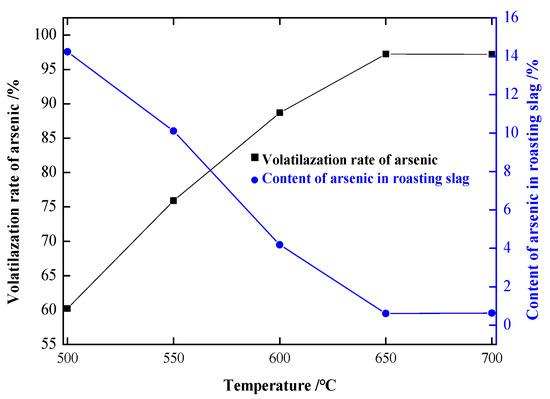
Figure 5.
Influence of temperature on the experimental results.
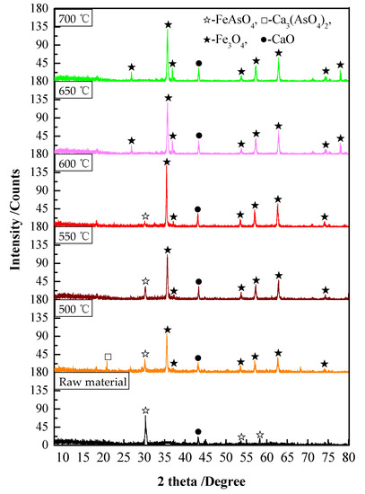
Figure 6.
XRD patterns of the precipitate roasted at different temperatures.
As shown in Figure 5, the volatilization rate of arsenic increased with the increase in temperature. At 500 °C, the volatilization rate of arsenic was 60.31%, and the content of arsenic in the precipitate was 14.19%. At 600 °C, the volatilization rate of arsenic was increased to 97.45%, and the content of arsenic in the precipitate was decreased to 0.60%. After that, the volatilization rate of arsenic remained basically unchanged when the temperature continued to rise; therefore, 650 °C was determined to be the best experimental temperature for arsenic volatilization.
The following can be seen from Figure 6: (1) With the increase in the reaction temperature, FeAsO4 was gradually decomposed, and iron in the arsenic–iron precipitate was mainly magnetized to Fe3O4 according to Equation (2). (2) At 650 °C, there was no peak in FeAsO4 in the XRD pattern, FeAsO4 was completely decomposed, and the generated As2O3 volatilized into dust and was separated from the precipitate. (3) At 500 °C, the peak of Ca3(AsO4)2 could be clearly observed, which indicated that CaO would hinder the volatilization of arsenic according to Equation (6). (4) With the increase in temperature, the content of Ca3(AsO4)2 gradually decreased, and the peak of Ca3(AsO4)2 could hardly be observed at 650 °C. This may be because the volatilization rate of As2O3 increased rapidly with the increase in temperature, which led to As2O3 being unable to fully react with CaO, thus reducing the generation of Ca3(AsO4)2. Moreover, because the content of CaO in the raw material was very small, the generated amount of Ca3(AsO4)2 was very small. Therefore, in order to decompose FeAsO4 and avoid the formation of Ca3(AsO4)2 as much as possible, the optimal experimental temperature was 650 °C. At this temperature, the volatilization rate of arsenic in the arsenic–iron precipitate was 97.36% and the content of arsenic in the precipitate was 0.60%. Iron was basically magnetized to Fe3O4.
3.2. Influence of Coke Powder Addition on the Experimental Results
Experimental conditions: the roasting temperature was 650 °C, the roasting time was 180 min, and the argon flow rate was 10 L/min. The influence of coke powder addition on the experimental results was investigated. The arsenic volatilization rates and arsenic contents in the precipitate roasted at different coke powder additions are shown in Figure 7. The precipitate roasted at different coke powder additions was analyzed by X- ray diffraction, and the results are shown in Figure 8.
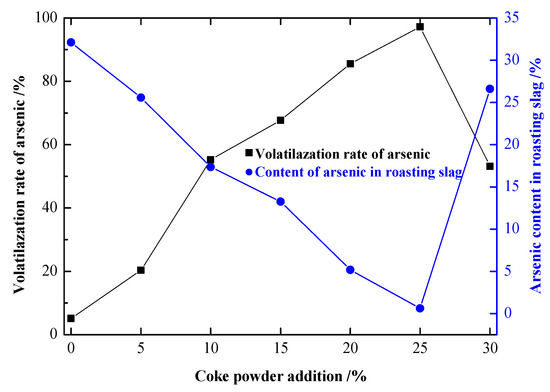
Figure 7.
Influence of coke powder addition on the experimental results.
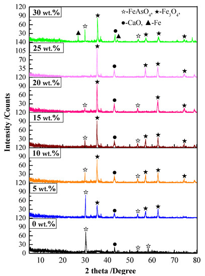
Figure 8.
XRD patterns of the precipitate roasted under different coke powder additions.
As shown in Figure 7, when 0 wt.% coke powder was added, the volatilization rate of arsenic was 5.28%, which was the direct volatilization of a small amount of free As2O3 in the arsenic–iron precipitate. With the increase in coke powder addition, the volatilization rate of arsenic increased rapidly. When the coke powder addition was 10 wt.%, the volatilization rate of arsenic was 55.45%. When the coke powder addition was 25 wt.%, the volatilization rate of arsenic was 97.45%, and the arsenic content in the precipitate decreased to 0.60%. With the addition of 30 wt.% coke powder, the volatilization rate of arsenic decreased significantly to only 53.16%. As can be seen from Figure 8, with the addition of 30 wt.% coke powder, FeAsO4 was excessively reduced to Fe due to the excessive reduction atmosphere, and the roasted precipitate partially melted, which greatly reduced the volatilization rate of arsenic.
The following can be seen from Figure 8: (1) With the increase in carbon addition, FeAsO4 was gradually decomposed. In addition, iron in the arsenic–iron precipitate was magnetized to Fe3O4 mainly according to Equation (2). (2) When 25 wt.% coke powder was added, the peak of FeAsO4 could hardly be detected in the XRD patterns, FeAsO4 was completely decomposed, and the generated As2O3 was volatilized into dust and was separated from the precipitate. (3) When 30 wt.% coke powder was added, the peak of Fe could clearly be observed in the XRD patterns. An excessive reducing atmosphere made part of FeAsO4 generate Fe according to Equation (5). Furthermore, the burning of a large amount of coke powder caused overheating, resulting in partial melting of the roasted precipitate, which greatly reduced the volatilization rate of arsenic. From the experiments, it was determined that 25 wt.% coke powder addition was the optimal experimental condition.
3.3. Influence of the Roasting Time on the Experimental Results
Experimental conditions: the roasting temperature was 650 °C, the coke powder addition was 25 wt.%, and the argon flow rate was 10 L/min. The influence of the roasting time on the experimental results was investigated. The arsenic volatilization rates and arsenic contents in the precipitate roasted at different roasting times are shown in Figure 9.
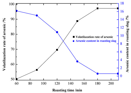
Figure 9.
Influence of the roasting time on the experimental results.
It can be seen from Figure 9 that the volatilization rate of arsenic was significantly increased by prolonging the roasting time. At 60 min, the volatilization rate of arsenic was 50.27%, and the arsenic content in the precipitate was 16.20%. At 180 min, the volatilization rate of arsenic was 97.45%, and the content of arsenic in the precipitate was 0.60%. After that, the volatilization rate of arsenic remained stable when the time was prolonged. Therefore, 180 min was the optimal roasting time.
3.4. Kinetic Analysis of the Arsenic Volatilization Process
The shrinking core model (SCM) [37,38,39,40] was used to study the kinetic volatilization process of arsenic in the carbon thermal magnetization process. The volatilization rates of arsenic under different temperatures and roasting times with coke powder of 25 wt.% are shown in Figure 10. The kinetic equations with different controlling steps of the SCM are shown in Table 2. In Table 2, kd, kr, and km are the apparent rate constants (min−1) that were controlled by a diffusion controlling step, a chemical reaction controlling step, and a hybrid controlling step.
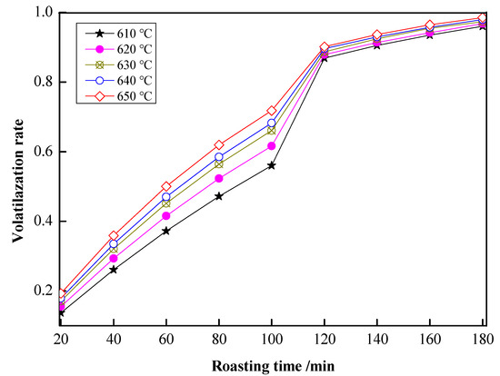
Figure 10.
Volatilization rates of arsenic under different roasting temperatures and roasting times.
Table 2.
Kinetic equations of the SCM.
With roasting time as the x-axis and 1 − (1 − x)1/3 as the y-axis, the relationship between roasting time and 1 − (1 − x)1/3 is shown in Figure 11. As shown in Figure 11, there was a good fit between the roasting time and 1 − (1 − x)1/3 at 20–100 min under 610–650 °C. In Figure 11, the slope of the fitting line was ki; with 1000/T as the x-axis and –lnki as the y-axis, the relationship between 1000/T and –lnkr is shown in Figure 12. In Figure 12, fitting the points, a straight line with a slope value of 7.12563 was observed. Therefore, the value of Ea was 59.24 kJ/mol, and the controlling step in the volatilization was the chemical controlling step.
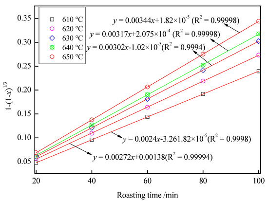
Figure 11.
The relationship between the roasting time and 1 − (1 − x)1/3.
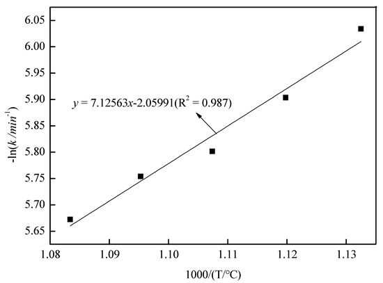
Figure 12.
The relationship between 1000/(T/°C) and −lnkr.
With the roasting time as the x-axis and 1 − 2/3x − (1 − x)2/3 as the y-axis, the relationship between the roasting time and 1 − 2/3x − (1 − x)2/3 is shown in Figure 13. As shown in Figure 13, there was a good fit between the roasting time and 1 − 2/3x − (1 − x)2/3 at 120–180 min at 610–650 °C. In Figure 13, the slope of the fitting line was kd. With 1000/T as the x-axis and –lnki as the y-axis, the relationship between 1000/T and –lnkd is shown in Figure 14. In Figure 14, fitting the points, a straight line with a slope value of 2.509 was observed. Therefore, the value of Ea was 20.89 kJ/mol, and the controlling step in the volatilization was the diffusion controlling step.
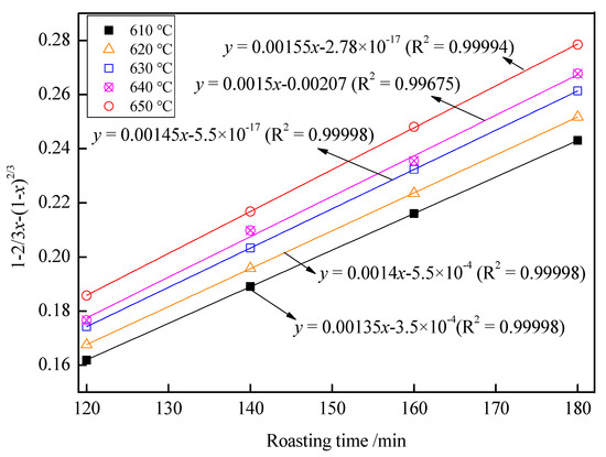
Figure 13.
The relationship between the roasting time and 1 − 2/3x − (1 − x)2/3.
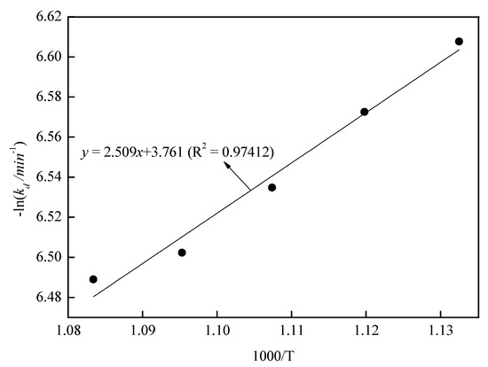
Figure 14.
The relationship between 1000/(T/°C) and −lnkd.
3.5. Mechanism Analysis of Arsenic Volatilization and Iron Magnetization
The mineral composition distribution of the roasted precipitate was determined by EMPA. The EPMA photos of the precipitate roasted at different times are presented in Figure 15. According to the previous experiments above and the EPMA photos, the following was observed: (1) During the early stage of the reaction, a large amount of FeAsO4 was decomposed into As2O3 and Fe3O4. At 60 min, As2O3 was obviously detected in the roasted precipitate. As2O3 was volatilized into dust, and at the same time, Fe3O4 was generated. (2) In the middle and late stages of the reaction, FeAsO4 was continuously decomposed and reduced, and the content of Fe3O4 was continuously increased until all iron was magnetized to generate Fe3O4, and the decomposed As2O3 volatilized into the dust. After 100 min, As2O3 could no longer be detected in the precipitate. This is because As2O3 was volatilized immediately when it was formed due to the volatile property of As2O3. (3) A small amount of arsenic reacted with CaO to generate Ca3(AsO4)2. As time extended, the arsenic content in CaO increased significantly, and the generation of Ca3(AsO4)2 may be the reason why the arsenic content in the final product was still 0.60%.
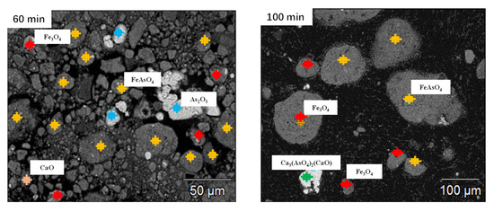
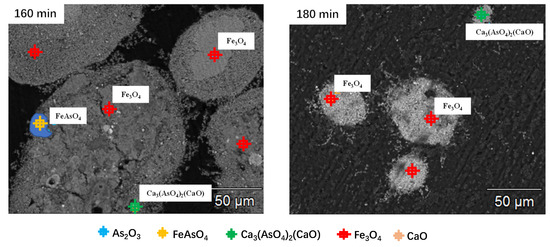
Figure 15.
EPMA photos of the precipitate roasted at different roasting times.
Before 20 min, a small amount of arsenic volatilized, mainly due to the volatilization of free As2O3 in the arsenic–iron precipitate. After that, FeAsO4 in the arsenic–iron precipitate began to decompose in large amounts. A large amount of As2O3 was released and volatilized to dust, and a large amount of iron trioxide was generated. This process occurred at 20–100 min, and the key controlling step was the chemical controlling step. At 120–180 min, with the continuous reduction of FeAsO4, the decomposition rate of residual FeAsO4 became slower. As2O3 was slowly generated and volatilized into dust, and a small amount of iron trioxide was produced until arsenic was volatilized completely. This process occurred at 120–180 min, and the key controlling step was the diffusion controlling step. Arsenic remained in the roasted precipitate, with 0.60% wt.% being due to the generation of Ca3(AsO4)2. The reaction mechanism of arsenic and iron in the carbon thermal magnetization reduction is shown in Figure 16.
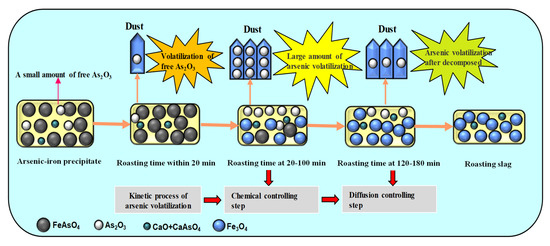
Figure 16.
The reaction mechanism of arsenic and iron in carbon thermal magnetization reduction.
3.6. Products
The chemical composition analyses of the roasted precipitate and dust are shown in Table 3, and the X-ray diffraction analyses of the roasted precipitate and dust are shown in Figure 17 and Figure 18.
Table 3.
Chemical composition analysis of arsenic–iron precipitate /wt.%.
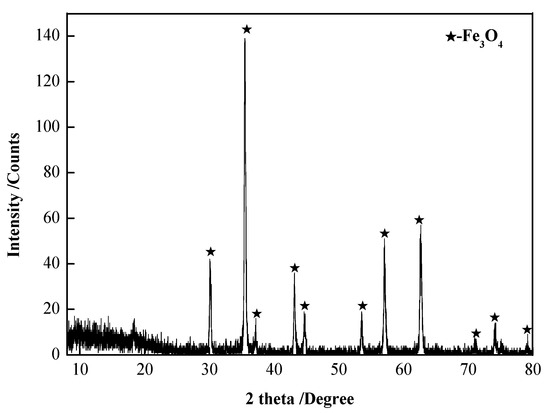
Figure 17.
XRD patterns of the roasted precipitate.
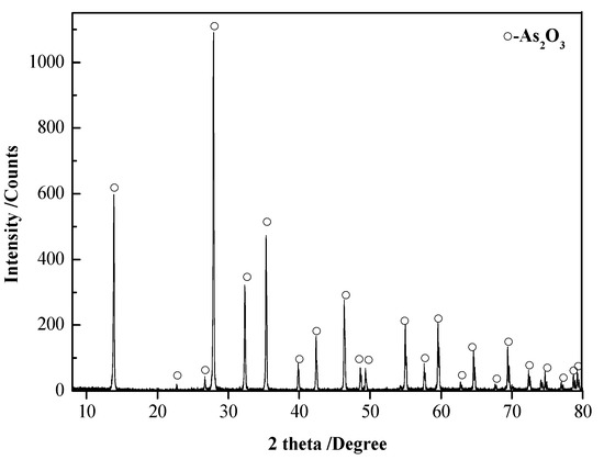
Figure 18.
XRD patterns of the dust.
The following can be seen from Figure 17 and Figure 18 and Table 3: (1) The roasted precipitate was mainly Fe3O4, containing arsenic at 0.60 wt.% and a very small amount of Ca, Si, and Cu. Iron was separated from other impurities by magnetic separation and recovered in the form of Fe3O4. (2) The dust was mainly As2O3, and the purity of As2O3 was 99.91 wt.%, which can be used as the raw material for smelting arsenic.
4. Conclusions
- (1)
- Arsenic and iron in iron–arsenic precipitate can be recovered via the carbon thermal magnetization reduction method. Iron and arsenic were recovered in the form of Fe3O4 and As2O3 with a purity of 99.91 wt.%. The volatilization rate of arsenic was 97.45%. The content of arsenic in the precipitate was decreased to 0.60% under the conditions of a roasting temperature of 650 °C, coke powder addition of 25 wt.%, a roasting time of 180 min, and an argon flow rate of 10 L/min.
- (2)
- It was shown via kinetic experiments that the volatilization of arsenic was controlled by the chemical controlling step at 20–100 min, which switched to the diffusion controlling step at 120–180 min.
- (3)
- The reaction mechanism of arsenic and iron in carbon thermal magnetization reduction was as follows: During the early stage of the reaction, a large amount of FeAsO4 was decomposed into As2O3 and Fe3O4 and As2O3 was volatilized into dust. During the middle and late stages of the reaction, FeAsO4 was continuously decomposed and reduced, and the content of Fe3O4 was continuously increased until all iron was magnetized to generate Fe3O4, and the decomposed As2O3 volatilized into dust.
- (4)
- A small amount of arsenic reacted with CaO to generate Ca3(AsO4)2. This may be the reason why arsenic could not be removed completely. Future experimental studies are required to determine how to eliminate the generation of Ca3(AsO4)2 and realize the removal of arsenic completely.
Author Contributions
Conceptualization, D.L.; Writing—original draft, X.L.; Writing—review & editing, D.L.; Project administration, J.W., J.C. and Z.W. All authors have read and agreed to the published version of the manuscript.
Funding
This project was supported by the following funds: the Basic Research Plan of the Guizhou Provincial Department of Science and Technology [2020]1Y223, the Doctoral Talent Project of the Tongren Municipal Bureau of Science and Technology [2021]31, and the Doctoral Research Fund Project of Tongren University (200030405).
Institutional Review Board Statement
Not applicable.
Informed Consent Statement
Not applicable.
Data Availability Statement
No data are reported.
Acknowledgments
This project was supported by the following funds: the Basic Research Plan of the Guizhou Provincial Department of Science and Technology [2020]1Y223, the Doctoral Talent Project of the Tongren Municipal Bureau of Science and Technology [2021]31, and the Doctoral Research Fund Project of Tongren University (200030405). The authors wish to express their thanks to the organizations listed above for their financial support of this research.
Conflicts of Interest
The authors declare no conflict of interest.
References
- Nazari, A.M.; Radzinski, R.; Ghahreman, A. Review of arsenic metallurgy: Treatment of arsenical minerals and the immobilization of arsenic. Hydrometallurgy 2017, 174, 258–281. [Google Scholar] [CrossRef]
- Majzlan, J.; Drahota, P.; Filippi, M.; Grevel, K.; Kahl, W.; Plášil, j.; Boerio-Goates, J.; Woodfiedld, B.F. Thermodynamic properties of scorodite and parascorodite (FeAsO4·2H2O), kankite (FeAsO4·3.5H2O) and FeAsO4. Hydrometallurgy 2012, 117, 47–56. [Google Scholar] [CrossRef]
- Majzlan, J. Thermodynamic stabilization of hydrous ferric oxide by adsorption of phosphate and arsenate. Environ. Sci. Technol. 2011, 45, 4726–4732. [Google Scholar] [CrossRef] [PubMed]
- Gomez, M.A.; Assaaoudi, H.; Becze, L.; Cutler, J.N.; Demopoulos, G.P. Vibrational spectroscopy of hydrometallurgy produced (FeAsO4·2H2O), ferric arsenate sub-hydrate(FAsH: FeAsO4·0.75H2O) and basic ferric arsenate sulfate (BFAS:Fe[AsO4(1-x)(SO4)x(OH)x] ·wH2O). J. Raman. Spectrosc. 2010, 41, 212–221. [Google Scholar]
- Langmuir, D.; Mahoney, J.; Rowson, J. Solubility products of amorphous ferric arsenate and crystalline scorodite (FeAsO4·2H2O) and their application to arsenic behavior in buried mine tailings. Geochim. Cosmochim. Acta. 2006, 70, 2942–2956. [Google Scholar] [CrossRef]
- De Klerk, R.J.; Jia, Y.F.; Daenzer, R.; Gomez, M.A.; Demopoulos, G.P. Continuous circuit coprecipitation of arsenic (V) with ferric iron by lime neutralization: Process parameter effects on arsenic removal and precipitate quality. Hydrometallurgy 2012, 111, 65–72. [Google Scholar] [CrossRef]
- De Klerk, R.J.; Feldman, T.; Daenzer, R.; Demopoulos, G.P. Continuous circuit coprecipitation of arsenic (V) with ferric iron by lime neutralization: The effect of circuit staging, co-ions and equilibration pH on long-term arsenic retention. Hydrometallurgy 2015, 151, 42–45. [Google Scholar] [CrossRef]
- Zhao, Z.W.; Chai, L.Y.; Peng, B.; Liang, Y.Y.; He, Y.H.; Yan, Z.H. Arsenic vitrification by copper precipitate based glass: Mechanism and stability studies. J. Non-Cryst Solids 2017, 466–467, 21–28. [Google Scholar] [CrossRef]
- Xu, H.; Min, X.B.; Wang, Y.Y.; Ke, Y.; Yao, L.W.; Liu, D.G.; Chai, L.Y. Stabilization of arsenic sulfide sludge by hydrothermal treatment. Hydrometallurgy 2020, 191, 105–229. [Google Scholar] [CrossRef]
- Paktunc, D.; Bruggeman, K. Solubility of nanocrystalline scorodite and amorphous ferric arsenate: Implications for stabilization of arsenic in mine wastes. Appl. Geochem. 2010, 25, 674–683. [Google Scholar] [CrossRef]
- Ke, Y.; Chai, L.Y.; Min, X.B.; Tong, C.J.; Chen, J.; Wang, Y.; Liang, Y.J. Sulfidation of heavy-metal-containing neutralization sludge using zinc leaching residue as the sulfur source for metal recovery and stabilization. Miner. Eng. 2014, 61, 105–112. [Google Scholar] [CrossRef]
- Du, Y.; Xiao, H.X.; Lu, Q.; Du, D.Y. Using manganese precipitate to stabilize/solidify arsenic sulfide precipitate by moderate temperature calcination. Chin. J. Environ. Eng. 2017, 11, 1136–1140. (In Chinese) [Google Scholar]
- Chai, L.Y.; Yue, M.Q.; Li, Q.Z.; Zhang, G.S.; Zhang, M.X.; Wang, Q.W.; Liu, H.; Liu, Q.W. Enhanced stability of tooeleite by hydrothermal method for the fixation of arsenite. Hydrometallurgy 2018, 175, 93–101. [Google Scholar] [CrossRef]
- Viñals, J.; Sunyer, A.; Molera, P.; Cruells, M.; Llorca, N. Arsenic stabilization of calcium arsenate waste by hydrothermal precipitation of arsenical natroalunite. Hydrometallurgy 2010, 104, 247–259. [Google Scholar] [CrossRef]
- Ke, Y.; Chai, L.Y.; Min, X.B.; Tang, C.J.; Zhou, B.S.; Chen, J.; Yuan, C.Y. Behavior and effect of calcium during hydrothermal sulfidation and flotation of zinc-calcium-based neutralization sludge. Miner. Eng. 2015, 74, 68–78. [Google Scholar] [CrossRef]
- Chai, L.Y.; Ke, Y.; Min, X.B.; Min, X.B.; Zhou, B.S.; Xue, k.; Chen, j. Separation and recovery of ZnS from sulfidized neutralization sludge via the hydration conversion of CaSO4 into bulk CaSO4·2H2O crystals. Sep. Purif. Technol. Sep. Purif. Technol. 2015, 154, 76–81. [Google Scholar] [CrossRef]
- Liang, Y.J.; Min, X.B.; Chai, L.Y.; Wang, M.; Liyang, W.J.; Pan, Q.L.; Okido, M. Stabilization of arsenic sludge with mechanochemically modified zero valent iron. Chemosphere 2017, 168, 1142–1151. [Google Scholar] [CrossRef]
- Riveros, P.A.; Dutrizac, J.E.; Spencer, P. Arsenic disposal practices in the metallurgical industry. Can. Min. J. 2021, 40, 395–420. [Google Scholar] [CrossRef]
- Li, Y.K.; Zhu, X.; Qi, X.J.; Shu, B.; Zhang, X.; Li, K.Z.; Wei, Y.G.; Hao, F.Y.; Wang, H. Efficient removal of arsenic from copper smelting wastewater in form of scorodite using copper precipitate. J. Clean. Prod. 2020, 270, 1–12. [Google Scholar] [CrossRef]
- Bai, M.; Zheng, Y.J.; Liu, W.Y.; Zhang, C.F. Alkaline leaching and leaching kinetics of arsenic sulfide residue. J. Cent. South Univ. 2008, 39, 268–272. (In Chinese) [Google Scholar]
- Long, Y.; Yu, G.Y.; Dong, L.; Xu, Y.C.; Lin, H.J.; Deng, Y.; You, X.J.; Yang, L.N.; Liao, B.Q. Synergistic fouling behaviors and mechanisms of calcium ions and polyaluminum chloride associated with alginate solution in coagulation-ultrafiltration (UF) process. Water Res. 2021, 189, 116665–116676. [Google Scholar] [CrossRef] [PubMed]
- Yao, L.W.; Min, X.B.; Ke, Y.; Wang, Y.Y.; Liang, Y.J.; Yan, X.; Xu, H.; Fei, J.C.; Li, Y.C.; Liu, D.G.; et al. Release behaviors of arsenic and heavy metals from arsenic sulfide sludge during simulated storage. Minerals 2019, 9, 130–145. [Google Scholar] [CrossRef]
- Zhang, W.J.; Che, J.Y.; Wen, P.C.; Xia, L.; Ma, B.Z.; Chen, J.; Wang, C.Y. Co-treatment of copper smelting flue dust and arsenic sulfide residue by a pyrometallurgical approach for simultaneous removal and recovery of arsenic. J. Hazard. Mater. 2021, 416, 126149–126161. [Google Scholar] [CrossRef] [PubMed]
- Clancy, T.M.; Hayes, K.F.; Raskin, L. Arsenic waste management: A critical review of testing and disposal of arsenic-bearing solid wastes generated during arsenic removal from drinking water. Environ. Sci. Technol. 2013, 47, 10799–10812. [Google Scholar] [CrossRef] [PubMed]
- Lin, J.; Chen, N.; Pan, Y. Uptake mechanisms of arsenate in gypsum: Structural incorporation versus surface adsorption and implications for remediation of arsenic contamination. Geosci. Front. 2020, 27, 227–237. [Google Scholar]
- Zhang, W.F.; Lu, H.B.; Liu, F.; Wang, C.L.; Zhang, Z.H.; Zhang, J. Hydrothermal treatment of arsenic sulfide precipitate to immobilize arsenic into scorodite and recycle sulfur. J. Hazard. Mater. 2021, 406, 124735–124742. [Google Scholar] [CrossRef]
- Hu, H.J.; Qiu, K.Q. Three-step vacuum separation for treating arsenic sulphide residue. Vacuum. 2015, 111, 170–175. [Google Scholar] [CrossRef]
- Cheng, R.; Zhang, H.; Ni, H. Arsenic removal from arsenopyrite-bearing ore and arsenic recovery from ash by roasting method. Processe. 2019, 7, 754–765. [Google Scholar] [CrossRef]
- Yao, L.W.; Min, X.B.; Xu, H.; Ke, Y.; Liang, Y.J.; Yang, K. Hydrothermal treatment of arsenic sulfide residues from arsenic-bearing acid wastewater. Int. J. Environ. Res. Pub. Health 2018, 15, 1863. [Google Scholar] [CrossRef]
- Shahnazi, A.; Firoozi, S.; Fatmehsari, D.H. Selective leaching of arsenic from copper converter flue dust by Na2S and its stabilization with Fe2(SO4)3. T. Nonferr. Metal. Soc. 2020, 30, 1674–1686. [Google Scholar] [CrossRef]
- Gomez, M.A.; Becze, L.; Celikin, M.; Demopoulos, G.P. The effect of copper on theprecipitation of scorodite (FeAsO4.2H2O) under hydrothermal conditions: Evidencefor a hydrated copper containing ferric arsenate sulfate-short lived intermediate. J. Colloid Interface Sci. 2011, 360, 508–518. [Google Scholar] [CrossRef] [PubMed]
- Liu, D.G.; Min, X.B.; Ke, Y.; Chai, L.Y.; Liang, Y.J.; Li, Y.C.; Yao, L.W.; Wang, Z.B. Co-treatment of flotation waste, neutralization sludge, and arsenic-containing gypsum sludge from copper smelting: Solidification/stabilization of arsenic and heavy metals with minimal cement clinker. Environ. Sci. Pollut. R. 2018, 25, 7600–7607. [Google Scholar] [CrossRef] [PubMed]
- Li, Y.C.; Min, X.B.; Chai, L.Y.; Shi, M.Q.; Tang, C.J.; Wang, Q.W.; Liang, Y.J.; Lei, J.; Liyang, W.J. Co-treatment of gypsum sludge and Pb/Zn smelting precipitate for the solidification of sludge containing arsenic and heavy metals. J. Environ. Manag. 2016, 181, 756–761. [Google Scholar] [CrossRef] [PubMed]
- Lin, J.R.; Wiens, E.; Chen, N.; Nilges, M.J.; Chen, W.F.; Pan, Y.M. Electron paramagnetic resonance and synchrotron X-ray absorption spectroscopy for highly sensitive characterization of calcium arsenates. Environ. Sci. Technol. 2022, 56, 5563–5571. [Google Scholar] [CrossRef]
- Chau, B.; Witten, M.L.; Cromey, D.; Chen, Y.; Clark Lantz, R. Lung developmental is altered after inhalation exposure to various concentrations of calcium arsenate. Toxicol. Appl. Pharm. 2021, 432, 115754–115764. [Google Scholar] [CrossRef]
- Zhang, D.N.; Wang, S.F.; Wang, Y.; Gomez, M.A.; Jia, Y.F. The long-term stability of calcium arsenates: Implications for phase transformation and arsenic mobilization. J. Environ. Sci. 2019, 84, 29–41. [Google Scholar] [CrossRef]
- Miao, E.D.; Du, Y.; Wang, H.Y.; Zheng, X.F.; Xiong, Z.; Zhao, Y.C.; Zhang, J.Y. Evaluation of the kinetics of direct aqueous mineral carbonation of wood combustion ash using modified shrinking core models. Environ. Sci. Pollut. R 2022. [Google Scholar] [CrossRef]
- Li, X.P.; Liu, D.C.; Wang, J. Selective removal of arsenic from arsenic-containing copper dust by low temperature carbothermal reduction. Sep. Sci. Technol. 2020, 55, 88–97. [Google Scholar] [CrossRef]
- Zhang, F.Y.; Wang, X.L.; Wang, B.; Lou, X.; Lipinski, W. Experimental and numerical analysis of CO2 and CH4 hydrate formation kinetics in microparticles: A comparative study based on shrinking core model. Chem. Eng. J. 2022, 446, 137247–137258. [Google Scholar] [CrossRef]
- Wu, J.J.; Junmo, A.; Jaeheon, L. Kinetic and mechanism studies using shrinking core model for copper leaching from chalcopyrite in methanesulfonic acid with hydrogen peroxide. Min. Proc. Ext. Met. Rev. 2021, 42, 38–45. [Google Scholar] [CrossRef]
Disclaimer/Publisher’s Note: The statements, opinions and data contained in all publications are solely those of the individual author(s) and contributor(s) and not of MDPI and/or the editor(s). MDPI and/or the editor(s) disclaim responsibility for any injury to people or property resulting from any ideas, methods, instructions or products referred to in the content. |
© 2023 by the authors. Licensee MDPI, Basel, Switzerland. This article is an open access article distributed under the terms and conditions of the Creative Commons Attribution (CC BY) license (https://creativecommons.org/licenses/by/4.0/).