Article

Joining of Aluminum Alloy AA7075 and Titanium Alloy Ti-6Al-4V through a Friction Stir Welding-Based Process

1
Instituto Superior Técnico, Universidade de Lisboa, 1049-001 Lisboa, Portugal
2
Institute of Mechanical Engineering and Industrial Management (INEGI), 4200-465 Porto, Portugal
3
LAETA, IDMEC, Instituto Superior Técnico, Universidade de Lisboa, 1049-001 Lisboa, Portugal
*
Author to whom correspondence should be addressed.
Metals 2023, 13(2), 249; https://doi.org/10.3390/met13020249
Submission received: 9 December 2022 / Revised: 7 January 2023 / Accepted: 16 January 2023 / Published: 28 January 2023
(This article belongs to the Section Welding and Joining)

Abstract

:
Combining dissimilar parts has become imperative for developing the structures based on lightweight materials, such as metal alloys, polymers or polymer matrix composites, and this has become one of the solutions to reverse the current trend of CO2 emissions in the transport sector. However, given the usual property disparities, joining dissimilar materials in multi-material and multi-purpose structures raises new engineering challenges. Advanced joining processes, such as friction stir welding (FSW), have emerged and have been applied across several sectors as a promising alternative to conventional joining processes, such as mechanical fastening or adhesive bonding. In the present work, and in order to avoid the development of intermetallic compounds (IMCs), a different approach from the conventional technique of friction stir welding was applied to the production of dissimilar overlapping joints. These dissimilar joints were fabricated using a high strength aluminum alloy (AA7075-T651) and a titanium alloy (Ti-6Al-4V), both materials widely used in automotive, aeronautics and space industries. To perform a systematic investigation, the Taguchi method was used to determine the process parameter combinations to enable the fabrication of this type of dissimilar joints. The joints were subjected to quasi-static tensile shear tests to assess their mechanical performance and were compared to conventionally riveted joints in different configurations, namely, single and double connection points. The joints produced by the FSW based method showed higher mechanical performance. To assess the local properties, some of the fractured regions of the joints were subjected to hardness assessments, revealing no significant change in the hardness in the tested areas. Finally, a statistical study was performed to analyze the main effects and interactions of the process parameters, to identify their influences on the mechanical performance of the joints.

1. Introduction

Nowadays, recent scientific and technological advances in joining materials have empowered a transformation in the way engineers and designers combine different materials. An exploration of the design of new structural concepts can be witnessed, taking advantage of the specific characteristics of the various components rather than relying solely on similar materials to create new structures. This way, it is possible to fabricate components and structures with enhanced mechanical performance while decreasing its weight, providing a major step into the development of more sustainable mechanical systems. Being so, transport industries, mainly the automotive and aeronautic ones, that are committed to reducing the weight of the vehicles, increased the use of lightweight materials, such as fiber-reinforced polymers, aluminum and titanium alloys, aiming for lighter, safer and more environmentally-friendly vehicles, trying to continuously increase the efficiency of their products, giving their contribute to a more sustainable transportation industry [1,2,3].
Nonetheless, the dissimilarity between the different materials to be joined has also raised additional challenges. The increasing usage of multi-material combinations for lightweight designs also lead to the need for the development of technologies that consistently enable the joining of such dissimilar materials. Given the physico-chemical differences among the materials, their miscibility and weldability tend to decrease, fact that may jeopardize their joinability [4,5].
Traditionally, mechanical fastening, adhesive bonding and, sometimes, a combination of these two, have been the joining method used to combine dissimilar materials [6]. Nonetheless, these processes also exhibit some disadvantages likewise the need for multiple processing steps (requiring more time and increasing assembly costs), the need for pre-or post-treatment of the workpieces, and the introduction of stress concentration regions associated to fastening holes, all reasons which can make these joining technologies rather disadvantageous.
Since conventional welding processes are unpractical to join dissimilar metal alloys, mostly due to their metallurgical dissimilarity that leads to the generation of brittle intermetallic phases that decreases the mechanical performance of the joints, the need arises to employ other technologies, such as solid-state welding processes. In this category, friction stir welding (FSW), and derived technologies, has emerged as a promising and environmentally friendly joining method that consumes significantly less energy when compared to other welding processes [7].
FSW is an autogenous process, which does not require filler materials, and offers the ability to join a wide range of materials that exhibit very distinct properties. This method enables the joining between similar and dissimilar metal alloys, dissimilar non-metals or even between metal alloys and non-metals [1]. It is based on the principle of a non-consumable rotating tool, comprising a probe and a shoulder with a proper geometry, which is plunged into the materials to be joined and is traversed along the joint line, generating heat not only by friction between the tool and workpiece, but also due to severe plastic strain of the base materials during the stirring process.
Despite the above-mentioned advantages, and just like any other joining processes, FSW can, as well, generate defective joints mostly related with inaccurate parameters selection. Incorrect parameters selection may lead to several defects, and all of them compete to the degradation of the fabricated joints’ performance, being reported by several authors [1,3,4,7]. From the reported defects, the most common ones can be listed as follows: presence of intermetallic compounds (IMCs), voids and tunnels, porosity, lack of penetration, kissing bond, hooking and surface flash. Each type of defect has its own generation mechanism and effect on the joints, however, when joining dissimilar metals, the presence of IMCs reveals particular relevance due to its microscopic scale nature and the potential risk to the joint structural integrity that it may represent.
Recently, some work has been carried out on the production of metal-to-metal dissimilar joints using the FSW technique, to create mechanical interlocking features without the need to intermix the materials, avoiding the generation of intermetallic compounds, which usually decrease the quality of the joints, especially between aluminum and a titanium alloys [8,9]. Evans et al. [10,11] used the FSW process to produce lap joints, by extruding a top sheet into a premade concave groove cut into the bottom sheet. Their works studied the extrusion of the aluminum on different groove geometries on steel and titanium plates, resulting in successful joints that revealed no mixing or bonding between the joint materials, avoiding the formation of IMCs that would weaken the joint. Gagliardi et al. [12] and Saju et al. [13] used friction stir forming-based processes, which are based on FSW, to create dissimilar overlap joints, by creating extruded pins through pre-drilled holes in the lower sheet of a material, using an anvil.
Considering the efforts of the automotive and aeronautical industries to become more sustainable, as previously referred, and since both aluminum and titanium alloys are widely used within these industries [14], the present work aims to assess the feasibility of a dissimilar overlapping joint between these two metallic alloys. This way, an aluminum alloy (AA 7075) and a titanium alloy (Ti-6Al-4V) were combined through a FSW-derived process in order to generate a mechanical interlock between the two base materials, providing information over the joining process. To thoroughly characterize the influence of the process parameters on the mechanical behavior of the fabricated joints, a parametric study was carried out using part of the Taguchi method followed by several characterization tests.

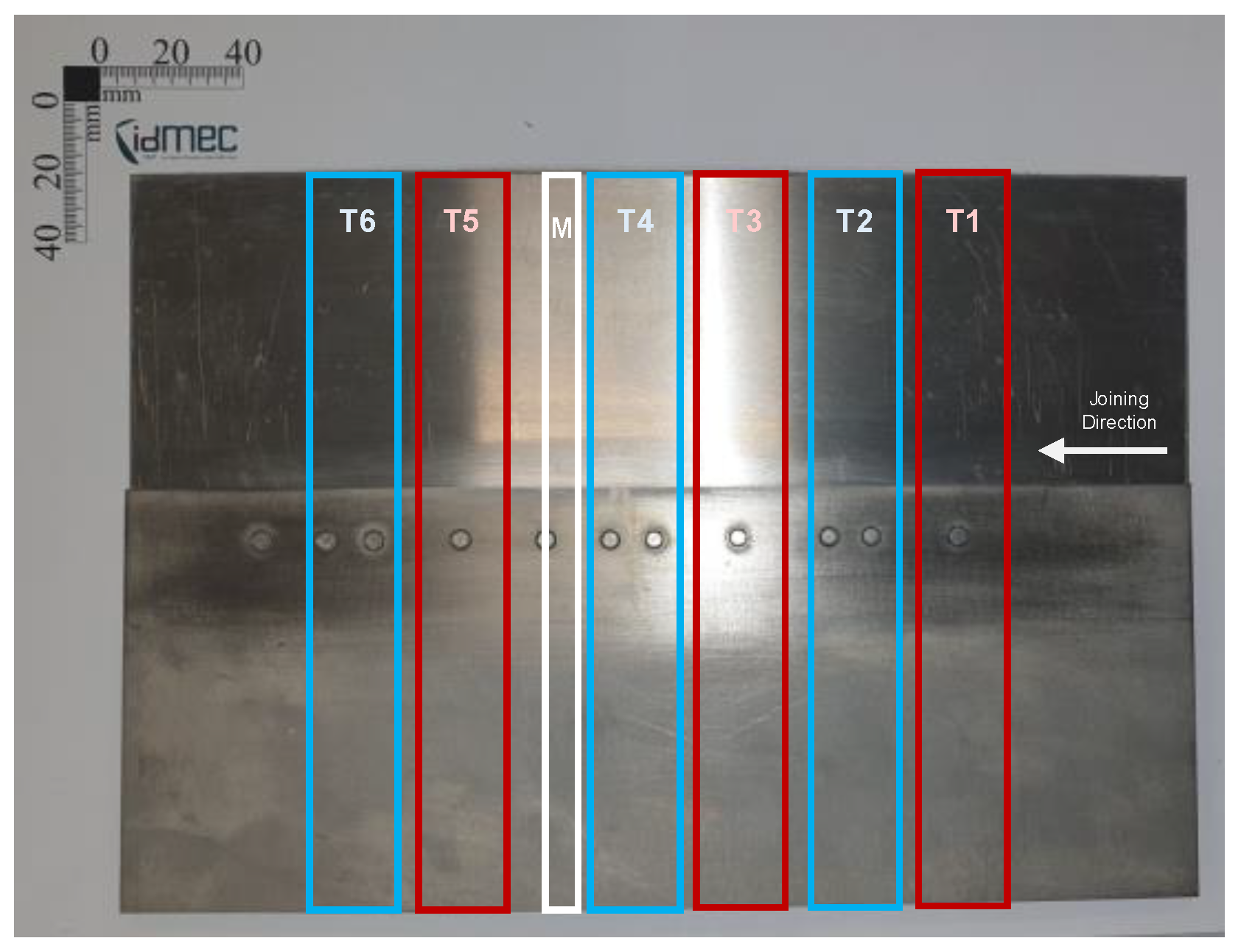
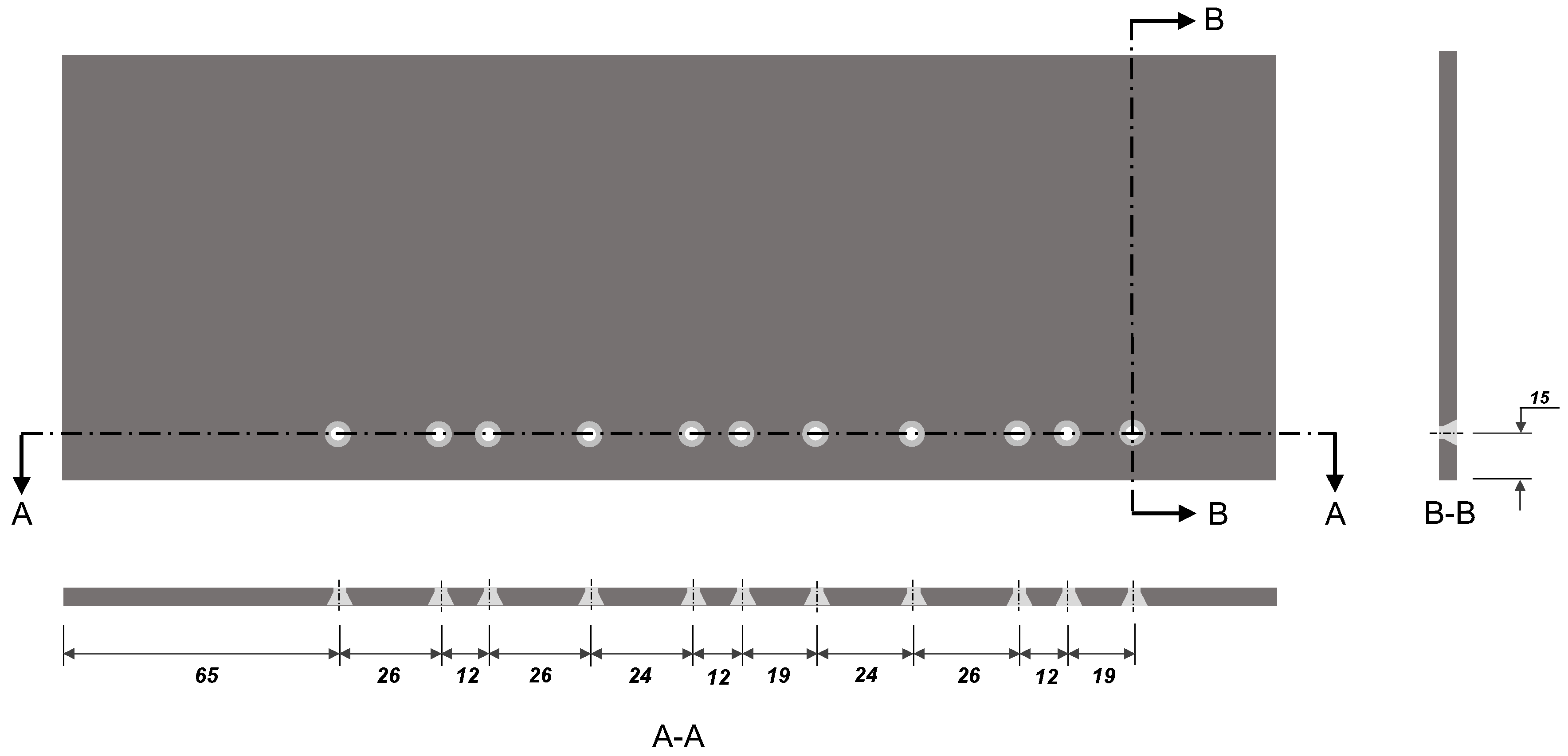
2. Materials and Methods

One of the selected base materials to fabricate the dissimilar AA-Ti joints was the aluminum alloy AA 7075-T651, a very high strength alloy that is heat treated with stress relief, containing Zinc as main alloying element, supplied as rolled plates with 3 mm of thickness. The second base material was the ASTM Grade 5 titanium alloy Ti-6Al-4V, another high strength material also with very good corrosion resistance, supplied in the form of 2 mm thick rolled sheets. The physical and mechanical properties of the materials are presented in Table 1 [15,16].
In order to produce the joints, both base materials were cut into 125 × 300 mm2 plates, placing the aluminum one on the top and on the advancing side (AS), whereas the titanium plate was positioned on the bottom of the joint and on the retreating side (RS). The overlap between base materials was set to 35 mm, as illustrated in the schematic depicted in Figure 1. The titanium plates were pre-drilled to create two types of profiles: each plate with holes with either a diameter of 3 or 4 mm, positioned as schematically represented in Figure 2. Furthermore, a chamfer was additionally performed on the holes, at the base of the plate, to promote better interlocking shape between the materials. This is expected to promote a connection similar to conventional riveting on the Ti plate, where the deformed material creates a rivet-head-like shape. Reference specimens were also produced by conventional riveting, for a qualitative comparison with the produced joints. The conventional riveting technique used consisted in riveting both aluminum and titanium pre-drilled plates with the corresponding diameters, to fit the commercially available aluminum conventional rivets of 3 and 4 mm in diameter. A standard manual riveting gun was used to deform the rivet heads and perform the connections.
The AA-Ti joints were produced on an ESAB LEGIO™ 3UL numeric control machine, using a position controlled process since, for these joints, it was only intended to deform the aluminum into the pre-existing profiles (holes in the titanium plates), without direct contact between the processing tool and the titanium. This type of process control can prevent such contact by keeping the penetration of the tool constant throughout the joining procedure. The FSW tool used in this work was a modular tool, consisting of a 5 mm diameter threaded tapered probe coupled with a 16 mm spiral grooved flat shoulder. In order to systematically study the produced joints, part of the Taguchi method was implemented, where an L4 (32) parameter matrix was set, with the rotational speed (ω), the hole diameter (HD) of the drilled profiles in the titanium plates and the joining speed (JS), which are the three variable process parameters under investigation. All of the used parameters and their levels are listed in Table 2.
Once the joints were produced, they were cut in the direction perpendicular to that of the tool path, into 25 mm wide specimens, to perform the quasi-static tensile shear tests (the TX specimens in Figure 3) and into a 12 mm wide specimen to perform the hardness tests and observe the cross-section under a microscope (the M specimen in Figure 3). The tensile shear specimens were designated as T1, T3 or T5, corresponding to the specimens with one connection point, and T2, T4 or T6, referring to the specimens with two connection points, highlighted with red and blue rectangles, respectively, and represented in Figure 3.

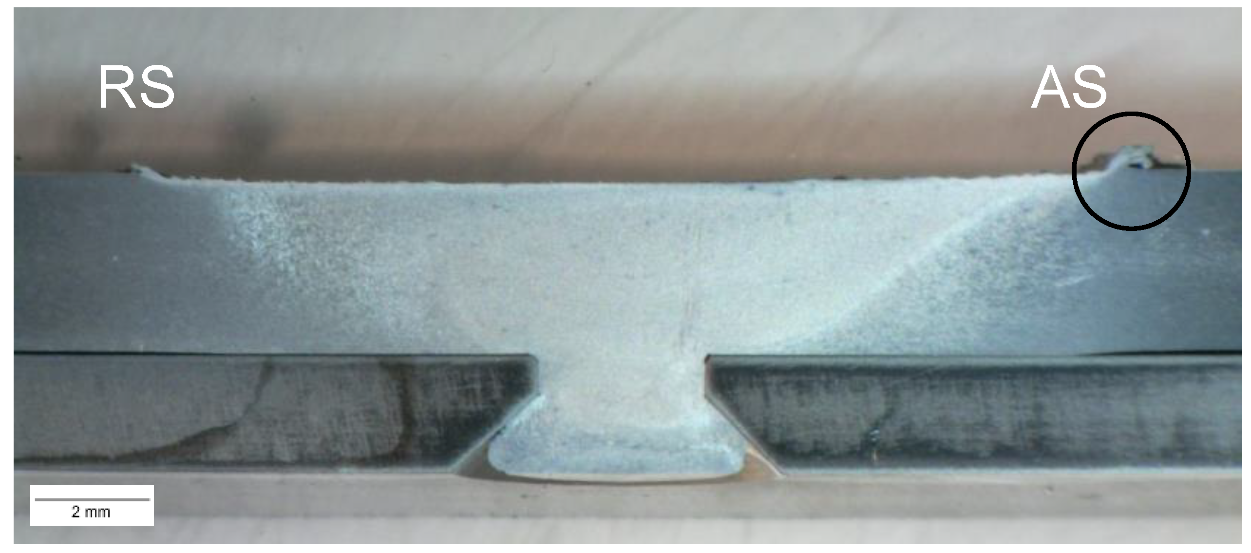
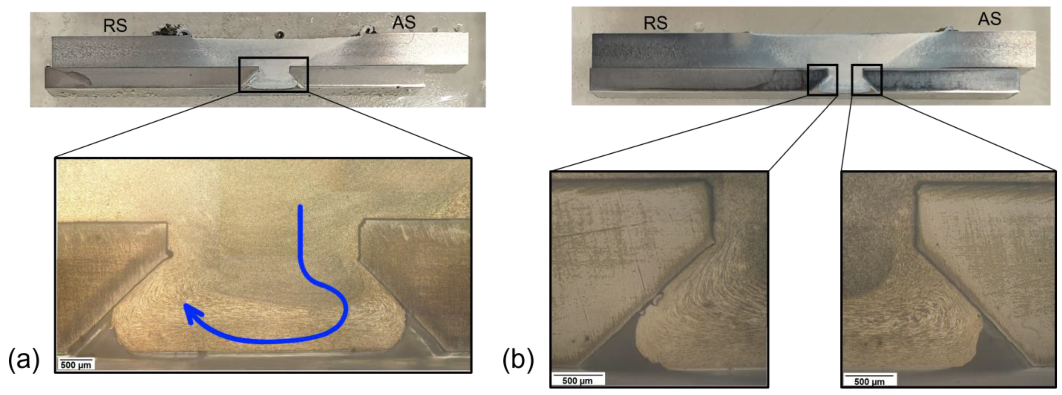
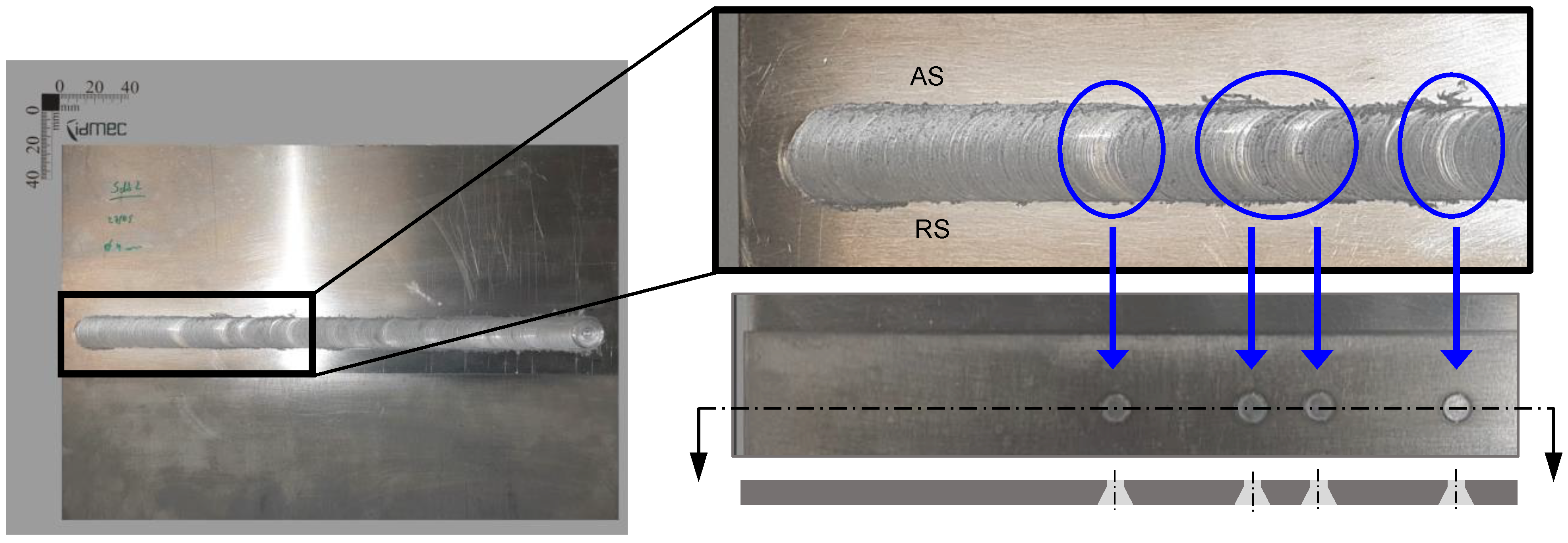
3. Experimental Results and Discussion

Upon visual analysis of the produced joints, all four fabricated AA-Ti joints showed very similar and smooth surface finishes, whereas none of them evidenced volumetric voids in the stir processed area of the material, resulting in successful joints. Despite the overall good surface quality, some of the joints evidenced minor amount of flash, visible in Figure 4, located in the perimeter of the weld seam, with no significant effect on mechanical performance. In all of the investigated conditions, the parameters used for the process generated a flow of material through the hole and a consolidation of the stirred aluminum, promoting a good filling of the drilled profiles in the titanium plate, which resulted in the successful joining of the materials together, as exemplified in Figure 4. Along the tool path at the joints’ top surface, a ‘color band’ scheme is possible to identify (see Figure 5), matching with the holes drilled in the titanium plate, where the material has been drained to create the aluminum pins. At these points, the pressure exerted was lower due to the material flow, so a lower heat generation rate is expected, as there is less intimate contact with the tool’s shoulder, which may have resulted in a local variation in the roughness and allowing these bands to be observed.
From Figure 6, the microstructural changes can be seen to have occurred, when compared to the base material, characterized by an outer zone with elongated grains. In contrast, the inner area is more characteristic of an equivalent stir zone in the conventional FSW process. The FSW tool probe, rotating in the clockwise direction, when passing through an area where there is a cavity to be filled, pushes material into it, creating a flow of stirred material that goes from the right side of the image (AS) to the left side (RS) and begins to rise. Figure 6 shows a schematic planar representation of this three-dimensional flow, and it can also be seen that the left side of the profile presents less compaction, unlike the right side, where this compaction is more evident, and the material shows a greater amount of more refined grains. This observed phenomenon needs to be investigated in-depth in a possible future work to understand if it affects the axisymmetric behavior of the material, influencing the mechanical performance of the connection, depending on the direction of the external loading that is applied.

3.1. Tensile Results

Quasi-static uniaxial tests were performed in order to determine the ultimate tensile lap-shear force (UTLF), using a testing machine INSTRON® 5566, equipped with a 10 kN load cell.
The typical load-displacement curves of the single lap shear tested specimens, under the quasi-static loading of the AA-Ti joints, are plotted in Figure 7a. For purely qualitative comparative purposes with the AA-Ti joints, conventional aluminum rivets with 3 and 4 mm in diameter (the R-3 and R-4 joints, respectively) were used to create riveted specimens in conventional form, identical to those produced by FSW, to make a preliminary qualitative comparison between these two joining technologies. Figure 7b shows, graphically, the mechanical performance of all of the tested joints, where it is possible to observe that the joints obtained by FSW exhibit higher values of mechanical performance, when compared to the produced riveted joints. Comparing the different parameter sets investigated, it is clear that for the smaller HD of 3 mm, the performance of condition E3 was considerably superior to that of condition E1. However, condition E3 yielded the results with the lowest consistency. This might be related to the higher heat delivered to the materials given the process parameters used for this condition., With the higher amount of energy applied to the material, it is expected to result in higher temperatures and a more softened state and a more fluid flow of the material into the drilled holes. Hence, the observed variability can result from a better filling, stronger connection, but it can also become locally less stable, as excessive softening can decrease the compaction applied to the material, resulting in a lower quality connection. This can characterize a potentially detrimental set of parameters. This sensitive issue of balancing the energy applied to the materials is easily found in literature when joining dissimilar materials by FSW [19]. It is also possible to observe that the tested FSW specimens with 4 mm of HD present a significant reduction in the standard deviation, which indicate that for the use of a 4 mm diameter for the drilled profiles, facilitated a more homogenous and sound flow of aluminum. A maximum UTLF of 5586 and 8151 N, for the specimens with one and two connection points, respectively, corresponding to an achieved maximum of remote stress of 74.5 and 108.7 MPa and 13 and 19% of joint efficiency. The remote stress was calculated considering the remote section, as suggested by Infante et al. [16]. The remote area considered for all joints was the cross-section of the material with the greater thickness. This simplification makes it possible to establish comparisons with other works published in the literature. Joint efficiency was determined by dividing the remote stress with the ultimate tensile strength of the base material (with a greater thickness, in each joint type). Although this provides an estimation for comparative purposes, given that no accurate non-destructive technique was used to determine the actual dimensions of the deformed material, e.g., X-ray tomography, the results are presented in load-displacement. In all tested joints, all fractures occurred in the same location, across the neck of the pin/rivet, parallel to the surface of the titanium, as expected, given the shearing applied.

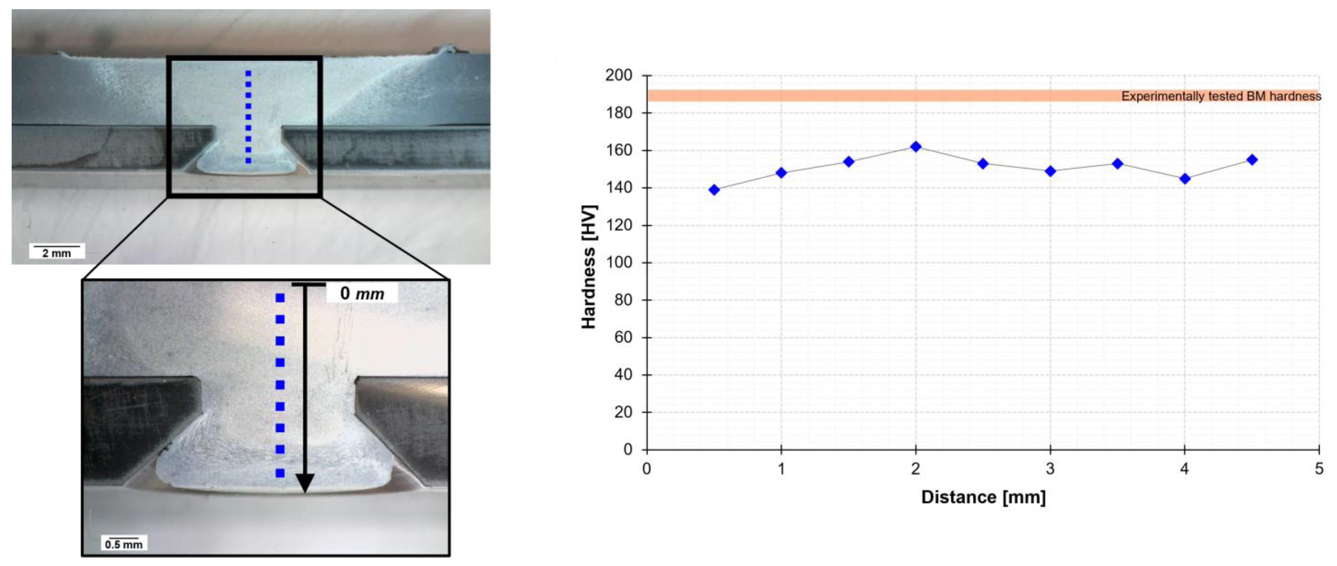
3.2. Microhardness Tests

In order to perform the hardness tests, to gather more information on the local properties of some of the joints, in an attempt to relate them to the fracture locations, a Shimadzu HMV-2 micro-hardness machine was used for the preliminary analysis, with a load of 0.2 HV (1.961 N) for 10 s, in a defined trajectory for each joint type, which is presented along with the discussion of the results.
In Figure 8, it is possible to observe the schematic representation of the location of the performed microhardness test (blue dots) following a straight line path (black arrow) along with the created pin, and the plotted results. It is clear that a reduction in the hardness value occurred, in relation to the experimental hardness of the base material (a decrease from 193.8 ± 1.3 HV to 150.9 ± 6.2 HV), being relatively constant along the depth of the pin profile. This is evidence of good flow and compaction of the material, as the hardness is relatively homogenous along the length of the pin. Although the cavity has not been completely filled, a good encasing of the material is visible, assuming the geometry of the original profile.

3.3. Statistical Analysis of the Effects of the Process Parameters on the Tensile Results

A statistical analysis of the process was conducted to assess the main effects and interactions of these parameters on the UTLF values. Since the test design is orthogonal, it is possible to separate the effect of each parameter in each level. Figure 9 shows the results obtained for the average UTLF values for each parameter at each level for all of the joints, in which the greater the slope, the greater the influence of the parameter on the response under study.
Following the analysis of the two charts depicted in Figure 9, it could firstly be concluded that, for the case of the joints with one connection point, the HD parameter had a lower effect than the variation of the other two parameters (ω and JS), which contributed to a more significant variation in the performance of the joints. Contrarily, in the joints with two connection points, the HD parameter causes the greatest variation. As expected, this is justified by the fact that, with a slight increase in this parameter results in a multiplicative effect, since there are two points of connection, causing them to experience twice the variation. For joints with one connection point, JS had the most significant effect on the UTLF, followed by ω and HD. For the case of the joints with two connection points, the order of significance was inverted, with the HD having the highest effect, followed by the JS and finally ω.

4. Conclusions

After experimental trials, the FSW process feasibility joining AA 7075-T651 and Ti-6AL-4V, aluminum and titanium alloys respectively, without intermixing the materials has been proven, avoiding concerns regarding IMC’s and the side effects it may induce. Joining such dissimilar materials using this FSW derived method also enables a one step process, avoiding the use of conventional joining methods and the disadvantages they entail.
The use of Taguchi method to define an L4 (32) orthogonal array to produce the AA-Ti joints in a systematically way, revealed to be an effective approach to achieve positive experimental results, decreasing the amount of required trials.
Significant mechanical performance levels were achieved in the lap shear tensile tests. For the joints with one and two connection points, the UTLF values above 1846 and 3737 N, respectively, were reached. All of the produced joints exhibited shear failure on the same location, across the neck pin, parallel to the titanium plate.
The hardness tests performed with the created connecting pins resulted in a hardness profile with a lower value than the base material but was relatively constant throughout the length of the pins, which evidences a good flow and compaction of the material.
From the conducted statistical analysis, when evaluating the joints fabricated with a single connection point, it was found that the joining speed had the most significant effect on the lap shear mechanical performance, followed by the rotational speed and the least governing parameter was the hole diameter. In contrast, in what refers to joints fabricated with two points of connection, the hole diameter was found to be the main governing parameter, evidencing the greatest influence on the mechanical performance, followed by the joining speed and, in this case, the rotational speed was found to be the parameter with the least influence on mechanical performance.

Author Contributions

Methodology, G.C.; Investigation, F.D.; Writing – review & editing, A.N.C. and D.F.O.B.; Supervision, P.M. and V.I. All authors have read and agreed to the published version of the manuscript.

Funding

This research received no external funding.

Data Availability Statement

The data presented in this study are available on request from the corresponding author.

Acknowledgments

This work was supported by FCT, through IDMEC under LAETA, project UIDB/50022/2020.

Conflicts of Interest

The authors declare no conflict of interest.

References

  1. Correia, A.N.; Braga, D.F.O.; Moreira, P.M.; Infante, V. Review on dissimilar structures joints failure. Eng. Fail. Anal. 2021, 129, 105652. [Google Scholar] [CrossRef]
  2. Batistão, B.F.; Bergmann, L.A.; Gargarella, P.; de Alcântara, N.G.; dos Santos, J.F.; Klusemann, B. Characterization of dissimilar friction stir welded lap joints of AA5083 and GL D36 steel. J. Mater. Res. Technol. 2020, 9, 15132–15142. [Google Scholar] [CrossRef]
  3. A, S.S.; Kumar, A.; Mugada, K.K. Investigation of material flow, microstructure evolution, and texture development in dissimilar friction stir welding of Al6061 to Ti6Al4V. Mater. Today Commun. 2022, 33. [Google Scholar] [CrossRef]
  4. Jandaghi, M.R.; Pouraliakbar, H.; Hong, S.I.; Pavese, M. Grain boundary transition associated intergranular failure analysis at TMAZ/SZ interface of dissimilar AA7475-AA2198 joints by friction stir welding. Mater. Lett. 2020, 280, 128557. [Google Scholar] [CrossRef]
  5. Jandaghi, M.; Pouraliakbar, H.; Saboori, A.; Hong, S.; Pavese, M. Comparative Insight into the Interfacial Phase Evolutions during Solution Treatment of Dissimilar Friction Stir Welded AA2198-AA7475 and AA2198-AA6013 Aluminum Sheets. Materials 2021, 14, 1290. [Google Scholar] [CrossRef] [PubMed]
  6. Amancio-Filho, S.T.; Dos Santos, J.F. Joining of polymers and polymer-metal hybrid structures: Recent developments and trends. Polym. Eng. Sci. 2009, 49, 1461–1476. [Google Scholar] [CrossRef]
  7. Mishra, R.S.; Ma, Z.Y. Friction stir welding and processing. Mater. Sci. Eng. R Rep. 2005, 50, 1–78. [Google Scholar] [CrossRef]
  8. Shehabeldeen, T.A.; Yin, Y.; Ji, X.; Shen, X.; Zhang, Z.; Zhou, J. Investigation of the microstructure, mechanical properties and fracture mechanisms of dissimilar friction stir welded aluminium/titanium joints. J. Mater. Res. Technol. 2021, 11, 507–518. [Google Scholar] [CrossRef]
  9. Yu, M.; Zhao, H.; Jiang, Z.; Guo, F.; Zhou, L.; Song, X. Microstructure and mechanical properties of friction stir lap AA6061-Ti6Al4V welds. J. Mater. Process. Technol. 2019, 270, 274–284. [Google Scholar] [CrossRef]
  10. Evans, W.T.; Gibson, B.T.; Reynolds, J.T.; Strauss, A.M.; Cook, G.E. Friction Stir Extrusion: A new process for joining dissimilar materials. Manuf. Lett. 2015, 5, 25–28. [Google Scholar] [CrossRef]
  11. Evans, W.T.; Cook, G.E.; Strauss, A.M. Joining Aerospace Aluminum 2024-T4 to Titanium by Friction Stir Extrusion. Friction Stir Welding and Processing IX; Springer: Berlin/Heidelberg, Germany, 2017; pp. 79–89. [Google Scholar] [CrossRef]
  12. Gagliardi, F.; Ambrogio, G.; Conte, R.; Bambach, M. Extruded joining elements manufactured by friction stir forming: An investigation of the process parameters. Int. J. Adv. Manuf. Technol. 2020, 106, 5559–5570. [Google Scholar] [CrossRef]
  13. Saju, T.P.; Narayanan, R.G. Dieless friction stir extrusion joining of aluminum alloy sheets with a pinless stir tool by controlling tool plunge depth. J. Mater. Process. Technol. 2020, 276. [Google Scholar] [CrossRef]
  14. Bunaziv, I.; Akselsen, O.M.; Ren, X.; Nyhus, B.; Eriksson, M.; Gulbrandsen-Dahl, S. A Review on Laser-Assisted Joining of Aluminium Alloys to Other Metals. Metals 2021, 11, 1680. [Google Scholar] [CrossRef]
  15. Davis, J.R. ASM Specialty Handbook: Aluminum and Aluminum Alloys; ASM International: Materials Park, OH, USA, 1993. [Google Scholar]
  16. MatWeb. Titanium Ti-6Al-4V (Grade 5). [cited 2021 Sep. 6]. Available online: http://www.matweb.com/search/DataSheet.aspx?MatGUID=b350a789eda946c6b86a3e4d3c577b39 (accessed on 6 September 2021).
  17. Mehta, K.P.; Badheka, V.J. A Review on Dissimilar Friction Stir Welding of Copper to Aluminum - Process, Properties, and Variants. Mater. Manuf. Process. 2016, 31, 233–254. [Google Scholar]
  18. Rossi, S.; Russo, F.; Lemmi, A.M.; Benedetti, M.; Fontanari, V. Fatigue Corrosion Behavior of Friction Welded Dissimilar Joints in Different Testing Conditions. Metals 2020, 10, 1018. [Google Scholar] [CrossRef]
  19. Infante, V.; Braga, D.; Duarte, F.; Moreira, P.; de Freitas, M.; de Castro, P. Study of the fatigue behaviour of dissimilar aluminium joints produced by friction stir welding. Int. J. Fatigue 2016, 82, 310–316. [Google Scholar] [CrossRef]
Figure 1. Schematic representation of the joining setup configuration for the AA-Ti joints – aluminum alloy placed on top and advancing side of the joint.
Metals 13 00249 g001
Figure 2. Scheme of the geometry and the relative position of the profiles drilled in titanium sheets (back view). All dimensions in mm.
Metals 13 00249 g002
Figure 3. Back view of an AA-Ti produced joint, with a schematic representation of the location of the cut specimens. Joints with single and double connection points highlighted by red and blue rectangles, respectively.
Metals 13 00249 g003
Figure 4. Detailed view of the cross-section of condition E3, in the middle of the created aluminum pin. Generated flash highlighted by the black circle.
Metals 13 00249 g004
Figure 5. Detail top of joint E4, with highlight observing the ‘color bands’ which correspond to the holes where the material was drained.
Metals 13 00249 g005
Figure 6. Detailed view of (a) cross-section of condition E3, where a two-dimensional arrow represents the three-dimensional flow of the material schematically, and (b) cross-section of condition E1 that was Kroll etched during 10 s for detailed material flow around the titanium plate chamfered holes.
Metals 13 00249 g006
Figure 7. (a) Load-displacement curve of all of the tested specimens of condition E2 with one connection point; (b) mechanical performance of the produced joints and riveted connections with one and two connection points [R-3 and R-4: riveted joints; E1, E2, E3 and E4: AA-Ti joints produced by FSW].
Metals 13 00249 g007
Figure 8. Cross-sectional view of joint E1, with the identification of the measured distance in the microhardness test and the plotted results of the tested line. Blue dots represent the testing locations while the black arrow corresponds to the reference of the testing path.
Metals 13 00249 g008
Figure 9. Plots of the mean effect of the process parameters on the UTLF in the (a) AA-Ti joints with one and (b) AA-Ti joints with two connections points.
Metals 13 00249 g009
Table 1. Physical and mechanical properties of the base materials used to produce dissimilar joints: AA 7075-T651 [15] and Ti-6Al-4V [16].
MaterialDensity
[kg/m3]
Ultimate Tensile Strength
[MPa]
Elongation at Break
[%]
Hardness
[17]
Thermal Conductivity
[W/(m·K)]
Melting Temperature
[°C]
AA 7075280057211193.8 ± 1.3 *170477–635
Ti-6Al-4V44301170103966.71604–1660
* Experimentally obtained.
Table 2. The L4 orthogonal array for three parameters with three levels each, and the constant parameters in the AA-Ti joints and their levels.
JointVariable Parameters
ω [RPM]HD [18]JS [cm/min]
E180036
E247
E3100037
E446
Constant Parameters
Tilt Angle [°]1.5
FSW Process ControlPosition
Rotation DirectionCW
Plunge Speed [mm/s]0.1
Dwell Time [s]10
Welding Position [18]2.1
Probe Length [18]2.8
Disclaimer/Publisher’s Note: The statements, opinions and data contained in all publications are solely those of the individual author(s) and contributor(s) and not of MDPI and/or the editor(s). MDPI and/or the editor(s) disclaim responsibility for any injury to people or property resulting from any ideas, methods, instructions or products referred to in the content.

