

Fabrication of Electron Beam Melted Titanium Aluminide: The Effects of Machining Parameters and Heat Treatment on Surface Roughness and Hardness

 , , , , and
Abstract
:1. Introduction
2. Materials and Methods
2.1. Production of TiAl Samples with E-PBF
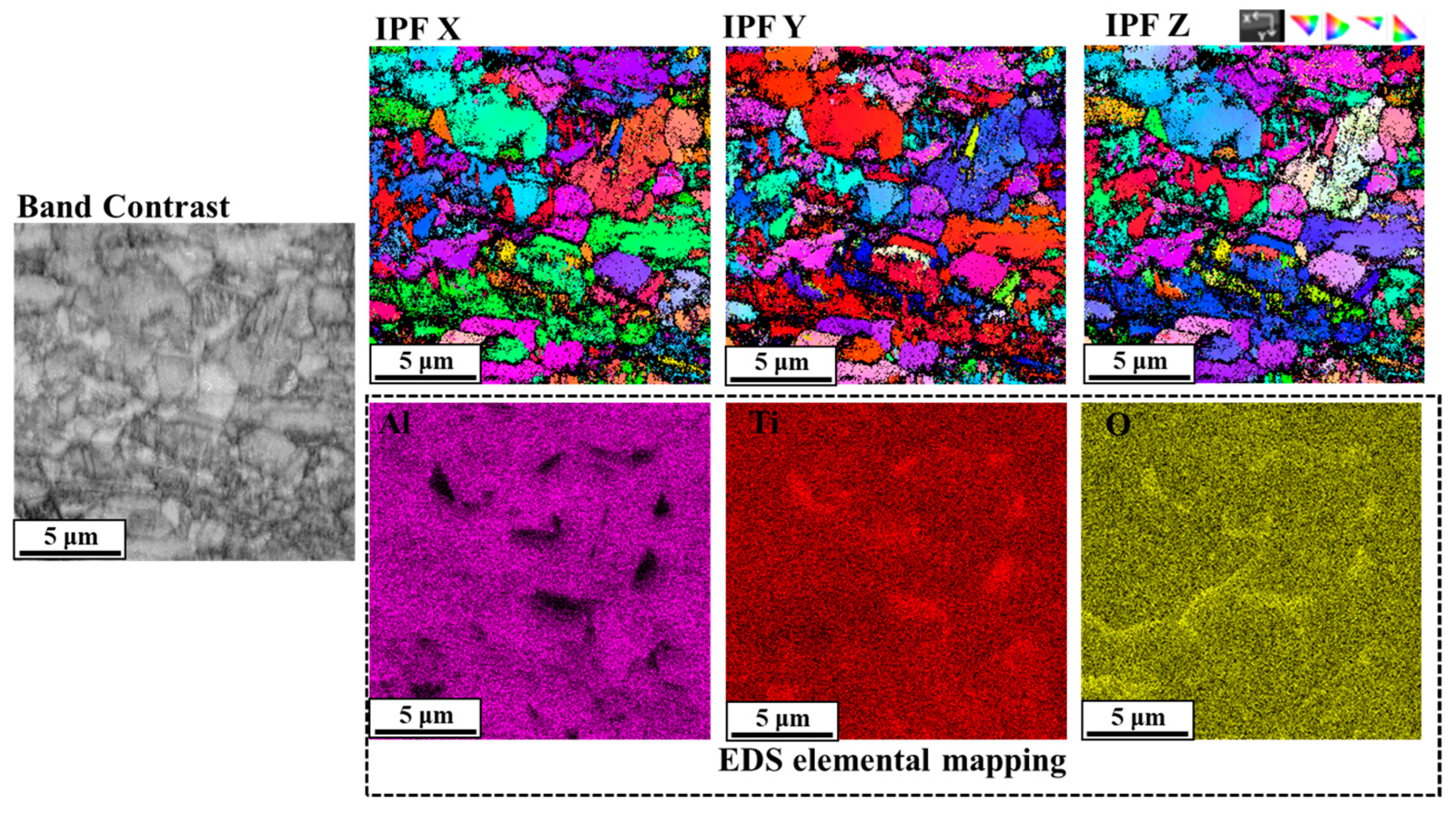
2.2. Microstructural Characterization
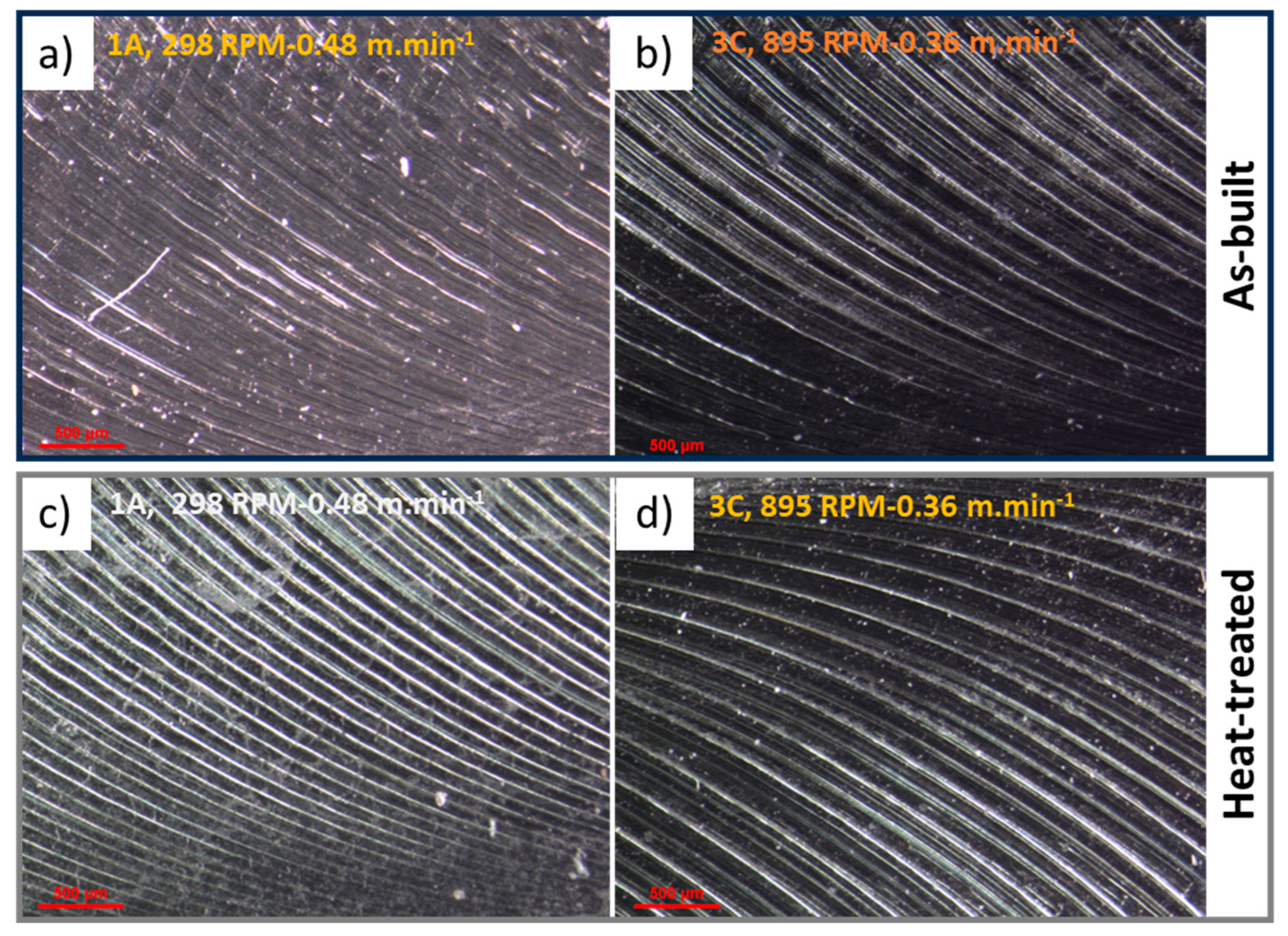
2.3. Machining and Hardness Tests
3. Results and Discussion
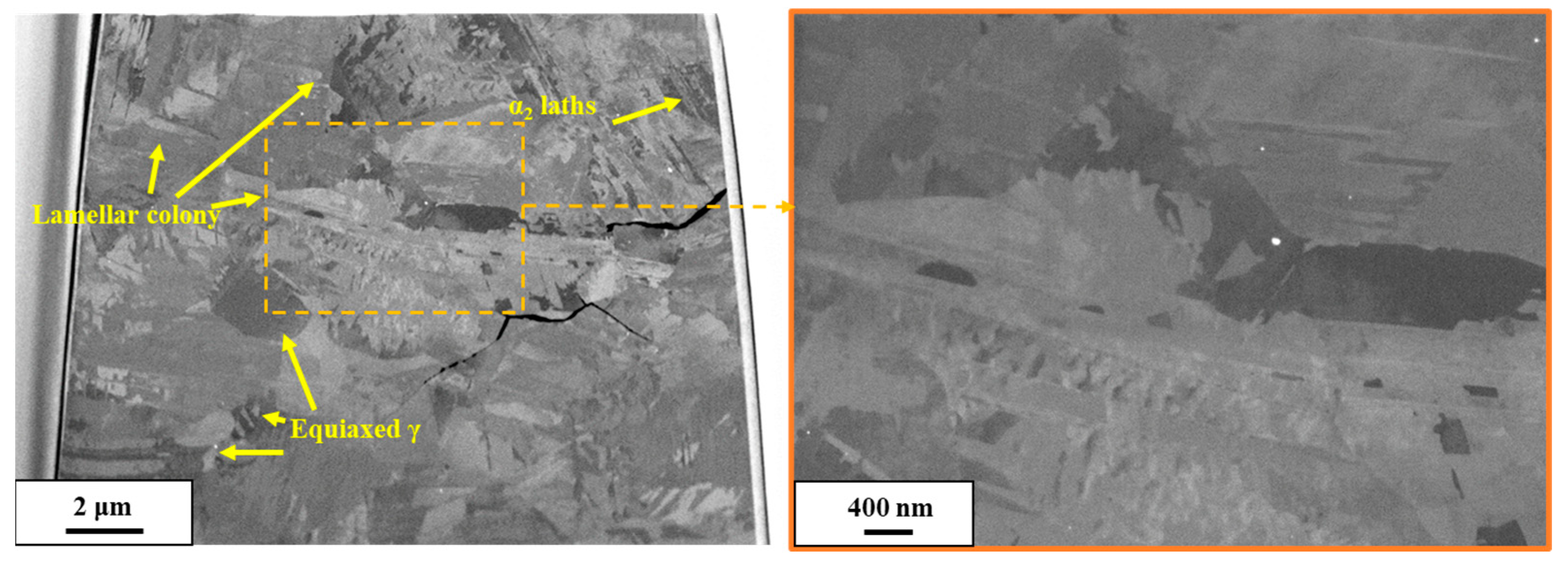
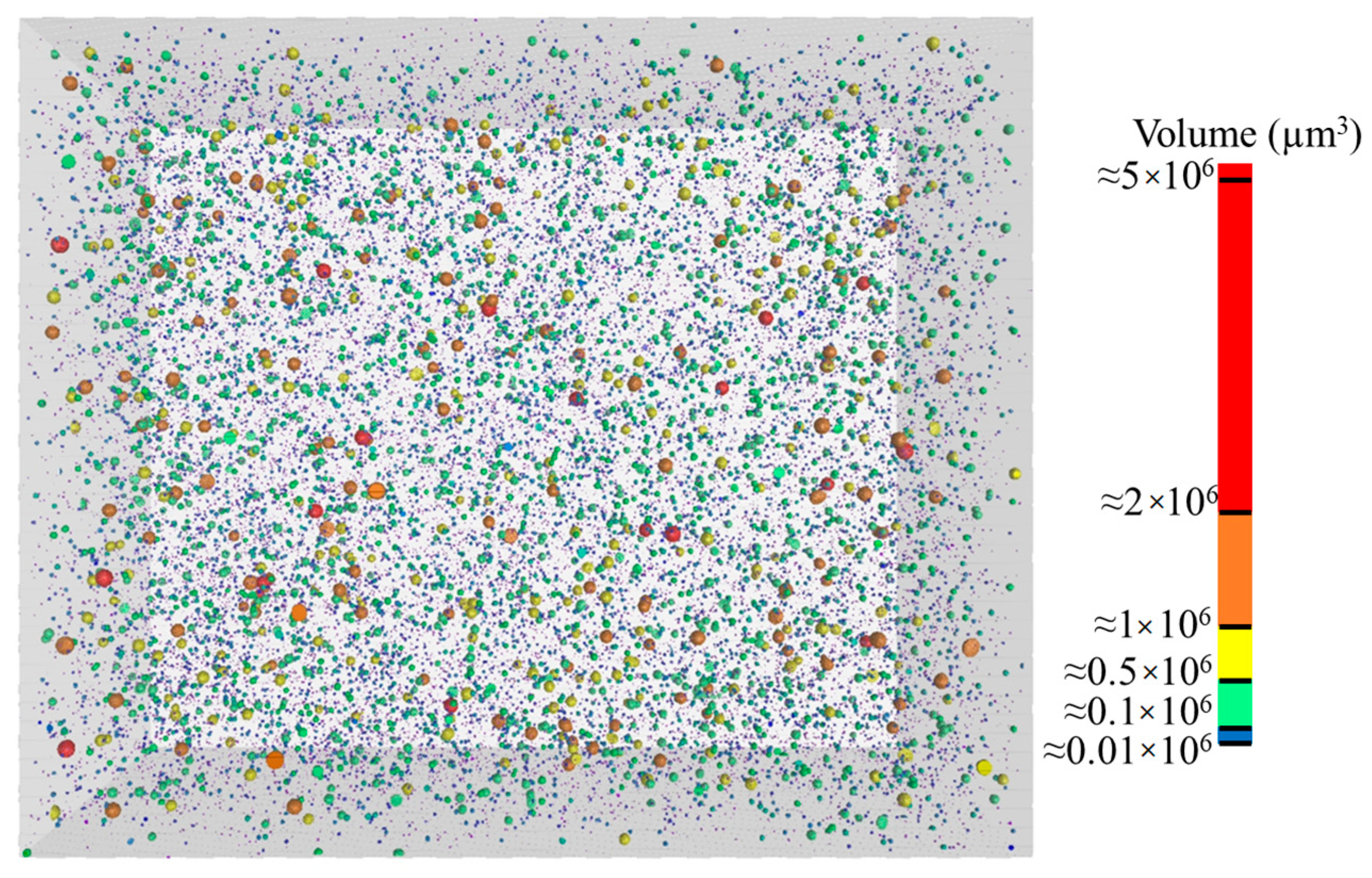
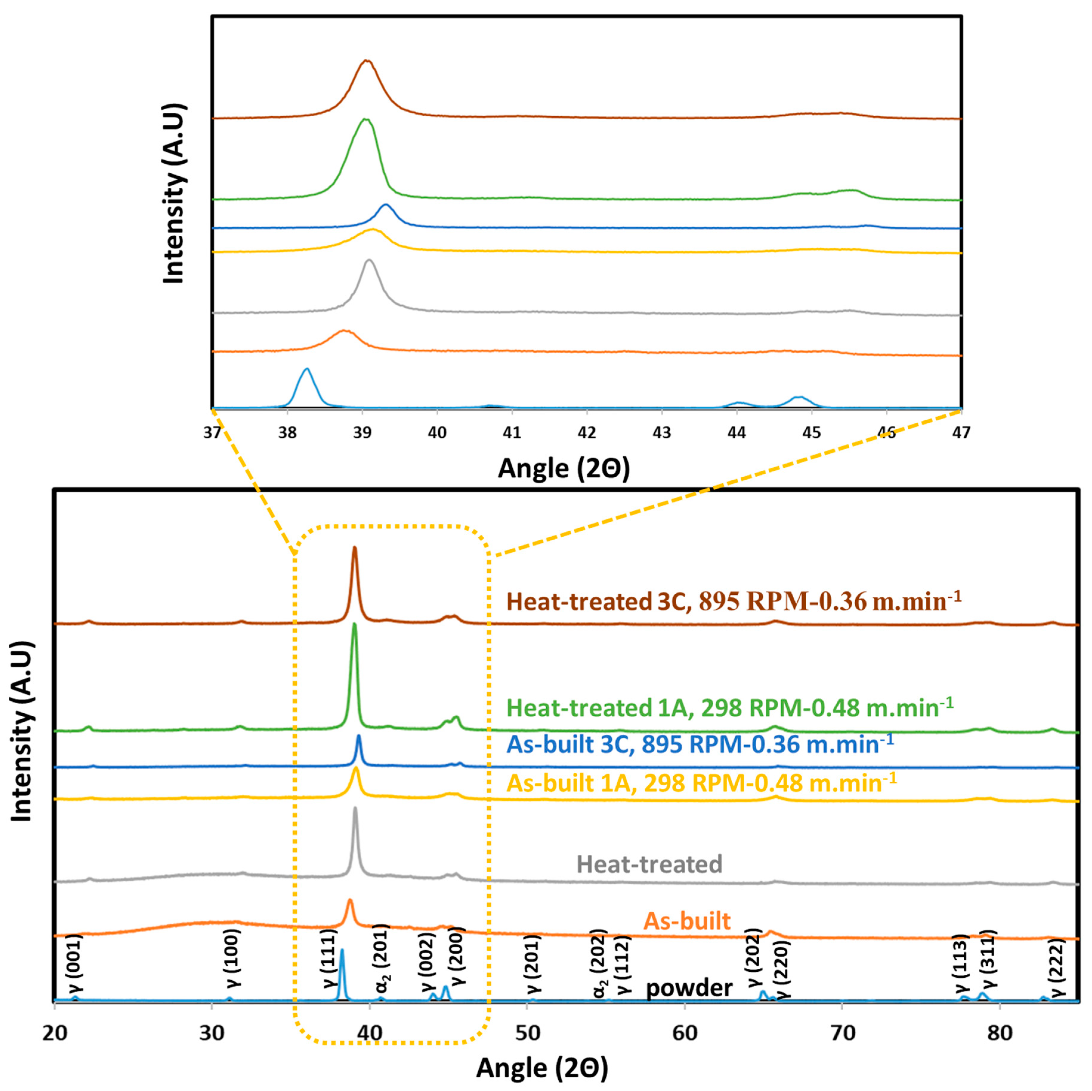
3.1. Microstructural Characterization
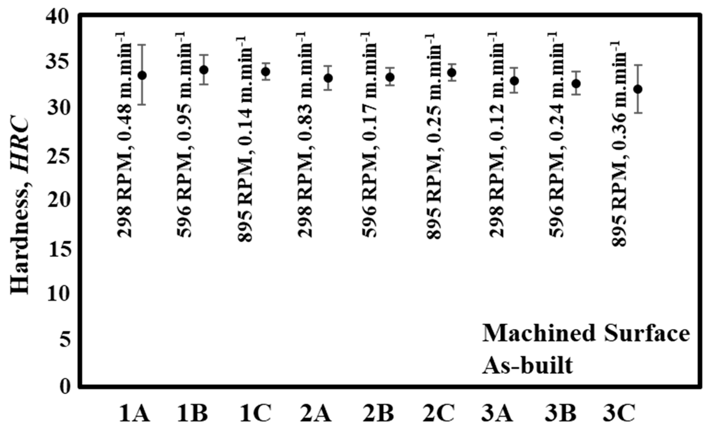
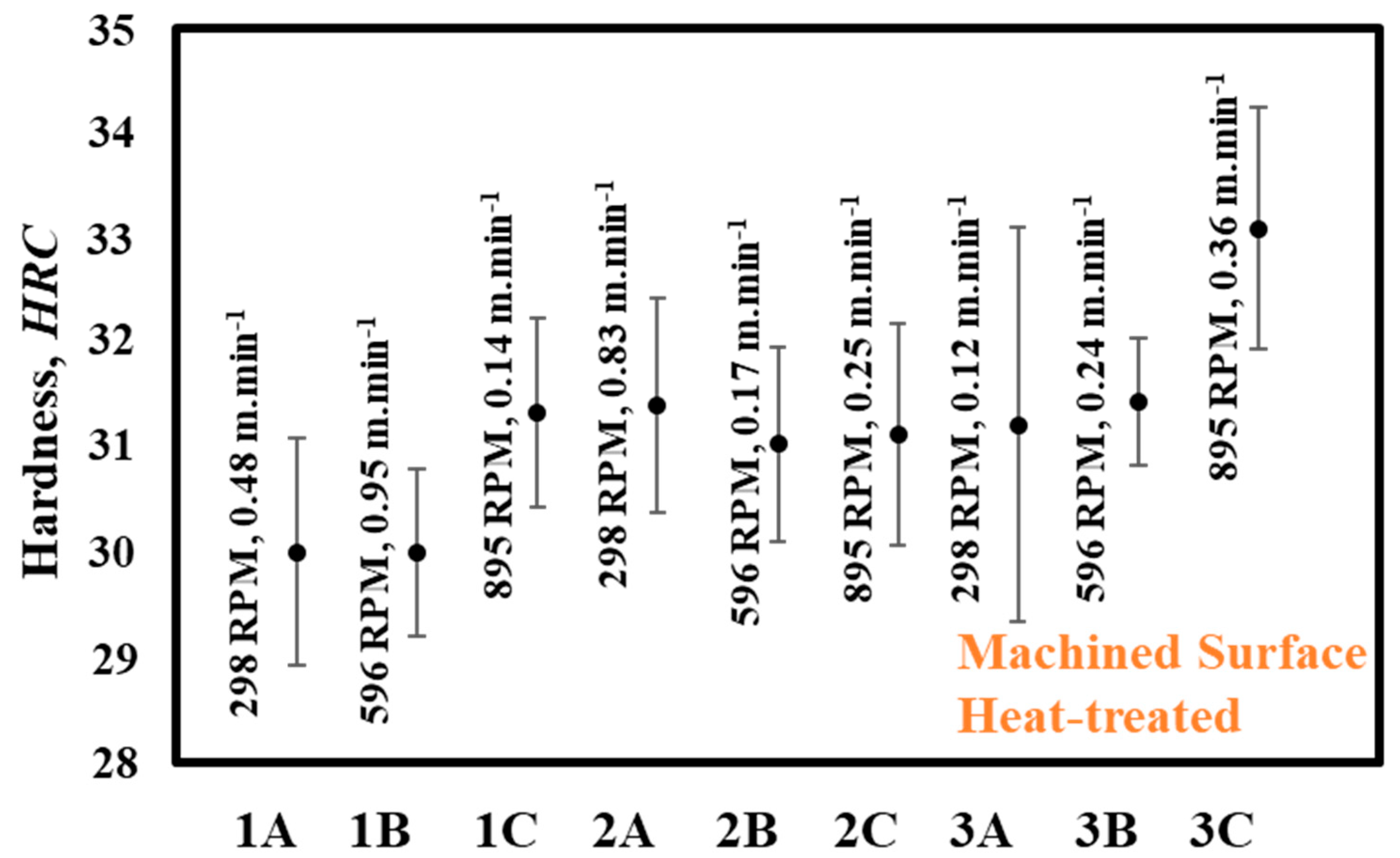
3.2. Hardness Measurements
4. Conclusions
Author Contributions
Funding
Data Availability Statement
Conflicts of Interest
References
- Voice, W.E.; Henderson, M.; Shelton, E.F.J.; Wu, X. Gamma titanium aluminide, TNB. Intermetallics 2005, 13, 959–964. [Google Scholar] [CrossRef]
- Appel, F.; Paul, J.D.H.; Oehring, M. Gamma Titanium Aluminide Alloys: Science and Technology; Wiley: Weinheim, Germany, 2011; Available online: https://books.google.com.tr/books?id=dJUh4rdN41cC (accessed on 15 September 2011).
- Tetsui, T. Development of a TiAl turbocharger for passenger vehicles. Mater. Sci. Eng. A 2002, 329–331, 582–588. [Google Scholar] [CrossRef]
- Tetsui, T.; Ono, S. Endurance and composition and microstructure effects on endurance of TiAl used in turbochargers. Intermetallics 1999, 7, 689–697. [Google Scholar] [CrossRef]
- Gebauer, K. Performance, tolerance and cost of TiAl passenger car valves. Intermetallics 2006, 14, 355–360. [Google Scholar] [CrossRef]
- Murr, L.E.; Gaytan, S.M.; Ceylan, A.; Martinez, E.; Martinez, J.L.; Hernandez, D.H.; Machado, B.I.; Ramirez, D.A.; Medina, F.; Collins, S.; et al. Characterization of titanium aluminide alloy components fabricated by additive manufacturing using electron beam melting. Acta Mater. 2010, 58, 1887–1894. [Google Scholar] [CrossRef]
- Tetsui, T.; Shindo, K.; Kaji, S.; Kobayashi, S.; Takeyama, M. Fabrication of TiAl components by means of hot forging and machining. Intermetallics 2005, 13, 971–978. [Google Scholar] [CrossRef]
- Cho, K.; Kawabata, H.; Hayashi, T.; Yasuda, H.Y.; Nakashima, H.; Takeyama, M.; Nakano, T. Peculiar microstructural evolution and tensile properties of β-containing γ-TiAl alloys fabricated by electron beam melting. Addit. Manuf. 2021, 46, 102091. [Google Scholar] [CrossRef]
- Renjie, C.; Ming, G.; Hu, Z.; Shengkai, G. Interactions between TiAl alloys and yttria refractory material in casting process. J. Mater. Process. Technol. 2010, 210, 1190–1196. [Google Scholar] [CrossRef]
- Fröhlich, M.; Braun, R.; Leyens, C. Oxidation resistant coatings in combination with thermal barrier coatings on γ-TiAl alloys for high temperature applications. Surf. Coat. Technol. 2006, 201, 3911–3917. [Google Scholar] [CrossRef]
- Nouri, S.; Rastegari, S.; Mirdamadi, S.; Hadavi, M. Microstructure and oxidation resistance of Si modified aluminide coating on TiAl based alloys. Surf. Eng. 2015, 31, 930–933. [Google Scholar] [CrossRef]
- Akca, E.; Gürsel, A. A Review on Superalloys and IN718 Nickel-Based INCONEL Superalloy. Period. Eng. Nat. Sci. 2015, 3, 15–27. [Google Scholar] [CrossRef]
- Chaturvedi, M.C.; Han, Y. Strengthening mechanisms in Inconel 718 superalloy. Met. Sci. 1983, 17, 145–149. [Google Scholar] [CrossRef]
- Gribbin, S.; Bicknell, J.; Jorgensen, L.; Tsukrov, I.; Knezevic, M. Low cycle fatigue behavior of direct metal laser sintered Inconel alloy 718. Int. J. Fatigue 2016, 93, 156–167. [Google Scholar] [CrossRef]
- Hadadzadeh, A.; Amirkhiz, B.S.; Li, J.; Mohammadi, M. Columnar to equiaxed transition during direct metal laser sintering of AlSi10Mg alloy: Effect of building direction. Addit. Manuf. 2018, 23, 121–131. [Google Scholar] [CrossRef]
- Mohammadi, M.; Asgari, H. Achieving low surface roughness AlSi10Mg_200C parts using direct metal laser sintering. Addit. Manuf. 2018, 20, 23–32. [Google Scholar] [CrossRef]
- Bagherzadeh, A.; Koc, B.; Budak, E.; Isik, M. High-speed machining of additively manufactured Inconel 718 using hybrid cryogenic cooling methods. Virtual Phys. Prototyp. 2022, 17, 419–436. [Google Scholar] [CrossRef]
- Niaki, M.K.; Torabi, S.A.; Nonino, F. Why manufacturers adopt additive manufacturing technologies: The role of sustainability. J. Clean. Prod. 2019, 222, 381–392. [Google Scholar] [CrossRef]
- Mojtaba, K.N. Economic sustainability of additive manufacturing. J. Manuf. Technol. Manag. 2019, 30, 353–365. [Google Scholar] [CrossRef]
- Khan, S.; Fayazbakhsh, K.; Fawaz, Z.; Arian Nik, M. Curvilinear variable stiffness 3D printing technology for improved open-hole tensile strength. Addit. Manuf. 2018, 24, 378–385. [Google Scholar] [CrossRef]
- Dickson, A.N.; Dowling, D.P. Enhancing the bearing strength of woven carbon fibre thermoplastic composites through additive manufacturing. Compos. Struct. 2019, 212, 381–388. [Google Scholar] [CrossRef]
- Rahmati, S. Direct Rapid Tooling; Elsevier: Amsterdam, The Netherlands, 2014. [Google Scholar] [CrossRef]
- Isik, M. Additive manufacturing and characterization of a stainless steel and a nickel alloy. Mater. Test. 2023, 65, 378–388. [Google Scholar] [CrossRef]
- Fan, S.; He, B.; Liu, M. Effect of Pulse Current Density on Microstructure of Ti-6Al-4V Alloy by Laser Powder Bed Fusion. Metals 2022, 12, 1327. [Google Scholar] [CrossRef]
- Jiang, C.P.; Wibisono, A.T.; Wang, S.H.; Pasang, T.; Ramezani, M. Selective Laser Melting of Free-Assembled Stainless Steel 316L Hinges: Optimization of Volumetric Laser Energy Density and Joint Clearance. Metals 2022, 12, 1223. [Google Scholar] [CrossRef]
- Megahed, S.; Bühring, J.; Duffe, T.; Bach, A.; Schröder, K.U.; Schleifenbaum, J.H. Effect of Heat Treatment on Ductility and Precipitation Size of Additively Manufactured AlSi10Mg. Metals 2022, 12, 1311. [Google Scholar] [CrossRef]
- Mian, M.J.; Razmi, J.; Ladani, L. Grain Scale Investigation of the Mechanical Anisotropic Behavior of Electron Beam Powder Bed Additively Manufactured Ti6Al4V Parts. Metals 2022, 12, 163. [Google Scholar] [CrossRef]
- Sreekanth, S.; Ghassemali, E.; Hurtig, K.; Joshi, S. Effect of Direct Energy Deposition Process Parameters. Metals 2020, 10, 96. [Google Scholar] [CrossRef]
- Kim, K.H.; Jung, C.H.; Jeong, D.Y.; Hyun, S.K. Preventing evaporation products for high-quality metal film in directed energy deposition: A review. Metals 2021, 11, 353. [Google Scholar] [CrossRef]
- Ramiro, P.; Galarraga, H.; Pérez-Checa, A.; Ortiz, M.; Alberdi, A.; Bhujangrao, T.; Morales, E.; Ukar, E. Effect of Heat Treatment on the Microstructure and Hardness of Ni-Based Alloy 718 in a Variable Thickness Geometry Deposited by Powder fed Directed Energy Deposition. Metals 2022, 12, 952. [Google Scholar] [CrossRef]
- Dinh, T.D.; Vanwalleghem, J.; Xiang, H.; Erdelyi, H.; Craeghs, T.; Paepegem, W. Van A unified approach to model the effect of porosity and high surface roughness on the fatigue properties of additively manufactured Ti6-Al4-V alloys. Addit. Manuf. 2020, 33, 101139. [Google Scholar] [CrossRef]
- Shrestha, R.; Simsiriwong, J.; Shamsaei, N. Fatigue behavior of additive manufactured 316L stainless steel parts: Effects of layer orientation and surface roughness. Addit. Manuf. 2019, 28, 23–38. [Google Scholar] [CrossRef]
- Oyelola, O.; Crawforth, P.; M’Saoubi, R.; Clare, A.T. On the machinability of directed energy deposited Ti6Al4V. Addit. Manuf. 2018, 19, 39–50. [Google Scholar] [CrossRef]
- Tyagi, P.; Goulet, T.; Riso, C.; Stephenson, R.; Chuenprateep, N.; Schlitzer, J.; Benton, C.; Garcia-Moreno, F. Reducing the roughness of internal surface of an additive manufacturing produced 316 steel component by chempolishing and electropolishing. Addit. Manuf. 2019, 25, 32–38. [Google Scholar] [CrossRef]
- Sankara Narayanan, T.S.N.; Kim, J.; Jeong, H.E.; Park, H.W. Enhancement of the surface properties of selective laser melted maraging steel by large pulsed electron-beam irradiation. Addit. Manuf. 2020, 33, 101125. [Google Scholar] [CrossRef]
- Nagalingam, A.P.; Yeo, S.H. Surface finishing of additively manufactured Inconel 625 complex internal channels: A case study using a multi-jet hydrodynamic approach. Addit. Manuf. 2020, 36, 101428. [Google Scholar] [CrossRef]
- Mingear, J.; Zhang, B.; Hartl, D.; Elwany, A. Effect of process parameters and electropolishing on the surface roughness of interior channels in additively manufactured nickel-titanium shape memory alloy actuators. Addit. Manuf. 2019, 27, 565–575. [Google Scholar] [CrossRef]
- Bagherzadeh, A.; Budak, E. Investigation of machinability in turning of difficult-to-cut materials using a new cryogenic cooling approach. Tribol. Int. 2018, 119, 510–520. [Google Scholar] [CrossRef]
- Bagherzadeh, A.; Kuram, E.; Budak, E. Experimental evaluation of eco-friendly hybrid cooling methods in slot milling of titanium alloy. J. Clean. Prod. 2021, 289, 125817. [Google Scholar] [CrossRef]
- Binali, R.; Demirpolat, H.; Kunto, M. Different Aspects of Machinability in Turning of AISI 304 Stainless Steel: A Sustainable Approach with MQL Technology. Metals 2023, 13, 1088. [Google Scholar] [CrossRef]
- Kaynak, Y.; Kitay, O. The effect of post-processing operations on surface characteristics of 316L stainless steel produced by selective laser melting. Addit. Manuf. 2019, 26, 84–93. [Google Scholar] [CrossRef]
- Devillez, A.; Le Coz, G.; Dominiak, S.; Dudzinski, D. Dry machining of Inconel 718, workpiece surface integrity. J. Mater. Process. Technol. 2011, 211, 1590–1598. [Google Scholar] [CrossRef]
- Dudzinski, D.; Devillez, A.; Moufki, A.; Larrouquère, D.; Zerrouki, V.; Vigneau, J. A review of developments towards dry and high speed machining of Inconel 718 alloy. Int. J. Mach. Tools Manuf. 2004, 44, 439–456. [Google Scholar] [CrossRef]
- Li, G.; Rashid, R.A.R.; Ding, S.; Sun, S.; Palanisamy, S. Machinability Analysis of Finish-Turning Operations for Ti6Al4V Tubes Fabricated by Selective Laser Melting. Metals 2022, 12, 806. [Google Scholar] [CrossRef]
- Beranoagirre, A.; López De Lacalle, L.N. Topography prediction on milling of emerging aeronautical Ti alloys. Phys. Procedia 2011, 22, 136–143. [Google Scholar] [CrossRef]
- Hood, R.; Aspinwall, D.K.; Soo, S.L.; Mantle, A.L.; Novovic, D. Workpiece surface integrity when slot milling γ-TiAl intermetallic alloy. CIRP Ann.-Manuf. Technol. 2014, 63, 53–56. [Google Scholar] [CrossRef]
- Klocke, F.; Settineri, L.; Lung, D.; Claudio, P.; Arft, M. High performance cutting of gamma titanium aluminides: Influence of lubricoolant strategy on tool wear and surface integrity. Wear 2013, 302, 1136–1144. [Google Scholar] [CrossRef]
- Sharman, A.R.C.; Aspinwall, D.K.; Dewes, R.C.; Bowen, P. Workpiece surface integrity considerations when finish turning gamma titanium aluminide. Wear 2001, 249, 473–481. [Google Scholar] [CrossRef]
- Zhu, L.; Chen, Y. Study on the Cutting Performance and Machinability of Gamma Titanium Aluminide. J. Appl. Sci. 2013, 13, 3774–3777. [Google Scholar] [CrossRef]
- He, H.; Qu, N.; Zeng, Y.; Fang, X.; Yao, Y. Machining accuracy in pulsed wire electrochemical machining of γ-TiAl alloy. Int. J. Adv. Manuf. Technol. 2016, 86, 2353–2359. [Google Scholar] [CrossRef]
- Aspinwall, D.K.; Dewes, R.C.; Mantle, A.L. The machining of γ-TiAl intermetallic alloys. CIRP Ann.-Manuf. Technol. 2005, 54, 99–104. [Google Scholar] [CrossRef]
- Seifi, M.; Salem, A.A.; Satko, D.P.; Ackelid, U.; Semiatin, S.L.; Lewandowski, J.J. Effects of HIP on microstructural heterogeneity, defect distribution and mechanical properties of additively manufactured EBM Ti-48Al-2Cr-2Nb. J. Alloys Compd. 2017, 729, 1118–1135. [Google Scholar] [CrossRef]
- Baudana, G.; Biamino, S.; Klöden, B.; Kirchner, A.; Weißgärber, T.; Kieback, B.; Pavese, M.; Ugues, D.; Fino, P.; Badini, C. Electron Beam Melting of Ti-48Al-2Nb-0.7Cr-0.3Si: Feasibility investigation. Intermetallics 2016, 73, 43–49. [Google Scholar] [CrossRef]
- Wang, S.; Peng, J.; Gunawan, H.; Tu, R.; Chiou, S. A Novel Electrode Front-End Face Design to Improve Geometric Accuracy in Electrical Discharge Machining Process. Metals 2023, 13, 1122. [Google Scholar] [CrossRef]
- Al-Bermani, S.S.; Blackmore, M.L.; Zhang, W.; Todd, I. The origin of microstructural diversity, texture, and mechanical properties in electron beam melted Ti-6Al-4V. Metall. Mater. Trans. A Phys. Metall. Mater. Sci. 2010, 41, 3422–3434. [Google Scholar] [CrossRef]
- Youn, S.-J.; Kim, Y.-K.; Kim, S.-W.; Lee, K.-A. Elevated temperature compressive deformation behaviors of γ-TiAl-based Ti–48Al–2Cr–2Nb alloy additively manufactured by electron beam melting. Intermetallics 2020, 124, 106859. [Google Scholar] [CrossRef]
- Gokuldoss, P.K.; Kolla, S.; Eckert, J. Additive Manufacturing Processes: Selective Laser Melting, Electron Beam Melting and Binder Jetting—Selection Guidelines. Materials 2017, 10, 672. [Google Scholar] [CrossRef] [PubMed]
- Thomas, M.; Malot, T.; Aubry, P.; Colin, C.; Vilaro, T.; Bertrand, P. The prospects for additive manufacturing of bulk TiAl alloy. Mater. High Temp. 2016, 33, 571–577. [Google Scholar] [CrossRef]
- Hu, D.; Wu, X.; Loretto, M.H. Advances in optimisation of mechanical properties in cast TiAl alloys. Intermetallics 2005, 13, 914–919. [Google Scholar] [CrossRef]
- Wolff, S.J.; Lin, S.; Faierson, E.J.; Liu, W.K.; Wagner, G.J.; Cao, J. A framework to link localized cooling and properties of directed energy deposition (DED)-processed Ti-6Al-4V. Acta Mater. 2017, 132, 106–117. [Google Scholar] [CrossRef]
- Galarraga, H.; Lados, D.A.; Dehoff, R.R.; Kirka, M.M.; Nandwana, P. Effects of the microstructure and porosity on properties of Ti-6Al-4V ELI alloy fabricated by electron beam melting (EBM). Addit. Manuf. 2016, 10, 47–57. [Google Scholar] [CrossRef]
- Kan, W.; Chen, B.; Jin, C.; Peng, H.; Lin, J. Microstructure and mechanical properties of a high Nb-TiAl alloy fabricated by electron beam melting. Mater. Des. 2018, 160, 611–623. [Google Scholar] [CrossRef]
- Biamino, S.; Penna, A.; Ackelid, U.; Sabbadini, S.; Tassa, O.; Fino, P.; Pavese, M.; Gennaro, P.; Badini, C. Electron beam melting of Ti-48Al-2Cr-2Nb alloy: Microstructure and mechanical properties investigation. Intermetallics 2011, 19, 776–781. [Google Scholar] [CrossRef]
- Aust, E.; Niemann, H.-R. Machining of γ-TiAl. Adv. Eng. Mater. 1999, 1, 53–57. [Google Scholar] [CrossRef]
- Ginting, A.; Nouari, M. Surface integrity of dry machined titanium alloys. Int. J. Mach. Tools Manuf. 2009, 49, 325–332. [Google Scholar] [CrossRef]
- Anwar, S.; Ahmed, N.; Pervaiz, S.; Ahmad, S.; Mohammad, A.; Saleh, M. On the turning of electron beam melted gamma-TiAl with coated and uncoated tools: A machinability analysis. J. Mater. Process. Technol. 2020, 282, 116664. [Google Scholar] [CrossRef]
- Rinaldi, S.; Imbrogno, S.; Rotella, G.; Umbrello, D.; Filice, L. Physics based modeling of machining Inconel 718 to predict surface integrity modification. Procedia CIRP 2019, 82, 350–355. [Google Scholar] [CrossRef]
- Zhang, H. Investigation of Machinability of Titanium Aluminide; The University of Birmingham: Birmingham, UK, 1995. [Google Scholar]
- Mantle, A.L.; Aspinwall, D.K. Surface integrity and fatigue life of turned gamma titanium aluminide. J. Mater. Process. Technol. 1997, 72, 413–420. [Google Scholar] [CrossRef]
- Meyer, R.; Köhler, J.; Denkena, B. Influence of the tool corner radius on the tool wear and process forces during hard turning. Int. J. Adv. Manuf. Technol. 2012, 58, 933–940. [Google Scholar] [CrossRef]
- Simao, J.; Aspinwall, D.K.; Dewes, R.C.; Mantle, A.L.; Voice, W. Machinability assessment of an orthorhombic TiAl alloy Ti-23AI-25Nb for aerospace applications. In Proceedings of the 5th International Conference on Behaviour of Materials in Machining, London, UK; 2002; pp. 35–42. [Google Scholar]
- Uhlmann, E.; Frommeyer, G.; Herter, S.; Knippscheer, S.; Lischka, J.M. Studies on the Conventional Machining of TiAl-Based Alloys. In Proceedings of the 10TH, World Conference on Titanium, Hamburg, Germany, 13–18 July 2003; John Wiley: Weinheim/Hamburg, Germany; Volume 4, pp. 2293–2300. Available online: https://www.tib.eu/de/suchen/id/BLCP%3ACN053609374 (accessed on 18 July 2003).


| Al | Cr | Nb | Fe | C | O | N | H | Ti | |
|---|---|---|---|---|---|---|---|---|---|
| Element wt% | 33.4 | 2.9 | 4.7 | 0.06 | 0.01 | 0.01 | 0.01 | 0.005 | Bal. |
| Surface Speed | |||||||
|---|---|---|---|---|---|---|---|
| 15 SFM | 30 SFM | 45 SFM | |||||
| Spindle Speed RPM | Spindle Speed RPM | Spindle Speed RPM | |||||
| Feed | 0.04 mm/tooth | 298 (1A) | 0.4768 m·min−1 | 596 (1B) | 0.9536 m·min−1 | 895 (1C) | 0.1432 m·min−1 |
| 0.07 mm/tooth | 298 (2A) | 0.8344 m·min−1 | 596 (2B) | 0.16688 m·min−1 | 895 (2C) | 0.2506 m·min−1 | |
| 0.1 mm/tooth | 298 (3A) | 0.1192 m·min−1 | 596 (3B) | 0.2384 m·min−1 | 895 (3C) | 0.358 m·min−1 | |
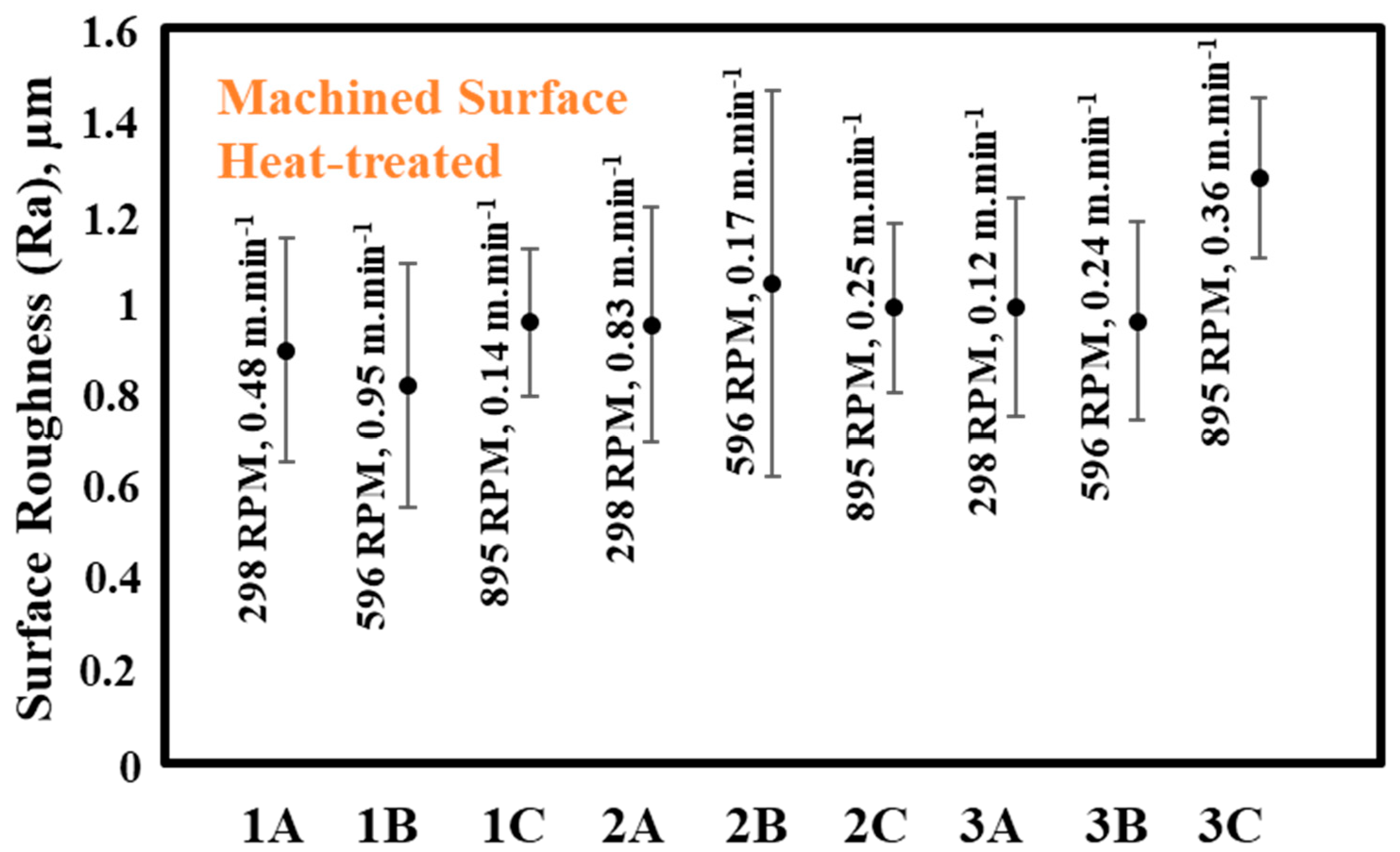
| Surface Roughness, Ra (µm) | |||||||||
|---|---|---|---|---|---|---|---|---|---|
| 1A | 1B | 1C | 2A | 2B | 2C | 3A | 3B | 3C | |
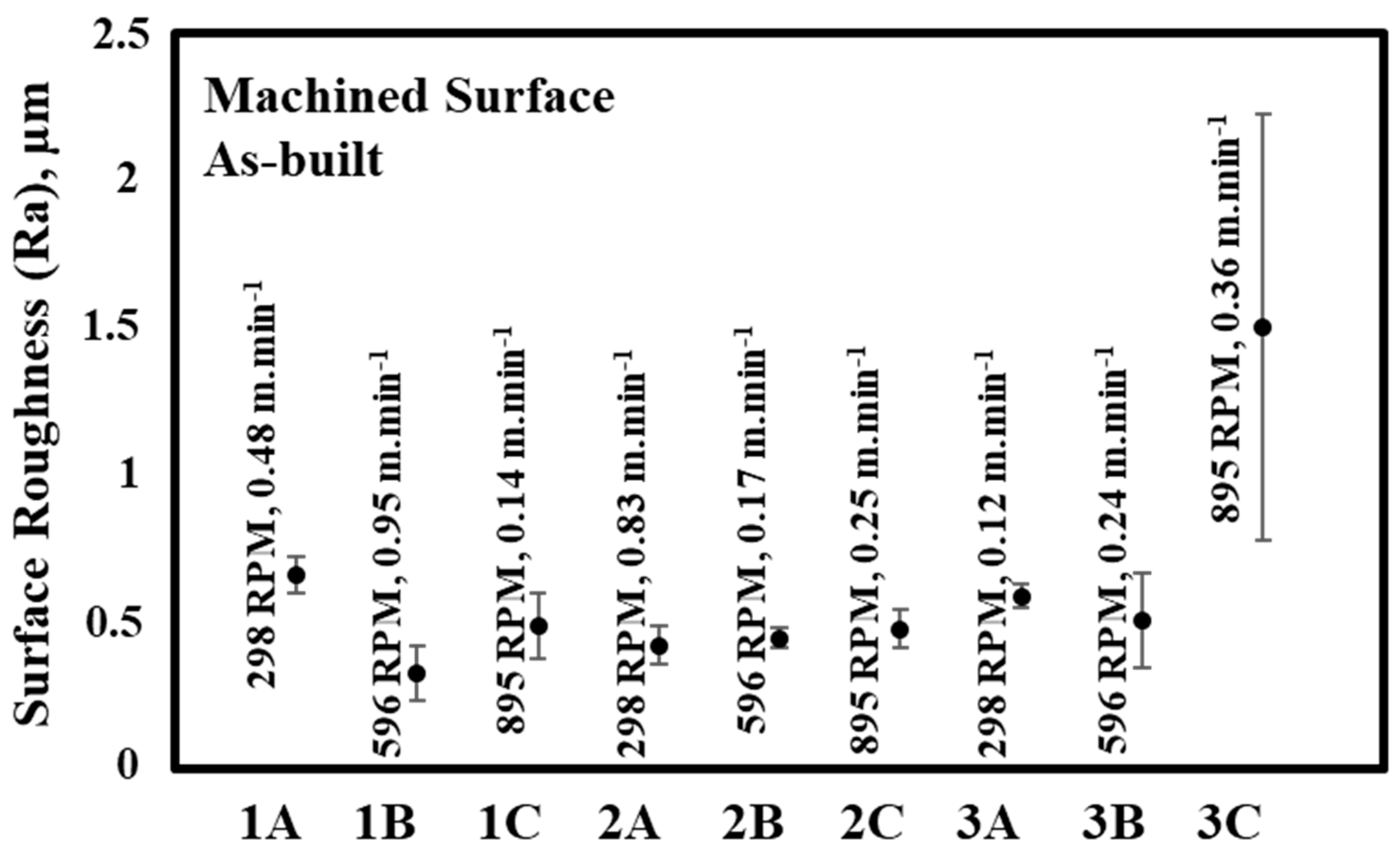
| As-built | 0.66 ± 0.1 | 0.33 ± 0.1 | 0.49 ± 0.1 | 0.42 ± 0.1 | 0.45 ± 0.05 | 0.48 ± 0.1 | 0.59 ± 0.05 | 0.51 ± 0.16 | 1.5 ± 0.7 |
| Heat-treated | 0.90 ± 0.24 | 0.82 ± 0.27 | 0.96 ± 0.2 | 0.96 ± 0.25 | 1.04 ± 0.42 | 0.99 ± 0.2 | 0.99 ± 0.24 | 0.96 ± 0.22 | 1.3 ± 0.2 |
| Hardness, HRC | |||||||||
|---|---|---|---|---|---|---|---|---|---|
| 1A | 1B | 1C | 2A | 2B | 2C | 3A | 3B | 3C | |
| As-built | 33.6 ± 3.2 | 34.1 ± 1.6 | 33.9 ± 0.9 | 33.2 ± 1.3 | 33.3 ± 0.9 | 33.8 ± 0.9 | 32.9 ± 1.3 | 32.7 ± 1.2 | 32.0 ± 2.6 |
| Heat-treated | 30 ± 1.1 | 30 ± 0.8 | 31.3 ± 0.9 | 31.4 ± 1.0 | 31.0 ± 0.9 | 31.1 ± 1.1 | 31.2 ± 1.9 | 31.4 ± 0.6 | 33.1 ± 1.1 |
Disclaimer/Publisher’s Note: The statements, opinions and data contained in all publications are solely those of the individual author(s) and contributor(s) and not of MDPI and/or the editor(s). MDPI and/or the editor(s) disclaim responsibility for any injury to people or property resulting from any ideas, methods, instructions or products referred to in the content. |
© 2023 by the authors. Licensee MDPI, Basel, Switzerland. This article is an open access article distributed under the terms and conditions of the Creative Commons Attribution (CC BY) license (https://creativecommons.org/licenses/by/4.0/).
Share and Cite
Isik, M.; Yildiz, M.; Secer, R.O.; Sen, C.; Bilgin, G.M.; Orhangul, A.; Akbulut, G.; Javidrad, H.; Koc, B. Fabrication of Electron Beam Melted Titanium Aluminide: The Effects of Machining Parameters and Heat Treatment on Surface Roughness and Hardness. Metals 2023, 13, 1952. https://doi.org/10.3390/met13121952
Isik M, Yildiz M, Secer RO, Sen C, Bilgin GM, Orhangul A, Akbulut G, Javidrad H, Koc B. Fabrication of Electron Beam Melted Titanium Aluminide: The Effects of Machining Parameters and Heat Treatment on Surface Roughness and Hardness. Metals. 2023; 13(12):1952. https://doi.org/10.3390/met13121952
Chicago/Turabian StyleIsik, Murat, Mehmet Yildiz, Ragip Orkun Secer, Ceren Sen, Guney Mert Bilgin, Akin Orhangul, Guray Akbulut, Hamidreza Javidrad, and Bahattin Koc. 2023. "Fabrication of Electron Beam Melted Titanium Aluminide: The Effects of Machining Parameters and Heat Treatment on Surface Roughness and Hardness" Metals 13, no. 12: 1952. https://doi.org/10.3390/met13121952
APA StyleIsik, M., Yildiz, M., Secer, R. O., Sen, C., Bilgin, G. M., Orhangul, A., Akbulut, G., Javidrad, H., & Koc, B. (2023). Fabrication of Electron Beam Melted Titanium Aluminide: The Effects of Machining Parameters and Heat Treatment on Surface Roughness and Hardness. Metals, 13(12), 1952. https://doi.org/10.3390/met13121952