Article

Microstructure and Superelasticity of Cu–Sn Shape-Memory Microwires by Glass-Coated Melt Spinning

1
State Key Laboratory for Advanced Metals and Materials, University of Science and Technology Beijing, Beijing 100083, China
2
i-Lab, Key Laboratory of Multifunctional Nanomaterials and Smart Systems, Suzhou Institute of Nano-Tech and Nano-Bionics (SINANO), Chinese Academy of Sciences (CAS), 398 Ruoshui Road, Suzhou 215123, China
*
Authors to whom correspondence should be addressed.
Metals 2023, 13(11), 1852; https://doi.org/10.3390/met13111852
Submission received: 19 July 2023 / Revised: 28 October 2023 / Accepted: 29 October 2023 / Published: 5 November 2023
(This article belongs to the Section Entropic Alloys and Meta-Metals)

Abstract

:
Cu–Sn shape-memory microw ires were fabricated by a glass-coated melt spinning method. Effects of Sn content on the microstructure and mechanical properties of microwires were investigated. The phase transforms from martensite to austenite with an increase in Sn from 14.0 atomic percent (at.%) to 16.5 at.%. When the Sn content exceeds 16.5 at.%, a highly ordered intermetallic phase, δ, formed. The fracture stress (σf) and the critical stress for martensitic transformation (σMs) increases with an increase in Sn content. The mechanical properties as well as the superelasticity were greatly improved by a high cooling rate in the glass-coated melt spinning method. A bamboo-grained structure was formed in the Cu–Sn microwire with a Sn content of 16 at.% by annealing at 750 °C for 5 h before quenching in water. The results indicate that two opposite strategies of refining the grain size to the micrometer level, or increasing the grain size to a one dimensional size of specimen, e.g., the diameter of the wire, are both effective in improving the superelasticity of the Cu–Sn alloy.

1. Introduction

Shape memory alloys (SMAs) are a unique class of functional material that exhibit shape recovery upon heating, as well as superelasticity upon loading. Both of these properties result from a reversible solid state phase transformation, called thermoelastic martensite transformation. Many shape memory alloys [1,2,3,4,5] have been used for specialized commercial applications and have shown great potential in emerging fields, such as elastocaloric solid-state refrigerators [6,7,8] or flexible electronics [9,10]. Within the most important SMA systems, Cu-based shape-memory alloys are of particular interest because of their large range of transformation temperatures and high electrical conductivity [11]. Single crystals of these Cu-based SMAs exhibit excellent shape-memory and superelastic effects [12,13]. However, due to the stress concentration or incompatibility at the grain boundary and the triple junction, the bulk polycrystals of Cu-based SMAs usually undergo brittle intergranular fracture during deformation [14,15], which severely prevents their widespread application.
Two opposite strategies were applied to improve the mechanical properties of Cu-based SMAs: increasing the grain size as large as possible or refining the grain size to the micrometer range. The first strategy aims to improve deformation compatibility by reducing the total grain boundary area and removing triple junctions. The development of bamboo-like grained (BLG) Cu-based SMAs is a typical representative. Omori et al. [16,17] prepared BLG Cu–Al–Mn SMAs by a cyclic heat treatment process. Schuh et al. [18,19,20] produced BLG Cu–Al–Ni and Cu–Zn–Al SMA microwires with superelasticity of over 7%. Another strategy attempts to suppress intergranular fracture by refining the grain size. For example, Font et al. [21] reported Cu–Al–Ni-based ribbon by a single roll melt-spinning technique. Ochin et al. [22] reported Cu–Al–Ni wire fabricated by an in-rotating-water spinning method. However, mechanical properties of such ribbon and wire were not greatly improved, because the grain size was still at the scale of tens of micrometers.
Amongst the Cu-based SMAs, the Cu–Sn system has been least investigated, possibly due to the poor shape-memory and superelastic effect of bulk polycrystals [23,24,25,26]. Li et al. [25] reported a good shape memory effect of rapidly quenched ribbons of Cu–Sn polycrystalline alloys with a grain size of about 1.5 µm. However, the superelastic effect was not further investigated in these ribbons. In the present study, Cu–Sn microwires with a diameter of 10–200 µm were prepared by a glass-coated melt spinning method. Due to the rapid cooling rate, the grain size of the as-cast microwires was refined down to the micrometer scale. Significant superelastic effects were found in these microwires, and the effects of Sn content on the microstructure and superelastic behavior of Cu–Sn microwires were investigated systematically. Interestingly, by annealing at 750 °C for 5 h before quenching in water, a bamboo-like grain structure was obtained in the Cu–Sn microwire, which also shows excellent superelasticity. The results indicate that the two opposite strategies of refining the grain size to the micrometer level or increasing the grain size to a one dimensional size of specimen, e.g., the diameter of the wire, are both effective for improving superelasticity of the Cu–Sn alloy. The superelastic Cu–Sn microwires could possibly be used in many application scenarios, such as developing passive damping systems based on superelastic microwires, manufacturing composites for vibration reduction in building materials, and developing low-cost medical guidewires, as it could be produced in large quantities via the continuous glass-coated melt spinning process.

2. Experimental

Cu–Sn ingots with variable Sn content were prepared by inductively melting the mixture of highly pure Cu and Sn (>99.9%) in a quartz glass tube under an argon atmosphere. They were named A1–A6, and their atomic composition is given in Table 1. Microwires with different compositions were fabricated by rapid solidification using a glass-coated melt spinning method [27,28]. The schematic illustration and actual facility of the glass-coated melt spinning is shown in Figure 1. Firstly, the ingot was cut into small pieces of approximately 1–2 g, which was placed into a Pyrex glass tube. Then we placed the bottom of the glass tube in a high-frequency induction heater and introduced argon gas from the top of the glass tube. Afterwards, the alloy was heated to the melting point through the inductor heater, and formed a droplet. When the alloy melted, the bottom of the glass tube adjacent to the molten alloy softened and surrounded the droplet. When we used a glass rod with an ultra-fine tip to contact the bottom of the glass tube and pulled the glass bar, a glass capillary with molten alloy as its core was drawn down. The molten alloy solidified rapidly through water cooling. Therefore, a microwire was formed with metal core completely covered by a glass shell. The microwire was wound around a receiving coil, and the rotational speed determined the wire diameter and glass thickness.
In order to investigate the influence of grain size on the superelastic properties, we annealed the glass-coated microwires with different diameters at 750 °C for 5 h, and then quenched them in water. Finally, the glassy cover was carefully removed. The surface morphology was examined by scanning electron microscopy (SEM). In order to observe the microstructure, the longitudinal section of wires were polished and then etched by a solution of 5 g (FeCl3) + 15 mL (HCl) + 100 mL (C2H5OH) [29]. Pieces of wire were closely arrayed on a glass slide, and the structure was examined by X-ray diffraction (XRD) with Cu Kα radiation. For transmission electron microscopy (TEM), several microwires approximately 10 mm in length were stuck tightly, side by side, onto a hollow copper ring, and then the exposed wires outside the copper ring were cut off. Finally, ion thinning was performed to prepare the TEM sample. Tensile testing of microwires was performed using a Micro-Tester, and the loading–unloading tensile test was performed to study the superelastic effect. The wires were bonded to a specially designed paper frame with Aron-Alpha adhesive. All the tensile testing was performed at room temperature.

3. Results

3.1. Effect of Sn Content on the Phase Composition and Microstructure of Cu–Sn Microwires

Figure 2 shows SEM images of the surface morphology of microwires with different compositions. As shown in Figure 2a, martensites, which are close to each other and go through the cross section, could be seen clearly on the surface of A1. Figure 2b shows that some banded martensites, which are not as dense as A1, go through the cross section of A2. Figure 2c–f correspond to A3, A4, A5 and A6, respectively. It is clear that the wires are almost flawless and precisely circular. The length of microwires could reach up to hundreds of meters, implying that the glass-coated melt spinning method is a very effective technique to produce high-quality Cu–Sn microwires.
Microstructure of the longitudinal cross-section of A1 is shown in Figure 3a,b. A large number of wedge-shaped martensites with different widths go through the cross-section of the microwire, and the amount of lamellar martensites could also be observed. Sparse banded martensites, which have different micrograph compared with A1, could be seen in the longitudinal cross-section of A2 as shown in Figure 3c,d. The longitudinal cross-section of A3 is shown in Figure 3e,f. There is no martensite, and a large number of submicron grains can be seen. During the glass-coated spinning process, when the microwires pass through the cooling water, the surface glass will be cooled rapidly, and the alloy liquid in contact with the coated glass will be under strong supercooling, resulting in the simultaneous formation of a large number of crystal nuclei. Because of the extremely small microwire size, the cooling rate is very large, and the grains have neither space nor time to grow into dendrites. As a result, the grain size of the as-cast Cu–Sn microwires was refined to the micrometer scale.
Figure 4 shows X-ray diffraction patterns of microwires with different compositions. All identified peaks of A3 and A4 are indexed with a BCC cubic structure of the austenite phase, while all peaks of A1 are indexed with martensite. For A2 microwire, the phase is mainly austenite, with partial β1′ martensite as indicated by diffraction peaks from 29° to 42° [30]. The XRD pattern of A6 presents a complex structure of highly ordered intermetallic δ phase. The results show that the phase transforms from martensite to austenite with the increase in Sn from 14.0 atomic percent (at.%) to 16.5 at.%. When the Sn content exceeds 16.5 at.%, a highly ordered intermetallic phase, δ, formed. The results are consistent with morphology and microstructure observation by SEM.
Saunders et al. [31] summarized martensite structures formed by water quenching from high-temperature β or γ solid phases in the Cu–Sn alloy system. With the increase in Sn content, three types of martensite structure are usually observed: β1′, β1″, and γ1′. The β1′ (18R) martensite has an ordered orthorhombic structure and is found between 13 and 13.8 at.% Sn. β1″ (18R/2H) martensite, found between 13.8 and 15 at.% Sn, is a lamellar composite of orthorhombic β1′ and hexagonal γ1′ martensites. The γ1′ martensite, formed between 15 and 15.8 at.% Sn, is a twinned cph structure. The β1′ and β1″ martensites formed by water quenching from the high-temperature β phase to room temperature. The γ1′ martensite was formed by two steps [32]. Firstly, the high-temperature β phase transformed to β1 phase with an ordered D03 structure by water quenching, and then this ordered β1 phase transformed to γ1′ martensite by the following cooling to −196 °C in liquid nitrogen.
For the as-cast A1 and A2 microwires, the martensite structure shows the martensitic transformation temperature is above room temperature, and the phase may be β1′ martensite in A1 and A2. With Sn content higher than 15 at.%, the martensitic transformation temperature is lower than the room temperature, so the phase of the as-cast A3 and A4 is austenite. When the Sn content reaches up to 17.5 at.%, some highly ordered intermetallic phase δ formed in A5. For A6, the δ phase becomes the main phase. It means the eutectic transformation was not suppressed even by rapid cooling from melting when Sn content reaches above 17.5 at.%. The δ phase was also reported to form by quenching Cu-18.5 at.% Sn alloy into water after annealing at 700 °C [33].
Figure 5a,b show TEM micrographs of the as-cast A1 microwire. Complicated microstructure, containing wedge-shaped martensite is shown in Figure 5a, and many are nanocrystalline with a size of about 5 nm in the HRTEM image as shown in Figure 5b. The morphology of the martensite in the as-cast A2 microwire is shown in Figure 5c. It is similar to the banded β1′ martensite reported in the literature [34,35]. Moreover, the micro-twin structure of martensites could be observed. The corresponding selected-area electron diffraction (SAED) pattern is shown in Figure 5d, it presents three sets of diffraction spots, namely β1 with a D03 structure and mutual twins of martensitic variants.

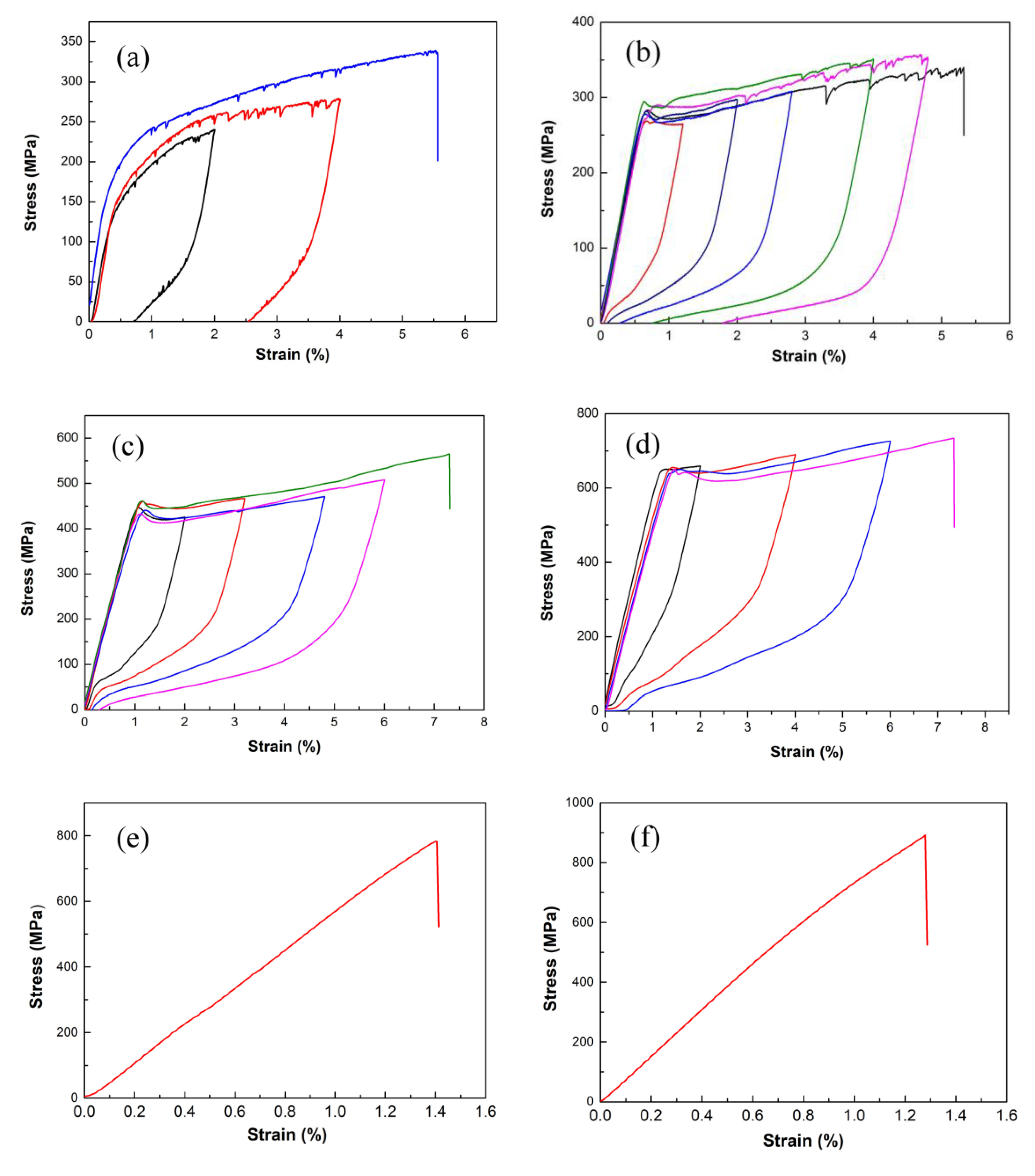
3.2. Effect of Sn Content on the Superelasticity of Cu–Sn Microwires

Figure 6 shows stress–strain curves of microwires with a diameter of 40–60 µm. The gauge length is fixed at 25 mm, and the strain rate is 1.33 × 10⁻³s−1. It shows that partial strain recovered after unloading for A1 and A2, while nearly the total strain recovered for A3 and A4. The stress–strain curves of A3 and A4 show a typical superelastic effect, exhibiting a reversible strain of several percent. This superelasticity relies on the occurrence of a thermoelastic martensitic transformation by a combination of transformation of stress-induced martensitic transformation upon loading and its reverse transformation upon unloading [36,37,38]. It is different from the stress–strain curve with two plateaus in Cu–Sn bulk single crystals [39], which are associated with the successive martensitic transformation, as there is only one plateau on the stress–strain curve for all superelastic microwires. The microwires fractured only after elastic deformation of A5 and A6, due to the highly ordered brittle δ phase.
It is interesting that serration behavior appeared immediately after yield on the stress–strain curve of A1 microwire, which also appeared during unloading, while for A2 microwire, serration behavior happened after yield with strain greater than 2% upon loading, and it did not appear during unloading. No serration flow appeared for A3 and A4. Serration phenomenon was also reported in other materials [40]. This serration behavior may be related to the accumulated formation of micro-twins of martensite during loading, which was also observed in stress–strain curves of Cu–Al wires produced by a horizontal in-rotating-liquid-spinning method [40].
Figure 7 shows the relationship between the recovery ratio and the total strain. The recovery ratio of A1 is minimal. It decreases rapidly with total strain increasing for A2, while it does not change remarkably for A3 and A4. When the total strain is 6%, the recovery ratios for A3 and A4 reach up to 95% and 92%, respectively. These results are in accordance with the microstructure, as only the austenite phase has a superelastic effect. A1 mainly contains martensite, so little superelastic effect was observed. A2 shows partial superelastic recovery as it is a mixture of austenite and martensite. A3 and A4 mainly contains austenite, which results in a significant superelastic effect.
Different to reported experiments related to the martensitic transformation in the Cu–Sn system [32,41], where bulk specimens are always quenched from a high-temperature β or γ solid phase, Cu–Sn microwires were directly prepared from the melt by rapid solidification using the method of glass-coated melt spinning in this work. The mechanical and superelastic effects for A3 and A4 were greatly improved, due to the high cooling rate, which suppressed precipitation of unwanted equilibrium phases and refined grains to the micrometer or sub-micrometer scale.
The Sn content dependence of the fracture stress is shown in Figure 8a. It is clear that the fracture stress, σf, increases when Sn content increases. Figure 8b shows the critical stress for martensitic transformation, σMs, which corresponds to an effective yield stress in superelastic behavior, and increases when Sn content increases. The martensitic transition temperature in Cu–Sn alloy decreases with the increase in Sn content [32], and is lower than room temperature when the Sn content is higher than 15 at.%. The higher the Sn content, the farther the transformation temperature is from room temperature, so the more stable the austenite phase is at room temperature, resulting in higher critical stress for stress-induced martensitic transformation. The relationship between the critical stress for stress-induced martensitic transformation, σMs, and the temperature, T, is usually in agreement with the Clausius–Clapeyron relation [38] for a certain component of shape memory alloy:
d σ = Δ S ε v m · d T
where ∆S is the molar entropy difference between the parent and martensite phases, ε is the strain caused by the phase transformation, and vm is the molar volume. Since σMs equals zero at the martensitic transformation start temperature, the relationship could be described as σMs = Δ S ε v m · Δ T , where Δ T is the temperature difference between the test temperature and Ms. In this study, the test temperature is room temperature. As Ms decreases with Sn content increasing, Δ T will increase, resulting in higher critical stress for stress-induced martensitic transformation.

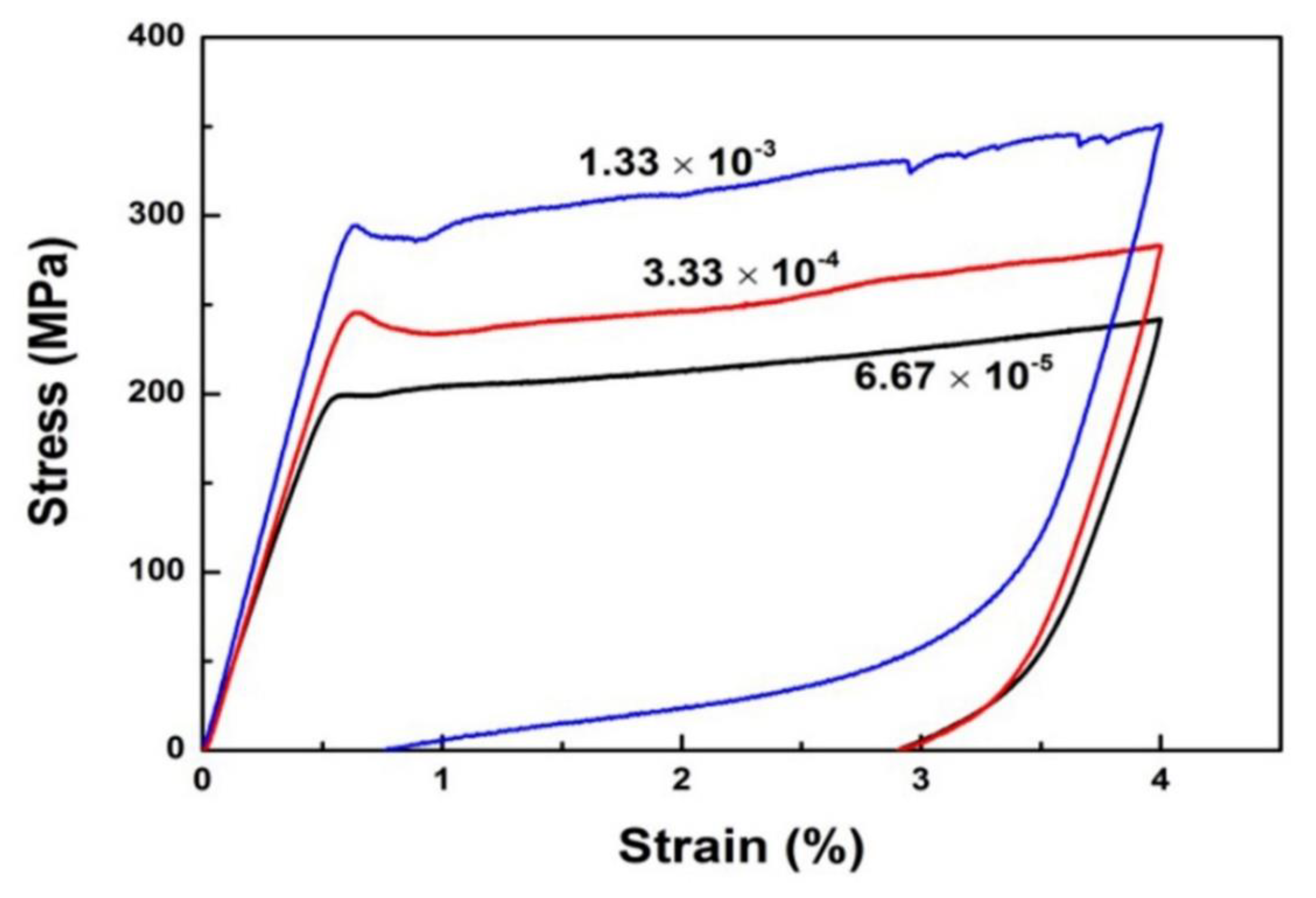
3.3. Effect of Strain Rate on the Superelasticity of Cu–Sn Microwires

The tensile stress–strain curves at various strain rates for A2 microwire are shown in Figure 9. The residual strains at strain rates of 6.67 × 10⁻⁵, 3.33 × 10⁻⁴ and 1.33 × 10⁻³ are 2.91%, 2.91% and 0.75%, respectively. It shows that as the strain rate increases, the superelastic effect becomes more significant. The critical stress for martensitic transformations, σMs, increases when strain rate increases. This phenomenon was also reported in Cu-15.0 at.% Sn single crystals [42].
The shape memory effect and superelasticity are characterized by the reversible motion of an interface between the austenite and martensite. The origin of the strain rate dependence could be attributed to the thermally activated motion of the interface. Kato [42] thought that when the velocity of an interface is slow, Sn atoms would be trapped at the interface through the interaction between them, and the mobility of an interface will decrease. It implies that the higher the strain rate, the easier it is for the interface to move, and the more superelastic the stress–strain behavior becomes.

3.4. Superelastic Effect of Bamboo-like Grain Structured Cu–Sn Microwires

In Cu-based SMAs, the grain size has a great influence on the superelastic properties. Sutou [43,44] found that with the increase in grain size, the recoverable strain gradually increased in Cu–Al–Mn shape memory alloy wires and sheets. Ueland [18,19] obtained bamboo-like grained Cu–Al–Ni and Cu–Zn–Al microfibers with great superelastic and two-way shape memory effects. Schuh [19] referred to this type of microfiber with a bamboo-like structure as an oligocrystalline shape memory alloy. Here, a bamboo-like grain structure was obtained in microwires with Sn content of 16 at.% (A3) via heat treatment by annealing at 750 °C for 5 h before quenching in water. Figure 10 shows SEM images of the surface morphology of microwires with different diameters. It can be seen that the grains of microwire with a diameter of 56 µm span the entire cross-section of the wire, presenting a typical bamboo-like structure, while on the surface of the microwire with a diameter of 179 µm, several triple junctions could be observed, with grain size smaller than the diameter of the microwire.
According to the Cu–Sn phase diagram [31,33], the equilibrium phase of the Cu–Sn alloy with Sn content of 16 at.% is a disordered β phase at 750 °C, which would transform to a β1 phase with an ordered D03 structure by the following water quenching. At room temperature, stress-induced martensitic transformation would happen in the ordered β1 phase. The loading–unloading stress–strain curves of the microwires with diameter of 56 μm and 179 μm are shown in Figure 11. It shows that after unloading from 3.2% strain, the residual strain of the 56 μm diameter microwire is 0.11%, while that of the 179 μm diameter microwire is 0.57%. The results indicate the 56 μm diameter microwire with bamboo-like structure has better superelasticity than the 179 μm diameter microwire with triple junctions. This is consistent with the results observed in other Cu-based shape memory alloy wires and sheets [18,19,43,44].

4. Discussion

The above experimental results indicate that the superelastic effect of Cu–Sn microwires does not change monotonically with the grain size. When the grain size of the glass-coated microwires prepared by water cooling is refined to the micrometer level, the alloy has good mechanical and superelastic properties. When the grain of the microwire grows to be equivalent to the one-dimensional size of the specimen after annealing, the mechanical properties could also be improved. However, when the grain size is between the two rules, the superelastic properties decay. Notably, although Schuh et al. [18,19] have concluded that bamboo-like structures have better mechanical and superelastic properties than coarse-grained polycrystals in Cu–Zn–Al microfibers, they have not reported microfibers with ultrafine grains. This is because they used the most traditional Taylor method to make microfibers, without the use of a water-cooling device to rapidly cool the microfiber.
In this work, for the A3 (Cu84Sn16) composition, the Cu–Sn microwires are in austenitic state at room temperature, and there are two competing deformation mechanisms under applied stress, namely, irreversible dislocation slips and reversible stress-induced martensitic phase transition. The grain size of Cu–Sn microwires prepared by the glass coating method has been refined to the micrometer level, thereby improving their grain boundary strength. During the transformation into martensite under applied stress, the strain is dispersed by the amount of small grains, so the stress concentration at the grain boundary is negligible, and the strain can be coordinated among grains. Therefore, the fracture strength of Cu–Sn microwires prepared by water cooling is improved, and the microwires show excellent superelastic properties.
With the grain size increasing, the coarse grains form triple junctions with each other. Under an applied external force, martensite variants formed with the same orientation in coarse grains with different crystal orientations. Due to the limitation of grain boundaries, it is difficult to coordinate the strains of adjacent grains, so it results in great stress concentration at the triple junctions and seriously deteriorates superelasticity. When the grain size increases to match the one-dimensional size of the specimen, bamboo-grained microwires formed where triple junctions are eliminated and grain boundaries are sparse. In these microwires, the surface area is larger than the total grain boundary area, meaning that grains are coordinated mostly by unconfined free surfaces rather than rigid boundaries. Due to the reduction in grain boundary restriction in space, the free surface can effectively relieve the transformation stresses and reduce the transformation incompatibilities. As a result, each individual grain can undergo transformation like a single crystal and show excellent superelasticity.
In the present study, by controlling the process conditions, we obtained Cu–Sn microwires with different grain sizes from ultrafine grains by rapid cooling to bamboo-like grains by heat annealing. The relationship between superelasticity and grain size was studied, which indicates that two opposite strategies of refining the grain size to the micrometer level or increasing the grain size to the one dimensional size of the specimen, e.g., the diameter of the wire, are both effective to improve superelasticity of the Cu–Sn alloy.

5. Conclusions

To summarize, Cu–Sn shape-memory microwires were fabricated by a glass-coated melt spinning method. Effects of Sn content on the microstructure and mechanical properties of Cu–Sn microwires were investigated, and the relationship between superelasticity and grain size was studied. The main findings can be summarized as follows:
(1)
Cu–Sn microwires with a diameter of 10–200 µm were fabricated successfully by the glass-coated melt spinning method. For the high cooling rate, the grain size of as-cast Cu–Sn microwires could be refined to the scale of micrometers. The phase in the as-cast microwires gradually transforms from martensite to austenite with Sn content increasing from 14.0 at.% to 16.5 at.%. When the Sn content exceeds 16.5 at.%, a highly ordered intermetallic phase, δ, is formed.
(2)
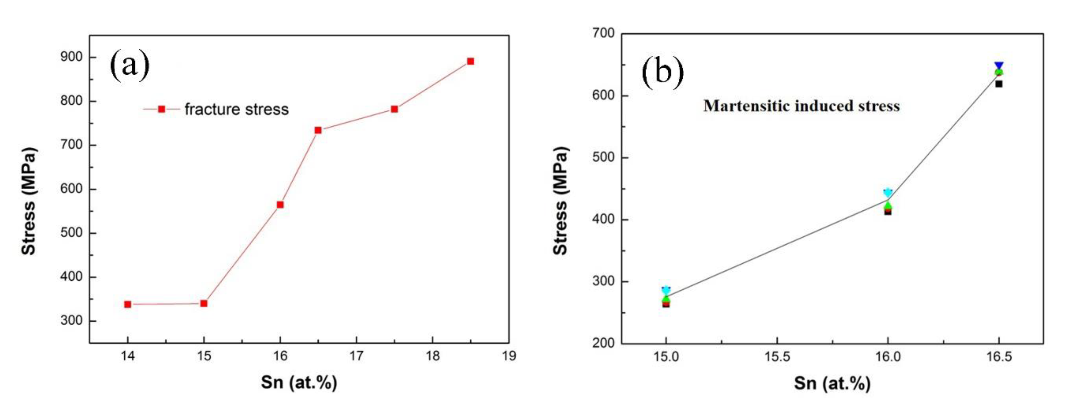
Microwires with Sn content of 16 at.% (A3) and 16.5 at.% (A4) show excellent superelasticity. The fracture stress, σf, and the critical stress for stress-induced martensitic transformation, σMs, increases with Sn content increases. Strain rate has a significant influence on the superelasticity of microwires. The higher the strain rate, the better the superelasticity of the microwires.
(3)
A bamboo-grained structure was formed in the Cu–Sn microwire with a Sn content of 16 at.% (A3) by annealing at 750 °C for 5 h before quenching in water. Due to the unconfined free surfaces and absence of triple junctions, the bamboo-like grain structure also shows excellent superelasticity. The results show that two opposite strategies of refining the grain size to the micrometer level or increasing the grain size to the one dimensional size of the specimen are both effective in improving the superelasticity of the Cu–Sn alloy.

Author Contributions

Conceptualization, Y.Z. (Yangyong Zhao) and Y.Z. (Yong Zhang); methodology, Y.Z. (Yangyong Zhao); formal analysis, Y.Z. (Yangyong Zhao), Y.B. and T.L.; writing—original draft preparation, Y.Z. (Yangyong Zhao), Y.B. and T.L.; writing—review and editing, Y.Z. (Yong Zhang); All authors have read and agreed to the published version of the manuscript.

Funding

This research was funded by the Natural Science Foundation of Jiangsu Province (BK20200259), the National Natural Science Foundation of China (52273280), the Jiangxi Provincial Natural Science Foundation (20224ACB212001), the Youth Promotion Association of Chinese Academy of Sciences (2020320), and the Creative Research Groups of China (No. 51921001).

Data Availability Statement

Data is available from corresponding author on reasonable request.

Conflicts of Interest

The authors declare that they have no conflicts of interest.

References

  1. Ölander, A. An electrochemical inverstigation of solid cadmium-gold alloys. J. Am. Chem. Soc. 1932, 56, 3819–3833. [Google Scholar] [CrossRef]
  2. Otsuka, K.; Ren, X. Physical metallurgy of Ti-Ni-based shape memory alloys. Prog. Mater. Sci. 2005, 50, 511–678. [Google Scholar] [CrossRef]
  3. Chluba, C.; Ge, W.W.; Miranda, R.L.; Strobel, J.; Kienle, L.; Quandt, E.; Wuttig, M. Ultralow-fatigue shape memory alloy films. Science 2015, 348, 1004–1107. [Google Scholar] [CrossRef] [PubMed]
  4. Kainuma, R.; Imana, Y.; Ito, W.; Sutou, Y.; Morito, H.; Okamoto, S.; Kitakami, O.; Oikawa, K.; Fujita, A.; Kanomata, T.; et al. Magnetic-field-induced shape recovery by reverse phase transformation. Nature 2006, 439, 957–960. [Google Scholar] [CrossRef] [PubMed]
  5. Ogawa, Y.; Ando, D.; Sutou, Y.; Koike, J. A lightweight shape-memory magnesium alloy. Science 2016, 353, 368–370. [Google Scholar] [CrossRef] [PubMed]
  6. Hou, H.; Simsek, E.; Ma, T.; Johnson, N.S.; Qian, S.; Cissé, C.; Stasak, D.; Al Hasan, N.; Zhou, L.; Hwang, Y.; et al. Fatigue-resistant high-performance elastocaloric materials made by additive manufacturing. Science 2019, 366, 1116–1121. [Google Scholar] [CrossRef] [PubMed]
  7. Qian, S.; Catalini, D.; Muehlbauer, J.; Liu, B.; Mevada, H.; Hou, H.; Hwang, Y.; Radermacher, R.; Takeuchi, I. High-performance multimode elastocaloric cooling system. Science 2023, 380, 722–727. [Google Scholar] [CrossRef] [PubMed]
  8. Wang, R.; Fang, S.; Xiao, Y.; Gao, E.; Jiang, N.; Li, Y.; Mou, L.; Shen, Y.; Zhao, W.; Li, S.; et al. Torsional refrigeration by twisted, coiled, and supercoiled fibers. Science 2019, 366, 216–221. [Google Scholar] [CrossRef]
  9. Zhao, Y.; Zhou, W.; Shi, Y.; Yang, X.; Bai, Y.; Li, L.; Wang, S.; Li, T.; Feng, S.; Zhang, T. Superelastic alloy based electrical interconnects for highly stretchable electronics. Npj Flex. Electron. 2022, 6, 8. [Google Scholar] [CrossRef]
  10. Curtis, S.M.; Gugat, J.L.; Bumke, L.; Duygu, D.; Seigner, L.; Schmadel, D.; Lazarus, N.S.; Quandt, E. Thin-film superelastic alloys for stretchable electronics. Shape Mem. Superelast. 2023, 9, 35–49. [Google Scholar] [CrossRef]
  11. Lovey, F.C.; Torra, V. Shape memory in Cu-based alloys: Phenomenological behavior at the mesoscale level and interaction of martensitic transformation with structural defects in Cu-Zn-Al. Prog. Mater. Sci. 1999, 44, 189–289. [Google Scholar] [CrossRef]
  12. Shimizu, K.; Otsuka, K.; Wayman, C.M.; Nakai, K.; Sakamoto, H. Superelasticity effects and stress-induced martensitic transformation in Cu-Al-Ni alloys. Acta Metall. 1976, 24, 207–226. [Google Scholar]
  13. Qiao, L.; Rimoli, J.J.; Chen, Y.; Schuh, C.A.; Radovitzky, R. Nonlocal superelastic model of size-dependent hardening and dissipation in single crystal Cu-Al-Ni shape memory alloys. Phys. Rev. Lett. 2011, 106, 085504. [Google Scholar] [CrossRef] [PubMed]
  14. Horikawa, H.; Ichinose, S.; Morii, K.; Miyazaki, S.; Otsuka, K. Orientation dependence of β1β1′ stress-induced martensitic transformation in a Cu-Al-Ni alloy. Metall. Trans. A 1988, 19A, 915–923. [Google Scholar] [CrossRef]
  15. Miyazaki, S.; Kawai, T.; Otsuka, K. On the origin of intergranular fracture in β phase shape memory alloys. Scr. Metall. 1982, 16, 431–436. [Google Scholar] [CrossRef]
  16. Omori, T.; Kusama, T.; Kawata, S.; Ohnuma, I.; Sutou, Y.; Araki, Y.; Ishida, K.; Kainuma, R. Abnormal grain growth induced by cyclic heat treatment. Science 2013, 341, 1500–1502. [Google Scholar] [CrossRef] [PubMed]
  17. Kusama, T.; Omori, T.; Saito, T.; Kise, S.; Tanaka, T.; Araki, Y.; Kainuma, R. Ultra-large single crystals by abnormal grain growth. Nat. Commun. 2017, 8, 1–9. [Google Scholar] [CrossRef]
  18. Ueland, S.M.; Schuh, C.A. Superelasticity and fatigue in oligocrystalline shape memory alloy microwires. Acta Mater. 2012, 60, 282–292. [Google Scholar] [CrossRef]
  19. Ueland, S.M.; Chen, Y.; Schuh, C.A. Oligocrystalline Shape memory alloys. Adv. Funct. Mater. 2012, 22, 2094–2099. [Google Scholar] [CrossRef]
  20. Tuncer, N.; Schuh, C.A. Melt-cast microfibers of Cu-based shape memory alloy adopt a favorable texture for superelasticity. Scr. Mater. 2016, 117, 46–50. [Google Scholar] [CrossRef]
  21. Font, J.; Cesari, E.; Muntasell, J.; Pons, J. Thermomechanical cycling in Cu-Al-Ni-based melt-spun shape-memory ribbons. Mater. Sci. Eng. A 2003, 354, 207–211. [Google Scholar] [CrossRef]
  22. Ochin, P.; Dezellus, A.; Plaindoux, P.; Pons, J.; Vermaut, P.; Portier, R.; Cesari, E. Shape memory thin round wires produced by the in rotating water melt-spinning technique. Acta Mater. 2006, 54, 1877–1885. [Google Scholar] [CrossRef]
  23. Ceylan, M.; Zengin, R. Shape memory properties and oxidation behaviour of a rapidly liquid quenched Cu–Sn alloy. J. Mater. Process Tech. 2000, 97, 148–152. [Google Scholar] [CrossRef]
  24. Kamal, M. Mechanical properties of rapidly solidified of Cu-Sn shape memory alloys. Radiat. Eff. Defects Solids 2006, 161, 189–191. [Google Scholar] [CrossRef]
  25. Li, D.S.; Rong, Q.G.; Zhu, Y. The shape memory effect (SME) of liquid rapidly quenched (LRQ) Cu-Sn alloys. In Rapidly Quenched Metals; Elsevier Science Publishers B.V.: North-Holland, the Netherlands, 1985; pp. 1425–1428. [Google Scholar]
  26. Zhao, Y.Y.; Li, H.; Wang, Y.S.; Zhang, Y.; Liaw, P.K. Shape memory and superelasticity in amorphous/nanocrystalline Cu-15.0 atomic percent (at.%) Sn wires. Adv. Eng. Mater. 2014, 16, 40–44. [Google Scholar] [CrossRef]
  27. Zhao, Y.Y.; Li, H.; Hao, H.Y.; Li, M.; Zhang, Y.; Liaw, P.K. Microwires fabricated by glass-coated melt spinning. Rev. Sci. Instrum. 2013, 84, 075102. [Google Scholar] [CrossRef] [PubMed]
  28. Larin, V.S.; Torcunov, A.V.; Zhukov, A.; González, J.; Vazquez, M.; Panina, L. Preparation and properties of glass-coated microwires. J. Magn. Magn. Mater. 2002, 249, 39–45. [Google Scholar] [CrossRef]
  29. Yang, Y.; Xu, J.F.; Zhai, Q. Rapid dendritiv growth in melt-spun Cu-Sn alloys. Chin. J. Nonferrous Met. 2007, 17, 1521–1526. [Google Scholar]
  30. Bondt, M.D.; Deruyttere, A. Pearlite and bainite formation in a Cu-16.5 at.% Sn alloy. Acta Metall. 1967, 15, 993–1005. [Google Scholar] [CrossRef]
  31. Saunders, N.; Miodownlk, A.P. The Cu-Sn (Copper-Tin) System. Bull. Alloy Phase Diagr. 1990, 11, 279–285. [Google Scholar] [CrossRef]
  32. Kennon, N.F.; Miller, T.M. Martensitic transformations in β1 Cu-Sn alloy. Trans. JIM 1972, 13, 322–326. [Google Scholar] [CrossRef]
  33. Fürtauer, S.; Li, D.; Cupid, D.; Flandorfer, H. The Cu-Sn phase diagram, Part I: New experimental results. Intermetallics 2013, 34, 142–147. [Google Scholar] [CrossRef] [PubMed]
  34. Shimizu, K.I.; Sakamoto, H.; Otsuka, K. On the crystal structure of the banded martensite in Cu-24.5 wt% Sn alloy. Trans. JIM 1975, 16, 581–590. [Google Scholar] [CrossRef]
  35. Kuwano, N.; Wayman, C.M. Precipitation Processes in a β-Phase Cu-15 at.% Sn Shape Memory Alloy. Trans. JIM 1983, 24, 499–503. [Google Scholar] [CrossRef]
  36. Jani, J.M.; Leary, M.A. Subic and M.A. Gibson. A review of shape memory alloy research, applications and opportunities. Mater. Design 2014, 56, 1078–1113. [Google Scholar] [CrossRef]
  37. Juan, J.M.S.; Nό, M.L.; Schuh, C.A. Superelasticity and shape memory in micro- and nanometer-scale pillars. Adv. Mater. 2008, 20, 272–278. [Google Scholar] [CrossRef]
  38. Omori, T.; Ando, K.; Okano, M.; Xu, X.; Tanaka, Y.; Ohnuma, I.; Kainuma, R.; Ishida, K. Superelastic effect in polycrystalline ferrous alloys. Science 2011, 333, 68–71. [Google Scholar] [CrossRef]
  39. Kato, H.; Miura, S. Thermodynamical analysis of the stress-induced martensitic transformation in Cu-15.0 at.% Sn alloy single crystals. Acta Metall. Mater. 1995, 43, 351–360. [Google Scholar] [CrossRef]
  40. Zeller, S.; Gnauk, J. Shape memory behavior of Cu-Al wires produced by horizontal in-rotating-liquid-spinning. Mater. Sci. Eng. A 2008, 481–482, 562–566. [Google Scholar] [CrossRef]
  41. Miura, S.; Morita, Y.; Nakanishi, N. Superplasticity and Shape Memory Effect in Cu-Sn Alloys. In Shape Memory Effect in Alloys; Perkins, J., Ed.; Plenum Press: New York, NY, USA, 1976; pp. 389–405. [Google Scholar]
  42. Kato, H.; Hirata, N.; Miura, S. Effects of aging on pseudoelastic behaviour in Cu-15.0 at.% Sn alloy single crystals. Acta Metall. 1995, 43, 361–369. [Google Scholar] [CrossRef]
  43. Sutou, Y.; Omori, T.; Yamauchi, K.; Ono, N.; Kainuma, R.; Ishida, K. Effect of grain size and texture on pseudoelasticity in Cu-Al-Mn-based shape memory wire. Acta Mater. 2005, 53, 4121–4133. [Google Scholar] [CrossRef]
  44. Sutou, Y.; Omori, T.; Kainuma, R.; Ishida, K. Grain size dependence of pseudoelasticity in polycrystalline Cu-Al-Mn-based shape memory sheets. Acta Mater. 2013, 61, 3842–3850. [Google Scholar] [CrossRef]
Figure 1. Schematic illustration (a) and actual facility (b) of the glass-coated melt spinning process. The alloy is under argon protection during preparation.
Metals 13 01852 g001
Figure 2. SEM images of the surface morphology of Cu–Sn microwires with different Sn content: (a) A1: Cu86Sn14, (b) A2: Cu85.5Sn14.5, (c) A3: Cu84Sn16, (d) A4: Cu83.5Sn16.5, (e) A5: Cu82.5Sn17.5, (f) A6: Cu81.5Sn18.5.
Metals 13 01852 g002
Figure 3. SEM images of longitudinal cross-sections of Cu–Sn microwires with different Sn contents: (a,b) A1: Cu86Sn14, (c,d) A2: Cu85.5Sn14.5, (e,f) A3: Cu84Sn16.
Metals 13 01852 g003
Figure 4. X-ray diffraction patterns of Cu–Sn microwires with different Sn contents: A1: Cu86Sn14; A2: Cu85.5Sn14.5; A3: Cu84Sn16; A4: Cu83.5Sn16.5; A5: Cu82.5Sn17.5; A6: Cu81.5Sn18.5.
Metals 13 01852 g004
Figure 5. Bright-field image (a) and HRTEM image (b) for A1 (Cu86Sn14) microwire; HRTEM image (c) and corresponding selected-area electron diffraction (SAED) pattern (d) for A2 (Cu85.5Sn14.5) microwire.
Metals 13 01852 g005
Figure 6. Loading–unloading tensile stress–strain curves of Cu–Sn microwires with different Sn contents at different unloading strains: (a) A1: Cu86Sn14, (b) A2: Cu85.5Sn14.5, (c) A3: Cu84Sn16, (d) A4: Cu83.5Sn16.5, (e) A5: Cu82.5Sn17.5, (f) A6: Cu81.5Sn18.5.
Metals 13 01852 g006
Figure 7. The relationship between the recovery strain ratio and the total strain of microwires with different compositions: A1: Cu86Sn14; A2: Cu85.5Sn14.5; A3: Cu84Sn16; A4: Cu83.5Sn16.5.
Metals 13 01852 g007
Figure 8. The fracture stress, σf, (a), and the critical stress for martensitic transformation, σMs (b), versus Sn content.
Metals 13 01852 g008
Figure 9. Loading–unloading tensile stress–strain curves at various strain rates for A2 (Cu85.5Sn14.5) microwire.
Metals 13 01852 g009
Figure 10. SEM images of the surface morphology of A3 (Cu84Sn16) microwires with different diameters after heat treatment (annealing at 750 °C for 5 h before quenching in water): (a) 56 µm, (b) 179 µm.
Metals 13 01852 g010
Figure 11. Loading–unloading stress–strain curves of A3 (Cu84Sn16) microwires with different diameters after heat treatment.
Metals 13 01852 g011
Table 1. Nominal composition of Cu–Sn microwires, which are named A1–A6.
CompositionA1A2A3A4A5A6
Cu (at.%)8685.58483.582.581.5
Sn (at.%)1414.51616.517.518.5
Disclaimer/Publisher’s Note: The statements, opinions and data contained in all publications are solely those of the individual author(s) and contributor(s) and not of MDPI and/or the editor(s). MDPI and/or the editor(s) disclaim responsibility for any injury to people or property resulting from any ideas, methods, instructions or products referred to in the content.

