
Additive Manufacturing of Hot-Forming Dies Using Laser Powder Bed Fusion and Wire Arc Direct Energy Deposition Technologies


Abstract
:1. Introduction
2. Materials and Methods
2.1. Materials
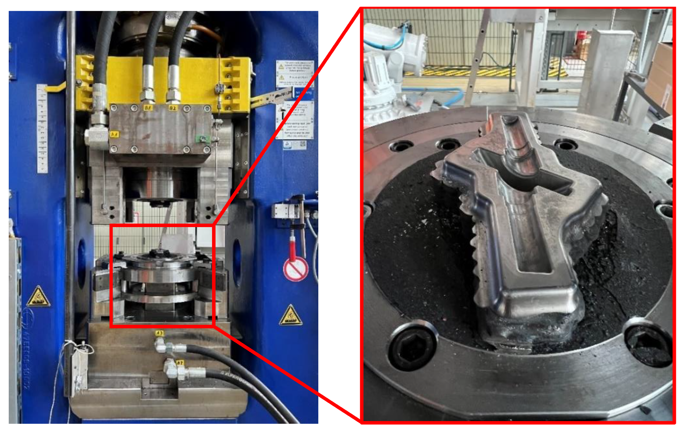
2.2. Forging
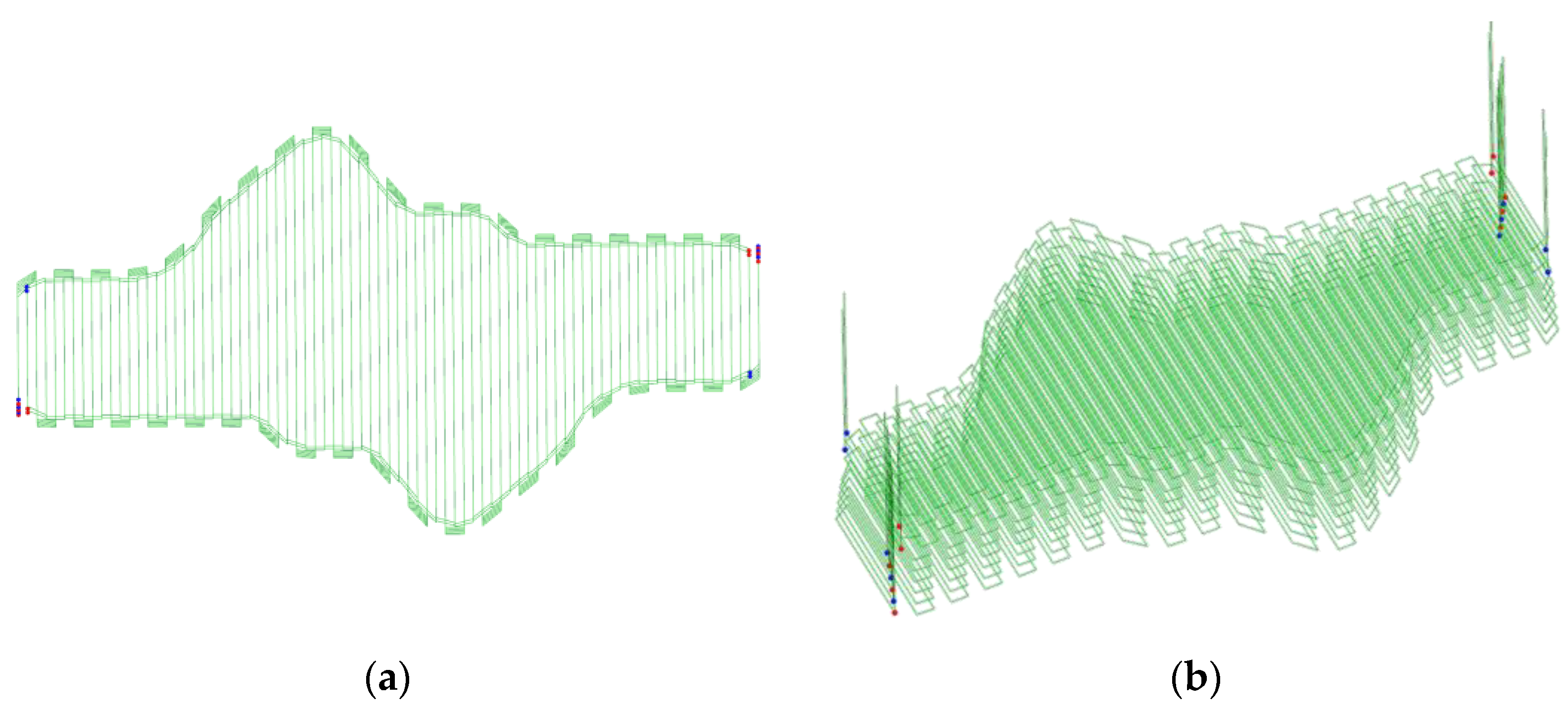
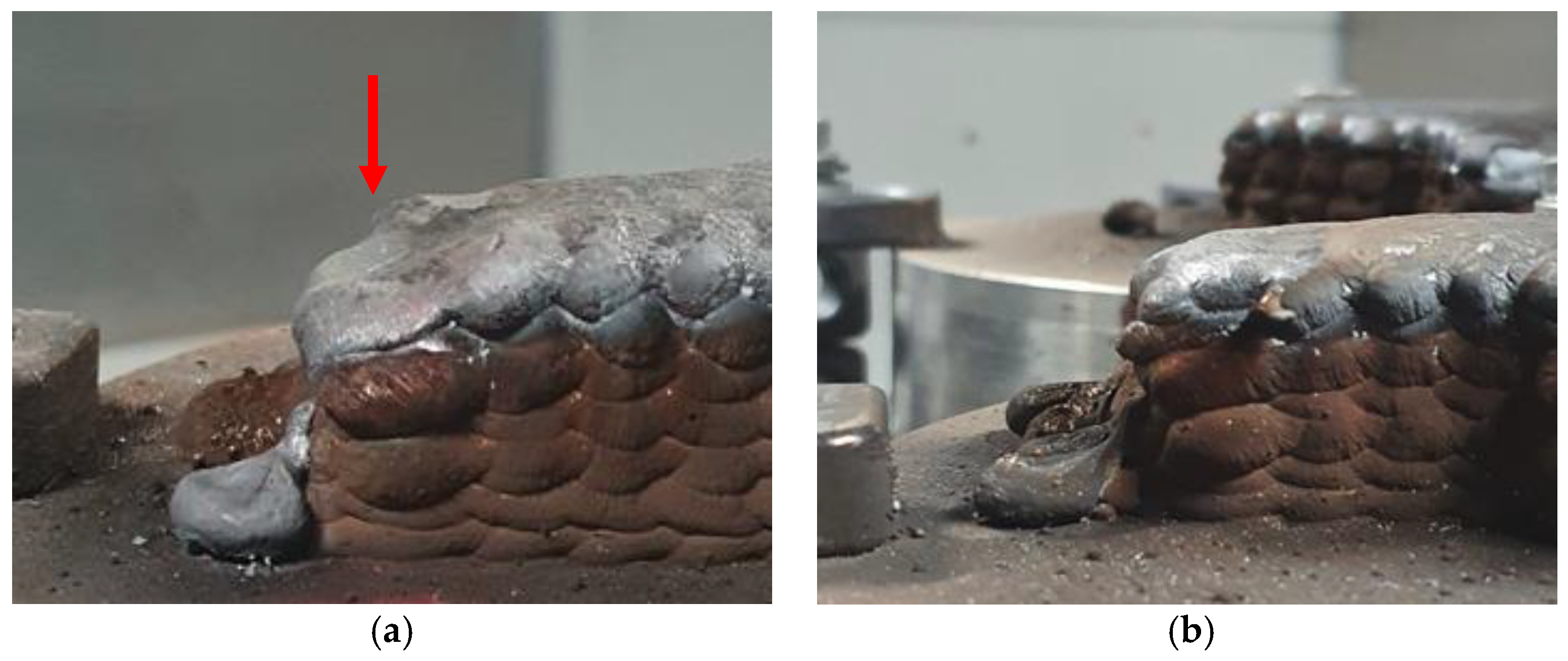
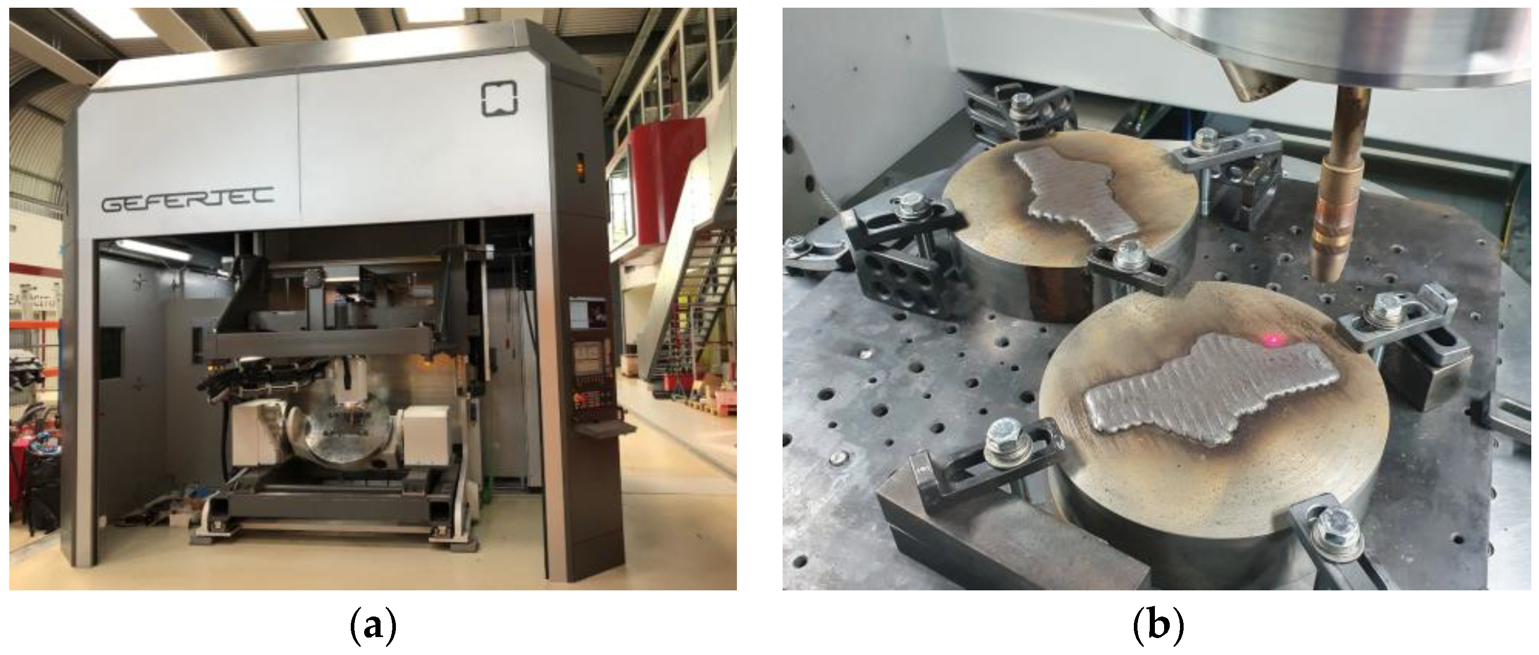
2.3. WA-DED
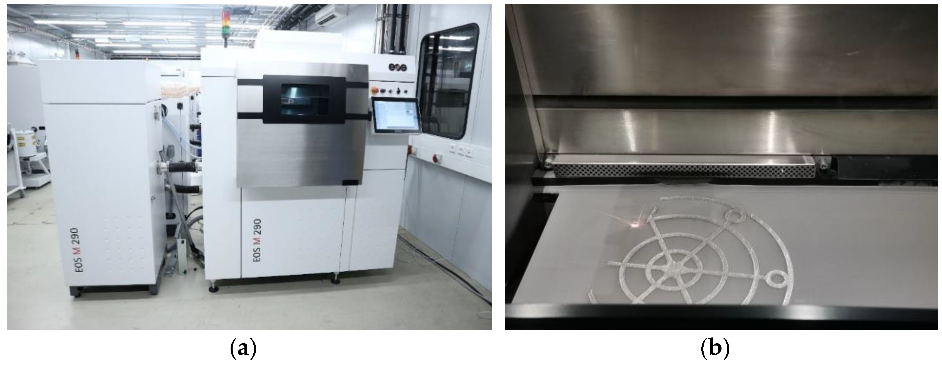
2.4. L-PBF
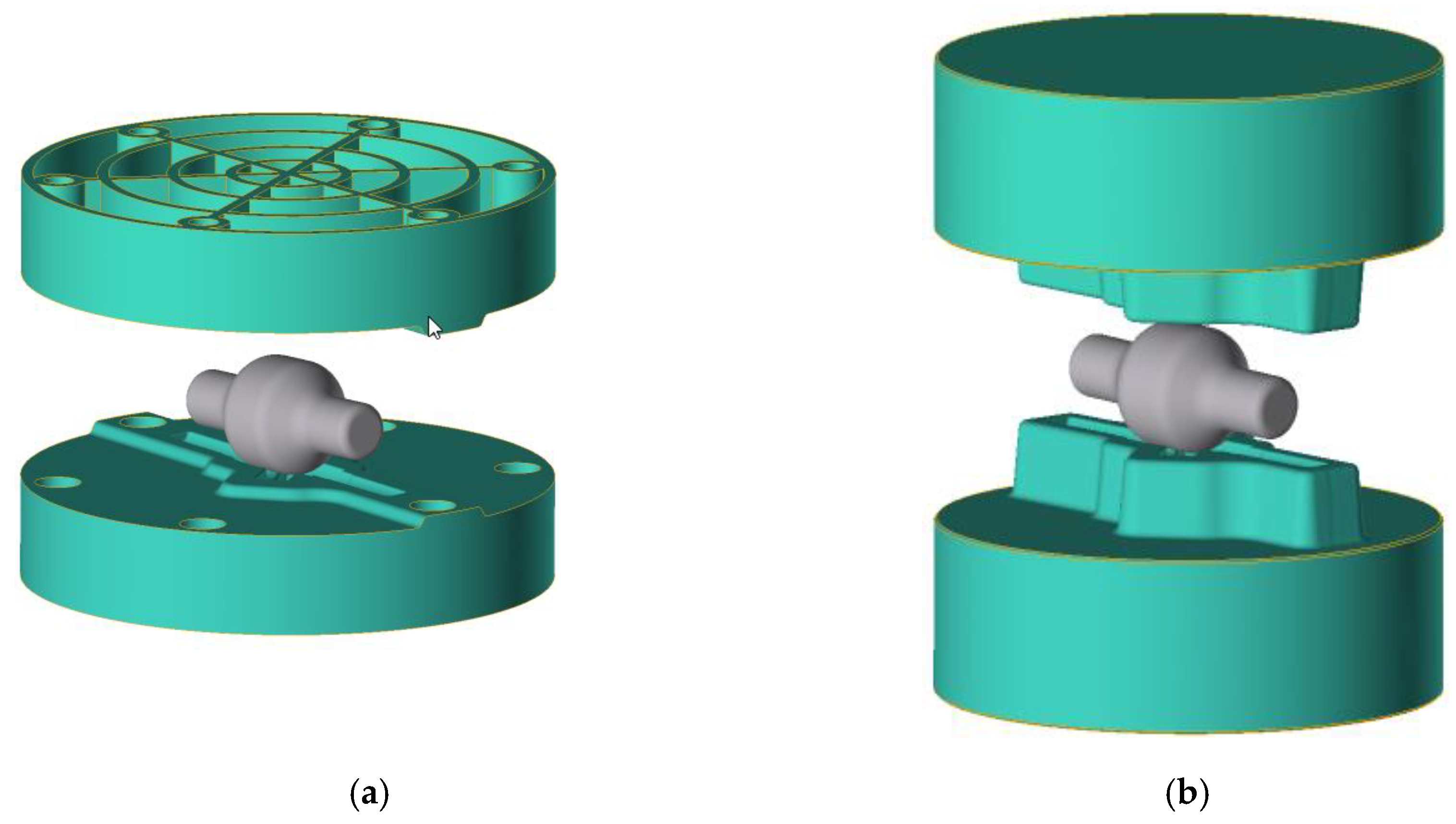
2.5. Forging Simulation
3. Results
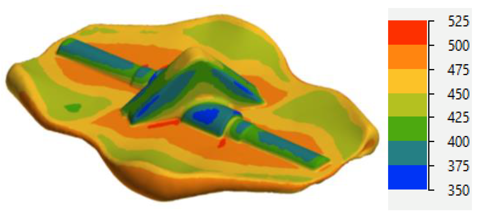
3.1. Simulation of the Forging Process and Die Analysis
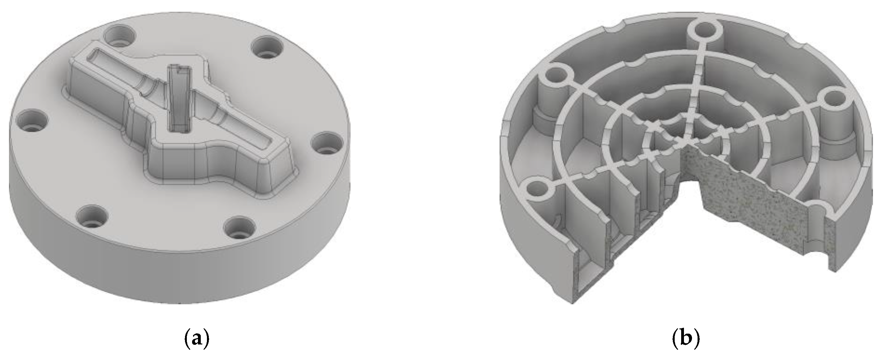
3.2. Design of Hot-Forming Dies for Additive and Hybrid Manufacturing
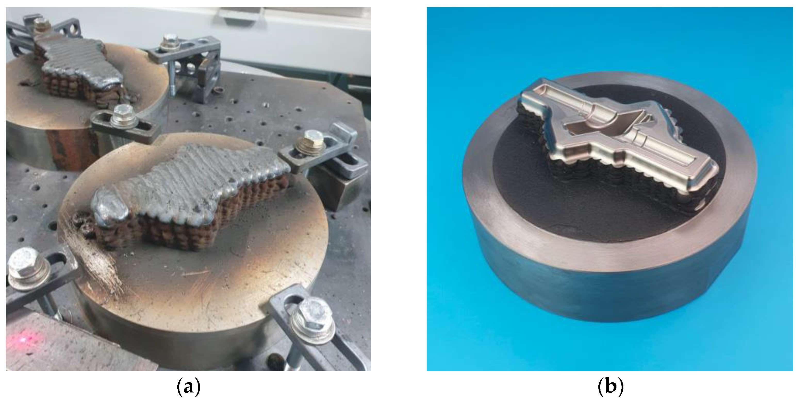
3.3. Manufacturing Process
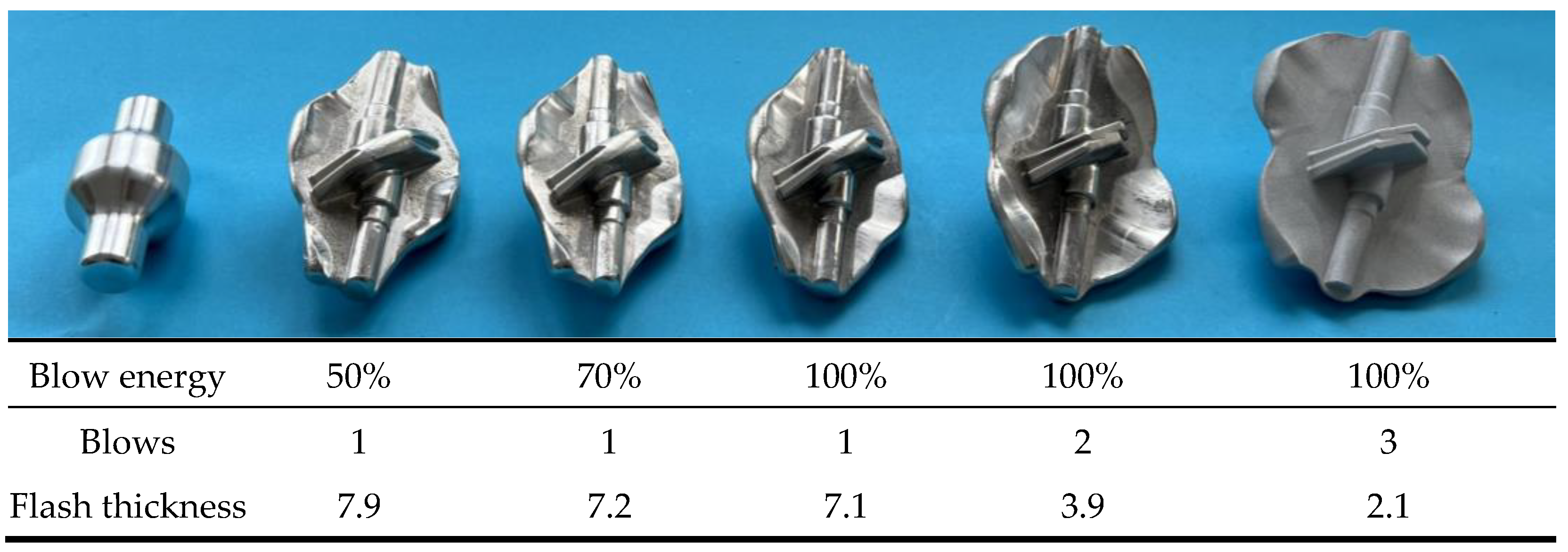
3.4. Forging Trials
4. Discussion
5. Conclusions
- WA-DED is characterized by a higher production rate, but the near-net-shape manufacturing capabilities of this method are limited, and a complex deep die cavity cannot be produced.
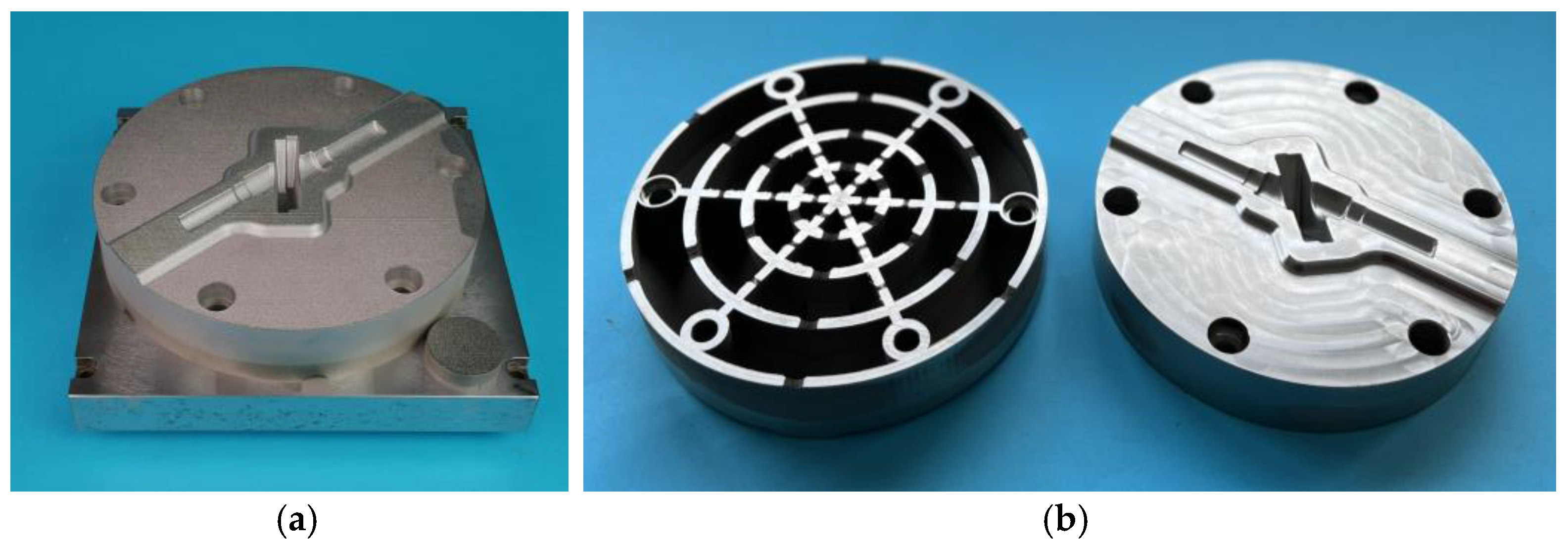
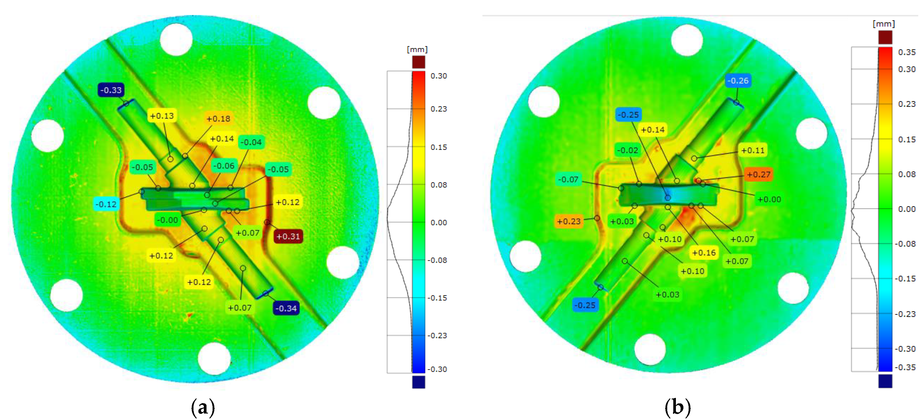
- The L-PBF method makes it possible to produce dies with impressions with a stock to be machined to only 0.3–0.5 mm.
- Through the use of a 2D-lattice structure, the weight of each tool was reduced by 56%, from 14.2 kg to 6.1 kg, in production via L-PBF.
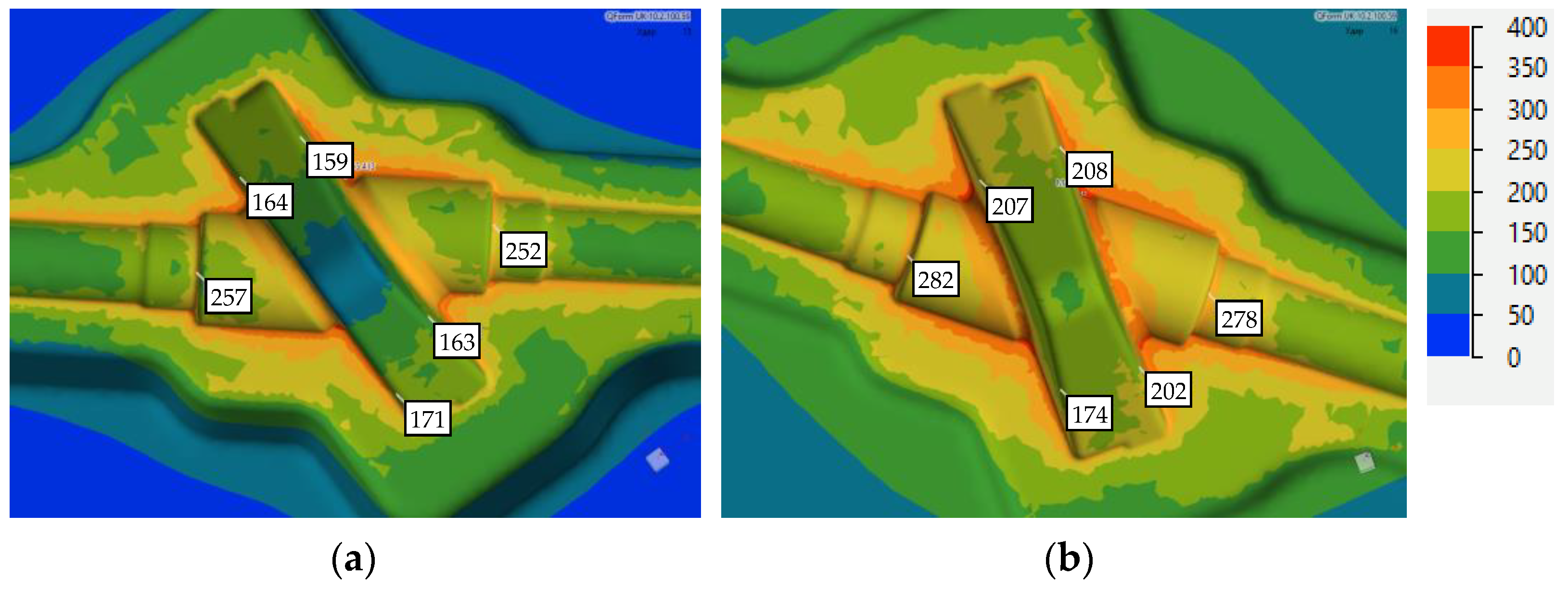
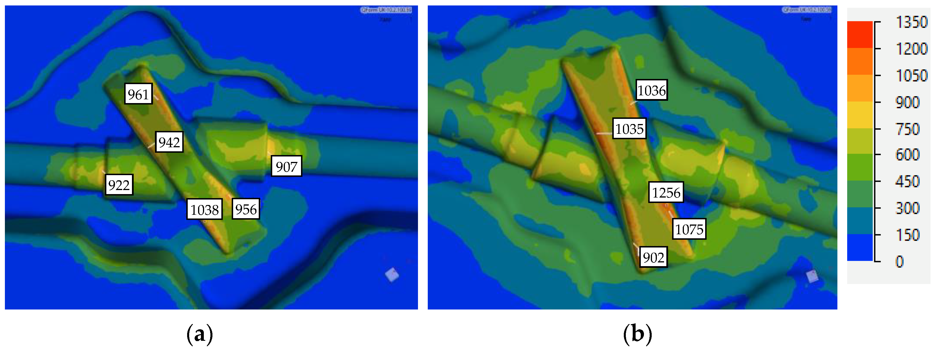
- The forging process was simulated, and the die temperature and stresses were analyzed.
- Additive manufacturing of the forming dies was proven through trial forgings to be effective.
- The fatigue life, fracture toughness, creep resistance and wear behavior of the additive-manufactured forming dies as well as the possibility of their use in industrial applications should be further investigated.
Author Contributions
Funding
Data Availability Statement
Acknowledgments
Conflicts of Interest
References
- Redwood, B.; Schöffer, F.; Garret, B. The 3D Printing Handbook: Technologies, Design and Applications; 3D Hubs: Amsterdam, The Netherlands, 2017. [Google Scholar]
- Popov, V.V.; Fleisher, A. Hybrid Additive Manufacturing of Steels and Alloys. Manuf. Rev. 2020, 7, 6. [Google Scholar] [CrossRef]
- Liu, G.; Zhang, X.; Chen, X.; He, Y.; Cheng, L.; Huo, M.; Yin, J.; Hao, F.; Chen, S.; Wang, P.; et al. Additive Manufacturing of Structural Materials. Mater. Sci. Eng. R Rep. 2021, 145, 100596. [Google Scholar] [CrossRef]
- Rasiya, G.; Shukla, A.; Saran, K. Additive Manufacturing—A Review. Mater. Today Proc. 2021, 47, 6896–6901. [Google Scholar] [CrossRef]
- Gisario, A.; Kazarian, M.; Martina, F.; Mehrpouya, M. Metal Additive Manufacturing in the Commercial Aviation Industry: A Review. J. Manuf. Syst. 2019, 53, 124–149. [Google Scholar] [CrossRef]
- Sun, C.; Wang, Y.; McMurtrey, M.D.; Jerred, N.D.; Liou, F.; Li, J. Additive Manufacturing for Energy: A Review. Appl. Energy 2021, 282, 116041. [Google Scholar] [CrossRef]
- Scholz, S.G.; Howlett, R.J.; Setchi, R. (Eds.) Sustainable Design and Manufacturing: Proceedings of the 8th International Conference on Sustainable Design and Manufacturing (KES-SDM 2021); Smart Innovation, Systems and Technologies; Springer: Singapore, 2022; Volume 262, ISBN 9789811661273. [Google Scholar]
- Sheoran, A.J.; Kumar, H.; Arora, P.K.; Moona, G. Bio-Medical Applications of Additive Manufacturing: A Review. Procedia Manuf. 2020, 51, 663–670. [Google Scholar] [CrossRef]
- DIN EN ISO/ASTM 52900:2022-03; Additive Fertigung—Grundlagen—Terminologie; Deutsche Fassung EN ISO/ASTM 52900:2021. Beuth Verlag GmbH: Berlin, Germany, 2022.
- Sing, S.L.; Yeong, W.Y. Laser Powder Bed Fusion for Metal Additive Manufacturing: Perspectives on Recent Developments. Virtual Phys. Prototyp. 2020, 15, 359–370. [Google Scholar] [CrossRef]
- Kisielewicz, A.; Thalavai Pandian, K.; Sthen, D.; Hagqvist, P.; Valiente Bermejo, M.A.; Sikström, F.; Ancona, A. Hot-Wire Laser-Directed Energy Deposition: Process Characteristics and Benefits of Resistive Pre-Heating of the Feedstock Wire. Metals 2021, 11, 634. [Google Scholar] [CrossRef]
- Ayed, A.; Valencia, A.; Bras, G.; Bernard, H.; Michaud, P.; Balcaen, Y.; Alexis, J. Effects of WAAM Process Parameters on Metallurgical and Mechanical Properties of Ti-6Al-4V Deposits. In Advances in Materials, Mechanics and Manufacturing; Chaari, F., Barkallah, M., Bouguecha, A., Zouari, B., Khabou, M.T., Kchaou, M., Haddar, M., Eds.; Lecture Notes in Mechanical Engineering; Springer International Publishing: Cham, Switzerland, 2020; pp. 26–35. ISBN 978-3-030-24246-6. [Google Scholar]
- Benakis, M.; Costanzo, D.; Patran, A. Current Mode Effects on Weld Bead Geometry and Heat Affected Zone in Pulsed Wire Arc Additive Manufacturing of Ti-6-4 and Inconel 718. J. Manuf. Process. 2020, 60, 61–74. [Google Scholar] [CrossRef]
- Güpner, M.; Rochholz, C.; Bliedtner, J.; Zeidler, H. Process Characterization in Laser Metal Deposition of Hot Work Tool Steel. In Proceedings of the 11th CIRP Conference on Photonic Technologies [LANE 2020], Fürth, Germany, 7–10 September 2020. [Google Scholar]
- Caiazzo, F.; Alfieri, V. Directed Energy Deposition of Stainless Steel Wire with Laser Beam: Evaluation of Geometry and Affection Depth. Procedia CIRP 2021, 99, 348–351. [Google Scholar] [CrossRef]
- Ding, D.; Pan, Z.; Cuiuri, D.; Li, H. Wire-Feed Additive Manufacturing of Metal Components: Technologies, Developments and Future Interests. Int. J. Adv. Manuf. Technol. 2015, 81, 465–481. [Google Scholar] [CrossRef]
- Tyralla, D.; Freiße, H.; Seefeld, T.; Thomy, C.; Dreher, M.; Schnick, M.; Narita, R. Laser Hot Wire Cladding (LHWC) with Single and Multiple Wires for High Deposition Rates and Low Dilution. Weld. Cut. 2020, 19, 220–226. [Google Scholar]
- Gao, M.; Li, L.; Wang, Q.; Ma, Z.; Li, X.; Liu, Z. Integration of Additive Manufacturing in Casting: Advances, Challenges, and Prospects. Int. J. Precis. Eng. Manuf.-Green Tech. 2022, 9, 305–322. [Google Scholar] [CrossRef]
- Chantzis, D.; Liu, X.; Politis, D.J.; El Fakir, O.; Chua, T.Y.; Shi, Z.; Wang, L. Review on Additive Manufacturing of Tooling for Hot Stamping. Int. J. Adv. Manuf. Technol. 2020, 109, 87–107. [Google Scholar] [CrossRef]
- Stache, R. Untersuchungen Zur Herstellung von Werkzeugelementen Für Das Presshärten Mittels Laser Beam Melting. Ph.D. Thesis, Technische Universität Chemnitz, Chemnitz, Germany, 2020. [Google Scholar]
- Müller, B.; Gebauer, M.; Malek, R.; Gerth, N. Metal Additive Manufacturing for tooling applications-Laser Beam Melting technology increases efficiency of dies and molds. In Proceedings of the Metal Additive Manufacturing Conference MAMC, Vienna, Austria, 20–21 November 2014. [Google Scholar]
- Gebauer, M.; Stoll, P.; Müller, B.; Spierings, A.; Polster, S.; Feld, T.; Klinger, M.; Zurbrügg, A. High Performance Sheet Metal Forming Tooling by Additive Manufacturing. In iCAT 2016: Proceedings of the 6th International Conference on Additive Technologies, Nürnberg, Germany, 29–30 November 2016; Interesana-zavod: Ljubljana, Slovenia, 2016. [Google Scholar] [CrossRef]
- Cortina, M.; Arrizubieta, J.; Calleja, A.; Ukar, E.; Alberdi, A. Case Study to Illustrate the Potential of Conformal Cooling Channels for Hot Stamping Dies Manufactured Using Hybrid Process of Laser Metal Deposition (LMD) and Milling. Metals 2018, 8, 102. [Google Scholar] [CrossRef]
- Pujante, J.; González, B.; Garcia-Llamas, E. Pilot Demonstration of Hot Sheet Metal Forming Using 3D Printed Dies. Materials 2021, 14, 5695. [Google Scholar] [CrossRef]
- Huskic, A.; Behrens, B.; Giedenbacher, J.; Huskic, A. Standzeituntersuchungen Generativ Hergestellter Schmiedewerkzeuge. Schmiede J. 2013, 92013, 66–70. [Google Scholar]
- Junker, D.; Hentschel, O.; Schramme, R.; Schmidt, M.; Merklein, M. Performance of Hot Forging Tools Built by Laser Metal Deposition of Hot Work Tool Steel X37CrMoV5-1. In Proceedings of the Laser in Manufacturing Conference, Munich, Germany, 26–29 June 2017. [Google Scholar]
- Frazier, W.E. Metal Additive Manufacturing: A Review. J. Mater. Eng Perform 2014, 23, 1917–1928. [Google Scholar] [CrossRef]
- Haghdadi, N.; Laleh, M.; Moyle, M.; Primig, S. Additive Manufacturing of Steels: A Review of Achievements and Challenges. J. Mater. Sci. 2021, 56, 64–107. [Google Scholar] [CrossRef]
- Foster, J.; Cullen, C.; Fitzpatrick, S.; Payne, G.; Hall, L.; Marashi, J. Remanufacture of Hot Forging Tools and Dies Using Laser Metal Deposition with Powder and a Hard-Facing Alloy Stellite 21®. J. Remanuf. 2019, 9, 189–203. [Google Scholar] [CrossRef]
- Meiners, F.; Ihne, J.; Jürgens, P.; Hemes, S.; Mathes, M.; Sizova, I.; Bambach, M.; Hama-Saleh, R.; Weisheit, A. New Hybrid Manufacturing Routes Combining Forging and Additive Manufacturing to Efficiently Produce High Performance Components from Ti-6Al-4V. Procedia Manuf. 2020, 47, 261–267. [Google Scholar] [CrossRef]
- Bambach, M.; Sizova, I.; Sviridov, A.; Stendal, J.; Günther, M. Batch Processing in Preassembled Die Sets—A New Process Design for Isothermal Forging of Titanium Aluminides. JMMP 2018, 2, 1. [Google Scholar] [CrossRef]
- Kempen, K.; Vrancken, B.; Buls, S.; Thijs, L.; Van Humbeeck, J.; Kruth, J.-P. Selective Laser Melting of Crack-Free High Density M2 High Speed Steel Parts by Baseplate Preheating. J. Manuf. Sci. Eng. 2014, 136, 061026. [Google Scholar] [CrossRef]
- Rack, H.J.; Kalish, D. The Strength, Fracture Toughness, and Low Cycle Fatigue Behavior of 17-4 PH Stainless Steel. Met. Trans. 1974, 5, 1595–1605. [Google Scholar] [CrossRef]
- Concli, F.; Fraccaroli, L.; Nalli, F.; Cortese, L. High and Low-Cycle-Fatigue Properties of 17–4 PH Manufactured via Selective Laser Melting in as-Built, Machined and Hipped Conditions. Prog. Addit. Manuf. 2022, 7, 99–109. [Google Scholar] [CrossRef]
- Carneiro, L.; Jalalahmadi, B.; Ashtekar, A.; Jiang, Y. Cyclic Deformation and Fatigue Behavior of Additively Manufactured 17–4 PH Stainless Steel. Int. J. Fatigue 2019, 123, 22–30. [Google Scholar] [CrossRef]


| Element | Cr | Ni | Cu | Nb | C | Si | Mn | Fe |
|---|---|---|---|---|---|---|---|---|
| Nom. | 15.0–17.0 | 3.0–5.0 | 3.0–5.0 | 0.15–0.45 | <0.07 | <1.00 | <0.70 | Bal. |
| L-PBF | 16.0 | 4.0 | 4.0 | 0.29 | 0.03 | 0.60 | 0.70 | |
| WA-DED | 16.37 | 4.78 | 3.63 | 0.23 | 0.019 | 0.46 | 0.64 |
| Element | Mg | Si | Fe | Cu | Mn | Ti | Zn | Al |
|---|---|---|---|---|---|---|---|---|
| Nom. | 0.35–0.60 | 0.30–0.60 | 0.10–0.30 | <0.10 | <0.10 | <0.10 | <0.15 | Bal. |
| Fact. | 0.436 | 0.596 | 0.186 | 0.004 | 0.012 | 0.015 | 0.003 |
Disclaimer/Publisher’s Note: The statements, opinions and data contained in all publications are solely those of the individual author(s) and contributor(s) and not of MDPI and/or the editor(s). MDPI and/or the editor(s) disclaim responsibility for any injury to people or property resulting from any ideas, methods, instructions or products referred to in the content. |
© 2023 by the authors. Licensee MDPI, Basel, Switzerland. This article is an open access article distributed under the terms and conditions of the Creative Commons Attribution (CC BY) license (https://creativecommons.org/licenses/by/4.0/).
Share and Cite
Alimov, A.; Sviridov, A.; Sydow, B.; Jensch, F.; Härtel, S. Additive Manufacturing of Hot-Forming Dies Using Laser Powder Bed Fusion and Wire Arc Direct Energy Deposition Technologies. Metals 2023, 13, 1842. https://doi.org/10.3390/met13111842
Alimov A, Sviridov A, Sydow B, Jensch F, Härtel S. Additive Manufacturing of Hot-Forming Dies Using Laser Powder Bed Fusion and Wire Arc Direct Energy Deposition Technologies. Metals. 2023; 13(11):1842. https://doi.org/10.3390/met13111842
Chicago/Turabian StyleAlimov, Artem, Alexander Sviridov, Benjamin Sydow, Felix Jensch, and Sebastian Härtel. 2023. "Additive Manufacturing of Hot-Forming Dies Using Laser Powder Bed Fusion and Wire Arc Direct Energy Deposition Technologies" Metals 13, no. 11: 1842. https://doi.org/10.3390/met13111842
APA StyleAlimov, A., Sviridov, A., Sydow, B., Jensch, F., & Härtel, S. (2023). Additive Manufacturing of Hot-Forming Dies Using Laser Powder Bed Fusion and Wire Arc Direct Energy Deposition Technologies. Metals, 13(11), 1842. https://doi.org/10.3390/met13111842