Abstract
In the automotive production line, a single pair of electrodes is employed to produce hundreds of consecutive welds before undergoing dressing or replacement. In consecutive resistance spot welding (RSW) involving Zn-coated steels, the electrodes undergo metallurgical degradation, characterized by Cu-Zn alloying, which impacts the susceptibility to liquid metal embrittlement (LME) cracking. In the present investigation, the possibility of LME crack formation in uncoated TRIP steel joints during consecutive RSW (involving 400 welds in galvannealed and uncoated TRIP steels) was investigated. The results have shown that different Cu-Zn phases were formed on the electrode surface because of its contamination with Zn from the galvannealed coating. Therefore, during the welding of the uncoated TRIP steel, the heat generated at the electrode/sheet interface would result in the melting of the Cu-Zn phases, thereby exposing the uncoated steel surface to molten Zn and Cu, leading to LME cracking. The cracks exhibited a maximum length of approximately 30 µm at Location A (weld center) and 50 µm at Location B (shoulder of the weld). The occurrence and characteristics of the cracks differed depending on the location as the number of welds increased due to the variation in Zn content. Type A cracks did not form when the number of welds was less than 280. Several cracks with a total length of approximately 30 μm were suddenly formed between 280 and 400 welds. On the other hand, type B cracks began to appear after 40 welds. However, the number and size of these exhibited inconsistency as the number of welds increased. Overall, the results have shown that small LME cracks can form even in uncoated steels during consecutive welding of Zn-coated and uncoated steel joints.
1. Introduction
In recent years, addressing the reduction of CO2 emissions through manufacturing lightweight and eco-friendly vehicles has become a concerning issue in the automobile industry [1,2]. Furthermore, enhancing the rigidity of the vehicle bodies to ensure passenger safety remains a key priority. To meet these requirements, the utilization of advanced high-strength steels (AHSSs) is increasing. These steels offer high strength and are engineered with improved formability, enabling the fabrication of vehicle structures using thinner sheets [3,4,5]. Transformation-induced plasticity (TRIP) steels, in particular, provide an outstanding combination of strength and ductility, making them an attractive material for producing lighter and more crash-resistant vehicles [6,7]. This remarkable combination of strength and ductility is primarily attributed to the presence of retained austenite. During deformation, this retained austenite undergoes an austenite-to-martensite transformation, resulting in substantial work hardening and an increase in both uniform elongation and strength [8,9].
To protect the car body against corrosion, zinc-based coatings are usually applied on the surface of the automotive steel sheets [10,11]. However, during the RSW, which is widely employed in the automotive assembly, the presence of zinc coatings can introduce the risk of Zn-assisted liquid metal embrittlement (LME) cracking, which can cause brittle failure in an ordinarily ductile material. Consequently, numerous studies have been devoted to understanding and mitigating LME cracks in the RSW of Zn-coated AHSSs [8,12,13,14,15]. The occurrence of LME cracking depends on material-related factors, such as the composition and microstructure of the material and the properties of the Zn-based coating layer [16]. However, it has been shown that the formation and severity of LME cracks are strongly influenced by process parameters and factors that affect the thermal–mechanical conditions that the material is subjected to during the welding process, such as the heat input, electrode geometry, and misalignments between the electrode and the workpiece [14,16,17]. For example, Jin et al. [14] investigated the effect of process parameters on LME crack sensitivity during the RSW of Zn-coated AHSS. They observed that in joints with equivalent nugget diameters, a higher sensitivity to LME occurred in cases where high welding current and short welding times were used compared to those with low welding current and longer welding times. This is because the high current and short time combination led to faster weld nugget growth, which in turn rapidly elevated the surface temperature. This temperature increase, coupled with the subsequent cooling from the electrode, contributed to the heightened LME sensitivity. DiGiovanni et al. [17] demonstrated that the geometry of the electrode plays a pivotal role in determining both the severity of LME and the distribution of crack locations. Specifically, they found that a radius-tip electrode resulted in minimal cracking, whereas an electrode with a truncated cone shape exhibited severe LME, particularly in the shoulder region. DiGiovanni et al. [18] also showed that electrode misalignment also plays a role in the LME severity. It has been observed that as the angle of electrode misalignment increases, the severity of LME also increases. Additionally, it was concluded that electrode misalignment leads to the deformation of the workpiece, which in turn results in external mechanical stress. Murugan et al. [19] demonstrated that the radius-type electrode exhibited lower sensitivity to LME than the dome-type electrode in RSW of Zn coated steels. They also showed that the radius of curvature is the most crucial design parameter of the electrode that governs LME cracking. As the radius of curvature increased, the current density decreased, and the contact area at the electrode/sheet interface increased. These resulted in lower temperatures and reduced thermal stress, ultimately leading to a decreased tendency for LME formation.
In the actual automobile production line, various combinations of materials are continuously welded by an automated robot equipped with a pair of electrodes. The electrodes are employed to create hundreds of welds before they are either dressed or replaced. [6]. As a result, the electrodes undergo various types of modifications (including both geometrical and metallurgical changes), which can significantly affect the thermal-mechanical conditions at the electrode-sheet interface [6,20]. Kaisar et al. [6] investigated the effect of electrode degradation on LME cracking in consecutive RSW of galvannealed TRIP steel by producing 400 consecutive welds. The electrode underwent geometrical degradation, specifically an increase in the radius of curvature and face diameter. As the number of welds increased, the radius of curvature also increased, which led to an expanded electrode-sheet contact area. Consequently, the current density at the electrode-sheet interface decreased, and there was an increase in heat dissipation through the electrode. This combination resulted in a decrease in temperature and thermal stress at the electrode-sheet interface. The severity of LME cracking decreased with consecutive welding. Furthermore, it was observed that the electrode underwent metallurgical degradation, leading to the formation of a Cu-Zn-Fe layer on the electrode surface. This was found to have some impact on the occurrence of LME cracking.
The RSW of coated and uncoated steels using different pairs of electrodes in the actual automobile production line would be challenging and time consuming, thereby increasing the production cost. Therefore, the same pair of electrodes can be used to make hundreds of welds in coated and uncoated steels being dressed or changed. Since it has been shown that the electrodes would be contaminated with Zn during the consecutive welding of the Zn-coated steels [6], there is a possibility that the Zn in the contaminated electrodes can lead to the formation of liquid Zn and thus LME cracking in the uncoated steel joints in the consecutive welding. However, to the authors knowledge, this has never been investigated. Therefore, to address this concern, the possibility of the formation of LME cracks even in uncoated steel joints during consecutive RSW involving coated and uncoated TRIP steels was investigated in the present study. Consecutive RSW involving 400 welds of both coated and uncoated TRIP steels was conducted. The occurrence or absence of LME cracks in the uncoated steel joints was investigated.
2. Materials and Methods
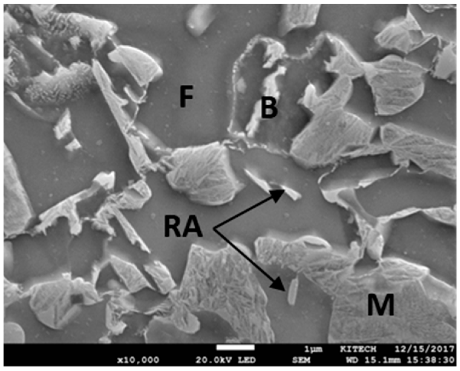
The base material (BM) used was an uncoated TRIP steel with a thickness of 1.2 mm. The chemical composition and mechanical properties are shown in Table 1. The microstructure of the BM consisted of ferrite (F), martensite (M), bainite (B), and retained austenite (RA), as shown in Figure 1.

Table 1.
Chemical composition and mechanical properties of the base metal [6].

Figure 1.
Microstructure of the base metal.
The welding process was conducted using an MFDC inverter servo C-type RSW machine. The electrode used was a dome-type Cu-Cr electrode with a tip diameter of 6 mm (ISO F1-16-20-40-6) electrode. The welding conditions used are shown in Table 2. To stabilize the electrode and enhance reproducibility, 20 welds were initially produced using the as-received electrode at a welding current that was 1.0 kA lower than the experimental welding current, as previously described in [6,21]. This step was taken before implementing the experimental welding schedule, which is illustrated in Figure 2. The galvannealed TRIP steel (coating thickness of ~6 μm) was employed to induce electrode degradation [6]. It has the same thickness, composition, and mechanical properties as the uncoated BM. In all cases, a thicker low carbon steel sheet (1.6 mm) was used as the bottom sheet to enable the use of the high welding current without expulsion [6].
Table 2.
Welding conditions used for the consecutive welding (* 1 cycle = 16.67 ms).
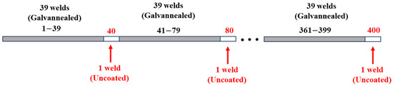
Figure 2.
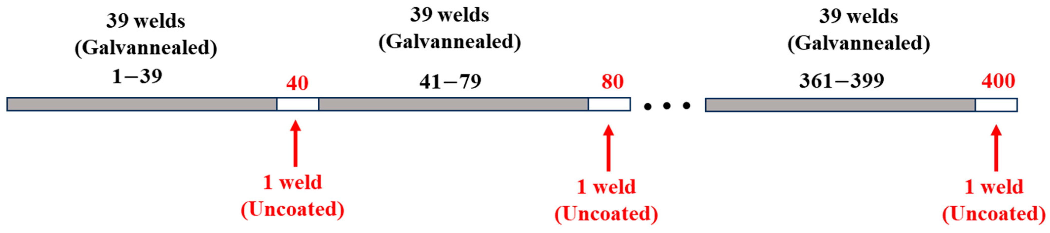
Sequence used in the consecutive welding of the galvannealed and uncoated TRIP steels.
As illustrated in Figure 2, the experimental schedule involved performing 39 consecutive welds on the galvannealed TRIP steel, followed by the subsequent 1 weld on the uncoated TRIP steel. This sequence was repeated until a total of 400 consecutive welds were produced. The welding parameters used are shown in Table 2. After welding, the uncoated TRIP steel welds (40th, 80th, … and 400th welds) were analyzed to determine the presence or absence of LME cracks. The samples were cut through the center of the welds, then mounted, ground, and polished using standard procedure for metallographic sample preparation. The analysis of the LME cracks was conducted using scanning electron microscopy (SEM) as well as electron backscattered diffraction (EBSD) in a 200 FEG (C-Nano) system at the Converging Materials Core Facility, Dong-Eui University, Republic of Korea.
3. Results and Discussion
3.1. LME Cracks in the Uncoated TRIP Steel Joints
The typical macrostructures of the uncoated TRIP steel joints are shown in Figure 3. As mentioned in Section 2, a thicker low carbon steel sheet (1.6 mm) was used as the bottom sheet to enable the use the use of high welding current without expulsion. Therefore, the top sheet in Figure 3 is the uncoated TRIP steel, while the bottom sheet is the low carbon steel. Referring to Figure 3a, the first weld made on the uncoated TRIP steel (40th weld in the consecutive welding) exhibited a nugget diameter of about 6.9 mm. The nugget size decreased slightly with increasing number of welds, which can be attributed to the reduced current density caused by the geometrical degradation of the electrodes [6].
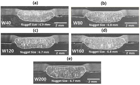
Figure 3.
Typical macrostructures of the uncoated TRIP steel joints; (a) 40th weld, (b) 80th weld, (c) 120th weld, (d) 160th weld, (e) 200th weld.
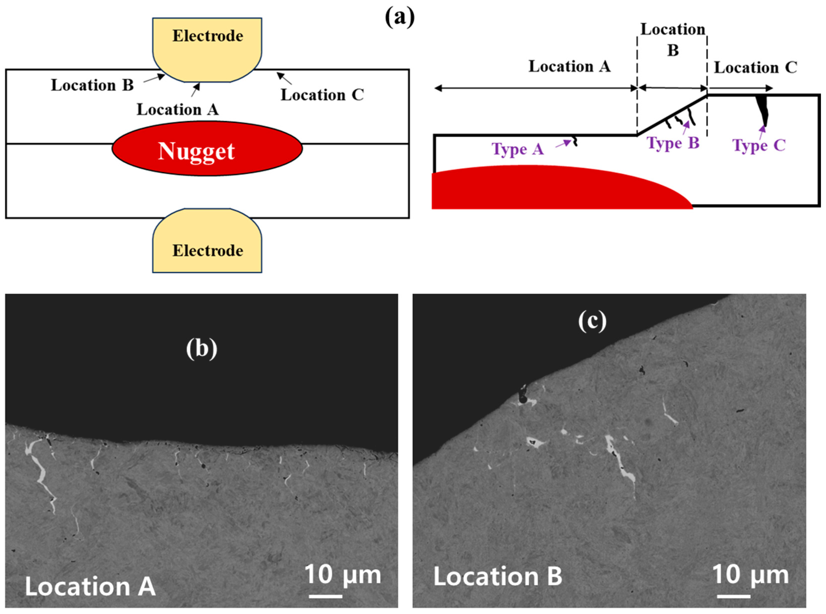
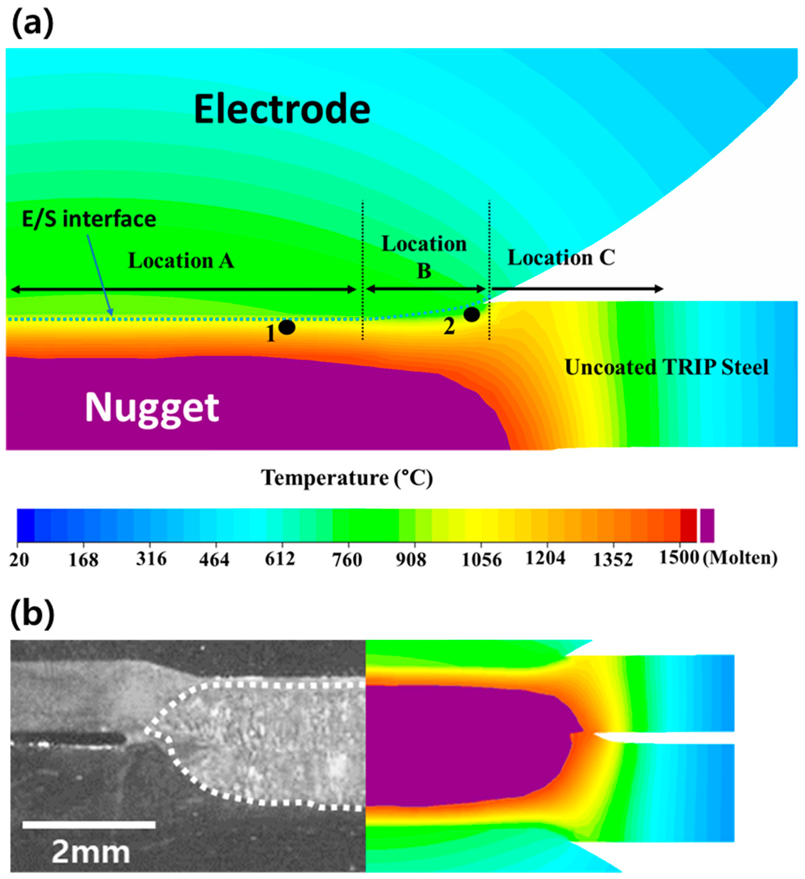
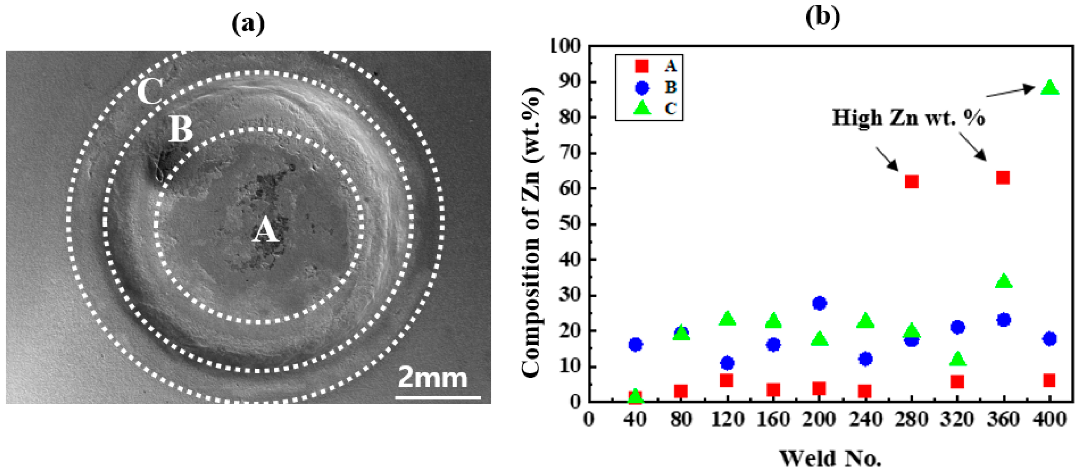
As illustrated in Figure 4, the locations where LME cracks commonly form in RSW are typically divided into three: Location A, Location B, and Location C [6]. Location A, which is at the center of the weld, corresponds to the region that is in direct contact with the electrode. In Location B (situated at the shoulder of the weld), direct contact is not established between the electrode surface and the sheet surface at the initial stage. However, as the welding progresses, the electrode surface eventually touches the sheet, forming a shoulder-like inclined surface [22]. Location C (periphery of the weld) exists at the edge of the electrode/sheet interface. This location does not come into contact with the electrode throughout the welding process. The LME cracks in these specific locations have been categorized as type A, type B, and type C cracks.
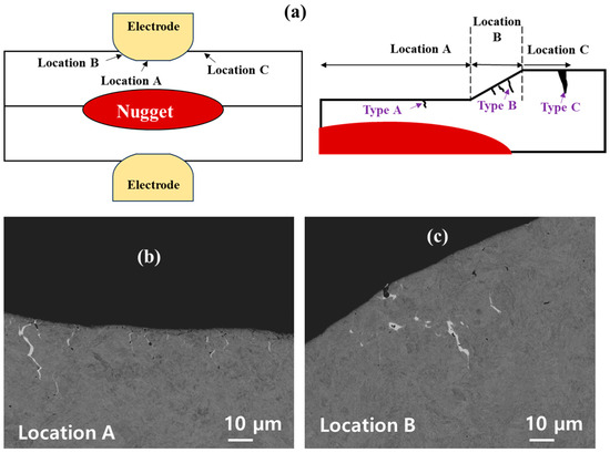
Figure 4.
(a) Classification of LME cracks in RSW and typical cracks observed in the present investigation (b) Location A (W160), (c) Location B (W280).
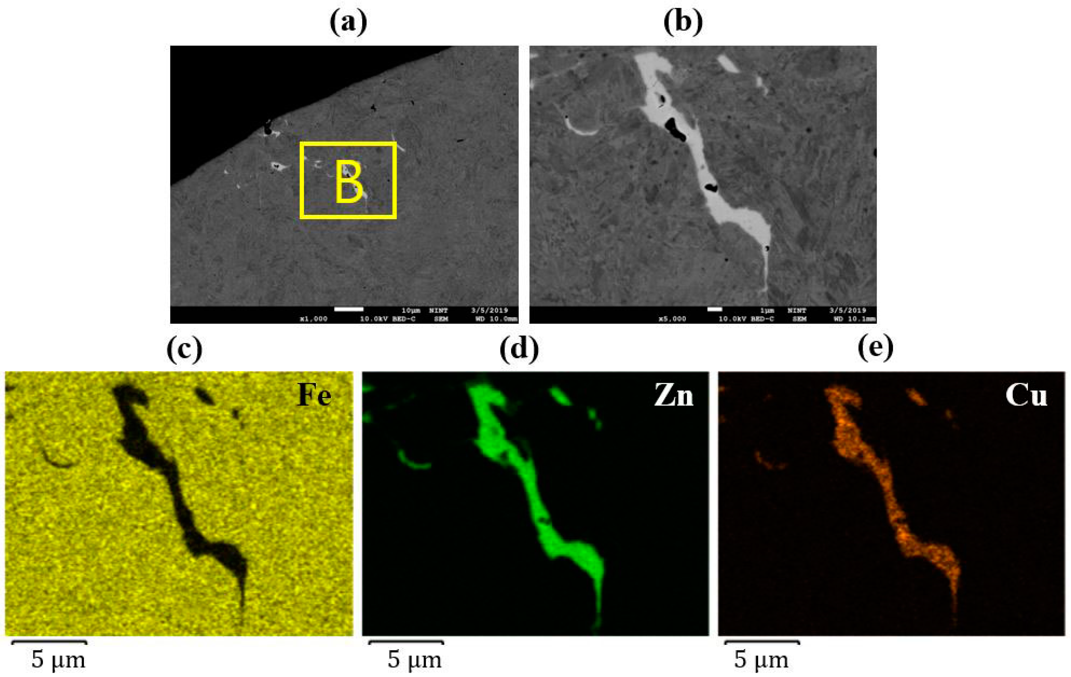
In the current investigation, very small cracks were observed in Locations A and B on the surface of the uncoated TRIP steel joints, depending on the weld number during the consecutive welding, as discussed in Section 3.3. However, no cracks were observed in Location C in all the joints, regardless of the weld number. Figure 4b show typical SEM images of the cross-section of the joints, with the cracks in locations A and B, respectively. An EDS elemental analysis was conducted to confirm whether these are LME cracks. As shown in Figure 5 and Figure 6, the EDS elemental mapping results indicate the presence of Zn in the cracks. As shown in Figure 5 and Figure 6, besides the presence of the Zn element, Cu, also known as embrittler [23], was detected in both the type A and type B cracks. However, Zn was observed both on the surface of the sheet and within the cracks, whereas Cu was primarily observed inside the crack. The presence of both Zn and Cu inside cracks indicates that they are LME cracks. The possible formation mechanism is discussed in Section 3.2.
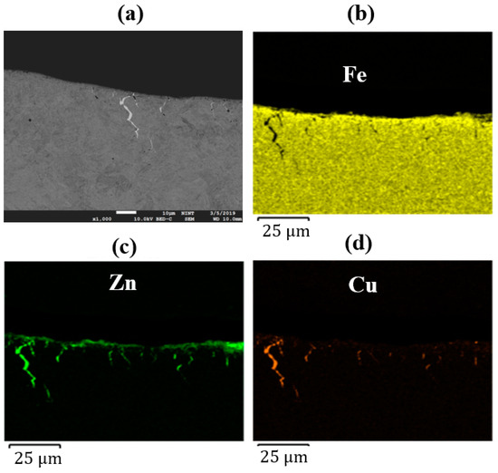
Figure 5.
EDS elemental mapping in Location A (W160): (a) SEM image of the location, (b) Fe, (c) Zn, and (d) Cu distribution.

Figure 6.
EDS elemental mapping in Location B (W280): (a) SEM image of the location; (b) higher magnification of region B in (a); (c) Fe, (d) Zn, and (e) Cu distribution.
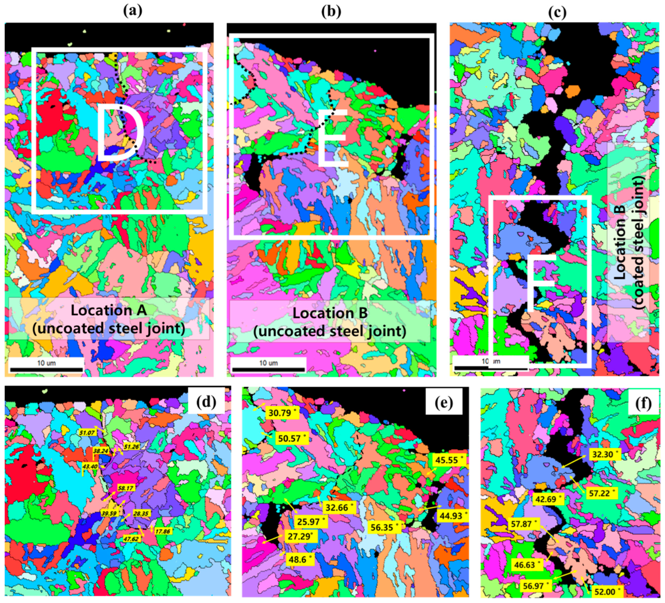
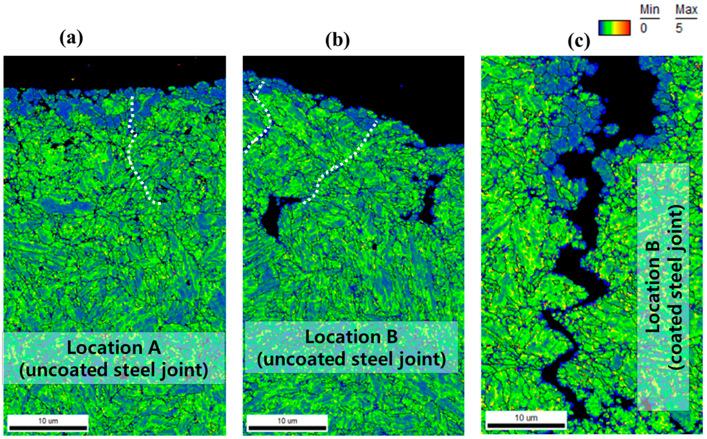
EBSD analysis was conducted to characterize these cracks further, as shown in Figure 7. The typical LME crack in the coated steel joint was also analyzed for comparison. Referring to Figure 7, it can be observed that the cracks in the uncoated steel joints (indicated by the black dotted line in Figure 6a,b) have a length of about 10–15 µm, which is much lower than that of the cracks in the coated steel joints (about 46 µm, Figure 7c). Nevertheless, they exhibit similar characteristics. It is well known that liquid metal penetration occurs along high angle grain boundaries (HAGBs) (misorientation angles above 15°) due to their higher grain boundary energy [24]. Therefore, the misorientation angle across the cracks was obtained, as shown in Figure 7c,d. All the misorientation angles are above 15º, which indicates HAGBs. Furthermore, among the HAGBs, LME cracks predominantly propagate along the prior austenite grain boundaries (PAGBs) [12], which typically exhibit a misorientation angle in the range of 20–50° [25]. Referring to Figure 7c,d, it is evident that the misorientation angles for the cracks observed in the uncoated steel joints mostly fall within this range. However, some of them exceeded the range. The kernel average misorientation (KAM) map was also obtained to understand the local misorientation and plastic strain further. As shown in Figure 8, there is a relatively uniform distribution of KAM values across all the locations, without any regions displaying high KAM values. This suggests that the grains near the cracks did not undergo any plastic deformation, indicating a complete brittle fracture.
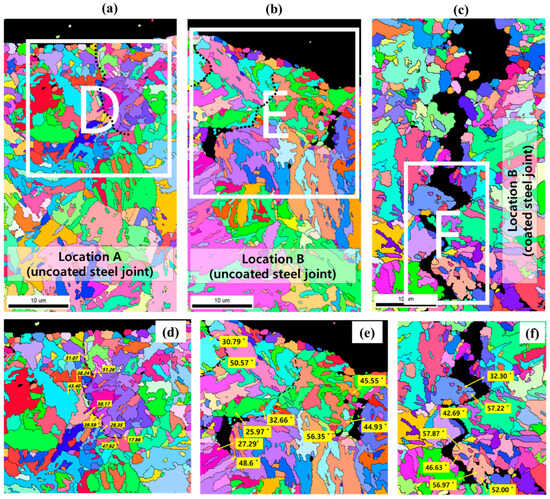
Figure 7.
Typical IPF for (a,b) uncoated steel and (c) coated steel joints; (d–f) misorientation across the cracks in regions D–F, respectively.
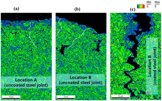
Figure 8.
EBSD KAM for the corresponding locations in Figure 7 (a–c).
3.2. Formation Mechanism of the LME Cracks in the Uncoated TRIP Steel Joint
In the preceding section, the cracks formed in the uncoated steel joints during the consecutive welding (involving both coated and uncoated steels) were identified as LME cracks. In this section, the mechanism for the formation of these cracks is discussed.
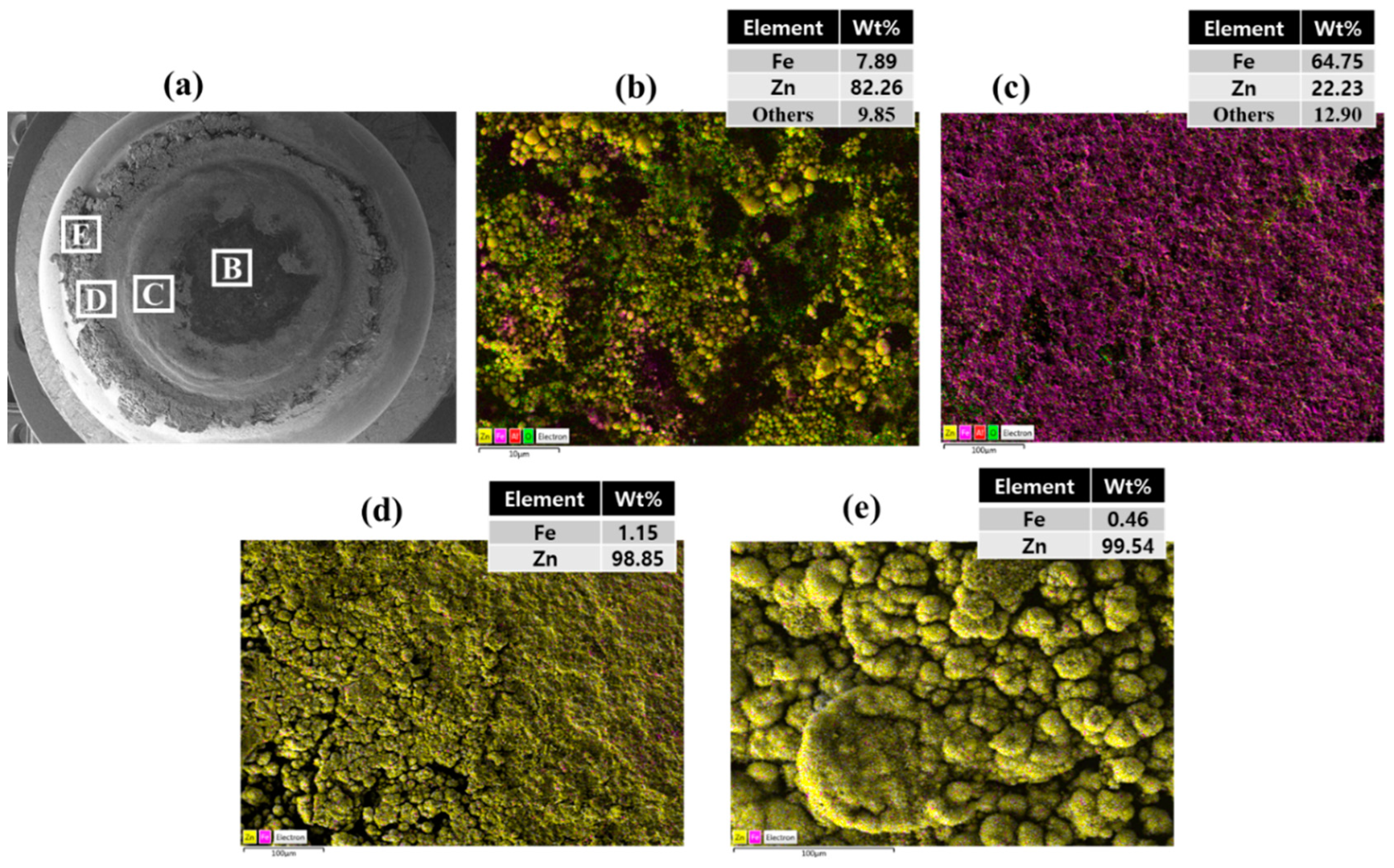
As illustrated in Figure 1, in the present investigation, the welding sequence involved making 39 welds in the galvannealed steel followed by 1 weld in the uncoated steel until 400 welds were made. During the consecutive welding of galvannealed TRIP steel, owing to the heat generated at the electrode/sheet (E/S) interface, the Zn-Fe alloy coating would melt and react with the Cu electrode, thereby contaminating the electrode surface. To investigate this phenomenon, EDS analysis was conducted on the surface and cross-section of the electrode. The analysis was conducted after making the 400th weld, as it would be challenging to analyze the electrode surface after each weld. The results, shown in Figure 9 and Figure 10, clearly indicate the presence of mostly Zn and some Fe on the electrode surface, confirming the contamination of the electrode surface. Kaisar et al. [6] conducted a detailed analysis of the phases formed on the electrode surface during the consecutive welding of the galvannealed TRIP steel and showed that the Zn from the electrode would react with Cu to form various types of Cu-Zn phases (α-CuZn, β-CuZn, and γ-CuZn phases) depending on the location, temperature, and exposure time between the molten Zn and the Cu electrode. Therefore, during the welding of the uncoated steel in consecutive welding, these Cu-Zn phases may melt, also depending on the temperature at the electrode/sheet (E/S) interface.
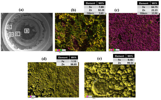
Figure 9.
EDS elemental analysis of the surface of the electrode after making the 400th weld: (a) SEM image of the electrode surface showing the analyzed regions; (b–e) Elemental mapping results and the average composition in the corresponding regions shown in (a).
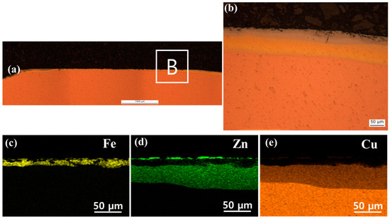
Figure 10.
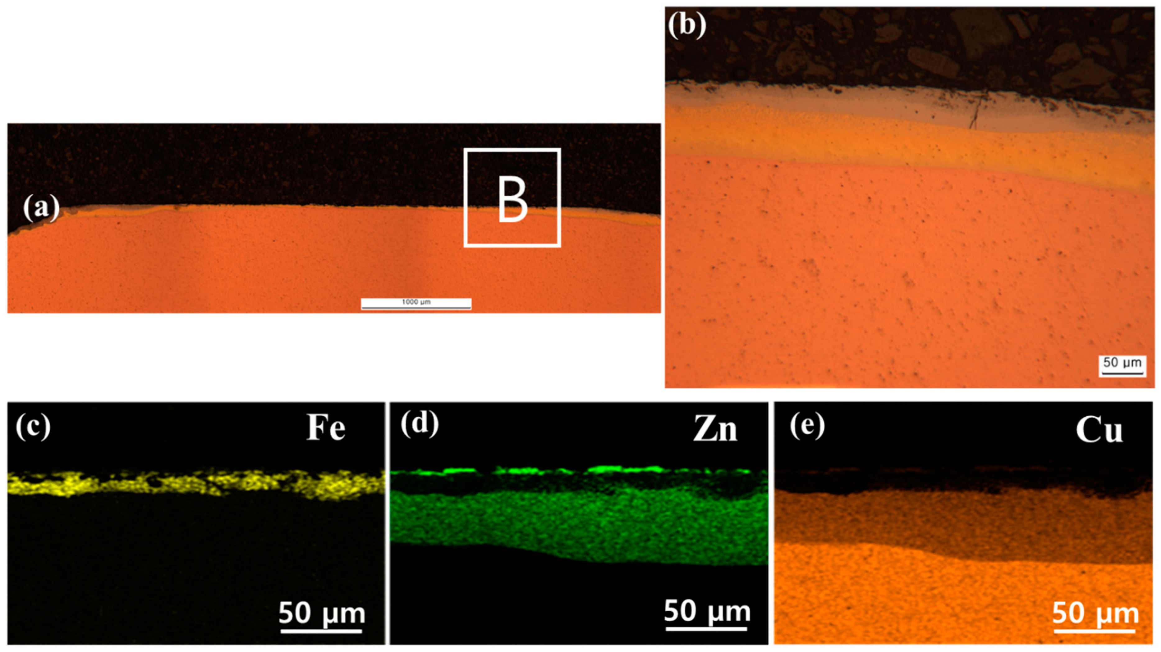
EDS elemental analysis on the cross-section of the electrode after making the 400th weld: (a) cross-section of the electrode; (b) magnified image of the region (b) in (a); (c–e) Elemental mapping results of the region identified with the yellow dotted box in (b).
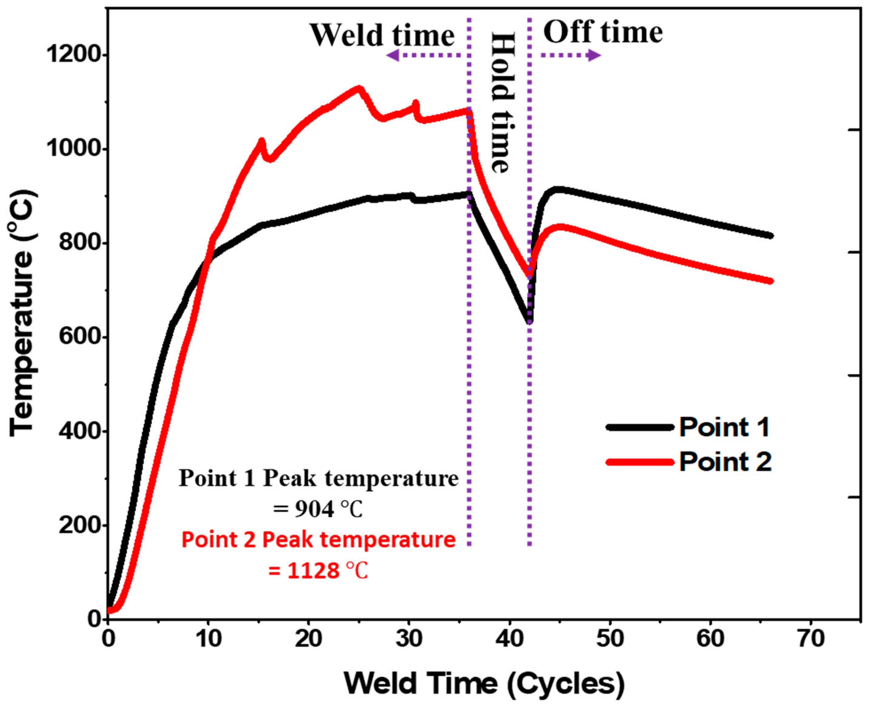
Therefore, SORPAS ® software (V 14.8) was used to obtain the temperature distribution in the uncoated steel joint. However, it should be noted the current density and, consequently, temperature distribution may vary as the number of welds increases due to the geometrical degradation of the electrode [6]. Nevertheless, the results (Figure 11 and Figure 12) provide a general idea of the temperature range in different joint areas. It can be seen that the peak temperature near the E/S interface falls within the range of approximately 900–1200 °C. Referring to Figure 12, as the welding current was applied, the temperature increased rapidly at the initial stage. Then, it increased at a significantly lower rate until the end of the welding time. The temperature experienced a sudden drop during the hold time when the welding current was switched off. However, it increased again due to the withdrawal of the water-cooled electrodes from the sheet surfaces. The peak temperature reached at points 1 and 2 was 904 and 1128 °C, respectively. Therefore, some of the Cu-Zn phases on the electrode surface would melt (melting points of α-CuZn, β-CuZn, and γ-Cu-Zn are 1085, 903, and 835 °C, respectively [26]), thereby exposing the uncoated steel surface to liquid Zn and Cu. This would lead to LME cracking under the generated stress.

Figure 11.
SORPAS simulation results: (a) Typical temperature distribution, (b) comparison of the cross-section obtained using experiment and simulation.
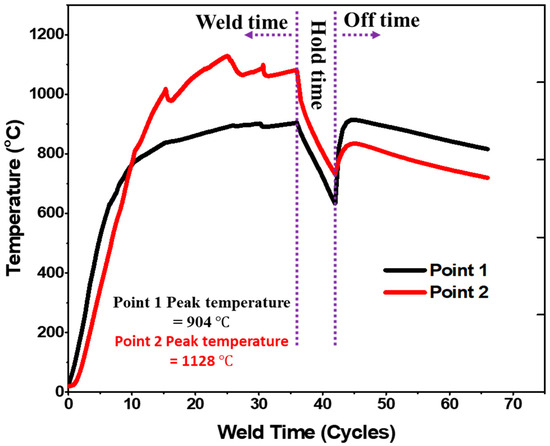
Figure 12.
Temperature profiles at points 1 and 2 in Figure 11 obtained using SORPAS software (* 1 cycle = 16.67 ms).
As shown in Figure 11, heat is generated in the system during the welding process, with melting occurring at the faying interface due to the highest heat generation. However, the sheet surface near the E/S interface experiences a significantly lower temperature rise. Consequently, it experiences a nonlinear thermal gradient, leading to the development of tensile stress in this region. The availability of liquid Zn and Cu would then trigger the LME cracking under the generated stress. Despite the extensive research conducted on LME over the years, a universally accepted mechanism remains elusive [23]. Nevertheless, it has been attributed mainly to stress-assisted Zn diffusion along the grain boundary at the crack tip, which reduces the surface energy of the grain boundary, leading to the decohesion of atoms at the grain boundary. This process may lead to the crack reopening, allowing fresh liquid embrittler to infiltrate, thus reinitiating the mechanism and extending the crack further [23,27].
3.3. Statistics of the LME Cracks in the Consecutive Welding
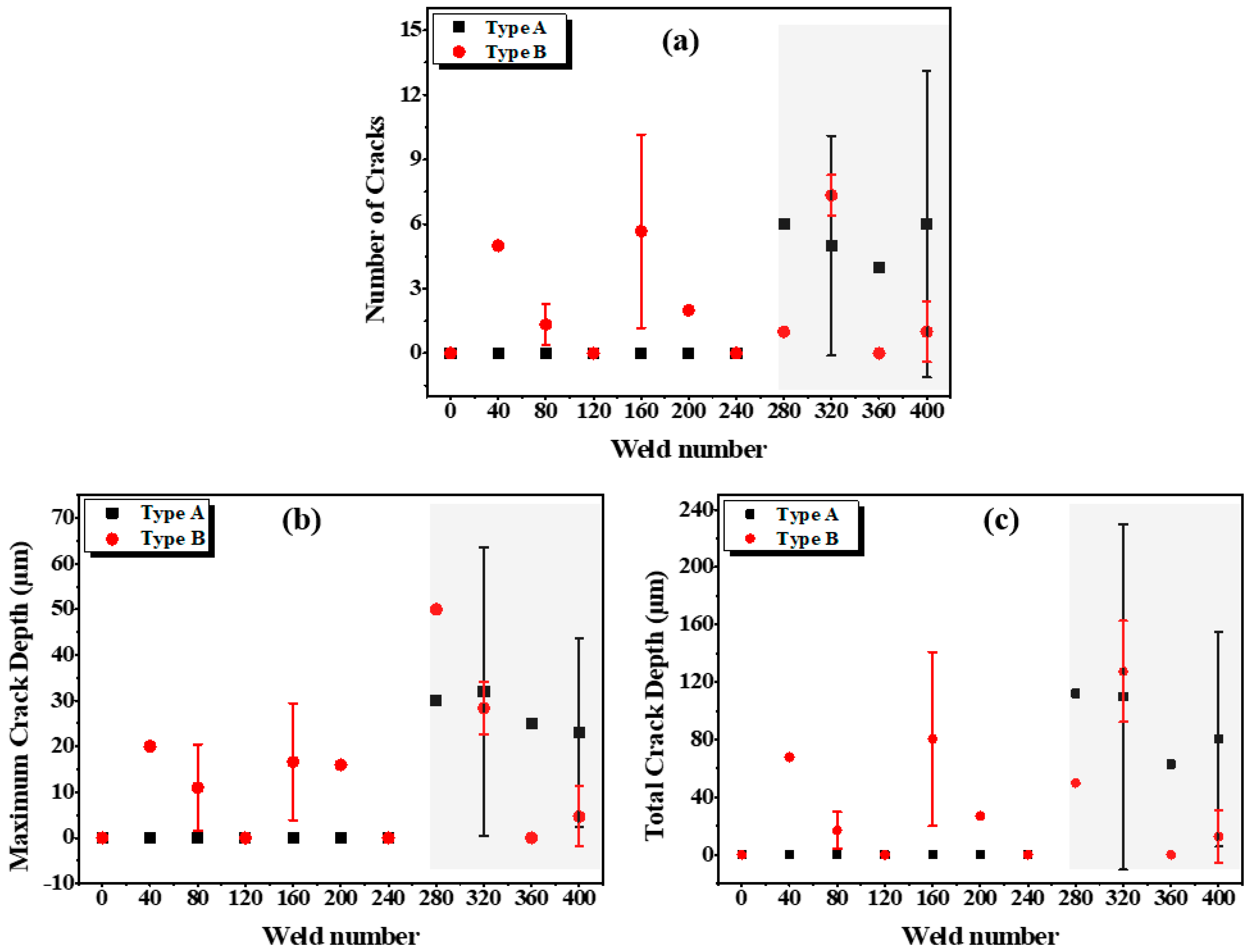
The LME cracks (type A and type B) formed in the uncoated steel joints were analyzed as a function of the number of welds in the consecutive welding. Three welds were analyzed per condition, and the average values for the number of cracks, total crack depth, and maximum crack depth were determined. These results are presented in Figure 13a–c. It is observed that the timing of crack formation in the consecutive welding varied depending on the specific location within the joint. It appears that type A cracks did not occur when the number of welds was less than 280. However, once the number of welds reached 280 or more, several cracks with a total length of approximately 30 μm were formed. In contrast, type B cracks began to appear after 40 welds. However, it was noted that the number and size of these cracks exhibited inconsistency as the number of welds increased. The variations in formation timing and characteristics between the types A and B cracks can be attributed to differences in stress levels in location and variations in the Zn content present on the electrode surface.
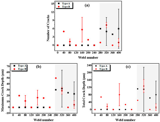
Figure 13.
LME crack analysis in the consecutive welding of the uncoated TRIP steel: (a) Number of cracks; (b) maximum crack depth; (c) total crack depth.
Due to the difficulty in analyzing the electrode surface during consecutive welding, the degree of alloying of the electrode was indirectly assessed by determining the Zn content on the surface of the joints [28]. Figure 14 shows the variation in Zn content in different locations on the surface of the uncoated TRIP steel welds as the number of welds increased. In Location A, it was observed that there was little or no detectable Zn on the surface when the number of welds was less than 280. However, beyond this point, the Zn content increased significantly. This finding is consistent with the analysis presented in Figure 13, which demonstrates that type A cracks began to occur when the number of welds reached 280 or more. It appears that the Zn and Cu content in the center of the electrode was not sufficient to trigger LME cracks before 280 welds. However, it is inferred that the threshold level for Zn-Cu alloying was surpassed after 280 welds, because of continuous alloying. In Location B, approximately 15 wt. % Zn was detected on the surface after 40 welds, and the Zn content displayed fluctuations as the number of welds increased. This observation aligns with the timing and characteristics of the type B LME cracks. In Location C, despite the presence of a Zn content similar to that of Location B, LME did not occur. This is because there is no contact between the electrode and the sheet in this location, leading to a much lower stress level.
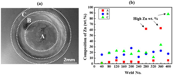
Figure 14.
Variation of Zn content on the uncoated steel surface: (a) weld surface showing the different locations and (b) Zn content with increasing number of welds.
4. Conclusions
Consecutive resistance spot welding was conducted to produce 400 consecutive welds in galvannealed and uncoated TRIP steels using the same pair of electrodes. The possibility of LME crack formation in the uncoated steel joints was investigated at regular intervals. The following key conclusions were drawn:
- (1)
- Small cracks were observed at the surface of the uncoated steel joints with a maximum length of about 30 µm and 50 µm in Location A (weld center) and Location B (shoulder of the weld), respectively, which were confirmed to be LME cracks.
- (2)
- During the consecutive welding, the electrode experienced metallurgical degradation or contamination with Zn (formation of different Cu-Zn phases) from the galvannealed steel. When welding the uncoated steel, owing to the heat generation at the electrode/sheet interface, the Cu-Zn phases melted, exposing the uncoated steel surface to liquid Zn and Cu, leading to LME cracking.
- (3)
- The occurrence and characteristics of the crack formation differed for each location as the number of welds increased due to the variation in Zn content. Type A cracks did not form when the number of welds was less than 280. However, several cracks with a total length of approximately 30 μm were formed between 280 and 400 welds. On the other hand, type B cracks began to appear after 40 welds. However, the number and size of these exhibited inconsistency as the number of welds increased.
Author Contributions
Conceptualization, J.W.K., K.M. and Y.-D.P.; Software, T.K.; Validation, T.K.; Formal analysis, S.M.M. and W.J.; Investigation, W.J. and D.-G.N.; Writing—original draft, J.W.K.; Writing—review & editing, S.M.M., K.M., D.-G.N., C.J. and Y.-D.P.; Funding acquisition, Y.-D.P. All authors have read and agreed to the published version of the manuscript.
Funding
This research was funded by Ministry of Trade, Industry & Energy, Korea (20012196) and MSIT (Ministry of Science and ICT), Korea (IITP-2023-2020-0-01791).
Data Availability Statement
Not applicable.
Acknowledgments
This work was supported by the Competency Development Program for Industry Specialists, and the Technology Innovation Program (Alchemist Project, 20012196, Al based supercritical materials discovery) funded by the Ministry of Trade, Industry & Energy, Korea and the MSIT (Ministry of Science and ICT), Korea, under the Grand Information Technology Research Center support program (IITP-2023-2020-0-01791) supervised by the IITP (Institute for Information & communications Technology Planning & Evaluation).
Conflicts of Interest
The authors declare no conflict of interest.
References
- Kim, Y.-M.; Hwang, I.; Cheon, J. Recent Research Trend of Resistance Spot Welding Quality Monitoring Technology in Korea. J. Weld. Join. 2023, 41, 90–99. [Google Scholar] [CrossRef]
- Soomro, I.A.; Pedapati, S.R.; Awang, M. A review of advances in resistance spot welding of automotive sheet steels: Emerging methods to improve joint mechanical performance. Int. J. Adv. Manuf. Technol. 2022, 118, 1335–1366. [Google Scholar] [CrossRef]
- Keeler, S.; Kimchi, M. Advanced High-Strength Steels Application Guidelines V5; WorldAutoSteel: Brussels, Belgium, 2015. [Google Scholar]
- Shome, M.; Tumuluru, M. Welding and Joining of Advanced High Strength Steels (AHSS); Woodhead Publishing: Sawston, UK, 2015. [Google Scholar]
- Shim, J.Y.; Park, M.W.; Kim, I.S. An Overview of Resistance Element Welding with Focus on Mechanical and Microstructure Joint and Optimization in Automotive Metal Joints. J. Weld. Join. 2023, 41, 37–48. [Google Scholar] [CrossRef]
- Mahmud, K.; Murugan, S.P.; Cho, Y.; Ji, C.; Nam, D.; Park, Y.-D. Geometrical degradation of electrode and liquid metal embrittlement cracking in resistance spot welding. J. Manuf. Process. 2021, 61, 334–348. [Google Scholar] [CrossRef]
- Park, G.; Uhm, S.; Lee, C. Review on the Resistance spot weldability of medium-Mn TRIP steel. J. Weld. Join. 2021, 39, 239–245. [Google Scholar] [CrossRef]
- Bhattacharya, D.; Cho, L.; Van Der Aa, E.; Pichler, A.; Pottore, N.; Ghassemi-Armaki, H.; Findley, K.; Speer, J. Influence of the starting microstructure of an advanced high strength steel on the characteristics of Zn-Assisted liquid metal embrittlement. Mater. Sci. Eng. A 2021, 804, 140391. [Google Scholar] [CrossRef]
- Christodoulou, P.I.; Kermanidis, A.T. A Combined Numerical–Analytical Study for Notched Fatigue Crack Initiation Assessment in TRIP Steel: A Local Strain and a Fracture Mechanics Approach. Metals 2023, 13, 1652. [Google Scholar] [CrossRef]
- Marder, A.R. The metallurgy of zinc-coated steel. Prog. Mater. Sci. 2000, 45, 191–271. [Google Scholar] [CrossRef]
- Tumuluru, M. The effect of coatings on the resistance spot welding behavior of 780 MPa dual-phase steel. Weld. J. 2007, 86, 161. [Google Scholar]
- Razmpoosh, M.H.; Biro, E.; Chen, D.L.; Goodwin, F.; Zhou, Y. Liquid metal embrittlement in laser lap joining of TWIP and medium-manganese TRIP steel: The role of stress and grain boundaries. Mater. Charact. 2018, 145, 627–633. [Google Scholar] [CrossRef]
- DiGiovanni, C.; Biro, E.; Zhou, N.Y. Impact of liquid metal embrittlement cracks on resistance spot weld static strength. Sci. Technol. Weld. Join. 2019, 24, 218–224. [Google Scholar] [CrossRef]
- Jin, W.; Lalachan, A.; Murugan, S.P.; Ji, C. Effect of Process Parameters and Nugget Growth Rate on Liquid Metal Embrittlement (LME) Cracking in the Resistance Spot Welding of Zinc-Coated Steels. J. Weld. Join. 2022, 40, 464–477. [Google Scholar] [CrossRef]
- Yang, K.; Meschut, G.; Seitz, G.; Biegler, M.; Rethmeier, M. The Identification of a New Liquid Metal Embrittlement (LME) Type in Resistance Spot Welding of Advanced High− Strength Steels on Reduced Flange Widths. Metals 2023, 13, 1754. [Google Scholar] [CrossRef]
- van der Aa, E.; Rana, R. Optimization of Hot Forming Temperature to Minimize Liquid Metal Embrittlement Induced Cracking in Resistance Spot Welded Zinc-Coated Medium Manganese Steel. Steel Res. Int. 2023, 2300045. [Google Scholar] [CrossRef]
- DiGiovanni, C.; He, L.; Pistek, U.; Goodwin, F.; Biro, E.; Zhou, N. Role of spot weld electrode geometry on liquid metal embrittlement crack development. J. Manuf. Process. 2020, 49, 1–9. [Google Scholar] [CrossRef]
- DiGiovanni, C.; Kalashami, A.G.; Goodwin, F.; Biro, E.; Zhou, N. Occurrence of sub-critical heat affected zone liquid metal embrittlement in joining of advanced high strength steel. J. Mater. Process. Technol. 2021, 288, 116917. [Google Scholar] [CrossRef]
- Murugan, S.P.; Mahmud, K.; Ji, C.; Jo, I.; Park, Y.-D. Critical design parameters of the electrode for liquid metal embrittlement cracking in resistance spot welding. Weld. World 2019, 63, 1613–1632. [Google Scholar] [CrossRef]
- Tolf, E.; Hedegård, J.; Melander, A. Surface breaking cracks in resistance spot welds of dual phase steels with electrogalvanised and hot dip zinc coating. Sci. Technol. Weld. Join. 2013, 18, 25–31. [Google Scholar] [CrossRef]
- Society, A.W. Recommended Practices for Test Methods for Evaluating the Resistance Spot Welding Behavior of Automotive Sheet Steel Materials; American Welding Society Florida: Doral, FL, USA, 2002. [Google Scholar]
- Murugan, S.; Vijayan, V.; Ji, C.; Park, Y. Four types of LME cracks in RSW of Zn-coated AHSS. Weld J. 2020, 99, 75s–92s. [Google Scholar] [CrossRef]
- Sage, D.; Fink, C. Understanding temperature and dwell time dependence of liquid metal embrittlement in austenitic stainless steel by liquid zinc and copper. Materialia 2022, 24, 101502. [Google Scholar] [CrossRef]
- Razmpoosh, M.; Macwan, A.; Goodwin, F.; Biro, E.; Zhou, Y. Role of random and coincidence site lattice grain boundaries in liquid metal embrittlement of iron (FCC)-Zn couple. Metall. Mater. Trans. A 2020, 51, 3938–3944. [Google Scholar] [CrossRef]
- Lee, S.-J.; Shin, S.E.; Ushioda, K.; Fujii, H. Microstructure, mechanical properties, and damping capacity in stir zone after friction stir welding of Fe–17Mn damping alloy. J. Alloys Compd. 2019, 803, 1155–1167. [Google Scholar] [CrossRef]
- Okamoto, H.; Massalski, T. Binary Alloy Phase Diagrams; ASM International: Materials Park, OH, USA, 1990; Volume 12. [Google Scholar]
- DiGiovanni, C.; Kalashami, A.G.; Biro, E.; Zhou, N. Liquid metal embrittlement transport mechanism in the Fe/Zn system: Stress-assisted diffusion. Materialia 2021, 18, 101153. [Google Scholar] [CrossRef]
- Kondo, M.; Konishi, T.; Nomura, K.; Kokawa, H. Degradation mechanism of electrode tip during alternate resistance spot welding of zinc coated and uncoated steel sheets. Sci. Technol. Weld. Join. 2010, 15, 76–80. [Google Scholar] [CrossRef]


Disclaimer/Publisher’s Note: The statements, opinions and data contained in all publications are solely those of the individual author(s) and contributor(s) and not of MDPI and/or the editor(s). MDPI and/or the editor(s) disclaim responsibility for any injury to people or property resulting from any ideas, methods, instructions or products referred to in the content. |
© 2023 by the authors. Licensee MDPI, Basel, Switzerland. This article is an open access article distributed under the terms and conditions of the Creative Commons Attribution (CC BY) license (https://creativecommons.org/licenses/by/4.0/).