Article

Study of Machined Surface Quality of AZ31B Magnesium Alloy by End Milling

1
Graduate School of Natural Science and Technology, Okayama University, 3-1-1 Tsushima-naka, Okayama 700-8530, Japan
2
School of Mechanical Engineering, Taiyuan University of Science and Technology, Taiyuan 030024, China
3
Upgrading Office of Modern College of Humanities and Sciences of Shanxi Normal University, Linfen 041000, China
*
Author to whom correspondence should be addressed.
Metals 2023, 13(10), 1712; https://doi.org/10.3390/met13101712
Submission received: 19 September 2023 / Revised: 1 October 2023 / Accepted: 6 October 2023 / Published: 8 October 2023
(This article belongs to the Section Metal Casting, Forming and Heat Treatment)

Abstract

:
Magnesium alloys are lightweight structural materials with excellent machinability. However, further development is seriously limited by their low strength and poor formability. Therefore, further decreasing the surface residual stress of the frame by post-process treatment is a key issue, such as for reducing the subsequent deformation due to the residual stress, improving the machining accuracy and corrosion resistance of the magnesium alloy frame products, and extending the service life of the magnesium alloy frame products. Using AZ31B magnesium alloy as the experimental subject, and by exploring the effects of milling parameters on the surface quality of frame parts, this study shows that the surface residual compressive stress, hardness, and roughness of frame parts decreased with the increasing of the milling speed and increased as the depth of cut and the feed per tooth increased. Using cutting fluid in the milling process can decrease the surface residual stress and roughness of the frame parts but increase the surface hardness. In accordance with the experimental results and analysis, the main reason affecting the residual stress on the surface layer of frame components is the thermal elastoplastic problem caused by thermal mechanical coupling during the milling process, resulting in varying stress states on the workpiece’s surface. The primary contributors to hardness are the work-hardening effect induced by milling forces and the thermal-softening effect of milling temperatures, which either augment or diminish the workpiece’s surface hardness. Furthermore, the primary factor impacting surface roughness is the magnitude of cutting forces. Excessive cutting forces lead to the ploughing phenomenon or tool vibrations, thereby causing varying degrees of surface roughness on the workpiece. Meanwhile, the influence of stress-relief annealing or cryogenic treatment on surface residual stress and hardness after the milling of the frame parts was researched. It shows that within the selected milling parameters, both stress-relief annealing and cryogenic treatment can reduce the surface residual stress and homogenize the residual stress distribution of frame parts. Stress-relief annealing leads to a reduction in the hardness of the machined surface, and the hardness of the machined surface increases slightly under cryogenic treatment. The effects of the two post-processing methods on surface quality vary, and in practical production, a rational selection can be made according to the different processing requirements to achieve the optimal standards.

1. Introduction

Magnesium alloy is a lightweight metal that is recyclable and possesses excellent machinability capabilities. Frame parts made of magnesium alloy have the characteristics of light weight and high structural utilization rate [1]. Magnesium alloys find application in a wide range of applications such as laptop cases, mobile outer cases, aerospace structural components, large cabins, telescope cases, and aircraft radar casings [2,3]. Depending on the application and stress state, the residual stresses in the workpiece can be desirable or undesirable. For example, compressive residual stresses improve the fatigue strength, while tensile residual stresses reduce the resistance against fatigue. However, any type of residual stresses have a destructive effect on the dimensional stability of the workpiece. Typically, in the scope and application of precise components, they are required to be free from possible residual stresses; on the other hand, these components are mainly produced by machining processes. Therefore, the parameters in the machining process of the precise components should be determined in a way that the final components are as free from residual stresses as possible [4]. In the milling process of frame parts, the mass and stiffness of frame parts decreases constantly with the continuous separation of chips, which also leads to the high material removal rate [5]. Meanwhile, the coupled thermo-mechanical stress in the milling process leads to the serious non-uniform elastic-plastic deformation of frame parts [6]. It will also cause deformation of the frame in the follow-up usage process [7]. In addition, the hardness and surface roughness are the key factors affecting the structural stability, corrosion performance, and fatigue strength [8,9].
Annealing treatment can improve the processability of magnesium alloy by increasing the temperature to boost the material energy system, refine grain size, generate static recrystallization, and relieve or decrease the residual stress, composition heterogeneity, and the instability of microstructure [10]. Cryogenic treatment is a technique wherein materials are processed at about liquid-nitrogen temperatures for a certain duration. Cryogenic environments can change the residual stress state and enhance the impact resistance and fatigue characteristics [11,12]. Therefore, by exploring the influence of milling parameters on the surface quality of frame parts, the surface integrity of frame parts is improved and the machining deformation is reduced. A key issue is to further decrease the surface residual stress of the frame by post-process treatment, such as by reducing the subsequent deformation due to the residual stress, improving the machining accuracy and corrosion resistance of the magnesium alloy frame products, and extending the service life of the magnesium alloy frame products.
However, some studies have been conducted on the residual stress of milled frame parts, but there are few studies on the cryogenic treatment and stress-relief annealing of magnesium alloys in recent years. Outeiro et al. [13] conducted orthogonal cutting tests on Mg alloy AZ31B-O disks and found that surface residual compressive stress increased as cutting depth, cutting speed, and tool cutting edge radius increased, and decreased as the tool rake angle increased. Moreover, the corrosion resistance of the workpiece was enhanced by improving the surface integrity. Li et al. [14] used different milling depths and feed rates to mill rectangular Al2024-T3 aluminum alloy and proved that forming smaller magnitudes of surface and sub-surface residual stress would obtain thin-walled parts with controllable distortion. Furthermore, by obtaining the shallow layer profile of residual stress and reducing the difference between the maximum surface and subsurface residual stress as much as possible, a smaller machining distortion of the thin-walled part will be generated. Zhou et al. [15] studied milling experiments on 5083 Al-Mg alloy thin-walled parts and concluded that the main influencing factor of milling force and machining deformation is milling depth, and the main influencing factor of surface roughness of thin-walled parts is the feed per tooth. In addition, they obtained high-precision empirical equations of milling force and surface roughness. Wang et al. [16] conducted face milling experiments on AZ31B magnesium alloy with different milling parameters and revealed that the surface residual compressive stress decreased as the milling speed increased, and increased as the milling depth and the feed per tooth increased. The range method was used to obtain the primary and secondary relationship of the factors of milling parameters on the surface residual stress as follows: milling speed, milling depth, feed per tooth, and cooling mode. Lian Yong et al. [17] presented that homogenization annealing can homogenize the residual stress distribution and reduce the maximum residual stress of the magnesium alloy plate by comparing the residual stress before and after annealing a ME21 magnesium alloy. Niu et al. [18] studied the optimum parameters of cryogenic treatment to reduce the residual stress of 2A12 aluminum alloy, and the results showed that the residual stresses under cryogenic treatment with the optimized parameters were decreased by up to 93%. Marwan et al. [19] studied the effect of cryogenic treatment on aluminum alloy AA6061, and the results shows a significant increase in hardness, tensile strength, and yield stress after cryogenic processing.
Scholars at home and abroad primarily focus on studying machining parameters, while also separately investigating the effects of different temperatures and holding time parameters in annealing and cryogenic treatment on surface quality. There have been no articles that collectively study milling parameters and post-processing methods. In this paper, we first study the impact of machining process parameters on the surface quality of milled magnesium alloy components. Subsequently, using stress-relief annealing and cryogenic treatment, we further investigate the influence of post-processing techniques on the residual stress and surface hardness of the framework components, aiming to achieve the desired surface quality of the machined components. The study focuses on magnesium alloy framework components, and experimental validation demonstrates a significant reduction in the residual stress in the framework components by improving the machining parameters and incorporating post-processing methods. Furthermore, the combination of different milling parameters and post-processing techniques enables the attainment of diverse surface quality requirements, thereby offering crucial guidance for the practical production of framework products.

2. Experimental Procedure

2.1. Experimental Material
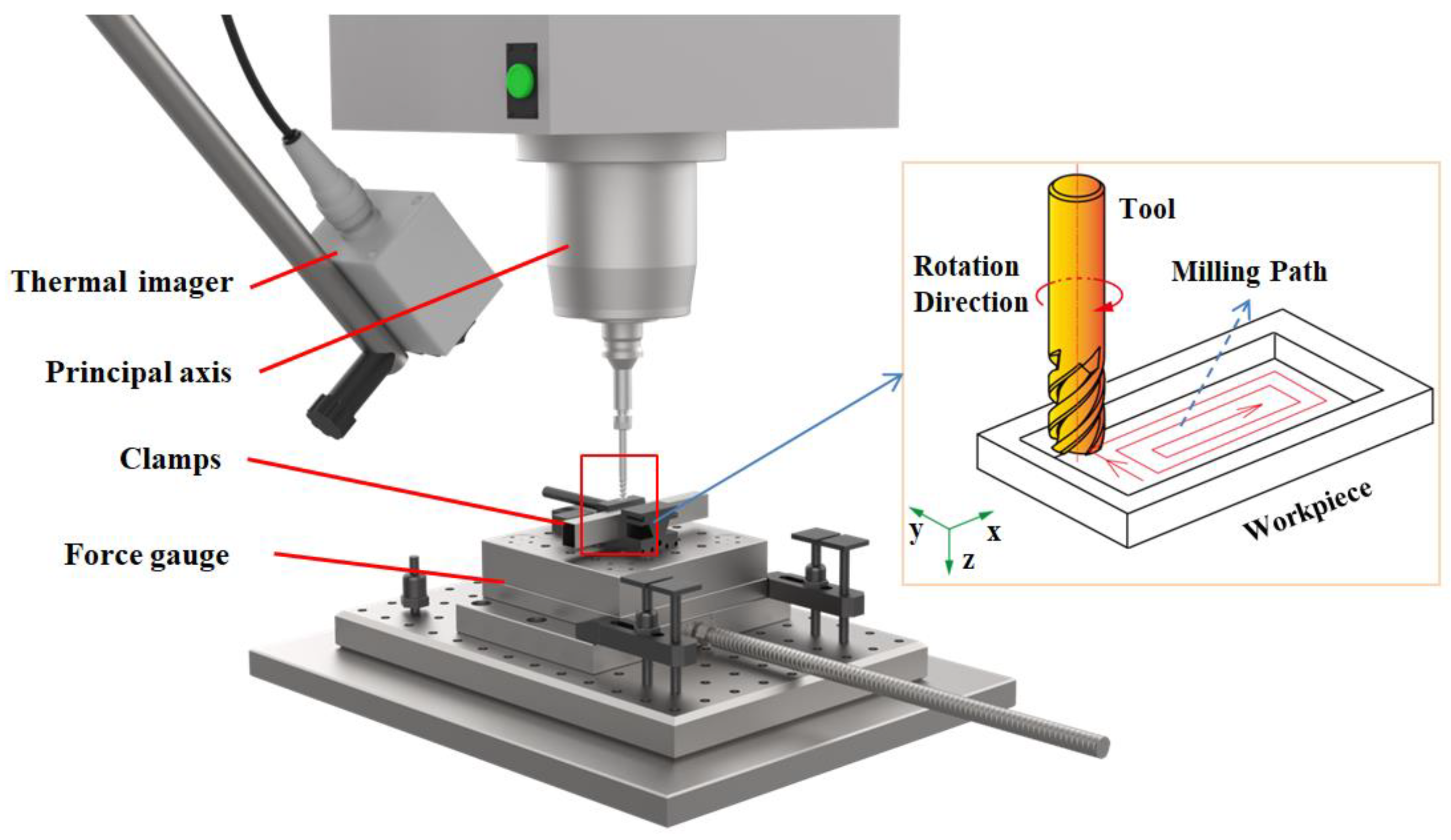
We used a rolled AZ31B magnesium alloy plate as the test material, with a size of 200 mm × 50 mm × 10 mm; its chemical composition is shown in Table 1, and the mechanical performance parameters of the material are shown in Table 2. The experimental materials were purchased from Hebi Magnesium Tu Technology Co., Ltd., Hebi, China. The chemical composition and mechanical performance parameters of the materials in Table 1 and Table 2 were provided by the company. The milling tool used was a 3-blade vertical milling cutter made of hard alloy YG8 tungsten carbide. The diameter of the end mill was 10 mm, the rake angle was 10°, the clearance angle was 10°, the helix angle was 45°, the blade length was 25 mm, and the total tool length was 75 mm, without coating.

2.2. Milling Test

The GX600 CNC Vertical Mill Center was used to mill the magnesium alloy plates, and the milling process is shown in Figure 1. The tool path strategy adapted the contour strategy from the outside to the inside as shown in Figure 1, which produced the least amount of deformation. The surface roughness of the magnesium alloy frame parts after milling was measured using a JB-4C surface roughness tester. The measuring needle had a tip radius of 0.1 mm. It traversed a distance of 2.5 mm on the surface of the frame member each time, in the same direction as the milling. Seven samples were taken from different positions on the workpiece surface, with each position being measured five times. The overall average value was used to represent the surface roughness of the workpiece. A Proto i-XRD diffractometer was used to measure the surface residual stress of magnesium alloy plates after machining. The distribution of the measuring points of the machined workpiece is shown in Figure 2. We took 12 points on each measurement line, respectively, for a total of 36 points. The average value of the residual stress of the 36 test points was taken as the final test result. The wall thickness of the machined workpieces was 5 mm, and the web thickness varied according to the milling depth. The X-ray diffraction parameters employed in the measurements are shown in Table 3. For general materials, the penetration depth of the X-ray was within 10–30 μm, and the direction of the measured residual stress was consistent with the milling direction. A MC010 micro-hardness tester was used to test the surface hardness of the magnesium alloy plate after machining (loading load was 0.098 N, loading time was 10 s). The MC010 micro-hardness tester used a Vickers indenter, which had a diamond shaped tip with a sharp angle of 136 degrees.

2.3. Heat Treatment Test

Stress-relief annealing for the milled magnesium alloy frame parts was conducted using a box atmosphere furnace. The cryogenic treatment of the milled magnesium alloy frame parts was carried out by a low temperature treatment chamber, as shown in Figure 3. The influences of the milling parameters on the surface quality of the workpieces were explored through the milling test. The influence of annealing on the surface residual stress and hardness were explored through milling and stress-relief annealing tests. The milling parameters are shown in Table 4. The milling was performed on three samples per parameters set. The annealing temperature used in the stress-relief annealing test was set at 200 °C, and the annealing time was 0.5 h. The influence of the cryogenic treatment on the surface residual stress and hardness were explored through milling and cryogenic treatment tests. The milling parameters and the cryogenic treatment parameters are shown in Table 5. The cryogenic test adopted milling speeds of 100, 150, and 200 m/min, with the aim of comparing the changes in residual stress before and after the cryogenic treatment more clearly.

3. Experimental Results and Analysis

3.1. Analysis of the Influence of Milling Process and Stress-Relief Annealing Treatment on Surface Quality

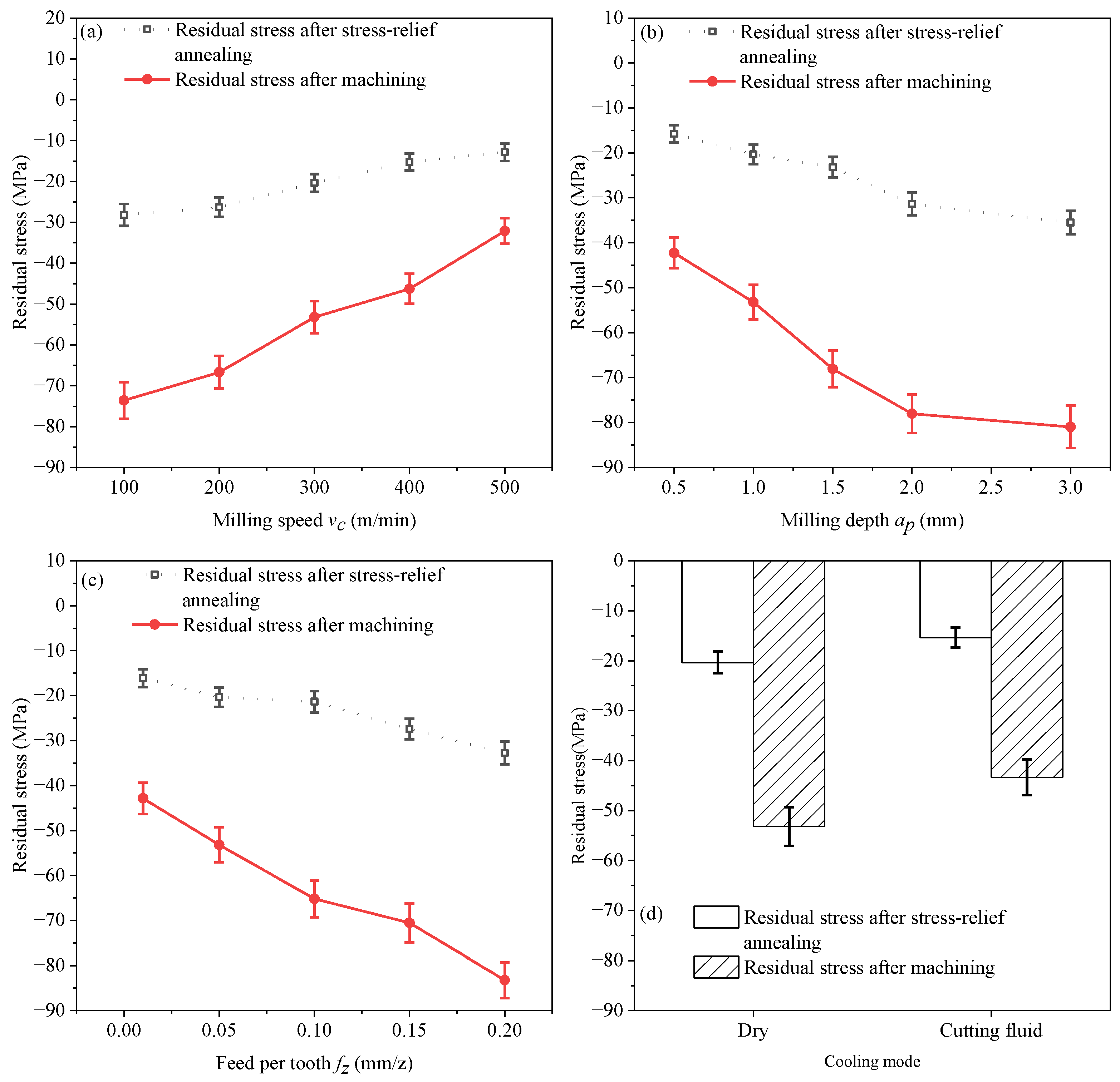
3.1.1. Surface Residual Stress Analysis

Figure 4 shows the surface residual stress of the workpieces after milling under the machining parameters shown in Table 4. The main reasons for the generation of cutting residual stress include the mechanical stress plastic deformation effect, the thermal stress plastic deformation effect, and local microstructure transformation of the surface. Variation in the residual stress is a coupled thermo-mechanical thermo-elasto-plastic problem [20]. The extrusion of the milling cutter on the surface of the magnesium alloy during the milling process causes the tensile plastic deformation of the surface metal. It triggers the ‘mechanical stress plastic deformation effect’, generating residual compressive stress on the surface of the frame parts. The heat generated in the rake–chip zone and flank–workpiece zone during milling triggers the ‘thermal stress plastic deformation effect’, resulting in residual tensile stress on the surface of the frame parts [21]. Low-speed milling leads to higher milling forces. The extrusion of the milling cutter on the surface of the magnesium alloy causes the tensile plastic deformation of the metal of the surface layer, and the ‘mechanical stress plastic deformation effect’ dominates the influence on the surface residual stress of the frame parts. The surface of frame parts is manifested as residual compressive stress. With the increase in the milling speed, the friction between the milling cutter and the chips as well as the surface of the frame parts increases, the milling temperature increases [22], the friction coefficient between the cutter edge and the workpiece decreases, and the thermal softening effect of the magnesium alloy increases. The thermal softening is greater than the work hardening of the magnesium alloy [23]. The milling force decreases, and the residual compressive stress on the surface of the frame parts also decreases; furthermore, the surface layer temperature of the workpiece is higher than the core temperature, which enhances the ‘thermal stress plastic deformation effect’. This effect results in residual tensile stress occurring on the frame parts after cooling. Thus, it can be observed from Figure 4a that the residual compressive stress of the frame parts gradually decreases as the milling speed increases within the selected milling parameters.
According to Figure 4b,c, within the selected milling test parameters, the milling thickness and the contact area between the milling cutter and the magnesium alloy plate increase with the increase in the milling depth and the feed per tooth, and the milling force increases, which enhances the “mechanical stress plastic deformation effect”. Therefore, the residual compressive stress of the frame parts gradually increases.
The parameters used in the cooling method study experiment in Figure 4d are the milling speed of 300 m/min, the milling depth of 1 mm, and a feed rate of 0.05 mm/z. Figure 4d shows that the use of cutting fluid can reduce the residual stress of the workpiece during the milling process. This is because cutting fluid lubricates the shear zone and then reduces the friction between the cutter edge and the workpiece [24]. The milling force decreases, which weakens the “mechanical stress plastic deformation effect”. Therefore, using cutting fluid can reduce the residual compressive stress.
The error bar in Figure 4 represents the standard deviation of the residual stress sample data before and after stress relieving annealing. This value can indicate the relative dispersion of data to the population mean. The larger the standard deviation earned, the greater the fluctuation in the sample data is, and the more imbalanced the surface residual stress is distributed. The smaller the standard deviation earned, the smaller fluctuation in the sample data is, and the more uniform the surface residual stress is distributed. From Figure 4, it is shown that the surface residual stress of the frame parts is efficiently released after stress-relief annealing within the selected range of milling parameters. And the standard deviations of the surface residual stress of the frame parts after annealing are smaller than before. This indicates that stress-relief annealing can make the surface residual stress of the frame parts tend toward being evenly distributed.
Figure 4 shows that within the selected milling parameter range, when milling with the parameters of 500 m/min milling speed, 0.5 mm milling depth, a feed per tooth of 0.01 mm/z, and the addition of cutting fluid, the magnesium alloy plate can reach the status of the smallest residual stress. Stress-relief annealing can effectively reduce the residual stress.
Figure 5 shows the effect of stress-relief annealing on surface residual stress. The left vertical axis represents the difference between the surface residual stress of magnesium alloy plates after milling and the surface residual stress after stress-relief annealing treatment. The right vertical axis represents the ratio of the difference in residual stress of machined surface before and after annealing, which is the proportion of surface residual stress reduction. The horizontal axis corresponds to the 14 test pieces in Table 4. As shown in Figure 5, among the 14 test data, the difference in residual stress on the surface of the workpiece varies significantly, ranging from 19.31 to 50.52 MPa, with a variation ratio of 56.14% to 67.29%. This indicates that the stress relieving annealing treatment has a strong reduction effect on the residual stress on the surface of AZ31B magnesium alloy frame components.

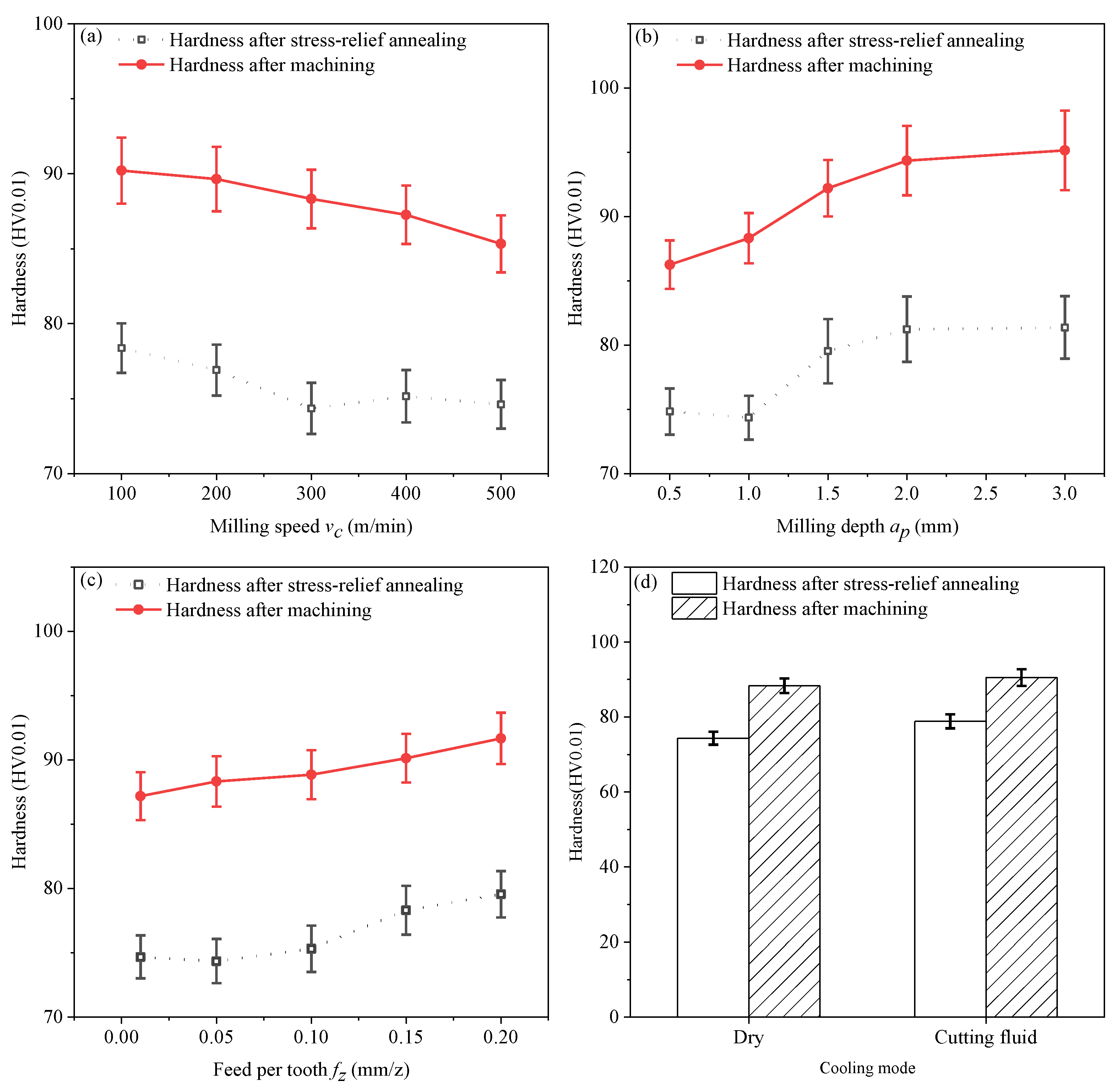
3.1.2. Surface Hardness Analysis

Figure 6 shows the hardness of machined surface under the machining parameters shown in Table 4. It can be seen from Figure 6a that the hardness of the machined surface decreases as the milling speed increases. This is due to the milling heat generated by the violent friction between the tool and the workpiece. The milling temperature increases with the increase in milling speed, while the milling force decreases within the selected range of milling parameters [16]. On one hand, the thermal softening effect of magnesium alloy reduces the degree of work hardening. On the other hand, the time of interaction between milling cutter and frame part decreases with the decrease in milling force, and the plastic deformation generated on the workpiece surface is inadequate, which reduces the work hardening effect of magnesium alloy [25].
According to Figure 6b,c, the extruding effect of the milling cutter on the surface of the workpiece increases with the increase in milling depth and feed per tooth, and the material removal volume increases, which enhances the work hardening effect. Therefore, the hardness of machined surface increases.
Figure 6d shows that using cutting fluid can enhance the hardness of machined surface. This is because using cutting fluid reduces cutting temperature, thereby enhancing the degree of surface work hardening. Figure 6 shows that within the selected milling parameter range, the maximum hardness of the magnesium alloy plate is achieved when milling at a milling speed of 100 m/min, a milling depth of 3 mm, a feed per tooth of 0.2 mm/z, and milling with the addition of cutting fluid. Stress-relief annealing can decrease the surface hardness of the magnesium alloy.
Figure 7 shows the effect of stress-relief annealing on surface hardness. As shown in Figure 7, the left vertical axis represents the difference between the surface hardness after milling of magnesium alloy plates and the surface hardness after stress relieving annealing treatment, while the right vertical axis represents the ratio of the difference between the surface hardness and the surface hardness after milling of magnesium alloy plates, which is the proportion of surface hardness reduction. As shown in Figure 6 and Figure 7, the difference in surface hardness values ranges between 10.7–13.97 HV0.01, and the relief ratio of surface hardness is in the range of approximately 12.54% to 15.82%. This indicates that the stress-relief annealing has a relief effect on surface hardness of AZ31B magnesium alloy frame parts.

3.1.3. Surface Roughness Analysis

Figure 8 shows the surface roughness of the workpieces after milling under the machining parameters shown in Table 4. It can be seen from Figure 8a that milling force and tool vibration amplitude decrease as the milling speed increases, resulting in a decrease in the surface roughness of the frame parts. Figure 8b shows that the axial milling force increases as the milling depth increases, and the chip layer is squeezed by the tool edge, generating a ploughing phenomenon, which results in an increase in the surface roughness of the frame parts [26]. Figure 8c shows that the plastic deformation of the workpiece and the tool vibration amplitude of the milling tool increase as the feed per tooth increases, which lead to the surface roughness of frame parts increasing [27]. Figure 8d shows that using cutting fluid results in a higher surface finish of the workpiece during the milling process. This is because the lubrication effect of the cutting fluid reduces the friction between the cutter edge and the workpiece, which decreases the surface roughness of frame parts.

3.2. Analysis of the Influence of Milling Process and Cryogenic Treatment on Surface Quality

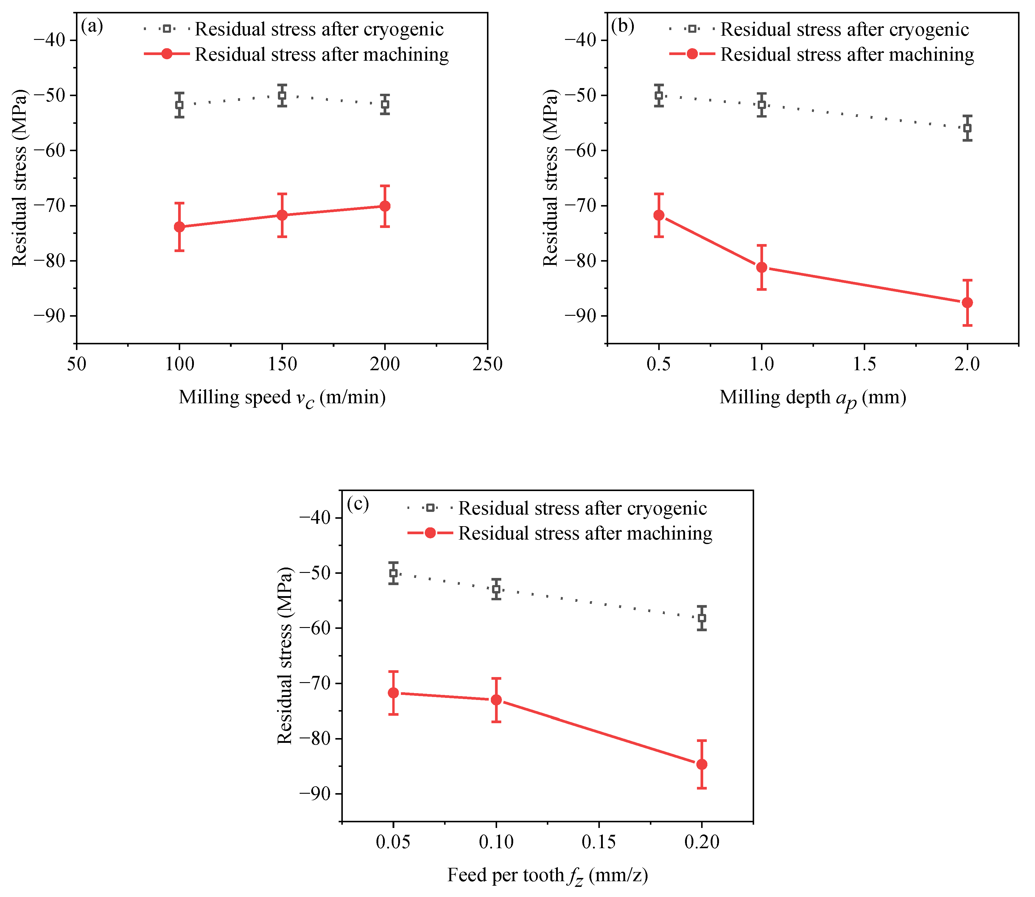
3.2.1. Surface Residual Stress Analysis

Figure 9 shows the surface residual stress of the workpieces after milling under the machining and cryogenic parameters shown in Table 5. It can be seen from Figure 9a that the residual compressive stress of frame parts gradually decreases as the milling speed increases within the selected milling parameters. According to Figure 9b,c, the residual compressive stress of the frame parts gradually increases with the increase in the milling depth and the feed per tooth. The variation trends of the surface residual stress in Figure 9 are similar to those in Figure 4. It is shown in Figure 9 that the surface residual stress of the frame parts was effectively released after the cryogenic treatment within the selected range of milling parameters. Magnesium alloys after milling exhibit high residual stress, with numerous lattice defects and high elastic energy within the grains, resulting in an unstable state. Cryogenic treatment provides energy to break this unstable state, allowing for atomic rearrangement, a decrease in solute atom solubility, and the precipitation of second phases at defect sites [18,28,29]. Consequently, the residual stress in the material is reduced. And the standard deviations of the surface residual stress of the frame parts after the cryogenic treatment are smaller than before. This indicates that cryogenic treatment can cause the surface residual stress of the frame parts to tend towards being evenly distributed. In addition, it can be seen that within the selected milling parameter range, the magnesium alloy plate has the lowest residual stresses at a milling speed of 150 m/min, a milling depth of 0.5 mm, and a feed per tooth of 0.05 mm/z.
Figure 10 shows the effect of the cryogenic treatment on the surface residual stress. The left vertical axis represents the difference value of the residual stress before and after the cryogenic treatment. The right vertical axis represents the relief ratio of the residual stress. The abscissa corresponds to the seven test pieces in Table 5. The difference value of the residual stress ranges between 18.47~31.65 MPa, and the relief ratio of the residual stress is in a range of about 26.35–36.29%. The maximum relief ratio was acquired in the condition in which the cryogenic temperature was −195 °C and the cryogenic time was 8 h. This indicates that lower cryogenic temperatures and longer cryogenic times have better relief effects on the surface residual stress of AZ31B magnesium alloy frame parts within the selected cryogenic parameters.

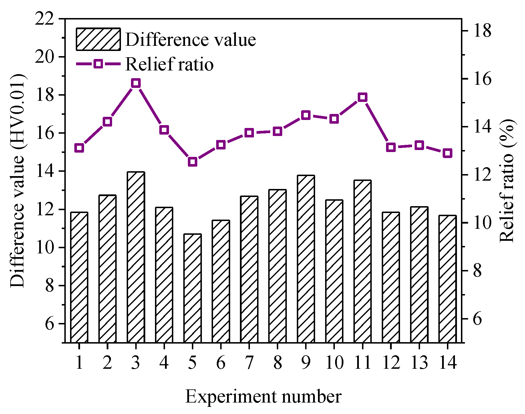
3.2.2. Surface Hardness Analysis

Figure 11 shows the hardness of the machined surface under the machining and cryogenic parameters shown in Table 5. It can be seen from Figure 11a that the hardness of the machined surface decreases as the milling speed increases. According to Figure 11b,c, the hardness of the machined surface gradually increases with the increase in the milling depth and the feed per tooth. The variation trends of the surface hardness in Figure 11 are similar to those in Figure 6. From Figure 11, within the selected milling parameters, the magnesium alloy plate has maximum surface hardness at a milling speed of 100 m/min, a milling depth of 2 mm, and a feed per tooth of 0.2 mm/z. Cryogenic treatment can effectively improve the surface hardness of the frame parts. This is because the cryogenic treatment process promotes grain refinement in the microstructure of the magnesium alloys. The degree of grain refinement is more pronounced after cryogenic treatment at −196 °C for 8 h [30]. Additionally, the precipitation of second phases in the microstructure of magnesium alloys contributes to an enhancement in hardness [18,29].
Figure 12 shows the effect of the cryogenic treatment on the surface hardness. The left vertical axis represents the difference value of the surface hardness before and after the cryogenic treatment. The right vertical axis represents the enhancement ratio of the surface hardness. From Figure 11 and Figure 12, it can be seen that the hardness of the machined surface slightly increased after the cryogenic treatment, with the increase in the surface hardness ranging from 3.11 to 6.0 HV0.01, and the increase rate ranging from 3.46% to 6.71%. This indicates that the cryogenic treatment can significantly improve the hardness of the machined surface of AZ31B magnesium alloy. The highest average increase in the hardness of the machined surface was observed when the cryogenic temperature was −195 °C and the cryogenic time was 8 h.

4. Conclusions

(1)
The law of the influence of the milling parameters on the surface quality of AZ31B magnesium alloy frame parts was obtained. The surface residual compressive stress, hardness, and roughness of the frame parts decreased with the increase in the milling speed and increased as the depth of cut and the feed per tooth increased. Using cutting fluid in the milling process can decrease the surface residual stress and roughness of the frame parts but increase the surface hardness.
(2)
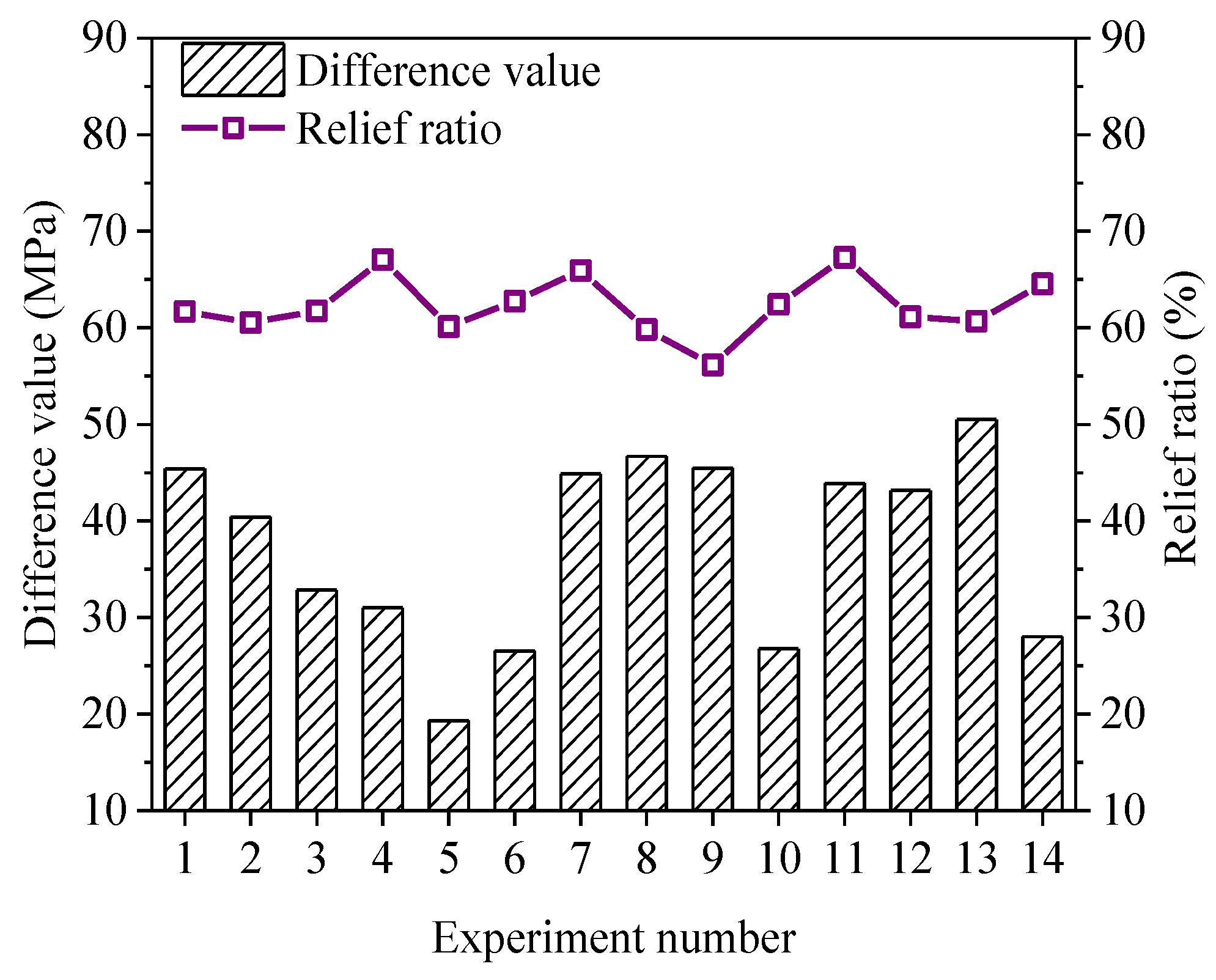
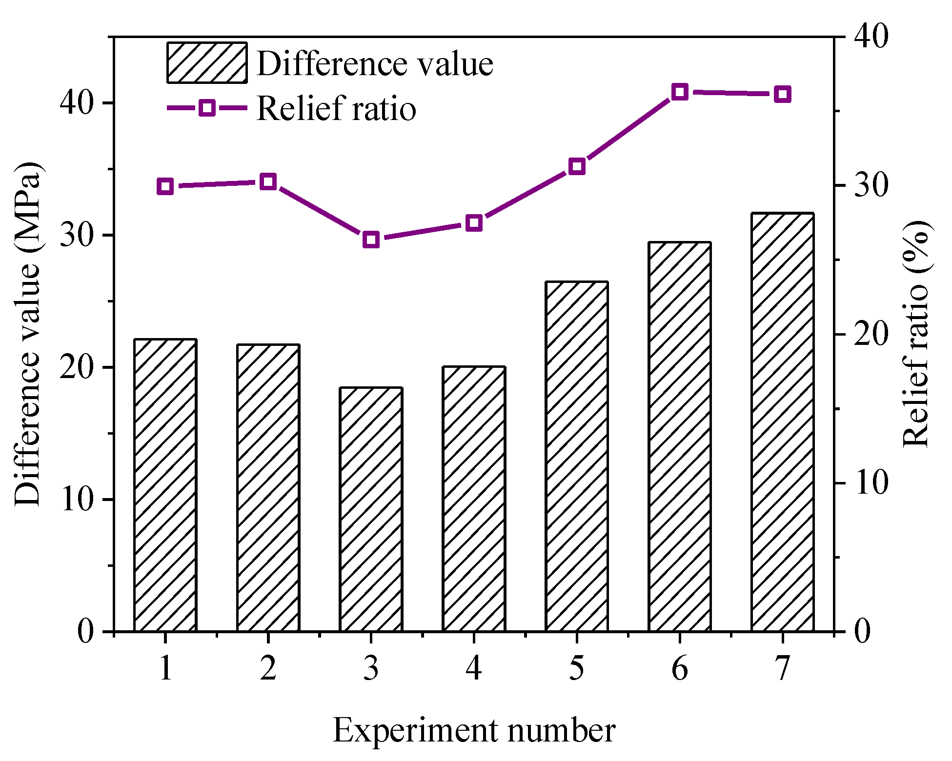
Both stress-relief annealing and cryogenic treatment can reduce the surface residual stress and homogenize the residual stress distribution of the frame parts within the selected milling parameters. The relief ratio of the residual stress on the milled magnesium alloy surface varied from 56.14% to 67.29% after the stress-relief annealing treatment. The relief ratio of the residual stress on the surface of the workpiece varied from 26.35% to 36.29% by the cryogenic treatment. Therefore, the stress-relief annealing treatment is more effective than the cryogenic treatment in relieving the surface residual stresses.
(3)
Stress-relief annealing resulted in a reduction in the hardness of the machined surface of the magnesium alloy in a range of about 12.54–15.82%. The cryogenic treatment enhanced the hardness of the machined surface of the magnesium alloy, and the increase rate ranged from 3.46% to 6.71%.
(4)
After comprehensively evaluating the various effects of milling parameters on surface residual stress and surface hardness, it can be concluded that different milling parameters and heat treatment methods can be combined to meet different machining requirements. Within the selected range of milling parameters, higher milling speed, such as 500 m/min, can effectively reduce surface residual stress, although it may cause a slight decrease in hardness. The implementation of cutting fluid can enhance the overall surface quality. A smaller cutting depth and feed per tooth, such as 0.5 mm and 0.01 mm/z, are advantageous for obtaining a smaller surface residual stress and surface roughness, which is beneficial for achieving good surface quality. If machining standards necessitate higher surface hardness, further processing of framework components can be conducted through cryogenic treatment. This not only enhances surface hardness but also mitigates surface residual stress. In the absence of stringent hardness requirements, stress-relief annealing can also be employed for the heat treatment of framework components, further reducing the residual surface stress in the workpiece.

Author Contributions

All authors have contributed to the conception and design of this study. Material preparation and data collection were conducted by R.W. Analysis and interpretation of the data were conducted by P.Z. and Y.H. The first draft of this manuscript was written by P.Z. and was audited by K.O. All authors have read and agreed to the published version of the manuscript.

Funding

This study was financially supported by the Shanxi Province Basic Research Program Joint Funding Project (No. TZLH20230818011), Taiyuan University of Science and Technology Graduate Education Innovation Project (SY2023038), National Natural Science Foundation of China (No. 52075357), and Shanxi Province patent promotion implementation subsidy special (No. 2019013).

Data Availability Statement

The datasets supporting the results of this article are included within the article.

Conflicts of Interest

The authors declare no competing interests.

References

  1. Zhu, Z.; Xi, X.; Xu, X.; Cai, Y. Digital Twin-driven machining process for thin-walled part manufacturing. J. Manuf. Syst. 2021, 59, 453–466. [Google Scholar] [CrossRef]
  2. Gobivel, K.; Sekar, K.V. Influence of cutting parameters on end milling of magnesium alloy AZ31B. Mater. Today Proc. 2022, 62, 933–937. [Google Scholar] [CrossRef]
  3. Hu, X.D.; Wu, G.J.; Liu, G.B.; Li, J. Key Technologies for CNC Milling of Thin walled Magnesium Alloy Parts. Met. Process. (Cold Work.) 2019, S2, 90–92. [Google Scholar]
  4. Khajehzadeh, M.; Boostanipour, O.; Razfar, M.R. Finite element simulation and experimental investigation of residual stresses in ultrasonic assisted turning. Ultrasonics 2022, 108, 106208. [Google Scholar] [CrossRef] [PubMed]
  5. Li, W.; Wang, L.; Yu, G.; Wang, D. Time-varying dynamics updating method for chatter prediction in thin-walled part milling process. Mech. Syst. Signal Process. 2021, 159, 107840. [Google Scholar] [CrossRef]
  6. Yue, C.; Zhang, J.; Liu, X.; Chen, Z.; Liang, S.Y.; Wang, L. Research progress on machining deformation of thin-walled parts during milling process. Chin. J. Aronaut. 2022, 43, 106–131. [Google Scholar]
  7. Waseem, A.; Ismail, L.; Steven, Y. Prediction and control of residual stress-based distortions in the machining of aerospace parts: A review. J. Manuf. Process. 2022, 76, 106–122. [Google Scholar] [CrossRef]
  8. Liang, X.; Liu, Z.; Wang, B.; Hou, X. Modeling of plastic deformation induced by thermo-mechanical stresses considering tool flank wear in high-speed machining Ti-6Al-4V. Int. J. Mech. Sci. 2018, 140, 1–12. [Google Scholar] [CrossRef]
  9. Wang, H.; Estrin, Y.; Fu, H.; Song, G.; Zúberová, Z. The effect of pre-processing and grain structure on the bio-corrosion and fatigue resistance of magnesium alloy AZ31. Wiley-VCH Verlag. 2007, 9, 967–972. [Google Scholar] [CrossRef]
  10. Ding, Y.-L.; Wang, J.-G.; Zhao, M.; Ju, D.-Y. Effect of annealing temperature on joints of diffusion bonded Mg/Al alloys. Trans. Nonferrous Met. Soc. China 2018, 28, 251–258. [Google Scholar] [CrossRef]
  11. Asl, K.M.; Tari, A.; Khomamizadeh, F. Effect of deep cryogenic treatment on microstructure, creep and wear behaviors of AZ91 magnesium alloy. Msea 2009, 523, 27–31. [Google Scholar] [CrossRef]
  12. Liu, Y.; Shao, S.; Xu, C.S.; Zeng, X.S.; Yang, X.J. Effect of cryogenic treatment on the microstructure and mechanical properties of Mg–1.5Zn–0.15Gd magnesium alloy. Msea 2013, 588, 76–81. [Google Scholar] [CrossRef]
  13. Jose, C.O.; António, C.B.; Maria, J.M. Residual Stresses Induced by Dry and Cryogenic Cooling during Machining of AZ31B Magnesium Alloy. Adv. Mat. Res. 2014, 3278, 658–663. [Google Scholar]
  14. Li, B.; Jiang, X.; Yang, J.; Liang, S.Y. Effects of depth of cut on the redistribution of residual stress and distortion during the milling of thin-walled part. J. Mater. Process Technol. 2015, 216, 223–233. [Google Scholar] [CrossRef]
  15. Zhou, K.; Jiao, X.L.; Zhang, H.; Sun, H. Numerical control milling experiment and optimization of 5083 aluminum magnesium alloy thin-walled parts. Equip. Manuf. Technol. 2018, 9, 116–120 + 127. [Google Scholar]
  16. Wang, R.J.; Du, M.X.; Zhang, P.C. The Effect of Milling Process Parameters on the Surface Quality of AZ31B Magnesium Alloy. Trans. Mater. Heat Treat. 2022, 43, 151–160. [Google Scholar]
  17. Lian, Y.; Ji, P.; Zhang, J.; Yuan, X.; Xu, W.; Zhao, Y.; Mo, J.; Zheng, L.; Dou, S. Effect of homogenization annealing on internal residual stress distribution and texture in ME21 magnesium alloy extruded plates. J. Magnes. Alloy 2019, 7, 186–192. [Google Scholar] [CrossRef]
  18. Niu, X.; Huang, Y.; Yan, X.; Chen, Z.; Yuan, R.; Zhang, H.; Tang, L. Optimization of Cryogenic Treatment Parameters for the Minimum Residual Stress. J. Mater. Eng. Perform. 2021, 30, 9038–9047. [Google Scholar] [CrossRef]
  19. Marwan, A.M.; Ali, H.A.; Jamal, J.D. Influence of cryogenic treatment on hardness, tensile properties, and microstructure of aluminum alloy AA6061. Mater. Today Proc. 2022, 60, 2157–2161. [Google Scholar] [CrossRef]
  20. Navas, V.G.; Gonzalo, O.; Bengoetxea, I. Effect of cutting parameters in the surface residual stresses generated by turning in AISI 4340 steel. Int. J. Mach. Tools Manuf. 2012, 61, 48–57. [Google Scholar] [CrossRef]
  21. Mahdi, M.; Zhang, L.C. Residual stresses in ground components caused by coupled thermal and mechanical plastic deformation. J. Mater. Process Technol. 1999, 95, 238–245. [Google Scholar] [CrossRef]
  22. Li, L.; Chang, H.; Wang, M.; Zuo, D.W.; He, L. Temperature measurement in high speed milling Ti6Al4V. Key Eng. Mater. 2004, 259–260, 804–808. [Google Scholar] [CrossRef]
  23. Wang, C.; Ding, F.; Tang, D.; Zheng, L.; Li, S.; Xie, Y. Modeling and simulation of the high-speed milling of hardened steel SKD11 (62 HRC) based on SHPB technology. Int. J. Mach. Tools Manuf. 2016, 108, 13–26. [Google Scholar] [CrossRef]
  24. Fan, L.; Yan, P.; Chen, S.Q.; Chen, H.; Jiao, L.; Qiu, T.Y.; Wang, X.B. Low temperature cutting performance and process parameter optimization of magnesium alloy. J. Harbin Inst. Technol. 2022, 54, 53–63 + 69. [Google Scholar]
  25. Sun, S.L.; Zhao, J.; Yuan, W.J.; Xi, W.; Zhao, C. GH4169 Study on Surface work hardening of GH4169 Nickel Base Superalloy. Tools Technol. 2016, 50, 24–27. [Google Scholar]
  26. Wojciechowski, S.; Krajewska-Śpiewak, J.; Maruda, R.; Krolczyk, G.; Nieslony, P.; Wieczorowski, M.; Gawlik, J. Study on ploughing phenomena in tool flank face—Workpiece interface including tool wear effect during ball-end milling. Tribol. Int. 2023, 181, 108313, ISSN 0301-679X. [Google Scholar] [CrossRef]
  27. Zhou, J.; Shu, L.S. Effect of high-speed milling parameters on surface roughness and residual stress of nickel based laser cladding alloy. Tools Technol. 2022, 56, 45–48. [Google Scholar]
  28. Tian, Z.Q.; Wei, K.X.; Wei, W.; Du, Q.B.; Hu, J. Microstructure and Mechanical Properties of Cryogenic Aluminum Silicon Alloy. Metal. Heat Treat. 2017, 42, 54–58. [Google Scholar]
  29. Huang, Y.; Yan, X.; Niu, X.; Chen, Q.; Yuan, R.; Zhang, H.; Yao, Y.; Fan, J. Effects of Deep and Shallow Cryogenic Treatment on Surface Residual Stress of 2A12 Aluminum Alloy Thick Plate. Hot Work. Technol. 2022, 51, 152–154 + 157. [Google Scholar] [CrossRef]
  30. Rao, C.; Zhou, M.; Lan, Y.; Xu, W. Effect of deep cryogenic treatment on microstructure and mechanical properties of AZ91 magnesium alloy. Light Alloy Fabr. Technol. 2021, 49, 66–71. [Google Scholar] [CrossRef]
Figure 1. Milling device.
Metals 13 01712 g001
Figure 2. Measuring point distribution diagram.
Metals 13 01712 g002
Figure 3. Low temperature treatment chamber.
Metals 13 01712 g003
Figure 4. Effect of milling parameters and stress-relief annealing on surface residual stresses. (a) Effect of milling speed and stress-relief annealing on surface residual stresses. (b) Effect of milling depth and stress-relief annealing on surface residual stresses. (c) Effect of the feed per tooth and stress-relief annealing on surface residual stresses. (d) Effect of cooling method and stress-relief annealing on surface residual stresses.
Metals 13 01712 g004
Figure 5. Effect of stress-relief annealing treatment on residual stress in the surface layer.
Metals 13 01712 g005
Figure 6. Effect of milling parameters and stress-relief annealing on surface hardness (a) Effect of milling speed and stress-relief annealing on surface hardness; (b) Effect of milling depth and stress-relief annealing on surface hardness; (c) Effect of the feed per tooth and stress-relief annealing on surface hardness; (d) Effect of cooling method and stress-relief annealing on surface hardness.
Metals 13 01712 g006
Figure 7. Effect of stress-relief annealing on surface hardness.
Metals 13 01712 g007
Figure 8. Effect of milling parameters on surface roughness. (a) Effect of milling speed on surface roughness; (b) effect of milling depth on surface roughness; (c) effect of the feed per tooth on surface roughness; (d) effect of cooling method on surface roughness.
Metals 13 01712 g008
Figure 9. Effect of milling parameters and cryogenic on surface residual stresses. (a) Effect of milling speed and cryogenic on surface residual stresses; (b) effect of milling depth and cryogenic on surface residual stresses; (c) effect of the feed per tooth and cryogenic on surface residual stresses.
Metals 13 01712 g009
Figure 10. Effect of cryogenic on surface residual stresses.
Metals 13 01712 g010
Figure 11. Effect of milling parameters and cryogenic on surface hardness. (a) effect of milling speed and cryogenic on surface hardness; (b) effect of milling depth and cryogenic on surface hardness; (c) effect of the feed per tooth and cryogenic on surface hardness.
Metals 13 01712 g011
Figure 12. Effect of cryogenic on surface hardness.
Metals 13 01712 g012
Table 1. Chemical composition of AZ31B magnesium alloy (mass fraction, %).
AlZnMnBeCuCaSiFeMg
3.190.810.3340.10.050.040.020.005Bal.
Table 2. Mechanical property parameters of AZ31B magnesium alloy.
Mechanical PropertySymbolUnitNumerical Value
Melting pointT°C630
Densityρg/cm31.77
Vickers hardnessHVHV0.0183
Strength limitσbMPa255
Yield limitσsMPa155
Elongation at breakσh-21%
Young’s modulusEGPa45
Compressive yield strengthσcyMPa110
Poisson’s ratioμ-0.35
Shear modulusGGPa17.0
Shear strengthσcMPa145
Specific heat capacityCpJ/kg/°C1013
Thermal conductivityλW/m/°C78.9
Table 3. X-ray diffraction parameters of residual stress of AZ31B magnesium alloy.
RadiationMn-kα
Voltage and current20 kV, 4 mA
Collimator diameter (mm)5
X-ray elastic(1/2) S2 = 29.32 × 10⁻⁶
constants (MPa−1)S1 = −6.59 × 10⁻⁶
Bragg angle 2θ (deg)151.06, (hkl) = (203)
Number of ψ angles30
Table 4. Milling parameters.
NumberMilling Speed
vc/m·min−1
Milling Depth
ap/mm
Feed Rate per Tooth
fz/mm·z−1
Cooling Mode
110010.05Dry
220010.05Dry
330010.05Dry
440010.05Dry
550010.05Dry
63000.50.05Dry
73001.50.05Dry
830020.05Dry
930030.05Dry
1030010.01Dry
1130010.1Dry
1230010.15Dry
1330010.2Dry
1430010.05Cutting fluid
Table 5. Milling and cryogenic parameters.
NumberMilling Speed, vc/m·min−1Milling Depth,
ap/mm
Feed Rate per Tooth,
fz/mm·z−1
Cryogenic Temperature,
T/°C
Cryogenic Time,
t/h
11000.50.05−1952
21500.50.05−1952
32000.50.05−1202
41500.50.1−1202
51500.50.2−1958
615010.05−1958
715020.05−1958
Disclaimer/Publisher’s Note: The statements, opinions and data contained in all publications are solely those of the individual author(s) and contributor(s) and not of MDPI and/or the editor(s). MDPI and/or the editor(s) disclaim responsibility for any injury to people or property resulting from any ideas, methods, instructions or products referred to in the content.

