Abstract
Laser powder bed fusion (L-PBF) is a novel process representing a possible solution for producing resistant parts using NiCrBSi hard-facing nickel alloys with complex geometry. Process parameters for more common alloys are explored with a standard Renishaw AM400 device (Renishaw, Wotton-under-Edge, UK) and an SLM Solution 250 device (SLM Solutions Group AG, Lübeck, Germany) modified with a baseplate preheated at high temperatures (300 °C and 500 °C). Laser remelting is also investigated in hopes of further improving material health. The origin of the main defects is studied. A lack of fusion is likely to be generated by spatters ejected from the melting pool while cracks are induced by the alloy’s lack of toughness. Using image analyses, those defects are quantified and correlated with processing parameters. Lack of fusion and total crack length decrease with an increase in baseplate’s preheating temperature. However, crack width increases with preheating temperature. Therefore, via a careful optimization of process parameters, samples with a surface density of 99% and narrow cracks are obtained.
1. Introduction
Self-fluxing alloys (SFAs) are commonly used as wear- and corrosion-resistant hard-facing coatings [1,2]. Several applications can be found, such as power generation (pumps and turbines), motorization (cylinders, pistons, and valves), mining (digging picks), drilling tools, or glass-forming moulds and cement works [3,4,5,6,7]. They are also an alternative to cobalt-based superalloys and hard chromium deposits [8,9,10,11]. Among those alloys, NiCrBSi alloys are the most studied [3]. They are hardened by three mechanisms: a solid solution of chromium, iron, and silicon in a nickel-rich matrix; the fine precipitation of Ni3Si; and hard phases such as chromium borides and carbides, nickel borides, and silicide [12,13,14].
Additive manufacturing (AM) is a novel category of processes that is capable of reducing the buy-to-fly ratio and production time while enabling parts with complex shapes [15]. Among AM processes, laser powder bed fusion (L-PBF) is the most studied for its capability to build near-net shape parts with a complex geometry [16]. However, some issues regarding process stability, reliability, and repeatability mainly dictated by process parameters are still unsolved [17].
In the nickel-based superalloy field, the L-PBF process is mainly used and studied with respect to weldable alloys such as alloy 718 or 625 [18,19,20]. Some studies explore non-weldable alloys, such as CM247LC [21,22,23,24,25,26,27,28,29,30,31,32], IN738LC [33,34,35,36,37], or IN939 [38,39]. However, the difficulties associated with cracking remain unresolved.
NiCrBSi alloys are mainly used as coatings. Furthermore, wear-resistant hard alloys are difficult to machine. Therefore, complex small parts made out of NiCrBSi are difficult to obtain using conventional methods. However, the production of NiCrBSi alloy parts using the L-PBF process might allow the construction of complex parts out of wear-resistant hard alloys. Despite these arguments, the production of NiCrBSi alloys by L-PBF is almost unstudied [40,41,42]. The few papers found throughout the literature mention, in one way or another, cracking issues. Furthermore, Shishkovsky et al. [40] recommend preheating the baseplate between 500 and 700 °C to reduce cracking. However, the relationships between material health and process parameters are not studied. It should be mentioned that the L-PBF production of NiCrBSi alloys is also studied by Shishkovsky et al. in the case of a metal matrix composite (MMC) with the addition of TiC [43] or WC [44] particles.
According to papers concerning the challenge of producing hard alloys such as M2 tool steel, a careful choice of process parameters and preheating the baseplate are the most used methods for reducing cracking [45,46]. Finally, despite the lack of consensus [47], adding a second laser path might reduce cracks [48,49,50,51].
This paper explores the processability of the NiCrBSi alloy using the L-PBF process. A commercial device is first used. Secondly, following the recommendations of Shishkovsky et al. [40], a modified device with a baseplate preheated up to 500 °C is also utilized. A broad range of process parameters is explored based on the parameters used for other nickel-based alloys (625, 718, and CM247LC). The influence of laser remelting on cracking behaviour is also studied. Finally, an image analysis protocol is established to separate and quantify the defects (lack of fusion, porosity, and cracks). The origin of cracks and lack of fusion are investigated. Finally, these defects are correlated with process parameters.
2. Materials and Methods
2.1. Material
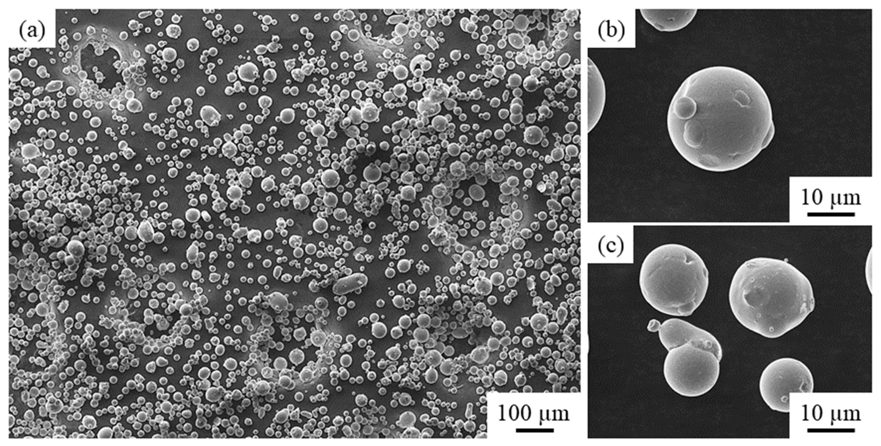
The NiCrBSi powder was custom-made via gas-atomization by manufacturer Aubert & Duval (Irun, Spain). In order to generate high hardness and wear resistance, the alloy contains a significant number of elements that are likely to generate hard phases (Table 1). The particle’s size distribution (D10 = 17 µm, D50 = 31 µm, and D90 = 47 µm) is measured using light diffusion and sieving following the ASTM B822 and the ISO 4497 [52]. According to the L-PBF device’s recommendations, the grain size of the powder is suitable. Finally, the purchased powder mainly exhibits a spherical shape (Figure 1).

Table 1.
Chemical composition of the NiCrBSi powder (wt. %).

Figure 1.
SEM micrographs of the purchased NiCrBSi powder: (a) general aspect; (b) and (c) show higher magnification with respect to particles.
2.2. LPB-F Production
For this study, two devices were used. The first is a Renishaw AM400 (Renishaw, Wotton-under-Edge, UK) equipped with a pulsed ytterbium fiber laser with a wavelength of 1070 nm and a maximum power of 400 W. The second one is an SLM Solution 250 (SLM Solutions Group AG, Lübeck, Germany) with a continuous ytterbium fiber laser with a similar wavelength and maximum power. In order to compare the used process parameters with different L-PBF devices and with the literature, laser speed “v” for the pulsed laser is calculated according to the following equation:
where “exp” denotes the exposure times in µs, “Pd” denotes the point distances, and “Vp” denotes the (virtual) speed between each point. “El” is the Lineic Energy, which is calculated using the following equation:
where “P” denotes the laser power. Finally, the volume energy density “VED” is calculated using the following equation:
where “Hd” denotes the hatch distance, and “t” denotes the layer thickness.
v = Pd/(exp + (Pd/Vp))
El = P/v
VED = P/(v × Hd × t)
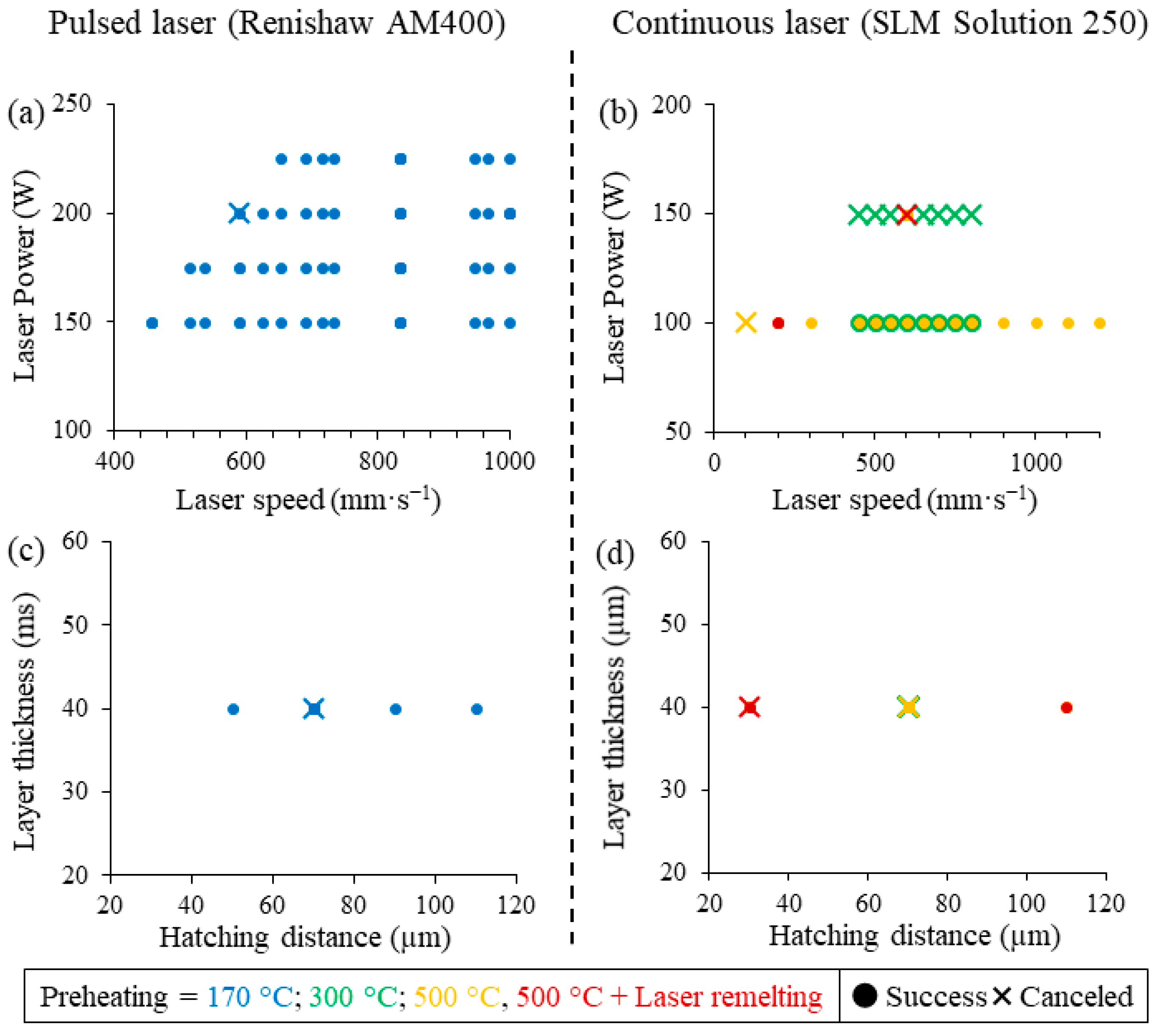
L-PBF production can be separated in 4 batches with different preheating temperatures or laser remelting (Figure 2):

Figure 2.
Summary of the different L-PBF productions. (a,c) Productions carried out on the Renishaw AM400 equipped with a pulsed laser. (b,d) Production carried out on the SLM Solutions 250 equipped with a continuous laser. Cross corresponds to cancelled samples during production.
- Standard L-PBF productions (Figure 2) were carried out using a Renishaw AM400 with a standard baseplate (250 × 250 mm) heated to 170 °C. A laser power of 150, 175, 200, and 225 W is used. Various exposure times between 20 and 140 µs and point distances between 20 and 140 µm are tested. According to several papers in the field of nickel-based superalloys produced with a Renishaw AM400 device [53,54,55,56,57,58,59], parameter sets leading to a linear energy lower than 0.15 J·mm−1 and greater than 0.35 J·mm−1 and a VED greater than 130 J·mm−3 are not tested. Finally, the hatch distance was kept at 70 µm, except for the four samples obtained with an Hd between 50 and 110 µm. In total, 75 samples (cubes of 13 × 14 × 15 mm3) out of 76 were built (Figure 2a,c).
- High-temperature L-PBF production and laser remelting exploration were conducted with a modified SLM Solution 250 device (continuous laser) on a small round baseplate (100 mm diameter). Two preheating temperatures were tested: 300 and 500 °C. For 300 °C (Figure 2), a laser power of 100 and 150 W was used, and the laser scanning speed varied between 450 and 800 mm·s−1. Hatch spacing was kept at 70 µm. In total, 8 out of 16 samples (cubes of 10 × 10 × 10 mm3) were built (Figure 2b,d).
- For 500 °C (Figure 2), according to results obtained at 300 °C, a laser power of 100 W was mainly used with a laser speed between 100 and 1200 mm·s−1. A laser power of 150 W and laser speed of 600 mm·s−1 were also tested. Hatch spacing varied from 30 to 110 µm for four samples, and it was kept at 70 µm for the rest of the production. In total, 19 out of 20 samples (cubes of 10 × 10 × 10 mm3) were built (Figure 2b,d)).
- Finally, four samples were produced with laser remelting (same parameters as the first laser path) on a baseplate preheated at 500 °C. Two samples were obtained with a laser power of 100 W, a laser speed of 200 mm·s−1, and a hatch spacing of 30 and 110 µm. Two other samples were constructed with a laser power of 150 W, a laser speed of 600 mm·s−1, and a hatch spacing of 30 and 110 µm. In total, 3 out of 4 samples (cubes of 10 × 10 × 10 mm3) were built. Those parameter sets are chosen for their capacity to produce a few cracks (Figure 2b,d)).
Finally, the layer’s thickness was kept at 40 µm. In order to reduce the experimental design, only the meander scanning strategy with a 67° rotation between each layer was explored. A focus diameter of 70 µm was used. Finally, the coordinate system comprised the height of the build following the build direction relative to the Z axis while the X and Y axes were used relative to the scanning plane.
2.3. Sample Preparation
Samples were separated from the baseplate by electric wire discharge. To prevent further crack propagation during preparation, samples were first mounted in room temperature curing epoxy resin. Metallography sample preparation was performed with a series of abrasive grinding SiC paper with decreasing coarseness to 4000 grit, followed by polishing with 3 and then 1 µm diamond particle suspensions. For high-magnification analyses (SEM; ZEISS, Paris, France), a final polishing step with OPS (silica suspension of 0.25 µm) was used. Finally, the microstructure was revealed via chemical etching with Marble’s reagent (20 mL of HCl, 4 g of CuSO4, and 20 mL of H2O) after 30 s exposure time. Due to the chemical etching reaction with the alloy, the final polishing and chemical etching steps were not conducted for defect quantification.
2.4. Defects Detection and Analysis
Defects are observed using an optical microscope PMG3 from Olympus (Olympus France 117 SAS, Rungis, France). Further analyses are carried out via X-ray tomography with an Easytom X-ray tomograph (RX solutions, Annecy, France) on 5 × 5 mm2 samples. Then, 1440 slices were taken with a step of 0.1° and an acceleration voltage of 150 kV. Finally, the voxel lateral size was calculated at 5 µm. Additional analyses were conducted with a ZEISS EVO10 HD15 (ZEISS, Paris, France) Scanning Electron Microscope (SEM). An acceleration voltage of 15 kV and a working distance of 10 mm were used.
2.5. Defects Quantification
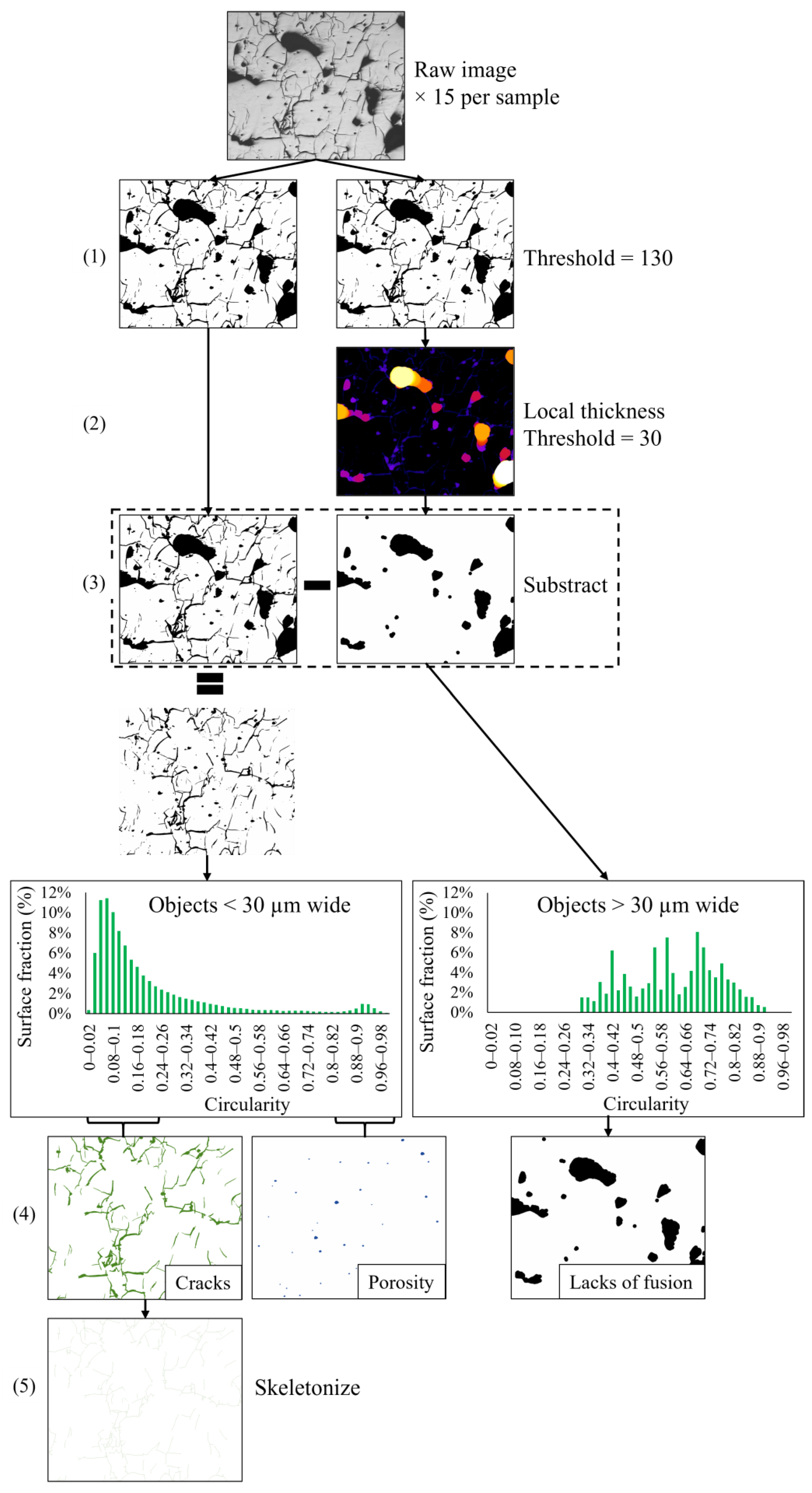
According to the representative volume’s calculation, 15 optical micrographs were used for each sample. Those micrographs were taken at a magnification of ×50, representing a surface area of 31.7 mm2 (between 17.4 and 31.7% of the surface area of each sample) with a similar grey histogram. Given the magnification (1.54 pixel·µm−1 resolution), defects larger than 6 µm can be detected. Those defects (lack of fusion, porosity, and cracks) can be connected. Therefore, they were separated and quantified using an image analysis program created with Fiji software (Version 1.54c) [60] following the steps described and summarized in Figure 3.
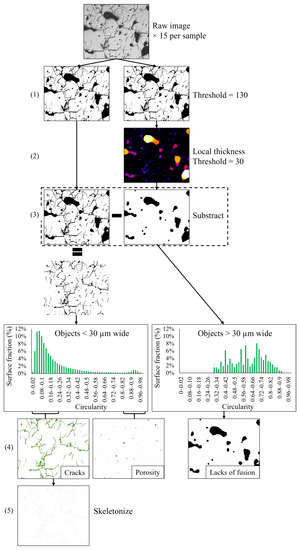
Figure 3.
Graphical summary of the program developed in Fiji to separate the different types of defects (lack of fusion, cracks, and porosity). The different steps in the program are indicated from (1) to (5).
Wide objects exhibit a circularity between 0.3 and 0.9, meaning that they were neither elongated like a crack nor were circular like a pore. Therefore, objects wider than 30 µm mainly comprised a lack of fusion. On the other side, objects finer than 30 µm exhibited two populations. The first population comprised objects with a circularity between 0 and 0.2 (elongated objects), which can be attributed to cracks. The second one comprised objects with a circularity between 0.8 and 1 (circular objects), which can be attributed to pores. The crack’s length was measured using the skeletonized image of the cracks. Crack width was determined by dividing the crack’s surface by the crack’s length. The crack angle was calculated with the angle of the major axis of the object relative to the horizontal line. Finally, the surface density was determined by subtracting the lack of fusion surface fraction to 100%.
3. Results
This section describes the results. Firstly, the processability of the alloy during these different productions is described. Secondly, material health is examined.
3.1. Processability
Processability is limited by the excessive deformation of samples during production, leading to a collision with respect to the recoater. Using standard process parameters (laser power ranging from 150 to 225 W and laser speed ranging from 455 to 1000 mm·s−1) on the standard Renishaw AM400 machine with a baseplate heated to 170 °C, most excessive deformations during production can be avoided. Indeed, only one sample (laser power = 200 W and laser speed = 588 mm·s−1) had to be stopped due to delamination (Figure 2). This set of parameters is not an extremum. Therefore, this process’s cancellation is attributed to a random error. For a baseplate preheated to 300 °C, a laser power of 150 W induces excessive deformation (Figure 2). A baseplate preheated at 500 °C allows the production of samples at low speeds (down to 200 mm·s−1) with a laser power of 100 W. However, with a very low laser scanning speed of 100 mm·s−1, excessive deformation limits the processability (Figure 2). Finally, variations in the hatch’s spacing did not appear to reduce the processability window relative to laser remelting. However, short hatch spacings combined with laser remelting could lead to excessive deformation (seen in one sample only out of the two built with low hatch spacing and laser remelting) (Figure 2).
3.2. Material Health
This section presents the three different types of defects (lack of fusion, porosity, and cracks). These are qualitatively and quantitively described.
3.2.1. Qualitative Defect Analysis
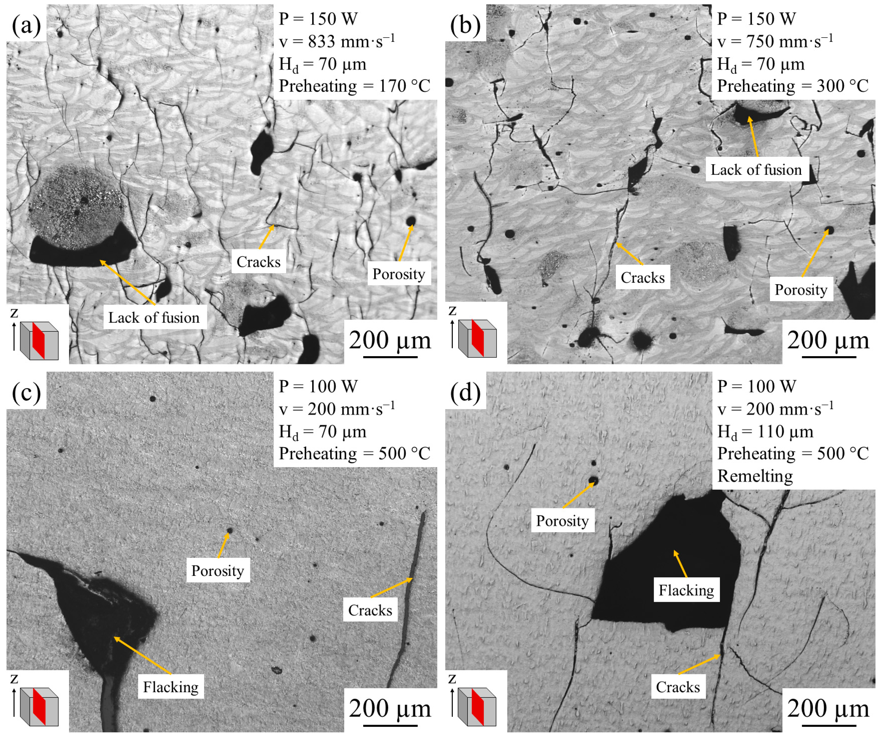
The most apparent defect found in the L-PBF production of NiCrBSi is the lack of fusion (Figure 4). Large defects with an irregular shape [16] are frequently topped by a circular object with a coarse microstructure (Figure 4a,b). However, for a baseplate preheated to 500 °C, a lack of fusion does not seem to be present (Figure 4c,d).

Figure 4.
Typical optical micrographs of four etched different samples: (a) obtained with standard preheating at 170 °C; (b) with a baseplate preheated at 300 °C; (c) at 500 °C; and (d) at 500 °C with a second laser path.
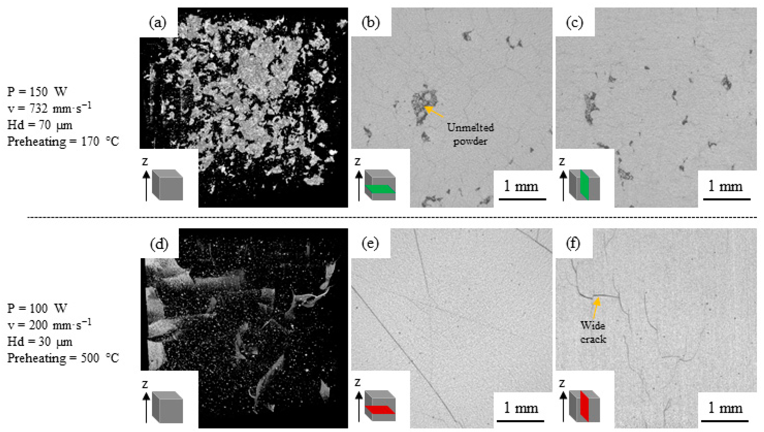
Furthermore, tomographic analysis shows unmelted and enclosed powder particles for a sample obtained with a preheating temperature of 170 °C (Figure 5a–c), confirming the presence of lack of fusion. Indeed, the presence of a lack of fusion is difficult to confirm using metallographic cross-section analysis due to the fall of powder particles during sample preparation. However, for a sample obtained with a preheating temperature of 500 °C, no such defects were found (Figure 5d–f).
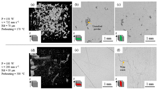
Figure 5.
Tomography analysis of two different samples: (a,d) tomography; (b,e) radiography perpendicular to the build direction; (c,f) radiography along the build direction.
The second most apparent defect in NiCrBSi L-PBF production is cracks (Figure 4). They are observed for all samples despite preheating the baseplate up to 500 °C and applying a second laser path. For a sample obtained with a baseplate preheated at 500 °C, X-ray tomography reconstruction exposed wide cracks (Figure 5d), while micrography exhibited wide cracks and flacks (Figure 4d). Therefore, these flacks are induced by sample preparation. For the sample obtained with a preheating temperature of 500 °C, cracks are concentrated on the side of the sample (Figure 5d).
Finally, some porosity can be found on the NiCrBSi produced by L-PBF (Figure 4).
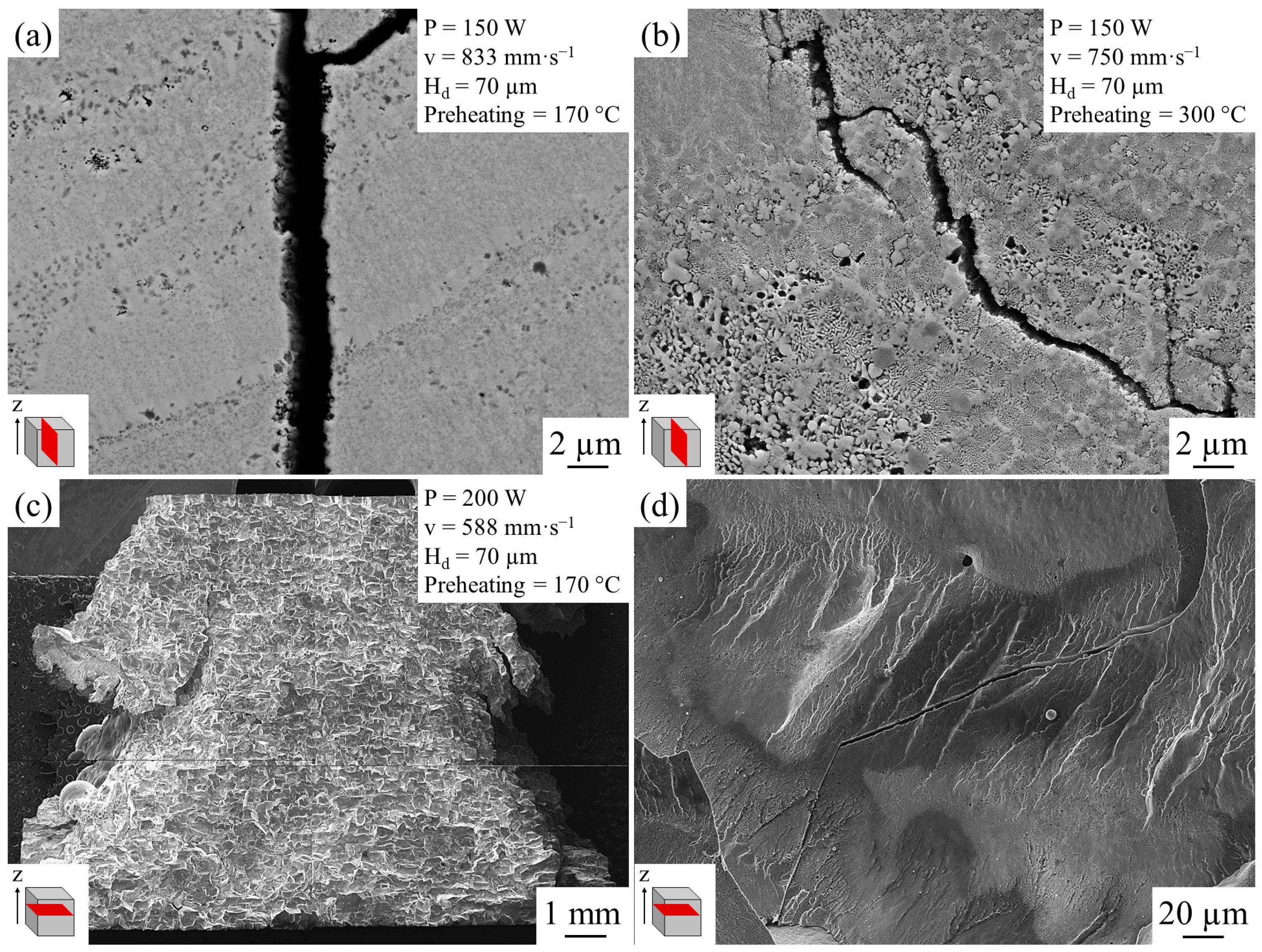
To understand crack origins, the cross sections of cracks and the fracture surface of a delaminated sample are observed. The observation of the crack’s cross section shows neither dendrites nor liquation cracking (Figure 6a,b). The fractography of a delaminated sample shows multiple facets (Figure 6c) and higher magnification shows river patterns typical of a brittle fracture (Figure 6d).
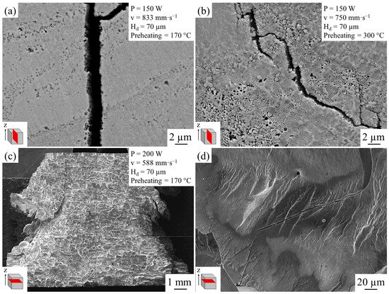
Figure 6.
Typical SEM micrographs of cracks for two different samples: (a) obtained with a standard preheating temperature at 170 °C (etched); (b) with a high preheating temperature at 300 °C (etched); (c) fractography of the delaminated sample from the standard production; (d) higher magnification fractography.
3.2.2. Quantitative Defect Analysis
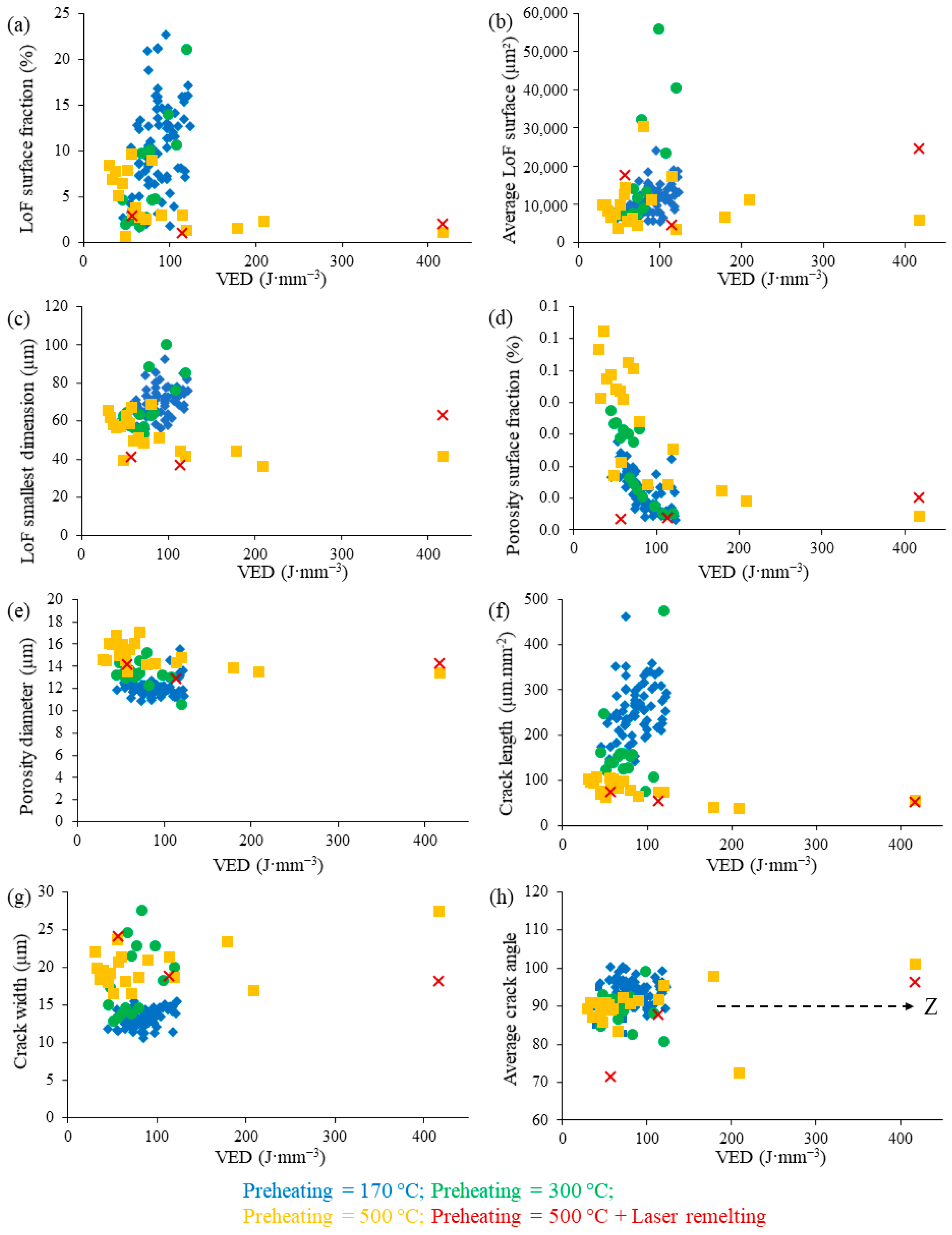
After applying the image analysis procedure explained in Figure 3 on 120 samples, defects are quantified, and results are presented in Figure 7. The lack of fusion’s surface fraction decreases globally with an increase in preheating temperature (Figure 7a). The highest lack of fusion’s surface fraction (23%) is obtained with a laser power of 150 W and a laser speed of 652 mm·s−1 and a baseplate preheated to 170 °C. The lowest lack of fusion’s surface fraction (0.7%) is obtained with a laser power of 100 W, a laser speed of 750 mm·s−1, and a preheating temperature of 500 °C. Given the low lack of fusion surface fraction already obtained with this parameter set, further laser remelting does not provide any improvement. The average surface of the lack of fusion is not well correlated with VED or preheating temperatures (Figure 7b). Finally, the smallest dimensions of the lack of fusion seem to decrease while increasing preheating temperatures (Figure 7c). It should be mentioned that this trend is not pronounced.
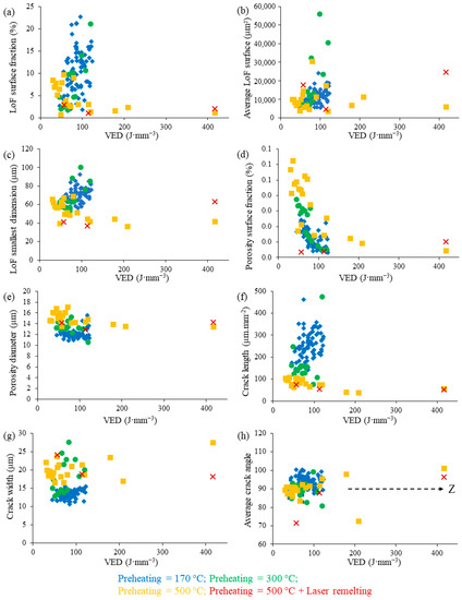
Figure 7.
Defect quantification against the VED for different preheating temperatures: (a) lack of fusion’s surface fraction; (b) lack of fusion average surface; (c) lack of fusion smallest dimension; (d) porosity surface fraction; (e) average pore diameter; (f) crack length per surface unit; (g) average crack width; (h) average crack angle.
Porosity is low for all conditions (<1%). The pores’ surface fraction decreases with a higher VED. However, it increases with preheating temperatures (Figure 7d). The lowest pore surface fraction is 0.03%, which is in line with nickel superalloys [20]. Given the low surface fraction of pores (less than 1%) compared to the lack of fusion, this aspect is not further discussed. Finally, the influence of process parameters (except preheating temperature) on the porosity diameter is not significant (Figure 7e).
The crack’s length decreases with higher preheating temperatures (Figure 7f). However, the crack’s width increases with higher preheating temperatures (Figure 7g). The large cracks are interconnected and can cause flacking after sample preparation or under load (Figure 4c and Figure 5d). Finally, the cracks are generally aligned with the building direction (Z) (Figure 7h).
4. Discussion
This part discusses the origin of different defects observed during the production and process parameters’ optimization to reduce them.
4.1. Processability
Excessive deformations during the process, leading to apparent delamination and damaging contacts with the recoater, are the main causes of poor processability. This is mostly avoided using standard process parameters, resulting in a VED of 55 to 120 J·mm−3 on a standard Renishaw AM400 machine with a 170 °C preheated baseplate (Figure 2). This is not consistent with the observations of Wang et al. [41], who describe that deformation occurs at a VED greater than 83 J·mm−3. The alloy studied by Wang et al. [41] contains a higher concentration of iron (13.1% compared to 3.1% in our study). This 10% increase in iron can lead to the apparition of new iron-rich phases. Furthermore, the lower nickel content may reduce the amount of hard nickel borides. Therefore, these chemical variations might impact the cracking tendency. For a baseplate heated to 300 °C, processing with a laser power of 150 W results in excessive deformation (Figure 2). For this preheating temperature, processability is limited to a laser power of 100 W. This can be attributed to the excessive energy received by the sample. However, preheating the baseplate up to 500 °C results in a larger process window (laser power of 100 and 150 W), which may be due to sample softening (the alloy’s solidus temperature is lower than 1000 °C [61,62,63]) or reduced thermal gradients (Figure 2). In contrast to Shishkovsky et al. [40], the production of samples with a laser power of 100 W and a laser velocity of 100 mm·s−1 is still unsuccessful despite preheating the baseplate to 500 °C. It should be mentioned that the difference in the sample’s shape (circular in the case of Shishkovsky et al. [40]) and the differences in the chemical composition between the studies of Wang et al. [41], Shishkovsky et al. [40], and this present work might lead to different behaviours. Indeed, as previously described, processability is correlated to cracking sensitivity, leading to the delamination of the sample. Therefore, the sharp angles of cubic samples (this study) can promote more cracks than the circular samples used by Shishkovsky et al. [40]. Furthermore, the higher boron content (3.5 %wt.) used in this study compared to the one used by Shishkovsky et al. [40] (2%) might generate a greater amount of brittle chromium and nickel borides, leading to a more crack-sensitive alloy.
4.2. Lack of Fusion
A surface density of 98% can be obtained using a standard Renishaw AM400 by preheating the baseplate to 170 °C (Figure 7a). This is in good agreement with the work of Wang et al. [41]. In addition, higher surface densities (up to 99%) can be archived by preheating the baseplate to 500 °C. Despite the low melting temperature of NiCrBSi alloys, the surface density is mainly affected by a large lack of fusion. It should be noted that hard chromium carbides and borides might melt at higher temperatures than the matrix [12,64,65,66]. This significant lack of fusion is topped by an area comprising a coarse microstructure (Figure 4a,b). These areas can be related to spatters ejected during production [17,67,68,69,70,71,72,73,74]. These spatters can be ejected either from the powder bed or from the melting pool [69,70]. The diameter of these spatters (around 200 µm) is greater than the layer thickness (40 µm) or the powder diameter (D90 = 47 µm). Therefore, based on several works [69,70], the spatters are ejected from the melting pool. Furthermore, the size of those spatters is in line with those found by Taheri Andani et al. [75] (from 200 to 700 µm). Therefore, based on the work of Haeckel et al. [76] and Taheri Andani et al. [75], the spatters can screen several layers of the powder bed, leading to a large lack of fusion (from several hundreds of microns to a millimetre) underneath. However, preheating the baseplate up to 500 °C and using a high VED is sufficient for melting these particles or significantly reducing their apparition (Figure 4c,d). According to Devojno et al. [77], the origin of the spatters might also be correlated to the formation of borosilicate glass due to the addition of boron and silicon as fluxing agents. Therefore, these spatters are strongly detrimental to the obtention of a defect-free part.
4.3. Cracks
According to the literature, cracks can be induced by four phenomena (solidification, liquation, ductility dip, and age cracking [18,23,24,25,26,34,35,78,79]). Due to the NiCrBSi alloys’ complexity, all these phenomena must be considered. Indeed, the high boron content of NiCrBSi alloys might generate a liquid film between dendrites, leading to solidification cracking [80]. Many eutectic components can lead to liquation cracking [24,35]. The formation of carbides at grain boundaries could lead to ductility-dip cracking [81]. The precipitation of strengthening phases during cooling might lead to age cracking [24,81]. According to the acoustic study of Wang et al. [82] on NiCrBSi alloys, these cracks can occur at any time during cooling (hot cracking and cold cracking). Therefore, NiCrBSi might be sensitive to all four types of cracking. According to Cloots et al. [36], hot cracking produces dendritic features on the cracks’ surfaces. Nevertheless, according to Platl et al. [83], a brittle cracking surface can be attributed to cold cracking. However, in this study, fracture surfaces do not contain dendrites (Figure 6a,b). Furthermore, the fractography of a delaminated sample shows a brittle fracture (Figure 6c,d). Therefore, the cracking of the NiCrBSi alloy produced by L-PBF occurs in the solid state (cold cracking). The high heating and cooling rate induced by the process could cause strong local expansions and contractions, leading to high stress levels in a material unable to accommodate significant plasticity [84]. However, preheating the baseplate to 500 °C generates more widely spaced, shorter, and wider cracks, leading to flacking (Figure 4c). Two hypotheses can be proposed to explain this behaviour. Firstly, preheating the baseplate up to 500 °C reduces thermal gradients, leading to a reduced stress gradient. Secondly, preheating the baseplate up to 500 °C might soften the sample, increasing its toughness at this temperature [85]. It should be mentioned that the crack’s dimensions might be altered by sample preparation.
4.4. Process Optimization
A compromise has to be made between the surface fraction of the lack of fusion and the width or the length of cracks. Therefore, Table 2 presents sets of parameters that produce a surface density of 98% or greater with the associated crack width and length.
Table 2.
Sets of parameters with associated surface density, crack width, and crack length per unit of area for an analyzed surface per image (2.11 mm2) out of 15 images.
As previously mentioned, preheating the baseplate to 500 °C reduces crack length. However, it increases crack width. Wide cracks can lead to catastrophic flacking or delamination. Furthermore, in the case of heat treatment, such as hot isostatic pressing (HIP), narrow cracks have a better chance of being closed than wide cracks (in the case of non-emerging cracks). Hence, the parameters set as P = 150 W, v = 732 mm·s−1, Pd = 120 µm, exp = 140 µs, Hs = 70 µm, and preheating temperature = 170 °C may provide the best compromise between low surface area and a lack of fusion (2 ± 1%) and dense but narrow cracks (11 ± 1 µm).
5. Conclusions
This paper contributes to a better understanding of the very little-studied NiCrBSi parts produced by L-PBF. Parameter sets encompassing those commonly used for other nickel-based alloys are explored. A significant lack of fusion and, as expected, cracks limit the production of NiCrBSi parts. However, our careful analysis of the relationship between material health and process parameters highlights some process parameters that are capable of producing near defect-free samples:
- Given that circular objects with a coarse microstructure are frequently observed with a lack of fusion, powder bed screening due to spatters emerging from the melting pool is the reason for the large lack of fusion;
- Preheating the baseplate up to 500 °C reduces the surface fraction of areas with a lack of fusion to less than 1%;
- Given the brittle fracture surface, cracking is most likely to occur in a solid state;
- Preheating the baseplate up to 500 °C generates widely spaced, shorter, and wider cracks due to the sample’s softening and/or thermal gradient reduction.
- The wide cracks concentrated at the sample’s corners might engender catastrophic flacking after sample preparation or under load;
- Process parameters set at a laser power of 150 W, a laser scanning speed of 732 mm·s−1, a hatch spacing of 70 µm, and a preheating temperature of 170 °C show a good compromise for obtaining a surface density of 98%, with narrow cracks that are 11 µm wide, while limiting the crack’s length per unit of area to 4 ± 0.4 mm.mm−2.
HIP could improve material health by closing small defects like cracks and porosity. Reducing the alloy’s elements could reduce its cracking tendency, making it easier to produce. The determination of ductility and toughness at high temperatures via thermomechanical tests might provide valuable information for understanding cracking behaviour.
Author Contributions
Conceptualization, A.T.; methodology, A.T.; software, A.T., M.M. and Y.B.; validation, M.M., Y.B., O.D. and J.A.; formal analysis, A.T.; investigation, A.T.; data curation, A.T.; writing—original draft preparation, A.T.; writing—review and editing, A.T., M.M., Y.B., O.D., J.R. and J.A.; supervision, M.M., Y.B., O.D., J.R. and J.A.; project administration, J.R., O.D. and J.A.; funding acquisition, J.A. All authors have read and agreed to the published version of the manuscript.
Funding
This work is part of the SPARTAN project CP/2020-DEC/09.04 financed by the Region Occitanie.
Data Availability Statement
Not applicable.
Acknowledgments
The authors acknowledge Paul Didier from the company Pint-innovative for the production of samples with their SLM Solution 250 device. We are indebted to Antoine Vezirian for his technical support regarding productions with the Renishaw AM400 device. The authors acknowledge Arnaud Votié from the company Freyssinet Aero for his help during sample separation. We would like to thank Jérome Rocchi and Jean-Marc Cloué for their expertise. Finally, the authors would like to sincerely thank Jade Pécune, Nathalie Aubazac, and Marina Fazzini for their technical support during sample preparation, SEM observations, and X-ray tomography, respectively.
Conflicts of Interest
The authors declare no conflict of interest. The funders had no role in the design of the study; in the collection, analyses, or interpretation of data; in the writing of the manuscript; or in the decision to publish the results.
References
- Tong, X.; Li, F.; Liu, M.; Dai, M.; Zhou, H. Thermal Fatigue Resistance of Non-Smooth Cast Iron Treated by Laser Cladding with Different Self-Fluxing Alloys. Opt. Laser Technol. 2010, 42, 1154–1161. [Google Scholar] [CrossRef]
- Feldshtein, E.; Kardapolava, M.; Dyachenko, O. On the Effectiveness of Multi-Component Laser Modifying of Fe-Based Self-Fluxing Coating with Hard Particulates. Surf. Coat. Technol. 2016, 307, 254–261. [Google Scholar] [CrossRef]
- Simunovic, K.; Saric, T.; Simunovic, G. Different Approaches to the Investigation and Testing of the Ni-Based Self-Fluxing Alloy Coatings—A Review. Part 1: General Facts, Wear and Corrosion Investigations. Tribol. Trans. 2014, 57, 955–979. [Google Scholar] [CrossRef]
- Serres, N.; Hlawka, F.; Costil, S.; Langlade, C.; Machi, F. Microstructures of Metallic NiCrBSi Coatings Manufactured via Hybrid Plasma Spray and In Situ Laser Remelting Process. J. Therm. Spray Technol. 2011, 20, 336–343. [Google Scholar] [CrossRef]
- Wang, D.; Liang, E.; Chao, M.; Yuan, B. Investigation on the Microstructure and Cracking Susceptibility of Laser-Clad V2O5/NiCrBSiC Alloy Coatings. Surf. Coat. Technol. 2008, 202, 1371–1378. [Google Scholar] [CrossRef]
- Sidhu, T.S.; Prakash, S.; Agrawal, R.D. Hot Corrosion Behaviour of HVOF-Sprayed NiCrBSi Coatings on Ni- and Fe-Based Superalloys in Na2SO4–60% V2O5 Environment at 900 °C. Acta Mater. 2006, 54, 773–784. [Google Scholar] [CrossRef]
- Chen, H.; Xu, C.; Qu, J.; Hutchings, I.M.; Shipway, P.H.; Liu, J. Sliding Wear Behaviour of Laser Clad Coatings Based upon a Nickel-Based Self-Fluxing Alloy Co-Deposited with Conventional and Nanostructured Tungsten Carbide–Cobalt Hardmetals. Wear 2005, 259, 801–806. [Google Scholar] [CrossRef]
- McCarron, R.; Stewart, D.; Shipway, P.; Dini, D. Sliding Wear Analysis of Cobalt Based Alloys in Nuclear Reactor Conditions. Wear 2017, 376–377, 1489–1501. [Google Scholar] [CrossRef]
- McCarron, R. An Investigation of the Wear Resistance of Bearing Materials for Nuclear Applications. Ph.D. Thesis, Imperial College London, London, UK, 2018. [Google Scholar]
- Sudha, C.; Shankar, P.; Rao, R.V.S.; Thirumurugesan, R.; Vijayalakshmi, M.; Raj, B. Microchemical and Microstructural Studies in a PTA Weld Overlay of Ni–Cr–Si–B Alloy on AISI 304L Stainless Steel. Surf. Coat. Technol. 2008, 202, 2103–2112. [Google Scholar] [CrossRef]
- Kazamer, N.; Muntean, R.; Vălean, P.C.; Pascal, D.T.; Mărginean, G.; Șerban, V.-A. Comparison of Ni-Based Self-Fluxing Remelted Coatings for Wear and Corrosion Applications. Materials 2021, 14, 3293. [Google Scholar] [CrossRef]
- Lebaili, S.; Durand-Charre, M.; Hamar-Thibault, S. The Metallurgical Structure of As-Solidified Ni-Cr-B-Si-C Hardfacing Alloys. J. Mater. Sci. 1988, 23, 3603–3611. [Google Scholar] [CrossRef]
- Liyanage, T.; Fisher, G.; Gerlich, A.P. Influence of Alloy Chemistry on Microstructure and Properties in NiCrBSi Overlay Coatings Deposited by Plasma Transferred Arc Welding (PTAW). Surf. Coat. Technol. 2010, 205, 759–765. [Google Scholar] [CrossRef]
- Hemmati, I.; Rao, J.C.; Ocelík, V.; De Hosson, J.T.M. Electron Microscopy Characterization of Ni-Cr-B-Si-C Laser Deposited Coatings. Microsc. Microanal. Off. J. Microsc. Soc. Am. Microbeam Anal. Soc. Microsc. Soc. Can. 2013, 19, 120–131. [Google Scholar] [CrossRef] [PubMed]
- Vafadar, A.; Guzzomi, F.; Rassau, A.; Hayward, K. Advances in Metal Additive Manufacturing: A Review of Common Processes, Industrial Applications, and Current Challenges. Appl. Sci. 2021, 11, 1213. [Google Scholar] [CrossRef]
- Frazier, W.E. Metal Additive Manufacturing: A Review. J. Mater. Eng. Perform. 2014, 23, 1917–1928. [Google Scholar] [CrossRef]
- Zheng, H.; Li, H.; Lang, L.; Gong, S.; Ge, Y. Effects of Scan Speed on Vapor Plume Behavior and Spatter Generation in Laser Powder Bed Fusion Additive Manufacturing. J. Manuf. Process. 2018, 36, 60–67. [Google Scholar] [CrossRef]
- Sanchez, S.; Smith, P.; Xu, Z.; Gaspard, G.; Hyde, C.J.; Wits, W.W.; Ashcroft, I.A.; Chen, H.; Clare, A.T. Powder Bed Fusion of Nickel-Based Superalloys: A Review. Int. J. Mach. Tools Manuf. 2021, 165, 103729. [Google Scholar] [CrossRef]
- Volpato, G.M.; Tetzlaff, U.; Fredel, M.C. A Comprehensive Literature Review on Laser Powder Bed Fusion of Inconel Superalloys. Addit. Manuf. 2022, 55, 102871. [Google Scholar] [CrossRef]
- Adegoke, O.; Andersson, J.; Brodin, H.; Pederson, R. Review of Laser Powder Bed Fusion of Gamma-Prime-Strengthened Nickel-Based Superalloys. Metals 2020, 10, 996. [Google Scholar] [CrossRef]
- Adegoke, O.; Andersson, J.; Brodin, H.; Pederson, R. Influence of Laser Powder Bed Fusion Process Parameters on Voids, Cracks, and Microhardness of Nickel-Based Superalloy Alloy 247LC. Materials 2020, 13, 3770. [Google Scholar] [CrossRef]
- Adegoke, O.; Polisetti, S.R.; Xu, J.; Andersson, J.; Brodin, H.; Pederson, R.; Harlin, P. Influence of Laser Powder Bed Fusion Process Parameters on the Microstructure of Solution Heat-Treated Nickel-Based Superalloy Alloy 247LC. Mater. Charact. 2022, 183, 111612. [Google Scholar] [CrossRef]
- Lee, Y.S.; Kirka, M.M.; Kim, S.; Sridharan, N.; Okello, A.; Dehoff, R.R.; Babu, S.S. Asymmetric Cracking in Mar-M247 Alloy Builds During Electron Beam Powder Bed Fusion Additive Manufacturing. Metall. Mater. Trans. Uncorrected Proof 2018, 49, 5065–5079. [Google Scholar] [CrossRef]
- Perevoshchikova, N.; Rigaud, J.; Sha, Y.; Heilmaier, M.; Finnin, B.; Labelle, E.; Wu, X. Optimisation of Selective Laser Melting Parameters for the Ni-Based Superalloy IN-738 LC Using Doehlert’s Design. Rapid Prototyp. J. 2017, 23, 881–892. [Google Scholar] [CrossRef]
- Wang, X.; Carter, L.N.; Pang, B.; Attallah, M.M.; Loretto, M.H. Microstructure and Yield Strength of SLM-Fabricated CM247LC Ni-Superalloy. Acta Mater. 2017, 128, 87–95. [Google Scholar] [CrossRef]
- Muñoz-Moreno, R.; Divya, V.D.; Driver, S.L.; Messé, O.M.D.M.; Illston, T.; Baker, S.; Carpenter, M.A.; Stone, H.J. Effect of Heat Treatment on the Microstructure, Texture and Elastic Anisotropy of the Nickel-Based Superalloy CM247LC Processed by Selective Laser Melting. Mater. Sci. Eng. A 2016, 674, 529–539. [Google Scholar] [CrossRef]
- Boswell, J.H.; Clark, D.; Li, W.; Attallah, M.M. Cracking during Thermal Post-Processing of Laser Powder Bed Fabricated CM247LC Ni-Superalloy. Mater. Des. 2019, 174, 107793. [Google Scholar] [CrossRef]
- Carter, L.N.; Wang, X.; Read, N.; Khan, R.; Aristizabal, M.; Essa, K.; Attallah, M.M. Process Optimisation of Selective Laser Melting Using Energy Density Model for Nickel Based Superalloys. Mater. Sci. Technol. 2016, 32, 657–661. [Google Scholar] [CrossRef]
- Carter, L.N. Selective Laser Melting of Nickel Superalloys for High Temperature Applications. Ph.D. Thesis, University of Birmingham, Birmingham, UK, 2013. [Google Scholar]
- Carter, L.; Attallah, M.; Reed, R. Laser Powder Bed Fabrication of Nickel-Base Superalloys: Influence of Parameters; Characterisation, Quantification and Mitigation of Cracking. In Superalloys 2012; John Wiley & Sons, Ltd.: Hoboken, NJ, USA, 2012; pp. 577–586. ISBN 978-0-470-94320-5. [Google Scholar]
- Griffiths, S.; Ghasemi Tabasi, H.; Ivas, T.; Maeder, X.; De Luca, A.; Zweiacker, K.; Wróbel, R.; Jhabvala, J.; Logé, R.E.; Leinenbach, C. Combining Alloy and Process Modification for Micro-Crack Mitigation in an Additively Manufactured Ni-Base Superalloy. Addit. Manuf. 2020, 36, 101443. [Google Scholar] [CrossRef]
- Griffiths, S.; Ghasemi-Tabasi, H.; De Luca, A.; Pado, J.; Joglekar, S.S.; Jhabvala, J.; Logé, R.E.; Leinenbach, C. Influence of Hf on the Heat Treatment Response of Additively Manufactured Ni-Base Superalloy CM247LC. Mater. Charact. 2021, 171, 110815. [Google Scholar] [CrossRef]
- Guo, C.; Li, G.; Zhou, F.; Li, X.; Xu, Z.; Liu, C.; Hu, X.; Lu, H.; Li, Z.; Zhu, Q. Understanding the Significant Effect of Boron Content on the Printability of IN738LC Superalloy Fabricated Using Laser Powder Bed Fusion. Opt. Laser Technol. 2023, 159, 108954. [Google Scholar] [CrossRef]
- Geiger, F.; Kunze, K.; Etter, T. Tailoring the Texture of IN738LC Processed by Selective Laser Melting (SLM) by Specific Scanning Strategies. Mater. Sci. Eng. A 2016, 661, 240–246. [Google Scholar] [CrossRef]
- Qiu, C.; Chen, H.; Liu, Q.; Yue, S.; Wang, H. On the Solidification Behaviour and Cracking Origin of a Nickel-Based Superalloy during Selective Laser Melting. Mater. Charact. 2019, 148, 330–344. [Google Scholar] [CrossRef]
- Cloots, M.; Uggowitzer, P.J.; Wegener, K. Investigations on the Microstructure and Crack Formation of IN738LC Samples Processed by Selective Laser Melting Using Gaussian and Doughnut Profiles. Mater. Des. 2016, 89, 770–784. [Google Scholar] [CrossRef]
- Kim, K.-S.; Yang, S.; Kim, M.-S.; Lee, K.-A. Effect of Post Heat-Treatment on the Microstructure and High-Temperature Oxidation Behavior of Precipitation Hardened IN738LC Superalloy Fabricated by Selective Laser Melting. J. Mater. Sci. Technol. 2021, 76, 95–103. [Google Scholar] [CrossRef]
- Bayoumy, D.; Kan, W.; Wu, X.; Zhu, Y.; Huang, A. The Latest Development of Sc-Strengthened Aluminium Alloys by Laser Powder Bed Fusion. J. Mater. Sci. Technol. 2023. [Google Scholar] [CrossRef]
- Zeng, C.; Ding, H.; Bhandari, U.; Guo, S.M. Design of Crack-Free Laser Additive Manufactured Inconel 939 Alloy Driven by Computational Thermodynamics Method. MRS Commun. 2022, 12, 844–849. [Google Scholar] [CrossRef]
- Shishkovsky, I.; Kakovkina, N.; Sherbakof, V. Mechanical Properties of NiCrBSi Self-Fluxing Alloy after LPBF with Additional Heating. Procedia CIRP 2020, 94, 217–221. [Google Scholar] [CrossRef]
- Wang, W.Q.; Li, Y.Q.; Li, X.; Liu, L.; Chen, F. Microstructures and Properties of Ni-Cr-B-Si Alloy Powders Prepared by Selective Laser Melting. Mater. Rep. 2020, 34, 2077–2082. [Google Scholar]
- Abe, F.; Osakada, K.; Shiomi, M.; Uematsu, K.; Matsumoto, M. The Manufacturing of Hard Tools from Metallic Powders by Selective Laser Melting. J. Mater. Process. Technol. 2001, 111, 210–213. [Google Scholar] [CrossRef]
- Shishkovsky, I.; Kakovkina, N.; Scherbakov, V. Fabrication of Heat-Resisting Nickel Composite Gradient Structures with TiC Nano Additive during Powder Bed Fusion Process. Procedia CIRP 2018, 74, 68–71. [Google Scholar] [CrossRef]
- Shishkovsky, I.; Kakovkina, N.; Sherbakov, V. Layerwise Fabrication of Refractory NiCrSiB Composite with Gradient Grow of Tungsten Carbide Additives by Selective Laser Melting. Opt. Laser Technol. 2019, 120, 105723. [Google Scholar] [CrossRef]
- Ji, W.; Liu, C.; Dai, S.; Deng, R. Microstructure, Properties and Crack Suppression Mechanism of High-Speed Steel Fabricated by Selective Laser Melting at Different Process Parameters. Chin. J. Mech. Eng. 2023, 36, 46. [Google Scholar] [CrossRef]
- Kempen, K.; Vrancken, B.; Buls, S.; Thijs, L.; Van Humbeeck, J.; Kruth, J.-P. Selective Laser Melting of Crack-Free High Density M2 High Speed Steel Parts by Baseplate Preheating. J. Manuf. Sci. Eng. 2014, 136. [Google Scholar] [CrossRef]
- Ali, H.; Ghadbeigi, H.; Mumtaz, K. Effect of Scanning Strategies on Residual Stress and Mechanical Properties of Selective Laser Melted Ti6Al4V. Mater. Sci. Eng. A 2018, 712, 175–187. [Google Scholar] [CrossRef]
- Shiomi, M.; Osakada, K.; Nakamura, K.; Yamashita, T.; Abe, F. Residual Stress within Metallic Model Made by Selective Laser Melting Process. CIRP Ann. 2004, 53, 195–198. [Google Scholar] [CrossRef]
- Liu, B.; Li, B.-Q.; Li, Z. Selective Laser Remelting of an Additive Layer Manufacturing Process on AlSi10Mg. Results Phys. 2019, 12, 982–988. [Google Scholar] [CrossRef]
- Wei, K.; Lv, M.; Zeng, X.; Xiao, Z.; Huang, G.; Liu, M.; Deng, J. Effect of Laser Remelting on Deposition Quality, Residual Stress, Microstructure, and Mechanical Property of Selective Laser Melting Processed Ti-5Al-2.5Sn Alloy. Mater. Charact. 2019, 150, 67–77. [Google Scholar] [CrossRef]
- Yasa, E.; Kruth, J.-P.; Deckers, J. Manufacturing by Combining Selective Laser Melting and Selective Laser Erosion/Laser Re-Melting. CIRP Ann. 2011, 60, 263–266. [Google Scholar] [CrossRef]
- ISO 4497:2020; Poudres Métalliques—Détermination de la Granulométrie Par Tamisage à Sec. International Organization for Standardization: Geneva, Switzerland, 2020.
- Ghoussoub, J.N.; Tang, Y.T.; Panwisawas, C.; Németh, A.; Reed, R.C. On the Influence of Alloy Chemistry and Processing Conditions on Additive Manufacturability of Ni-Based Superalloys. In Proceedings of the Superalloys 2020; Tin, S., Hardy, M., Clews, J., Cormier, J., Feng, Q., Marcin, J., O’Brien, C., Suzuki, A., Eds.; Springer International Publishing: Cham, Switzerland, 2020; pp. 153–162. [Google Scholar]
- Demir, A.G.; Colombo, P.; Previtali, B. From Pulsed to Continuous Wave Emission in SLM with Contemporary Fiber Laser Sources: Effect of Temporal and Spatial Pulse Overlap in Part Quality. Int. J. Adv. Manuf. Technol. 2017, 91, 2701–2714. [Google Scholar] [CrossRef]
- Harrison, N.; Todd, I.; Mumtaz, K. Reduction of Micro-Cracking in Nickel Superalloys Processed by Selective Laser Melting: A Fundamental Alloy Design Approach. Acta Mater. 2015, 94. [Google Scholar] [CrossRef]
- Karabulut, Y.; Tascioglu, E.; Kaynak, Y. Heat Treatment Temperature-Induced Microstructure, Microhardness and Wear Resistance of Inconel 718 Produced by Selective Laser Melting Additive Manufacturing. Optik 2021, 227, 163907. [Google Scholar] [CrossRef]
- Xu, Z.; Hyde, C.J.; Tuck, C.; Clare, A.T. Creep Behaviour of Inconel 718 Processed by Laser Powder Bed Fusion. J. Mater. Process. Technol. 2018, 256, 13–24. [Google Scholar] [CrossRef]
- Salarian, M.; Asgari, H.; Vlasea, M. Pore Space Characteristics and Corresponding Effect on Tensile Properties of Inconel 625 Fabricated via Laser Powder Bed Fusion. Mater. Sci. Eng. A 2020, 769, 138525. [Google Scholar] [CrossRef]
- Ali, U.; Fayazfar, H.; Ahmed, F.; Toyserkani, E. Internal Surface Roughness Enhancement of Parts Made by Laser Powder-Bed Fusion Additive Manufacturing. Vacuum 2020, 177, 109314. [Google Scholar] [CrossRef]
- Schindelin, J.; Arganda-Carreras, I.; Frise, E.; Kaynig, V.; Longair, M.; Pietzsch, T.; Preibisch, S.; Rueden, C.; Saalfeld, S.; Schmid, B.; et al. Fiji: An Open-Source Platform for Biological-Image Analysis. Nat. Methods 2012, 9, 676–682. [Google Scholar] [CrossRef]
- Gómez-del Río, T.; Garrido, M.A.; Fernández, J.E.; Cadenas, M.; Rodríguez, J. Influence of the Deposition Techniques on the Mechanical Properties and Microstructure of NiCrBSi Coatings. J. Mater. Process. Technol. 2008, 204, 304–312. [Google Scholar] [CrossRef]
- Niranatlumpong, P.; Koiprasert, H. Phase Transformation of NiCrBSi–WC and NiBSi–WC Arc Sprayed Coatings. Surf. Coat. Technol. 2011, 206, 440–445. [Google Scholar] [CrossRef]
- Arias-González, F.; del Val, J.; Comesaña, R.; Penide, J.; Lusquiños, F.; Quintero, F.; Riveiro, A.; Boutinguiza, M.; Pou, J. Fiber Laser Cladding of Nickel-Based Alloy on Cast Iron. Appl. Surf. Sci. 2016, 374, 197–205. [Google Scholar] [CrossRef]
- Hemmati, I.; Huizenga, R.M.; Ocelík, V.; De Hosson, J.T.M. Microstructural Design of Hardfacing Ni–Cr–B–Si–C Alloys. Acta Mater. 2013, 61, 6061–6070. [Google Scholar] [CrossRef]
- Lebaili, S.; Hamar-Thibault, S. Equilibres liquide-solide dans le systeme Ni-B-Si dans la region riche en nickel. Acta Metall. 1987, 35, 701–710. [Google Scholar] [CrossRef]
- Hemmati, I.; Ocelik, V.; Csach, K.; de Hosson, J.T.M. Microstructure and Phase Formation in a Rapidly Solidified Laser-Deposited Ni-Cr-B-Si-C Hardfacing Alloy. Metall. Mater. Trans.-Phys. Metall. Mater. Sci. 2014, 45A, 878–892. [Google Scholar] [CrossRef]
- Khairallah, S.A.; Anderson, A.T.; Rubenchik, A.; King, W.E. Laser Powder-Bed Fusion Additive Manufacturing: Physics of Complex Melt Flow and Formation Mechanisms of Pores, Spatter, and Denudation Zones. Acta Mater. 2016, 108, 36–45. [Google Scholar] [CrossRef]
- Cooke, S.; Ahmadi, K.; Willerth, S.; Herring, R. Metal Additive Manufacturing: Technology, Metallurgy and Modelling. J. Manuf. Process. 2020, 57, 978–1003. [Google Scholar] [CrossRef]
- Gasper, A.N.D.; Szost, B.; Wang, X.; Johns, D.; Sharma, S.; Clare, A.T.; Ashcroft, I.A. Spatter and Oxide Formation in Laser Powder Bed Fusion of Inconel 718. Addit. Manuf. 2018, 24, 446–456. [Google Scholar] [CrossRef]
- Santecchia, E.; Spigarelli, S.; Cabibbo, M. Material Reuse in Laser Powder Bed Fusion: Side Effects of the Laser—Metal Powder Interaction. Metals 2020, 10, 341. [Google Scholar] [CrossRef]
- Wang, D.; Wu, S.; Fu, F.; Mai, S.; Yang, Y.; Liu, Y.; Song, C. Mechanisms and Characteristics of Spatter Generation in SLM Processing and Its Effect on the Properties. Mater. Des. 2017, 117, 121–130. [Google Scholar] [CrossRef]
- Liu, Y.; Yang, Y.; Mai, S.; Wang, D.; Song, C. Investigation into Spatter Behavior during Selective Laser Melting of AISI 316L Stainless Steel Powder. Mater. Des. 2015, 87, 797–806. [Google Scholar] [CrossRef]
- Yin, J.; Yang, L.; Yang, X.; Zhu, H.; Wang, D.; Ke, L.; Wang, Z.; Wang, G.; Zeng, X. High-Power Laser-Matter Interaction during Laser Powder Bed Fusion. Addit. Manuf. 2019, 29, 100778. [Google Scholar] [CrossRef]
- Nudelis, N.; Mayr, P. A Novel Classification Method for Pores in Laser Powder Bed Fusion. Metals 2021, 11, 1912. [Google Scholar] [CrossRef]
- Taheri Andani, M.; Dehghani, R.; Karamooz-Ravari, M.R.; Mirzaeifar, R.; Ni, J. Spatter Formation in Selective Laser Melting Process Using Multi-Laser Technology. Mater. Des. 2017, 131, 460–469. [Google Scholar] [CrossRef]
- Haeckel, F.; Meixlsperger, M.; Burkert, T. Technological Challenges for Automotive Series Production in Laser Beam Melting; University of Texas at Austin: Austin, TX, USA, 2017. [Google Scholar]
- Devojno, O.G.; Feldshtein, E.; Kardapolava, M.A.; Lutsko, N.I. On the Formation Features, Microstructure and Microhardness of Single Laser Tracks Formed by Laser Cladding of a NiCrBSi Self-Fluxing Alloy. Opt. Lasers Eng. 2018, 106, 32–38. [Google Scholar] [CrossRef]
- Chauvet, E.; Kontis, P.; Jägle, E.A.; Gault, B.; Raabe, D.; Tassin, C.; Blandin, J.-J.; Dendievel, R.; Vayre, B.; Abed, S.; et al. Hot Cracking Mechanism Affecting a Non-Weldable Ni-Based Superalloy Produced by Selective Electron Beam Melting. Acta Mater. 2018, 142, 82–94. [Google Scholar] [CrossRef]
- Yang, J.; Li, F.; Wang, Z.; Zeng, X. Cracking Behavior and Control of Rene 104 Superalloy Produced by Direct Laser Fabrication. J. Mater. Process. Technol. 2015, 225, 229–239. [Google Scholar] [CrossRef]
- Liu, L.; Wang, W.; Zhang, X.; Li, X.; Tian, Y.; Zhao, X. Microstructures and Mechanical Properties of Nb Nanoparticles Modified Ni60 Hard-Facing Alloy Fabricated by Laser Metal Deposition. Mater. Sci. Eng. A 2021, 814, 141238. [Google Scholar] [CrossRef]
- Attallah, M.M.; Jennings, R.; Wang, X.; Carter, L.N. Additive Manufacturing of Ni-Based Superalloys: The Outstanding Issues. MRS Bull. 2016, 41, 758–764. [Google Scholar] [CrossRef]
- Wang, F.; Mao, H.; Zhang, D.; Zhao, X.; Shen, Y. Online Study of Cracks during Laser Cladding Process Based on Acoustic Emission Technique and Finite Element Analysis. Appl. Surf. Sci. 2008, 255, 3267–3275. [Google Scholar] [CrossRef]
- Platl, J.; Bodner, S.; Hofer, C.; Landefeld, A.; Leitner, H.; Turk, C.; Nielsen, M.-A.; Demir, A.G.; Previtali, B.; Keckes, J.; et al. Cracking Mechanism in a Laser Powder Bed Fused Cold-Work Tool Steel: The Role of Residual Stresses, Microstructure and Local Elemental Concentrations. Acta Mater. 2022, 225, 117570. [Google Scholar] [CrossRef]
- Zhang, Q.; Wang, Z.; Hu, F.; Song, Z. Preparation of Thin NiCrBSi Laser Cladding Layers with No Microcracking and Low Dilution. J. Laser Appl. 2019, 31, 032015. [Google Scholar] [CrossRef]
- Corchia, M.; Delogu, P.; Nenci, F.; Belmondo, A.; Corcoruto, S.; Stabielli, W. Microstructural Aspects of Wear-Resistant Stellite and Colmonoy Coatings by Laser Processing. Wear 1987, 119, 137–152. [Google Scholar] [CrossRef]
Disclaimer/Publisher’s Note: The statements, opinions and data contained in all publications are solely those of the individual author(s) and contributor(s) and not of MDPI and/or the editor(s). MDPI and/or the editor(s) disclaim responsibility for any injury to people or property resulting from any ideas, methods, instructions or products referred to in the content. |
© 2023 by the authors. Licensee MDPI, Basel, Switzerland. This article is an open access article distributed under the terms and conditions of the Creative Commons Attribution (CC BY) license (https://creativecommons.org/licenses/by/4.0/).