Abstract
Previous studies have indicated that the preformed martensite has a significant effect on the subsequent bainite transformation of nanobainite bearing steel, but its effects on the microstructure and mechanical properties are still unclear. In this paper, the effects of preformed martensite and its volume fraction on microstructure and mechanical properties of nanobainite bearing steel were investigated by using scanning electron microscope, transmission electron microscope, X-ray diffractometer and wear resistance experiments. It was demonstrated that the introduction of preformed martensite can refine bainitic microstructure and increase the volume fraction of retained austenite, but reduces the mechanical stability of retained austenite. When the volume fraction of preformed martensite is less than 20%, the hardness and wear resistance of nanobainite bearing steel gradually increases with the increase in the volume fraction of preformed martensite, but the toughness of steel decreases gradually. When the volume fraction of preformed martensite reaches 25%, the properties of nanobainite bearing steel, especially the wear resistance, obviously deteriorate. The optimized volume fraction of preformed martensite is ~10%–15% by comprehensive comparison the mechanical properties of nanobainite bearing steel.
1. Introduction
It is well known that refining the grain of material can improve its the strength and toughness simultaneously. When the size of grains is reduced to nanometers, materials will show excellent properties [1,2]. Bhadeshia et al. developed a nanobainite structure with excellent properties in a high carbon and high silicon steel by using a simple heat treatment process [3]. Since then, the nanobainite steel has attracted wide attention [4,5,6]. However, the low isothermal temperature of nanobainite and high content of alloy elements in steel, such as C and Si [7], result in a long transformation time of nanobainite steel, which restricts the possible applications of the steel. Therefore, accelerating the phase transformation of nanobainite has become the focus of researchers [8,9].
Introducing preformed martensite before bainite transformation has been demonstrated to be effective to accelerate the bainite phase transformation process, which has received a lot of attention and research in recent years [10,11,12,13,14]. Furuhara et al. found that the preformed martensite could change the orientation of the surrounded bainitic ferrite to be consistent with the orientation of martensite, indicating that the stress induced by martensite transformation facilitated the variant selection of bainitic ferrite [15]. Some studies suggested that compared with the traditional process, the preformed martensite process could refine bainitic ferrite and improve the impact toughness and fracture ductility of the steel [16,17,18]. Avishan et al. revealed that the introduction of martensite improved the yield strength and tensile strength of the tested steel [19]. Lu et al. found that multi-stage phase transformation produced a large number of small-angle grain boundaries in bainite/martensite dual-phase steel, which simultaneously improved the strength and toughness of the material. The preformed martensitic process formed film and carbon-rich retained austenite (RA), which improved the mechanical stability of RA [20]. Wang et al. found that the volume fraction of small-sized blocky RA along martensite boundaries and filmy RA between martensite plates were increased gradually with increasing volume fraction of preformed martensite [21]. It can be found that the microstructure and mechanical properties of the steel after introducing preformed martensite were notably changed, which is crucial for the application of the steel. Therefore, it is vital to focus on the evolution of microstructure and properties of bainite steel after the accelerated phase transformation process.
Previously, our group found that introducing preformed martensite in high-carbon nanobainitic bearing steel can significantly accelerated the bainite transformation at an early stage, but has no significant effect on the overall transformation time [22]. The influence of preformed martensite on the microstructure and properties of a high-carbon nanobainitic bearing steel has not been studied clearly, and the volume fraction of preformed martensite has not been optimized.
In this paper, a high-carbon nanostructured bainitic bearing steel was used as the test material, and a series amount of preformed martensite from 0% to 25% were introduced through adjusting the first-order isothermal temperature. The microstructure and mechanical properties of these specimens were characterized in detail, with an aim of revealing the effect of preformed martensite on nanostructured bainitic bearing steel and providing a theory guidance on the processing process of the bearing steel.
2. Experimental Materials and Methods
The experimental steel is referred to as GCr15Si1Mo in this paper, and its chemical composition was Fe–0.97C–0.37Mn–1.24Si–1.58Cr–0.34Mo (wt.%), determined by spectroscopic analysis. The experimental steel was melted in a vacuum induction furnace, and the steel was then pretreated by forging and spheroidizing annealing. Cylindrical specimens with lengths of 10 mm and diameters of 4 mm for dynamic quenching experiments were prepared by electric spark cutting. The Ms point was measured using a DIL805A/D dilatometer (TA Instruments, New Castle, DE, USA), and the process was as follows: the specimens were heated to 860 °C at a rate of 10 °C/s and held at that point for 30 min, then cooled to room temperature at a rate of 30 °C/s. The Ms point was determined to be 201 °C. Two types of heat treatment process were designed according to the Ms point, as shown in Figure 1. (1) The "no preformed martensite process”, that is the specimens were austenitized at 860 °C for 30 min, and then directly austempered at 210 °C for 24 h to obtain bainite. (2) “Preformed martensite process”, via a two steps isothermal treatment. The volume fraction of preformed martensite can be estimated by using the K–M equation [23]: VM = , where VM is the volume fraction of martensite and TQ is the first-step isothermal temperature. When the specimens were quenched to 4 °C, 9 °C, 14 °C, 19 °C and 24 °C below Ms temperature, respectively, volume fractions of preformed martensite of 5%, 10%, 15%, 20% and 25%, can be obtained, respectively. Accordingly, the austenitized specimens were quenched to 197 °C, 192 °C, 187 °C, 182 °C and 177 °C, and held for 1 min; then the temperature increased to 210 °C for 24 h. The processed specimens were named according to the volume fraction of preformed martensite as 0 M, 5 M, 10 M, 15 M, 20 M and 25 M.
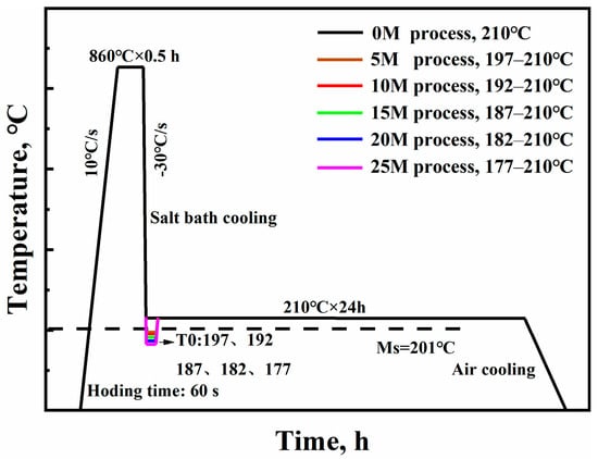
Figure 1.
Heat treatment process of test steel.
The phase constitution of the steel was characterized via X-ray diffraction (XRD) with Co Kα radiation. Specimens were step scanned from 40° to 130° with a scan rate of 1 °/min. The volume fraction of retained austenite (VRA) was calculated by Equation (1) [24,25].
where n is the number of peaks examined, I is the integrated intensity of the diffraction peak, R is a material scattering factor, υ is the volume of unit cell, F is the structure factor, P is the multiplicity factor, e−2M is the temperature factor and θ is the diffraction angle. The volume fraction of bainitic ferrite (VBF) was calculated by the Equation (3).
VBF = (1 − VM − VRA − VCem)
The microstructural observations were conducted through scanning electron microscope (SEM, SU5000 HITACHI, Tokyo, JPN) and transmission electron microscope (TEM, Talos F200X FEI, Hillsboro, OR, USA). The SEM specimens were etched using a 4% Nital solution. The TEM specimens were grinded to 30 μm, and then thinned to perforation on a TenuPol-5 twin-jet (Struers, Ballerup, Denmark) unit at a voltage of 27 V with an electrolyte consisting of 7% chloric acid and 93% ethanol.
The impact toughness of the specimens was obtained by using unnotched Charpy impact specimens with dimensions of 10 mm × 10 mm × 55 mm. Three specimens were tested for each process. The hardness of the specimens was tested with a HR-150A Rockwell hardness tester. The hardness values were obtained after seven tests for each specimen. Wear resistance in dry sliding friction of specimens was tested on an MMU-5G wear testing machine at room temperature. The load was 1000 N and the rotation rate was 200 r/min. The wear test was discontinuous; at the beginning of test, the specimens were pre-weared for 5 min, and the cumulative wear time was 2 h. Weight loss was measured every 20 min after ultrasonic cleaning. The geometry of the specimens tested in the tribometer were discs of 3 mm × φ43 mm. The quenched and low temperature tempered GCr15 steel (Fe–0.96C–0.36Mn–0.22Si–1.48Cr–0.02Al (wt.%) was used as the friction pairs. The hardness of friction pairs was 64.8 HRC. The surface morphologies of wear specimens were characterized by a Contour GT-K 3D optical interferometer (Bruker, Karlsruhe, Germany).
3. Results and Discussion
3.1. Effect of Volume Fraction of Preformed Martensite on Microstructure of Nanobainitic Bearing Steel
Figure 2 shows the SEM images of specimens with different heat treatment processes. The microstructure of specimens consists of nanobainitic ferrite, spherical cementite (Cem) and grey blocky retained austenite. The statistic results show that the volume fraction of cementite is 6%. The dark lenticular preformed martensite (Pre-M) and more grey blocky retained austenite can be observed in the microstructures of the Pre-M process specimens (Figure 2e,f). Compared with the specimens containing Pre-M, the amount of blocky RA in the microstructure of 0M specimen is lower, as shown in Figure 2a.
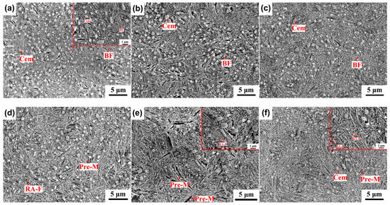
Figure 2.
SEM images of specimens with different treatment processes: (a) 0 M, (b) 5 M, (c) 10 M, (d) 15 M, (e) 20 M, (f) 25 M. BF: bainitic ferrite, Cem: cementite, Pre-M: preformed martensite, RA-F: filmy retained austenite, RA-B: blocky retained austenite.
The TEM images in Figure 3 show the typical morphologies of nanobainitic ferrite, cementite and blocky /filmy RA. Bainitic ferrite nucleates and grows at the interface of RA and Pre-M, which is likely be divided by Pre-M, as shown in Figure 3f. Moreover, the thickness of Pre-M plates is larger than that of bainitic ferrite. The thicknesses of bainitic ferrite plates (tB) are obtained from TEM images according to Equation (4) [25,26].
where L is the mean linear intercept. The result is shown in Figure 4. It can be seen that introducing preformed martensite notably refined the plate of bainitic ferrite. With an increase of the volume fraction of Pre-M from 0 to 20%, the plate thickness of bainitic ferrite decreases gradually from 73.3 nm to 56.6 nm. By further increasing PM to 25%, the plate thickness seems to have reached saturation level, and no further reduction can be observed.
tB = 2L/π
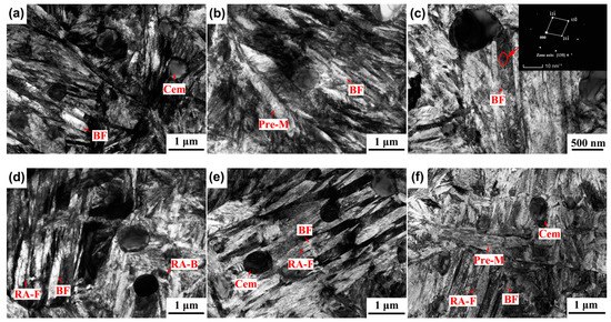
Figure 3.
TEM images of specimens with different treatment processes: (a) 0 M, (b) 5 M, (c) 10 M, (d) 15 M, (e) 20 M, (f) 25 M.
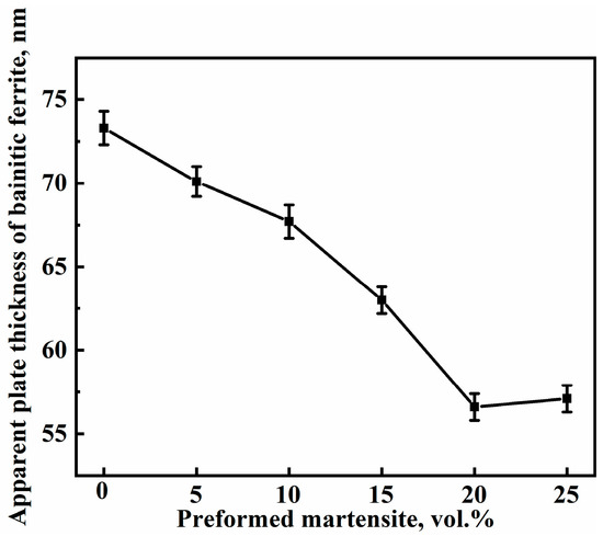
Figure 4.
Apparent plate thickness of bainitic ferrite of specimens with different treatment processes. Note: For each specimen, about 400 measurements were conducted on multiple TEM images to obtain statistically representative results.
Previous studies have demonstrated that Pre-M provides more nucleation sites for bainitic ferrite, which results in the refinement of bainitic ferrite [27]. On the other hand, the strength of the untransformed supercooled austenite is a key factor affecting the thickness of the bainitic ferrite plates [28,29]. Compared with the 0M specimen, the dislocation density of the untransformed supercooled austenite of the Pre-M specimens is higher due to martensite transformation. Meanwhile, the supersaturated carbon atoms in the martensite partially diffuse into RA during the bainite transformation. This leads to an increase in the strength of the untransformed supercooled austenite. Therefore, preforming martensite refines the thickness of bainitic ferrite plates of steel.
Figure 5a shows the XRD patterns of specimens with different processes, which indicates that specimens are mainly composed of two phases of austenite (FCC) and ferrite (BCC). Moreover, a diffraction peak of cementite phase near 37° can be observed. The percentage of the phase was calculated from the size of the peak, according to Equations (1) and (2). Figure 5b shows partial patterns of the (200)γ peak. The 2θ angle (the peak position) of the (200)γ peak of the 0M specimen is smaller than that of the specimens with preformed martensite, which indicates that the mean carbon content in retained austenite of 0 M specimen is higher than those of the preformed martensite specimens [30]. The carbon content of retained austenite decreases with the increase in the volume fraction of preformed martensite, which reveals a lower stability of retained austenite in Pre-M specimen. The high dislocations in the preformed martensite can trap more C atoms and then reduce the carbon content that eventually diffuses into the untransformed austenite, which should be responsible for the reduced carbon content in RA of Pre-M specimen.
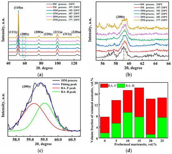
Figure 5.
(a) XRD patterns, (b) partial patterns of (200) γ peak, (c) Gaussian fitting curves of (200) γ peak of 10 M specimen, (d) volume fractions of blocky and filmy retained austenite.
Figure 5d shows that the volume fraction of retained austenite first increases and then decreases with the increase in the volume fraction of preformed martensite, which reaching a peak value of 19.6% for the 15 M specimen. Furthermore, the (200) γ peak was selected as the fitting processing peak to estimate the volume fractions of two kinds of retained austenite by using the Gaussian multi-peaks fitting method [31]. Figure 5d shows that, with increasing the volume fraction of PM, the volume fraction of filmy RA first increases, and then later decreases. When the volume fraction of preformed martensite is 20%, the volume fraction of filmy retained austenite reaches the maximum value of 12.8%.
The martensite preformed before the bainite transformation continuously divides the parent austenite grains, resulting in a decrease in the effective grain size. At the same time, the preformed martensite significantly lends to the dislocation density within the austenite increases. These two factors contribute to an increased stabilization of austenite. Therefore, the volume fraction of retained austenite of the specimens with preformed martensite are higher than that of the 0 M specimen, and more blocky retained austenite remains at room temperature.
Table 1 shows the volume fraction of each phase of specimens with different treatment processes; the volume fraction of bainitic ferrite was calculated according to the volume fraction of retained austenite and martensite. The dislocation density was estimated by using the Williamson–Hall (W–H) plot method [32]. From the results, although the change of dislocation density in ferrite phase (including bainitic ferrite and martensite) of all specimens are small, the dislocation density increases and then decreases slightly with the increase in the volume fraction of preformed martensite.

Table 1.
The volume fraction of each phase and the dislocation density in ferrite phase (ρf) of specimens with different treatment processes.
3.2. Effect of Volume Fraction of Preformed Martensite on Mechanical Properties of Nanobainite Bearing Steel
3.2.1. Hardness and Toughness
Figure 6 shows the variations of hardness and toughness of specimens with the volume fraction of PM. The hardness of all specimens is higher than 58 HRC, which meet the hardness requirements of bearing steel. The hardness of Pre-M specimens are slightly higher than that of 0M specimens. With the increase in volume fraction of preformed martensite, the hardness of the specimen first increases, and then slightly decreases. The hardness of 15 M specimen is highest (62.3 HRC)—2.1 HRC higher than that of the 0 M specimen. The impact toughness of the specimens decreases gradually from 120 J/cm2 to 30 J/cm2, with the increase in the volume fraction of PM from 0% to 25%.
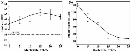
Figure 6.
Mechanical properties of specimens with different treatment processes: (a) Hardness, (b) Toughness.
The introduced martensite is a hard phase which can effectively improve the hardness of specimens. The increased dislocation density showed in Table 1 and the refined bainitic ferrite plates also play important roles in strengthening the specimens [10]. However, the preformed martensite underwent self-tempering during the bainite transformation. The amount of supersaturated carbon atoms in the martensite plate decreases, which weakens the solid solution strengthening effect of carbon atoms [33]. Moreover, the introduction of martensite lends to an increase in the volume fraction of retained austenite of the specimens, which also reduces the hardness of the specimen. Therefore, the combined effect of the two factors results in a small increase in the hardness of the specimens with preformed martensite.
The morphology of the retained austenite of 0 M specimen is mostly filmy, as shown in Figure 2 and Figure 3, which is thus considered to be main reason for the delay crack propagation [34]. Therefore, the 0 M specimen exhibits the highest impact toughness. With the increase in volume fraction of preformed martensite, the volume fraction of blocky retained austenite in specimens increases, and the carbon content of retained austenite decreases. These two factors directly contribute to the decreased toughness of nanobainite steel [30,35]. Moreover, the preformed martensite divides the parent austenite grains and generates a large stress concentration, especially at the grain boundary, which leads to a decrease in the energy of crack nucleation. When the specimen is subjected to impact loading, the stress concentration increases the probability of crack initiation [36]. In summary, these results indicate that the introduction of martensite in nanobainite bearing steel has a negative effect on the toughness of the specimens.
3.2.2. Wear Resistance
Figure 7 shows the relationship between weight loss and wear time of specimens with different processes. It can be seen that the wear resistance of specimen with the preformed martensite is higher than that of 0 M specimen, with the exception of the 25 M specimen. As the volume fraction of preformed martensite increases from 0% to 10%, the wear resistance of specimen improves as demonstrated by the gradually decreased weight loss. When the volume fraction of preformed martensite increases from 10% to 20%, although the hardness of the specimens increases slightly, the wear resistance of the specimens does not increase significantly. As the volume fraction of preformed martensite increases from 20% to 25%, the weight loss of specimen increases notably, indicating deteriorated wear resistance. Specifically, the weight loss of 10 M and 15 M specimens are almost the same, and the weight loss of the 20 M specimen is the smallest.
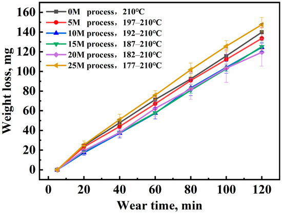
Figure 7.
Relationship between weight loss and wearing time of specimens with different treatment processes.
Figure 8 shows the worn surface of the specimens after 120 min of wear, which was characterized by Contour GT-K 3D optical interferometer (Bruker, Karlsruhe, Germany). The red and blue parts in the images represent the reference surface and wear traces, respectively. The deep wear furrows on the test specimen can be observed under applied wear loads for 120 min. Table 2 shows the roughness of the worn surface and the depth in the furrow section of different specimens. With the increase in volume fraction of preformed martensite, the average roughness of worn surfaces and the maximum wear depth of the steel first increase and then decrease. Moreover, the specimen with low roughness of wear surface also has shallow wear depth. The regulation is consistent with the cumulative weight loss presented in Figure 7. According to the spalling volume, the wear resistance of the 20 M specimen is 59.3% higher than that of the 0 M specimen.
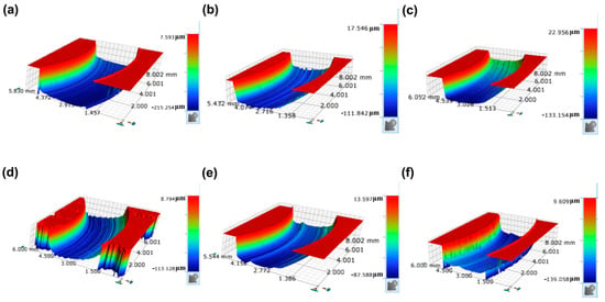
Figure 8.
3D optical interferometry images of the surface topography: (a) 0 M, (b) 5 M, (c) 10 M, (d) 15 M, (e) 20 M, (f) 25 M.The numbers in the Figure 8 represent the size of the observed part of specimens with different treatment processes.

Table 2.
The roughness of the worn surface and the depth in the furrow section of different specimens.
Figure 9 shows the worn surface morphologies of the specimens. A large number of furrows spalling pits and micro-cutting slides can be observed on the worn surface, as shown in Figure 9a,b, and many white oxide particles also distribute on the worn surface. It can be deduced that the wear mechanism of 0 M and 5 M specimens is oxidative wear and abrasive wear. In addition to spalling pits and micro-cutting slides, squamous lamellar structures are found in Figure 9c,d. This is because contact surfaces between the specimen and friction pair adhere to each other under the action of friction heat during the wear process. Subsequently, the worn surfaces are torn under shear stress. Finally, the worn surface exhibits rough adhesive wear morphology [37]. Consequently, the wear mechanism of 10 M and 15 M specimens are mainly adhesive wear, abrasive wear and mild oxidation wear. The slides on the worn surface of 20M specimen are fewest and shallowest. A few wear scratches can also be observed on the worn surface of 20 M specimen showed in Figure 9e. The worn surface of 20 M specimen is relatively flat, with no trace of adhesive wear on the worn surface. This is consistent with the results of the lowest worn surface roughness. Wear debris and shed cementite particles are generate during the wear process; these particles roll along with the movement of the friction pair, thus forming scratches on worn surface of specimen. The obvious spalling pits and oxide layers can be observed in Figure 9f, indicating that the wear mechanism of 25 M specimen is oxidative wear and abrasive wear.
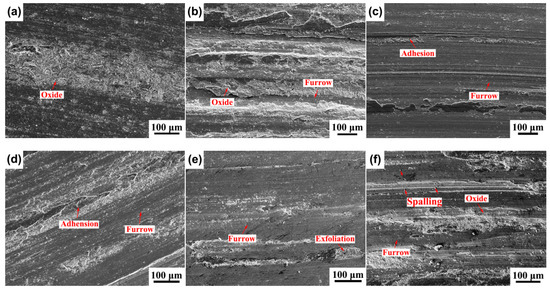
Figure 9.
Worn surface morphology of different processes: (a) 0 M, (b) 5 M, (c) 10 M, (d) 15 M, (e) 20 M, (f) 25 M.
The improvement effect of introducing preformed martensite on wear resistance can be clearly demonstrated based on the above wear results and surface morphologies. The introduction of preformed martensite improves the hardness of specimens, which directly contributes to the improved wear resistance [38]. However, for the 25M specimen, it can be seen that the volume fraction of preformed martensite is not proportional to the wear resistance. Rementeria et al. found that the wear resistance was determined by the hardness and toughness of the material [39]. Microcracks nucleate at the subsurface layer of the steel during the wear process, and the initiation and propagation of cracks are directly related to the toughness of steel. The toughness of the specimens decreases with the introduction of preformed martensite, which easily induces the nucleation and propagation of cracks [40]. Therefore, the notably decreased toughness should be responsible for the deteriorate wear resistance of 25 M specimens.
It also can be seen that the variation of weight loss of specimens is consistent with in that of volume fraction of retained austenite (Table 1 and Figure 7). This indicates that the retained austenite has a great influence on the wear resistance of specimen. The surface of the specimen undergoes plastic deformation during the wear process. The retained austenite is prone to martensitic transformation under stress. On the one hand, martensitic transformation improves the hardness of the specimen and the wear resistance of specimen [41]. On the other hand, the transformation of retained austenite into martensite causes volume expansion and introduces the compressive stress, which can retard crack propagation, and thus improves wear resistance [40]. The XRD patterns of worn surface of specimens with different processes (Figure 10) show that no austenite peaks can be observed, which proves that the retained austenite has been completely transformed into martensite. Therefore, the increase in the volume fraction of retained austenite contributes to the improvement of the wear resistance of Pre-M specimens.
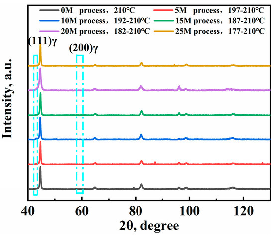
Figure 10.
XRD patterns on worn surface of different specimens.
Moreover, the stability of retained austenite also plays an important role in the wear resistance of specimens. The filmy retained austenite with higher stability is more beneficial to wear resistance than the blocky retained austenite with lower stability [36,42]. Although the volume fractions of retained austenite in Pre-M specimens are higher than that in the 0 M specimen, its morphology is mainly blocky (Figure 5). The high proportion of blocky retained austenite leads to low mechanical stability and adverse effects on wear resistance. In particular, the 25 M specimen has the lowest mechanical stability of retained austenite with 51.0% blocky retained austenite. The low mechanical stability makes it easy for microcrack nucleation and propagation at the interfaces between the transformed martensite and the matrix during the wear process [43]. This is also consistent with the lowest wear resistance of 25 M specimen.
4. Conclusions
The effects of preformed martensite on microstructure and mechanical properties of nanobainite bearing steel were studied in this paper. The following conclusions were obtained:
- The introduction of preformed martensite significantly refined the microstructure and reduced the transformation degree. With increasing volume fraction of Pre-M from 0% to 25%, the thickness of bainitic ferrite plates decreases from 73.7 nm to 56.6 nm, and the volume fraction of retained austenite first increases from 7.6% to 18.1%, and then decreases to 14.5%. In addition, more blocky retained austenite kept in Pre-M specimens, revealing a reduced mechanical stability of retained austenite.
- The introduction of preformed martensitic increases the hardness of specimens but decreases toughness. As the volume fraction of Pre-M increases from 0% to 25%, the hardness of the specimens first increases to 62.3 HRC and then decreases to 61.5 HRC, and the impact toughness of the specimens gradually decreases from 120 J/cm2 to 30 J/cm2.
- Introducing a certain amount of Pre-M is beneficial to improve the wear resistance of nanobainite bearing steel. When the volume fraction of Pre-M is 10%, the wear resistance nearly reaches the peak point, and it does not change significantly with further increasing of Pre-M to 20%. When the volume fraction of Pre-M increases to 25%, wear resistance deteriorates notably due to its lowest toughness.
- The optimized volume fraction of preformed martensite of nanobainite bearing steel is ~10%–15%, based on comprehensive considering the microstructure and mechanical properties. However, the higher volume fractions of retained austenite in 10 M and 15 M specimens should be considered in application, due to their influence on the dimensional stability of parts.
Author Contributions
Conceptualization, Z.Y. and F.Z.; Data curation, D.J.; Formal analysis, D.J., S.Y. and Z.Y.; Funding acquisition, Z.Y. and F.Z.; Investigation, D.J., D.S., Q.W. and Y.L.; Methodology, D.J.; Project administration, Z.Y.; Resources, Z.Y.; Software, D.S., S.Y. and F.L.; Supervision, F.Z.; Validation, D.J., D.S. and Q.W.; Visualization, D.J. and Q.W.; Writing—original draft, D.J. and Z.Y.; Writing—review & editing, Z.Y. All authors have read and agreed to the published version of the manuscript.
Funding
The authors gratefully acknowledge the Natural Science Foundation of China (No. 52122410 and 51871192), and the Natural Science Foundation of Hebei Province (E2020203058 and E2021203039).
Institutional Review Board Statement
Not applicable.
Data Availability Statement
Data available on request due to restrictions eg privacy or ethical. The data presented in this study are available on request from the corresponding author. The data are not publicly available due to follow up research.
Conflicts of Interest
The authors declare no conflict of interest.
References
- Hu, J.; Shi, Y.N.; Sauvage, X.; Sha, G.; Lu, K. Grain boundary stability governs hardening and softening in extremely fine nanograined metals. Science 2017, 355, 1292–1296. [Google Scholar] [CrossRef] [PubMed]
- Zhou, X.; Li, X.Y.; Lu, K. Enhanced thermal stability of nanograined metals below a critical grain size. Science 2018, 360, 526–530. [Google Scholar] [CrossRef] [PubMed]
- Bhadeshia, H.K.D.H. The first bulk nanostructured metal. Sci. Technol. Adv. Mater. 2013, 14, 014202. [Google Scholar] [CrossRef] [PubMed]
- Zhao, J.; Hou, C.S.; Zhao, G.; Zhao, T.; Zhang, F.C.; Wang, T.S. Microstructures and mechanical properties of bearing steels modi-fied for preparing nanostructured bainite. J. Mater. Eng. Perform. 2016, 25, 4249–4255. [Google Scholar] [CrossRef]
- Wasliluk, K.; Skolek, E.; S’witnicki, W. Microstructure and properties of surface layer of carburized 38CrAlMo6-10 steel sub-jected to nanostructurization by a heat treatment process. Arch. Metall. Mater. 2014, 59, 1685–1690. [Google Scholar] [CrossRef]
- Zhi, C.; Zhao, A.M.; He, J.G.; Zhao, F.Q.; Che, Y.J. Thermodynamic analysis and strength-toughness research of nanobainite. Chin. J. Eng. 2016, 38, 691–698. [Google Scholar]
- Cao, J.; Yan, J.; Zhang, J.; Shen, X.H.; Wang, H.T. Effects of chemical composition and austenite deformation on transformations of granular bainite and granular structure. J. Iron Steel Res. 2015, 27, 46–49. [Google Scholar]
- Cai, F.; Tian, J.Y.; Hu, H.J.; Zhou, M.X.; Xu, G. Effect of AM on isothermal transformation and microstructure of low carbon bainite steel. J. Iron Steel Res. 2022, 34, 380–387. [Google Scholar]
- Babasafari, Z.; Pan, A.V.; Pahlevani, F.; Moon, S.C.; Du Toit, M.; Dippenaar, R. Kinetics of Bainite Transformation in Multiphase High Carbon Low-Silicon Steel with and without Pre-Existing Martensite. Metals 2022, 12, 1969. [Google Scholar] [CrossRef]
- Navarro-López, A.; Hidalgo, J.; Sietsma, J.; Santofimia, M.J. Influence of the prior athermal martensite on the mechanical response of advanced bainitic steel. Mater. Sci. Eng. A 2018, 735, 343–353. [Google Scholar] [CrossRef]
- Gong, W.; Tomota, Y.; Harjo, S.; Su, Y.H.; Aizawa, K. Effect of prior martensite on bainite transformation in nanobainite steel. Acta Mater. 2015, 85, 243–249. [Google Scholar] [CrossRef]
- Liu, M.; Hu, H.J.; Tian, J.Y.; Chen, G.H.; Xu, G. Integrated austempering and quenching-partitioning process of a bainitic steel. Iron & Steel 2021, 56, 69–74. [Google Scholar]
- Kawata, H.; Hayashi, K.; Sugiura, N.; Yoshinaga, N.; Takahashi, M. Effect of Martensite in Initial Structure on Bainite Transformation. In Materials Science Forum; Trans Tech Publications Ltd.: Wollerau, Switzerland, 2010; Volume 638–642, pp. 3307–3312. [Google Scholar]
- Toji, Y.; Matsuda, H.; Raabe, D. Effect of Si on the acceleration of bainite transformation by pre-existing martensite. Acta Mater. 2016, 116, 250–262. [Google Scholar] [CrossRef]
- Furuhara, T.; Kawata, H.; Morito, S.; Maki, T. Crystallography of upper bainite in Fe-Ni-C alloys. Mater. Sci. Eng. A 2006, 431, 228–236. [Google Scholar] [CrossRef]
- Samanta, S.; Biswas, P.; Giri, S.; Singh, S.B.; Kundu, S. Formation of bainite below the Ms temperature Kinetics and crystallography. Acta Mater. 2016, 105, 390–403. [Google Scholar] [CrossRef]
- Feng, J.; Frankenbach, T.; Wettlaufer, M. Strengthening 42CrMo4 steel by isothermal transformation below martensite start temperature. Mater. Sci. Eng. A 2017, 683, 110–115. [Google Scholar] [CrossRef]
- Zhao, L.; Qian, L.; Zhou, Q.; Li, D.; Wang, T.; Jia, Z.; Zhang, F.; Meng, J. The combining effects of ausforming and below-Ms or above-Ms austempering on the trans-formation kinetics, microstructure and mechanical properties of low-carbon bainitic steel. Mater. Des. 2019, 183, 108–123. [Google Scholar] [CrossRef]
- Mousalou, H.; Yazdani, S.; Ahmadi, N.P.; Avishan, B. Nanostructured Carbide-Free Bainite Formation in Low Carbon Steel. Acta Met. Sin. (English Lett.) 2020, 33, 1635–1644. [Google Scholar] [CrossRef]
- Lu, X.; Yang, Z.; Qian, D.; Lan, J.; Hua, L. Effect of martensite pre-quenching on bainite transformation kinetics, martensite/bainite duplex microstructures, mechanical properties and retained austenite stability of GCr15 bearing steel. J. Mater. Res. Technol. 2021, 15, 2429–2438. [Google Scholar] [CrossRef]
- Wang, Y.; Xu, Y.; Zhang, T.; Li, J.; Hou, X.; Sun, W. Effects of quenching temperature on bainite transformation, retained austenite and me-chanical properties of hot-galvanized Q&P steel. Mater. Sci. Eng. A 2021, 822, 141643. [Google Scholar]
- Chu, C.; Qin, Y.; Li, X.; Yang, Z.; Zhang, F.; Guo, C.; Long, X.; You, L. Effect of Two-Step Austempering Process on Transformation Kinetics of Nanostructured Bainitic Steel. Materials 2019, 12, 166. [Google Scholar] [CrossRef] [PubMed]
- Koistinen, D.P.; Marburger, R.E. A general equation prescribing the extent of the austenite-martensite transformation in pure iron-carbon alloys and plain carbon steels. Acta Metall. 1959, 7, 59–60. [Google Scholar] [CrossRef]
- Dyson, D.J.; Holmes, B. Effect of alloying additions on the lattice parameter austenite. J. Iron Steel Inst. 1970, 208, 469–474. [Google Scholar]
- Long, X.Y.; Kang, J.; Lv, B.; Zhang, F.C. Carbide-free bainite in medium carbon steel. Mater. Des. 2014, 64, 237–245. [Google Scholar] [CrossRef]
- Chang, L.C.; Bhadeshia, H.K.D.H. Austenite films in bainitic microstructures. Mater. Sci. Technol. 1995, 11, 874–882. [Google Scholar] [CrossRef]
- Lee, S.I.; Lee, J.M.; Kim, S.G.; Song, Y.B.; Kim, H.K.; Shim, J.H.; Hwang, B. Influence of austempering temperature on microstructure and mechanical properties of high-carbon nanostructured bainitic steels. Mater. Sci. Eng. A 2022, 848, 143334. [Google Scholar] [CrossRef]
- Yang, Z.; Chu, C.; Jiang, F.; Qin, Y.; Long, X.; Wang, S.; Chen, D.; Zhang, F. Accelerating nano-bainite transformation based on a new constructed microstructural predicting model. Mater. Sci. Eng. A 2019, 748, 16–20. [Google Scholar] [CrossRef]
- Singh, S.B.; Bhadeshia, H.K.D.H. Estimation of bainite plate-thickness in low-alloy steels. Mater. Sci. Eng. A 1998, 245, 72–79. [Google Scholar] [CrossRef]
- Wu, S.; Wang, D.; Di, X.; Li, C.; Zhang, Z.; Zhou, Z.; Liu, X. Strength-toughness improvement of martensite-austenite dual phase deposited metals after austenite reversed treatment with short holding time. Mater. Sci. Eng. A 2019, 755, 57–65. [Google Scholar] [CrossRef]
- Xiong, X.C.; Chen, B.; Huang, M.X.; Wang, J.F.; Wang, L. The effect of morphology on the stability of retained austenite in a quenched and par-titioned steel. Scr. Mater. 2013, 68, 321–324. [Google Scholar] [CrossRef]
- Williamson, G.K.; Hall, W.H. X-ray line broadening from filed aluminium and wolfram. Acta Metall. 1953, 1, 22–31. [Google Scholar] [CrossRef]
- Beladi, H.; Tari, V.; Timokhina, I.B.; Cizek, P.; Rohrer, G.S.; Rollett, A.D.; Hodgson, P.D. On the crystallographic characteristics of nanobainitic steel. Acta Mater. 2017, 127, 426–437. [Google Scholar] [CrossRef]
- Guo, H.; Feng, X.; Zhao, A.; Li, Q.; Ma, J. Influence of Prior Martensite on Bainite Transformation, Microstructures, and Mechanical Properties in Ultra-Fine Bainitic Steel. Materials 2019, 12, 527. [Google Scholar] [CrossRef]
- Zhou, S.B.; Hu, F.; Yin, C.C.; Wu, K.M. Effect of refinement of bulk structure on fracture behavior of bainitic steel. Iron & Steel 2020, 55, 9. [Google Scholar]
- Huang, C.; Zou, M.; Qi, L.; Ojo, O.A.; Wang, Z. Effect of Isothermal and Pre-transformation Temperatures on Microstructure and Properties of Ultrafine Bainitic Steels. J. Mater. Res. Technol. 2021, 12, 1080–1090. [Google Scholar] [CrossRef]
- Bhushan, B.; Nosonovsky, M. Scale effects in friction using strain gradient plasticity and dislocation-assisted sliding (mi-croslip). Acta Mater. 2003, 51, 4331–4345. [Google Scholar] [CrossRef]
- Li, W.; Qin, Y.M.; Li, Y.G.; Zhang, M.; Yang, Z.N.; Zhang, F.C.; You, L.L.; Long, X.Y. Effect of Heat Treatment on Surface Microstructure and Properties of Nano Bainitic Carburized Bearing Steel. J. Mech. Eng. 2021, 57, 63–72. [Google Scholar]
- Rementeria, R.; García, I.; Aranda, M.M.; Caballero, F.G. Reciprocating-sliding wear behavior of nanostructured and ultra-fine high-silicon bainitic steels. Wear 2015, 338–339, 202–209. [Google Scholar] [CrossRef]
- Bhadeshia, H.K.D.H. Steels for bearings. Prog. Mater. Sci. 2012, 57, 268–435. [Google Scholar] [CrossRef]
- Moghaddam, P.V.; Hardell, J.; Vuorinen, E.; Prakash, B. The role of retained austenite in dry rolling/sliding wear of nanostructured carbide-free bainitic steels. Wear 2019, 428–429, 193–204. [Google Scholar] [CrossRef]
- Paladugu, M.; Hyde, R.S. Influence of microstructure on retained austenite and residual stress changes under rolling contact fatigue in mixed lubrication conditions. Wear 2018, 406–407, 84–91. [Google Scholar] [CrossRef]
- Qin, Y.M.; Liu, C.B.; Zhang, C.S.; Wang, X.B.; Long, X.Y.; Li, Y.G.; Yang, Z.N.; Zhang, F.C. Comparison on wear resistance of nanostructured bainitic bearing steel with and with-out residual cementite. J. Iron Steel Res. Int. 2022, 29, 339–349. [Google Scholar] [CrossRef]
Disclaimer/Publisher’s Note: The statements, opinions and data contained in all publications are solely those of the individual author(s) and contributor(s) and not of MDPI and/or the editor(s). MDPI and/or the editor(s) disclaim responsibility for any injury to people or property resulting from any ideas, methods, instructions or products referred to in the content. |
© 2023 by the authors. Licensee MDPI, Basel, Switzerland. This article is an open access article distributed under the terms and conditions of the Creative Commons Attribution (CC BY) license (https://creativecommons.org/licenses/by/4.0/).