Abstract
In this study, dissimilar AA7075/Q235 steel joints were successfully fabricated by friction stir welding (FSW), and the grains of AA7075 in the nugget zone (NZ) were refined and mixed with the broken Q235 fragments (i.e., the steel particles, strips, and blocks). Meanwhile, intermetallic compound (IMC) layers were generated along the aluminum/steel (Al/steel) interface due to the occurrence of Al/steel diffusion. The results also revealed that the macro- and microstructures of the FSW joints varied depending on the welding heat input; under the cold FSW condition, micro-defects formed because of the weak and chaotic material flow in the NZ, reducing the welding heat input gave rise to inhomogeneous grain refinement; and the dynamic recrystallization of Al only occurred in the regions that lacked large steel blocks. In contrast, elevating the welding heat input led to the homogenization of the grain refinement and increased the thickness of the IMC layers. The FSW quality was controlled by both the thickness of the IMC layers and the size of the steel fragments simultaneously. Both the optimal-thickness IMC layers (about 2 μm) and fine steel particles were required to strengthen the joints, and a more than 30 MPa increment in the tensile strength could be obtained by manufacturing the above microstructures. Unfortunately, all the FSW joints failed in a brittle manner and the elongation was lower than 5%. Two kinds of fracture surfaces were observed inside the NZ: one was flat along the Al/steel interface, and the other was uneven due to the pulling out of the large steel strips and blocks.
1. Introduction
Aluminum/steel (Al/steel) hybrid components are becoming highly desirable in the transportation industry as an effective means to reduce the weight of vehicles and improve their fuel economy [1]. For instance, Honda Motor Co. Ltd. has reported that the application of the dissimilar Al/steel structure led to a 25% weight decrease, contributing to lower fuel consumption. However, it is still difficult to obtain high-quality Al/steel joints using traditional fusion welding methods: the affinity to form brittle intermetallic compound (IMC) between Al and steel is strong, and the relatively high welding heat input of the fusion welding induces the growth of the IMC layers, deteriorating the mechanical properties of dissimilar Al/steel joints [2,3]. Generally speaking, the joint efficiency of Al/steel ranges from 35% to 80%, but for Al/low carbon steel, the tensile strength of the fusion joints only reaches 60 MPa [4,5]. Therefore, various welding techniques, such as the diffusion bonding, ultrasonic joining, and friction stir welding (FSW), have been proposed to improve welding quality [6,7]. In particular, as a solid-state joining technique, FSW generates lower welding heat input and can restrict the excessive growth of the IMC layers [8], showing great potential for fabricating high-quality Al/steel joints.
In the literature existing to the present, many researchers have successfully joined Al and steel via FSW, and the characteristic evolutions of Al/steel during FSW have been studied systematically. Uzun et al. [9] friction stir-welded dissimilar AA6013 and X5CrNi18-10 steel and identified two characteristics of the Al/steel joints: (I) Al slightly diffused into steel and formed the IMC layers at the Al/steel interface, and (II) the nugget zone (NZ) exhibited a mixture of the Al matrix and the steel fragments. Bozzi et al. [10] fabricated dissimilar AA6016/IF-steel joints by FSW, and illustrated the influence of the IMC layers on the mechanical properties of the Al/steel joints: the thin IMC layers were found to be beneficial for avoiding fractures caused by the sudden transition of the chemical composition at the Al/steel interface. In contrast, the thick IMC layers accelerated the initiation and propagation of the cracks. Most studies agree that forming IMC layers is beneficial for the Al/steel connection. However, it is also necessary to control the thickness of the IMC layers [11]. Recently, Movahedi et al. [12] suggested an optimal thickness of IMC layers for dissimilar AA5083/St-12 joints: they improved the FSW quality by producing 2 μm IMC layers along the Al/steel interface. Similarly, Lee et al. [13] conducted dissimilar FSW between low-carbon steel and an Al-Mg alloy, and reported that the 2 μm IMC layers contributed to achieving a high welding strength. Apart from the thickness of the IMC layers, Abd Elnabi et al. [14] proposed another factor affecting the welding quality. They manufactured AA1050/low carbon steel joints using FSW and determined that: compared with the thickness of the IMC layers, the size of the steel fragments played more important roles in the welding strength. The insertion of the large steel fragments disturbed the material flow of Al during FSW, which resulted in the formation of micro-defects in the NZ and the softening of the joints [15]. Thus, Abd Elnabi et al. enhanced the welding strength by refining the steel fragments in the NZ.
As mentioned above, the welding quality of the Al/steel joints was controlled by not only the thickness of the IMC layers but also the size of the steel fragments. However, the above two factors have always been studied separately so far, and their synergistic effects are still lacking investigation. In the present work, dissimilar AA7075 and Q235 steel were joined together under various FSW conditions. The characteristics of the Al/steel joints with different morphologies (i.e., thickness/size) of the IMC layers and the steel fragments were investigated. The aim of our work is (I) to fabricate dissimilar Al/steel joints with 2 μm-thick IMC layers and refined steel fragments by FSW, and (II) to reveal the synergistic effects of these two factors on the FSW quality.
2. Materials and Methods
Cold rolled AA7075 and Q235 steel plates were chosen as the base metal (BM), and the length ∗ width ∗ thickness of the AA7075/Q235 steel was 250 mm ∗ 100 mm ∗ 2 mm. AA7075 is a member of the Al-Zn-Mg-Cu alloy [16] and Q235 steel is a low-carbon steel [17]; their nominal chemical compositions can be observed in Table 1. Before FSW, the natural aging treatment was administered to AA7075: the Al plates were first heated at 480 °C for 60 min and then the air cooled down to the ambient temperature [18]. FSW-TS1106-2D-6T was applied to conduct the FSW. A stir tool made of W-25Re with a flat tool shoulder (10 mm in diameter) and a conical tool pin (1.7 mm in length) was employed here. Moreover, the tool pin was tapered from the 4.8 mm diameter of the pin root to the 3.5 mm diameter of the pin tip. Generally speaking, placing steel on the advancing side and shifting the stir tool toward the Al are beneficial for improving the FSW quality [19], and therefore, a 1.6 mm offset was utilized this time (as shown in Figure 1). Moreover, the FSW joints were labeled as the rotational speed/welding speed; for instance, the 550/15 sample corresponds to the joint fabricated using a 550 rpm rotational speed and a 15 mm/min welding speed. The other parameters, i.e., the tool plunge depth and the tool tilt angle were kept as 0.2 mm and 2°, respectively.

Table 1.
Nominal chemical compositions (wt.%) of the studied AA7075 and Q235 steel. (Based on the certificate from Jiangsu Jianghua Valves Co., Ltd.).
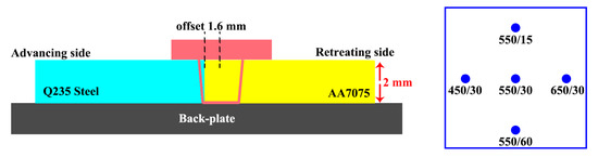
Figure 1.
The FSW schematic diagram and the FSW parameters employed in this work.
After FSW, both the metallurgical and mechanical samples were cut vertically to the welding direction. The Optical Microscope (OM, Olympus DSX-500) was used to observe the cross-sections of the dissimilar Al/steel joints and evaluate the welding quality of FSW. The OM samples were mechanically polished and etched with Keller’s reagent (for the AA7075 side) and a solution of 96 mL ethanol and 4 mL nitric acid (for the Q235 steel side). Furthermore, the Scanning Electron Microscope (SEM, FEI Quanta-600) was utilized to characterize the morphologies of the IMC layers and the steel fragments, and all the SEM samples were only mechanically polished without etching. Additionally, in order to investigate both the diffusion between Al/steel and the compositions of the IMC layers, the Energy Dispersive Spectroscopy (EDS) was employed. The welding strength of the dissimilar Al/steel joints was assessed by the hardness and ultimate tensile strength (UTS). The Vickers hardness test (HV, FUTURE-Tech) was performed along the middle of the cross-section with a load of 100 gf for 5 s, and moreover, the measured distance between the neighboring points was kept at 0.5 mm. The tensile test (TS, Instron-5969) was carried out at room temperature, and the cross-head speed was set to 1.5 mm/min. The gauge length and gauge width of the tensile specimens were 25 mm and 10 mm, respectively. After tensile test, the fracture surfaces of the tensile specimens were detected with SEM. For both the Vickers hardness and tensile tests, all the FSW joints were tested three times for the obtaining of averages in data.
3. Results and Discussion
Figure 2a shows the initial microstructures of Q235 steel, which comprises ferrite and pearlite; the shape of the ferrite grains is irregular and the pearlite is located between the boundaries of the ferrite grains. For the BM of AA7075, the grains are elongated and coarse (Figure 2b), and moreover, some Fe-Cu contains particles are distributed in the Al matrix (Figure 2c). Based on the research of Su et al. [20], these Fe-Cu particles are in the Al7Cu2Fe phase, which is thermostable on account of its high dissolution point.
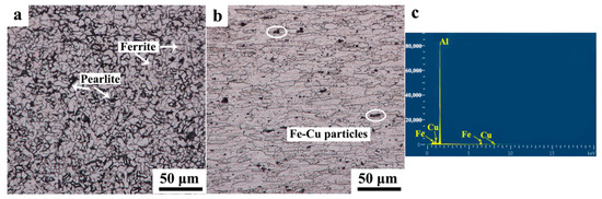
Figure 2.
The microstructures in the BM of (a) Q235 and (b) AA7075 and (c) the EDS analysis of Fe-Cu particles in the matrix of AA7075.
Figure 3 shows a top view of all the FSW joints; the periodic arc feature can be seen on the surface of the joints, indicating that the AA7075 and Q235 commingle during FSW. No macro-defects such as grooves can be found, and it appears that all the FSW parameters applied in this work are reasonable.
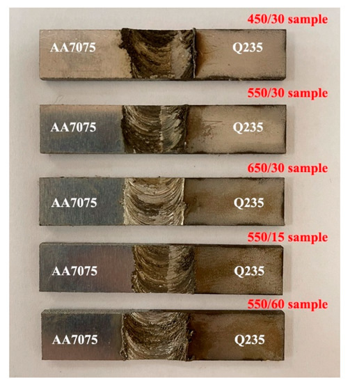
Figure 3.
The top views of the FSW joints in this work.
The cross-sections of the dissimilar Al/steel joints using different FSW parameters are shown in Figure 4. AA7075 and Q235 steel are successfully joined and distinct NZ can be observed for all the FSW joints. The initial Al/steel interface is destroyed and becomes curved after FSW, and large amounts of steel fragments are inserted into the NZ and mix with the Al matrix. The morphologies of the steel fragments in the NZ vary depending on the FSW parameters, and a further analysis is conducted with SEM. During FSW, pieces of the steel break and are stirred into the NZ; in the 450/30 sample, the fine steel particles are mainly located adjacent to the Al/steel interface, and some large steel strips can also be found (Figure 5a). In contrast, increasing the rotational speed (from 450 rpm to 550 rpm) enhances the stirring behavior of FSW, pulling the steel fragments (both the fine steel particles and the large steel strips) further away from the Al/steel interface (Figure 5b). The stirring behavior appears to be sufficient for the 650/30 sample, and as a result, the distribution of the steel fragments became more homogeneous and all the large steel strips break into fine particles (Figure 5c). Apart from the rotational speed, decreasing the welding speed (from 30 mm/min to 15 mm/min) also contributes to the refinement of the steel fragments (Figure 5d). On the contrary, the high welding speed (60 mm/min) weakens the stirring behavior, as the large steel blocks cannot break sufficiently and gather adjacent to the Al/steel interface (Figure 5e). In addition, micro-defects are detected in the joints of 450/30 (Figure 5a1) and 550/60 (Figure 5e1). It is known that the welding heat input is proportional to ω2/v (i.e., the heat index), where ω is the rotational speed and v is the welding speed [21,22]. The calculated results of the heat index are listed in Table 2, which indicates that the micro-defects arise in the joints fabricated under the cold FSW condition. For both the 450/30 and 550/60 samples, the formation of the micro-defects can be explained with the following two reasons: (I) the material flow becomes inadequate due to the cold FSW condition, and then the micro-voids left by the stir tool cannot be filled entirely [23]; (II) the large steel strips/blocks disturb the material flow [15], and the chaotic flow field deteriorates the formability of FSW. The welding quality is summarized in Figure 5f, and it can be concluded that the 550/15, 550/30 and 650/30 samples are sound, while cavities form in the 450/30 and 550/60 samples.
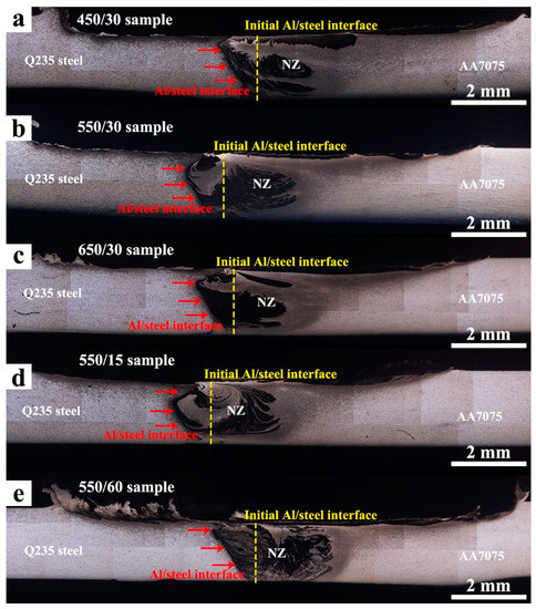
Figure 4.
The cross-sections of the (a) 450/30, (b) 550/30, (c) 650/30, (d) 550/15, and (e) 550/60 samples observed with OM (yellow dotted line: the initial Al/steel interface, red arrows: the Al/steel interface after FSW).
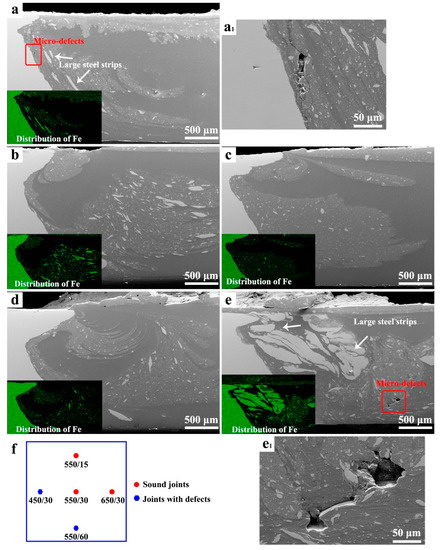
Figure 5.
The morphologies in the NZs of the (a) 450/30, (b) 550/30, (c) 650/30, (d) 550/15, and (e) 550/60 samples detected with SEM; and the magnified images of the micro-defects in the (a1) 450/30 and (e1) 550/60 samples; (f) the quality of all the FSW joints.
Table 2.
The results of the heat index calculated in this work.
The tone of Q235 steel under SEM detection is bright, while that of AA7075 is dark; and some grey regions can also be found. The difference in tone indicates that the chemical compositions of the grey regions are different from that of AA7075/Q235 steel, which is supposed to be the IMC layers. As shown in Figure 6, the IMC layers generate along the Al/steel interface in all the FSW samples, and the characteristics of IMC layers are analyzed with the EDS line/spot scan.
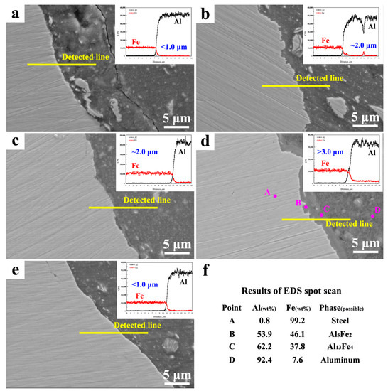
Figure 6.
The characteristics of the IMC layers in the (a) 450/30, (b) 550/30, (c) 650/30, (d) 550/15 and (e) 550/60 sample, (f) the EDS spot scan results of IMC layers in the 550/15 sample.
It has been reported that the thickness of IMC layers can be predicted by (Dt)1/2, where D is the diffusion coefficient of Fe into Al and Al into Fe, and t is the time duration when the FSW temperature is higher than the temperature of the Al/steel diffusion [24]. In our work, both the D and the temperature of Al/steel diffusion are similar for all the FSW samples, while t is controlled by the heat index. A large heat index increases both the FSW temperature and t, and as a result, the IMC layers become thick. In contrast, the cold FSW condition of the 450/30 sample shortens t, which inhibits the diffusion between Al and steel. Thus, the IMC layers in the 450/30 sample become discontinuous and the thickness is less than 1.0 μm (Figure 6a). Furthermore, the inadequate material flow and chaotic flow field deteriorate the formability of the 450/30 sample, and a crack can be found adjacent to the IMC layers. Increasing the welding heat input/heat index promotes the Al/steel diffusion, and the thickness of the IMC layers increases to ~2.0 μm for the 550/30 and 650/30 samples (Figure 6b,c). Unfortunately, the relatively high welding heat input of the 550/15 sample leads to the excessive growth of the IMC layers (more than 3 μm thick), as shown in Figure 6d. In this work, the IMC layers mainly comprise the Al5Fe2 and Al13Fe4 phases (Figure 6f). And similar compositions of the IMC layers were detected by Wang et al. [25]; they stated that the Al13Fe4 nucleated first and then the Al5Fe2 generated via the subsequent diffusion of Fe into the Al13Fe4. As the welding heat input decreases, the thickness of the IMC layers again reduces below 1.0 μm for the 550/60 sample (Figure 6e). Except for the Al/steel interface, the IMC layers are also observed surrounding the steel fragments in the NZ (Figure 7a). These IMC layers grow by consuming the steel inside and separating the large steel fragments into pieces (Figure 7b).
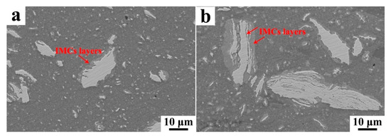
Figure 7.
The IMC layers (a) surrounding and (b) separating the broken steel particles in the NZ.
Compared with the initial coarse grains in the BM, the Al in the NZ is refined due to the dynamic recrystallization (DRX) caused by FSW (Figure 8a) [26]. Furthermore, the final DRX grain size increases along with the welding heat input [27], thus the grains of the 450/30 and 550/30 samples (Figure 8b,c) are smaller than those of the 650/30 and 550/15 samples (Figure 8d,e). On the contrary, both the DRX region with fine Al grains and the non-DRX region with elongated Al grains can be detected in the 550/60 sample (Figure 8f). This might be related to the existence of the large steel blocks in the NZ: the resistance to deformity of the large steel blocks is relatively high, and thus, the Al surrounded by these steel blocks cannot be stirred sufficiently during FSW, inhibiting the DRX of Al. In contrast, for the regions lacking the large steel blocks, Al undergoes severe plastic deformation and gives rise to the occurrence of DRX.
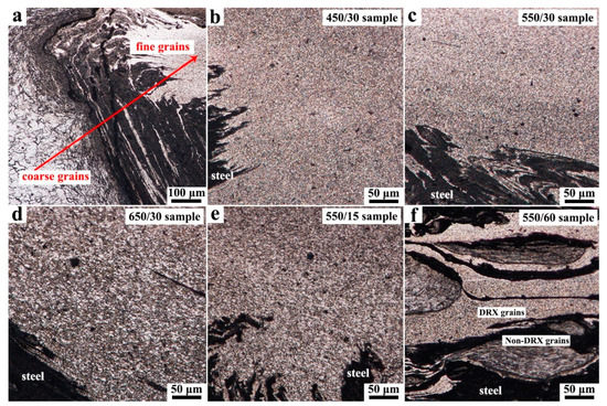
Figure 8.
(a) The evolution of grain from BM to NZ, the grains in the NZs of the (b) 450/30, (c) 550/30, (d) 650/30, (e) 550/15, and (f) 550/60 samples.
The results of the Vickers hardness test are shown in Figure 9a; the hardness of the NZ improves for all the FSW samples. The high level of the hardness in the NZ is attributed to two strengthening mechanisms: (I) the refined microstructures contribute to the grain-boundary strengthening [28], and (II) the steel fragments lead to the precipitation strengthening [29]. However, the distribution and size of steel fragments in the NZ is not sufficiently uniform, which results in the fluctuation of the hardness. All the FSW joints are failed inside the NZ and the corresponding tensile strengths (i.e., UTS) are shown in Figure 9b. The differences in UTS among the 450/30, 550/30, and 550/15 samples are mainly caused by the different thicknesses of the IMC layers: the IMC layers of the 450/30 sample are thin and discontinuous, weakening the metallurgical bonding between the Al and the steel. Therefore, the UTS of the 450/30 sample is relatively low (less than 50 MPa). In comparison, the IMC layers in the 550/30 sample grew and reached the optimal-thickness proposed by refs [12,13] (i.e., 2 μm), increasing the UTS to about 80 MPa. As mentioned in refs [10,11], the IMC layers should not be too thick, and this can explain the reduced UTS of the 550/15 sample. In addition, it should be noted that the thickness of IMC layers in the 550/30 and 650/30 samples is similar, while a 20 MPa increment in the UTS is still obtained for the 650/30 sample. The increment is caused by the finer steel fragments in the 650/30 sample; the large steel strips embedded in the matrix easily cause the stress concentration during tensile test [30,31] and limits the utmost bearing capacity of the 550/30 sample. In summary, the morphologies of the IMC layers and steel fragments should be controlled simultaneously; otherwise, too thin or too thick IMC layers (i.e., the 450/30 and 550/15 samples) and/or large steel blocks (i.e., the 550/60 samples) will deteriorate the welding strength.
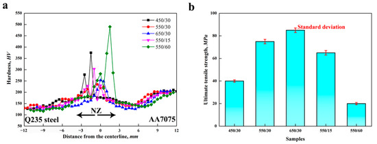
Figure 9.
(a) The hardness profiles and (b) ultimate tensile strengths of all the FSW joints.
The images of the fracture tensile specimens are shown in Figure 10; all the joints are failed without obvious necking. The fracture occurs inside the NZ and close to the Al/steel interface (Figure 10a–e). For the samples produced under the cold FSW condition (i.e., the 450/30 and 550/60 samples), large steel strips/blocks are pulled out of Al matrix during tensile test, and then the left cavities of steel can be defected on the fracture surface (Figure 10f,j). In contrast, the fracture surfaces of other samples are relatively flat without the cavities, indicating that the specimens fail along the IMC layers (Figure 10g–i). Unfortunately, the elongation is less than 5% for all the FSW samples, the fracture mode is brittle, and no dimples can be found (Figure 11). Hence, much work remains to obtain ductile joints.
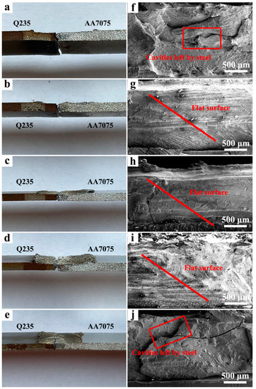
Figure 10.
The fracture surfaces of the (a,f) 450/30, (b,g) 550/30, (c,h) 650/30, (d,i) 550/15, and (e,j) 550/60 samples.
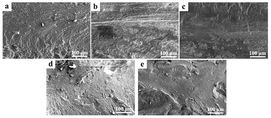
Figure 11.
The fracture model images of the (a) 450/30, (b) 550/30, (c) 650/30, (d) 550/15, and (e) 550/60 samples.
4. Conclusions
The characteristics of the dissimilar AA7075/Q235 steel joints made by FSW were investigated, and the following results were obtained:
(1) During FSW, the Al grains undergo refinement and the steel fragments are stirred into the NZ. Moreover, the IMC layers generate along the Al/steel interface and grow as the welding heat input increases. Under the cold FSW condition, the material flow becomes weak and the large steel stripes/blocks disturb the flow field, resulting in the formation of micro-defects. Meanwhile, the grain refinement of Al is also inhomogeneous under the cold FSW condition. The DRX of Al only occurs in the regions lacking the large steel blocks.
(2) Compared with the initial BM, the grain boundary/precipitation strengthening caused by the refined microstructures increases the hardness of NZ. And the welding strength is mainly affected by both the thickness of the IMC layers and the size of the steel fragments; the optimal-thickness IMC layers (i.e., 2 μm) and fine steel particles are required in order to improve the UTS of the FSW joints. Finally, all the joints fail inside the NZ and two kinds of fracture surfaces are observed: one is flat along the Al/steel interface and the other is uneven due to the pulling out of the large steel strips/blocks.
Author Contributions
Conceptualization, Y.C. and F.Z.; methodology, Y.C.; investigation, Y.C.; writing—original draft preparation, Y.C.; writing—review and editing, Y.C. and F.Z.; project administration, Y.C.; funding acquisition, Y.C. All authors have read and agreed to the published version of the manuscript.
Funding
This research was funded by National Natural Science Foundation of China (Grant No. 52005090), Natural Science Foundation of Liaoning Province (Grant No. 2020-BS-051), Fundamental Research Funds for the Central Universities of China (Grant No. N2103012) and National Defense Key Disciplines Laboratory of Light Alloy Processing Science and Technology, Nanchang Hangkong University (Grant No. EG202080409).
Institutional Review Board Statement
Not applicable.
Informed Consent Statement
Not applicable.
Data Availability Statement
Data are contained within the article.
Acknowledgments
Thanks for the technical supporting of Yuqing Mao, who is working in the National Defense Key Disciplines Laboratory of Light Alloy Processing Science and Technology, Nanchang Hangkong University.
Conflicts of Interest
The authors declare no conflict of interest.
References
- Liu, X.; Lan, S.H.; Ni, J. Electrically assisted friction stir welding for joining Al 6061 to TRIP 780 steel. J. Mater. Process Technol. 2015, 219, 112–123. [Google Scholar] [CrossRef]
- Ramachandran, K.K.; Murugan, N.; Kumar, S.S. Effect of tool axis offset and geometry of tool pin profile on the characteristics of friction stir welded dissimilar joints of aluminum alloy AA5052 and HSLA steel. Mater. Sci. Eng. A 2015, 639, 219–233. [Google Scholar] [CrossRef]
- Pourali, M.; Abodollah-zadeh, A.; Saeid, T.; Kargar, F. Influence of welding parameters on intermetallic compounds formation in dissimilar steel/aluminum friction stir welds. J. Alloy. Compd. 2017, 715, 1–8. [Google Scholar] [CrossRef]
- Mahto, R.P.; Bhoje, R.; Pal, S.K.; Joshi, H.S.; Das, S. A study on mechanical properties in friction stir lap welding of AA6061-T6 and AISI 304. Mater. Sci. Eng. A 2016, 652, 136–144. [Google Scholar] [CrossRef]
- Bokov, D.O.; Jawad, M.A.; Suksatan, W.; Abdullah, M.E.; Swierczynska, A.; Fydrych, D.; Derazkola, H.A. Effect of pin shape on thermal history of aluminum-steel friction stir welded joint: Computational fluid dynamic modeling and validation. Materials 2021, 14, 7883. [Google Scholar] [CrossRef]
- Tanaka, T.; Morishige, T.; Hirata, T. Comprehensive analysis of joint strength for dissimilar friction stir welds of mild steel to aluminum alloys. Scripta Mater. 2009, 61, 756–759. [Google Scholar] [CrossRef]
- Bergmann, L.A.; Batistao, B.F.; Alcantara, N.G.D.; Gargarella, P.; Klusemann, B. Effect of rotational speed and double-sided welding in friction stir-welded dissimilar joints of aluminum alloy and steel. Weld. World 2022, in press. [Google Scholar] [CrossRef]
- Chen, Y.; Zhang, F.H. Improving the quality of dissimilar Al/Steel butt-lap joint via ultrasonic-assisted friction stir welding. Materials 2022, 15, 1741. [Google Scholar] [CrossRef]
- Uzun, H.; Donne, C.D.; Argagnotto, A.; Ghidini, T.; Gambaro, C. Friction stir welding of dissimilar Al 6013-T4 to X5CrNi18-10 stainless steel. Mater. Des. 2005, 26, 41–46. [Google Scholar] [CrossRef]
- Bozzi, S.; Etter-Helbert, A.L.; Baudin, T.; Criqui, B.; Kerbiguet, J.G. Intermetallic compounds in Al 6016/IF-steel friction stir spot welds. Mater. Sci. Eng. A 2010, 527, 4505–4509. [Google Scholar] [CrossRef]
- Hussein, S.A.; Tahir, A.S.M.; Hadzley, A.B. Characteristics of aluminum-to-steel joint made by friction stir welding: A review. Mater. Today Commun. 2015, 5, 32–49. [Google Scholar] [CrossRef]
- Movahedi, M.; Kokabi, A.H.; Reihani, S.M.S.; Najafi, H. Effect of tool travel and rotation speeds on weld zone defects and joint strength of aluminum steel lap joints made by friction stir welding. Sci. Technol. Weld Join 2012, 17, 162–167. [Google Scholar] [CrossRef]
- Lee, C.Y.; Choi, D.H.; Yeon, Y.M.; Jung, S.B. Dissimilar friction stir spot welding of low carbon steel and Al-Mg alloy by formation of IMC. Sci. Technol. Weld. Join 2013, 14, 216–220. [Google Scholar] [CrossRef]
- Abd Elnabi, M.M.; Osman, T.A.; El Mokadem, A.; Elshalakany, A.B. Evaluation of the formation of intermetallic compounds at the intermixting lines and in the nugget of dissimilar steel/aluminum friction stir welds. J. Mater. Res. Technol. 2020, 9, 10209–10222. [Google Scholar] [CrossRef]
- Choi, J.W.; Liu, H.H.; Fujii, H. Dissimilar friction stir welding of pure Ti and pure Al. Mater. Sci. Eng. A 2018, 730, 168–176. [Google Scholar] [CrossRef]
- Moon, C.; Thuilier, S.; Lee, J.W.; Lee, M.G. Mechanical properties of solution heat treated Al-Zn-Mg-Cu (7075) alloy under different cooling conditions: Analysis with full field measurement and finite element modeling. J. Alloys Compd. 2021, 856, 158180. [Google Scholar] [CrossRef]
- Wang, H.D.; Wang, K.S.; Wang, W.; Huang, L.Y.; Peng, P.; Yu, H.L. Microstructure and mechanical properties of dissimilar friction stir welded type 304 austenitic stainless steel to Q235 low carbon steel. Mater. Charact. 2019, 155, 109803. [Google Scholar] [CrossRef]
- Chen, Y.; Cai, Z.H.; Ding, H.; Zhang, F.H. Characteristics of dissimilar aluminum/steel joint fabricated via self-riveting friction stir lap welding. Trans. Indian Inst. Met. 2021, 74, 2621–2629. [Google Scholar] [CrossRef]
- Dehghani, M.; Akbari-Mousavi, S.A.A.; Amadeh, A. Effects of parameters and tool geometry on properties of 3003-H18 aluminum alloy to mild steel friction stir weld. Trans. Nonferrous. Met. Soc. China 2013, 23, 1957–1965. [Google Scholar] [CrossRef]
- Su, J.Q.; Nelson, T.W.; Mishra, R.; Mahoney, M. Microstructural investigation of friction stir welded 7050-T651 aluminum. Acta Mater. 2003, 51, 713–729. [Google Scholar] [CrossRef]
- Chen, Y.; Ding, H.; Li, J.Z.; Zhao, J.W.; Fu, M.J.; Li, X.H. Effect of welding heat input and post-welded heat treatment on hardness of stir zone for friction stir-welded 2024-T3 aluminum alloy. Trans. Nonferrous. Met. Soc. China 2015, 25, 2524–2532. [Google Scholar] [CrossRef]
- Fu, R.D.; Zhang, J.F.; Li, Y.J.; Kang, J.; Liu, H.J.; Zhang, F.C. Effect of welding heat input and post-welding natural aging on hardness of stir zone for friction stir-welded 2024-T3 aluminum alloy thin-sheet. Mater. Sci. Eng. A 2013, 559, 319–324. [Google Scholar] [CrossRef]
- Chen, Y.; Wang, H.; Wang, X.Y.; Ding, H.; Zhao, J.W.; Zhang, F.H.; Ren, Z.H. Influence of tool pin eccentricity on microstructural evolution and mechanical properties of friction stir processed Al-5052 alloy. Mater. Sci. Eng. A 2019, 739, 272–276. [Google Scholar] [CrossRef]
- Wang, T.H.; Shukla, S.; Gwalani, B.; Komarasamy, M.; Reza-Nieto, L.; Mishra, R.S. Effect of reactive alloy elements on friction stir welded butt joints of metallurgically immiscible magnesium alloys and steel. J. Manuf. Process 2019, 39, 138–145. [Google Scholar] [CrossRef]
- Wang, T.H.; Sidhar, H.; Mishra, R.S.; Hovanski, Y.R.; Upadhyay, P.; Carlson, B. Evaluation of intermetallic compound layer at aluminum/steel interface joined by friction stir scribe technology. Mater. Des. 2019, 174, 107795. [Google Scholar] [CrossRef]
- Su, J.Q.; Nelson, T.W.; Sterling, C.J. Microstructure evolution during FSW/FSP of high strength aluminum alloys. Mater. Sci. Eng. A 2005, 405, 277–286. [Google Scholar] [CrossRef]
- Azimzadegan, T.; Serajzadeh, S. An investigation into microstructures and mechanical properties of AA7075-T6 during friction stir welding ta relatively high rotational speeds. J. Mater. Eng. Perform. 2010, 19, 1256–1263. [Google Scholar] [CrossRef]
- Malopheyev, S.; Kulitskiy, V.; Mironov, S.; Zhemchuzhnikova, D.; Kaibyshev, R. Friction-stir welding of an Al-Mg-Sc-Zr alloy in as-fabricated and work-hardened conditions. Mater Sci Eng A 2014, 600, 159–170. [Google Scholar] [CrossRef]
- Batistao, B.F.; Bergmann, L.A.; Gargarella, P.; De-Alcantara, N.G.; Dos-Santos, J.F.; Klusemann, B. Characterization of dissimilar friction stir welded lap joints of AA5083 and GL D36 steel. J. Mater. Res. Technol. 2020, 9, 15132–15142. [Google Scholar] [CrossRef]
- Wang, B.X.; Yi, Y.P.; He, H.L.; Huang, S.Q. Effects of deformation temperature on second-phase particles and mechanical properties of multidirectionally-forged 2A14 aluminum alloy. J. Alloys Compd. 2021, 871, 159459. [Google Scholar] [CrossRef]
- Mao, Y.Q.; Yang, P.; Ke, L.M.; Xu, Y.; Chen, Y.H. Microstructure evolution and recrystallization behavior of friction stir welded thick Al-Mg-Zn-Cu alloys: Influence of pin centerline deviation. Acta Metall. Sin. 2021, 35, 745–756. [Google Scholar] [CrossRef]
Publisher’s Note: MDPI stays neutral with regard to jurisdictional claims in published maps and institutional affiliations. |
© 2022 by the authors. Licensee MDPI, Basel, Switzerland. This article is an open access article distributed under the terms and conditions of the Creative Commons Attribution (CC BY) license (https://creativecommons.org/licenses/by/4.0/).