Article

Strength and Fatigue Life at 625 K of the Ultrafine-Grained Ti-6Al-4V Alloy Produced by Equal-Channel Angular Pressing

by
Irina P. Semenova
1,*,
Alexander V. Polyakov
1,2,
Mikhail V. Pesin
2,
Andrey G. Stotskiy
1,3,
Yulia M. Modina
1,3,
Ruslan Z. Valiev
3 and
Terence G. Langdon
4
1
Laboratory of Multifunctional Materials, Bashkir State University, St. Zaki Validi, 32, 450008 Ufa, Russia
2
Department of Mechanical Engineering Innovative Technologies, Perm National Research Polytechnic University, 29 Komsomolsky Pr., 614990 Perm, Russia
3
Institute of Physics of Advanced Materials, Ufa State Aviation Technical University, 12 K. Marx St., 450008 Ufa, Russia
4
Materials Research Group, Department of Mechanical Engineering, University of Southampton, Southampton SO17 1BJ, UK
*
Author to whom correspondence should be addressed.
Metals 2022, 12(8), 1345; https://doi.org/10.3390/met12081345
Submission received: 30 June 2022 / Revised: 9 August 2022 / Accepted: 9 August 2022 / Published: 12 August 2022

Abstract

:
Grain reduction in a widely used Ti-6Al-4V alloy increases its endurance limit at room temperature. In this work, the behavior of the ultrafine-grained alloy under cyclic load at the temperature of 625 K is considered. Research was conducted to examine the fatigue life in a low-cycle area of the ultrafine-grained Ti-6Al-4V alloy produced by equal-channel angular pressing. Tensile and fatigue testing of the Ti-6Al-4V samples with coarse-grained (CG) and ultrafine-grained (UFG) structures were carried out at 293 and 625 K. The alloy demonstrated an enhanced strength and fatigue life at both temperatures. The representative features of the microstructural evolution and the fracture features in the UFG and CG alloys after fatigue tests are described in detail. The prospects for the use of the UFG Ti-6Al-4V alloy for engineering applications, such as in the production of critical gas-turbine engine parts, is discussed.

1. Introduction

Alloys such as Ti-6Al-4V (i.e., two-phase α + β titanium alloys) are widely applied in aviation and engine building due to their high-specific strength and corrosion resistance [1,2]. Fatigue fracture resistance is one of the key characteristics of structural materials. Nevertheless, increasing their fatigue limit remains a relevant task in the development and production of heavy-loaded gas-turbine engine (GTE) parts, such as compressor blades and disks, which experience substantial alternating tensile loads during operation.
It is known that the fatigue properties of Ti alloys strongly depend on the microstructure, the surface condition of the samples and the test conditions [2,3]. Traditionally, an increase in the fatigue characteristics of Ti alloys is achieved by means of increasing the ultimate tensile strength through alloying or varying the structural and phase composition by thermal and thermomechanical treatment. This may produce microstructures of different morphologies (equiaxed, lamellar, mixed, etc.) [2,3,4], but in most cases these approaches have exhausted their capabilities. As demonstrated by recent studies, the formation of a bulk ultrafine-grained (UFG) structure (grain size within 1 μm) in metals by severe plastic deformation (SPD) processing provides the potential of significantly improving their mechanical properties at room temperature [5,6,7,8,9,10,11,12]. The Ti and Ti-6Al-4V alloy are the best studied in publications over the last 20 years, and most of these publications show that the formation of a submicrocrystalline or UFG structure leads to an increase in the fatigue limit at room temperature [13,14,15,16,17,18,19,20,21,22,23]. In particular, in a paper by Zherebtsov et al., high-cycle fatigue tests for 106 cycles under bending with rotation of the samples from the conventional coarse-grained (CG) and submicrocrystalline (SMC) Ti-6Al-4V alloys processed by multiple forging revealed an increase in fatigue limit by approximately 17% [14]. Saitova et al. investigated in detail the Ti-6Al-4V ELI alloy samples in the CG and UFG states, produced by equal-channel angular pressing (ECAP), in the high-cycle and low-cycle fatigue regions at room temperature [21]. It was shown that the behavior of the alloy in both states in the low-cycle fatigue region corresponded quite well to the Coffin–Manson relation ∆εpl/2 = εf(2Nf)c, where ∆εpl/2 is the plastic strain amplitude, εf is the fatigue ductility coefficient, 2Nf is the number of cycles to failure, and c is the fatigue ductility exponent. These papers showed that in the investigated amplitude range of plastic strain from 10−2 to 2 × 10⁻⁵, the fatigue ductility exponent c remained practically identical for the CG and UFG materials which had previously been observed in UFG Ti [13]. In addition, the total fatigue life of the UFG alloy in Wöhler’s curves was higher than that of the CG alloy; the curves did not intersect in the region of the investigated strains; and the increment in the fatigue limit of the UFG alloy was about 15% [21].
It is known that aircraft engine components experience complex loads. For example, a typical loading pattern of GTE blades or disks consists of low frequencies and high amplitudes of stresses (low-cycle fatigue) with periodically resonant high-frequency loads under relatively high medium loads (high-cycle fatigue) [24]. Besides, it is known that the operating temperature of GTE parts made of the Ti-6Al-4V alloy, such as compressor blades, may vary from 475 to 625 K. This requires an evaluation of their mechanical behavior at elevated temperatures for the engineering applications of UFG Ti alloys [1]. In this area, there were a number of studies of the UFG Ti-6Al-4V alloy, in particular, of its short-term and long-term strength at operating temperatures [25,26,27]. Thus, the studies performed to date have already demonstrated the possibility in principle of applying the Ti-6Al-4V alloy in the UFG state to the production of gas-turbine engine parts operating in the conditions of high cyclic loads and elevated temperatures. However, so far there have been no studies of the fatigue strength of the Ti-6Al-4V alloy in the UFG state at operating temperatures.
The present research was undertaken with a view to evaluate the prospects of engineering applications of the UFG alloy at elevated temperatures. We studied the fatigue properties of the CG and UFG Ti-6Al-4V alloy at an operating temperature of 625 K, the maximum possible for this alloy, and we examined features of the microstructure degradation and fracture after fatigue testing.

2. Materials and Methods

The experiments were conducted using hot-rolled rods of the Ti-6Al-4V alloy with a diameter of 20 mm. The alloy had the chemical composition presented in Table 1. The rods were subjected to the standard heat treatment (HT) that consisted of quenching from a temperature of 1240 K and subsequent annealing at 950 K for 4 h. This state is further designated as coarse-grained (CG). The rods after HT were processed using the ECAP facility with an angle of 120° in the ECAP abutment at a temperature of T = 925 K and with each rod processed through a total of 4 passes using route BC, in which the rods are rotated by 90° in the same direction between each pass [22].
Tensile mechanical testing was performed at room temperature and at 625 K at a strain rate of 1 × 10⁻³ s−1 on an Instron 5982 (Instron, Buckinghamshire, UK) tensile testing machine. The tensile specimens had cylindrical gauge sections with initial lengths of 15 mm and diameters of 3 mm. To ensure the reproducibility of the data, three specimens were tested for each condition.
All the fatigue test specimens were produced by turning and mechanical polishing to Ra 0.32 μm (Figure 1). Fatigue tests were carried out at a temperature of 625 K using an Instron 8862 (Instron, Buckinghamshire, UK) fatigue testing system. The tests were performed in the stress-controlled asymmetric tension loading (R = 0.1) mode. A range of stresses from 650 to 900 MPa at a frequency of 1 Hz was used for the testing. The test base was no more than 105 cycles. On the whole, 14 and 15 samples were tested in the CG and UFG conditions, respectively.
The microstructures of the material were analyzed by transmission electron microscopy (TEM) in the longitudinal section of the rod. The samples for foils were cut using electrical discharge machining, then mechanically thinned to a thickness of ~100 µm and electro-polished using a TenuPol-5 facility (Struers LLC, Cleveland, OH, USA) with a solution of 5% perchloric acid, 35% butanol and 60% methanol and a polishing temperature within the range of 240 to 255 K. The microstructures were examined using a TEM, JEOL JEM 2100 microscope (Jeol Ltd, Tokyo, Japan) operating with an accelerating voltage of 200 kV. The surface fractographic investigation after cyclic deformation was conducted using a JEOL JSM 6390 scanning electron microscope (SEM) (Jeol Ltd, Tokyo, Japan).
The X-ray diffraction (XRD) analysis was conducted on a Rigaku Ultima IV diffractometer (Rigaku Corp., Akishima-shi, Japan). The samples were examined with CuKα-radiation (40 kV, 30 mA) and the phase composition of the alloy was determined using the Rietveld method. Fitting parameters for CG state of the alloy are Rexp = 3.01, Rwp = 5.50, GOF = 1.83, and for UFG alloy—Rexp = 2.99, Rwp = 4.46, GOF = 1.49.

3. Experimental Results

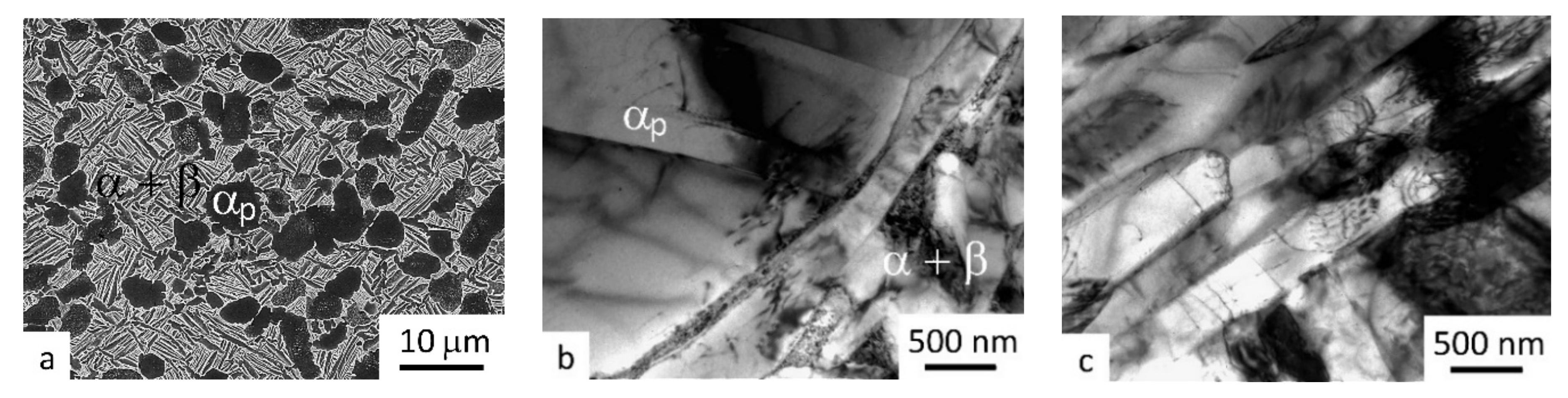
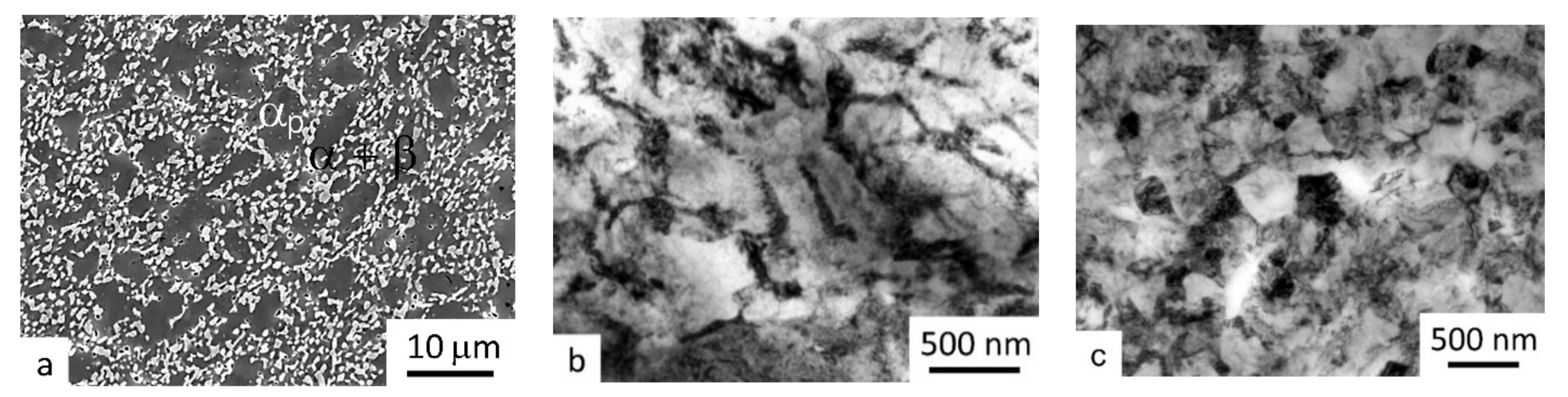
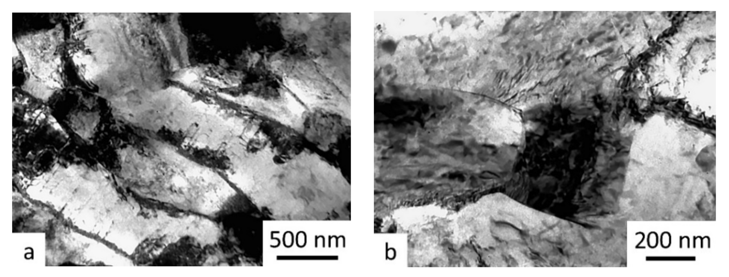
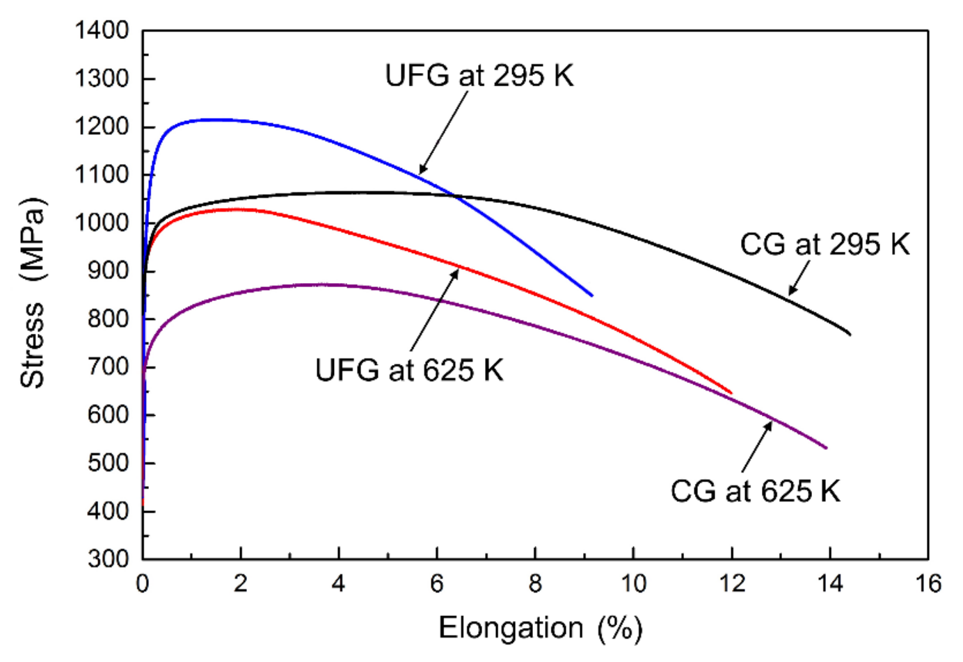
3.1. Microstructure and Mechanical Properties

The microstructure of the rods in the as-received condition represented a deformed mixed globular-lamellar structure typical for the Ti-6Al-4V alloy subjected to hot rolling in the (α + β) region. A view of the initial microstructure of the rod after HT is shown in Figure 2. According to X-ray phase analysis, the ratio between the α- and β-phases was approximately 85%/15%, which is typical for this alloy composition [28]. The volume fraction of coarse grains of the primary α-phase with a size of ~8 μm was about 30% (Figure 2a). In the two-phase α + β regions of the microstructure, colonies of thin α-phase plates with a thickness of about 250 nm were observed (Figure 2b,c).
In the microstructure of the ECAP-processed Ti-6Al-4V alloy, the primary α-phase grains had a distorted shape (Figure 3a) and a weakly developed interior dislocation substructure (Figure 3b), but their size had not changed significantly and on average it was not above 8 μm. The interior regions of the primary α-phase can contain a cellular substructure or twins, depending on their crystallographic orientation with respect to the applied stress direction [29].
In the two-phase α + β regions a UFG structure was formed with a mean grain/subgrain size of about 350 nm, as shown by the TEM images of the structure (Figure 3c). As shown in previous papers, the α-phase plates in the Ti-6Al-4V alloy transformed during the SPD processing at a relatively low temperature by means of the division of the plates by dislocation boundaries, their evolution leading to an increase in their misorientation due to the processes of dynamic recrystallization and spheroidization [29,30,31]. According to X-ray phase analysis, the volume fraction of the β-phase decreased from 15% to 10% due to a partial decomposition of the metastable β-phase during severe plastic deformation [32]. Table 2 presents the mechanical properties at room temperature for the samples after HT and after ECAP processing.
In Figure 4 we should note the difference in the tensile curves for the CG and UFG alloys at room temperature, which indicates a considerable decrease in both total and uniform elongations of the samples after SPD processing. The ultimate tensile strength (UTS) of the UFG alloy reached ~1220 MPa which is ~15% higher than the UTS of ~1040 MPa for the CG heat-treated condition.
Such a mechanical behavior from an UFG alloy indicates an early strain localization and a decline in the strain-hardening capacity at room temperature, which is typical of many materials produced by SPD [5]. Therefore, the tensile curves of UFG specimens usually show a noticeable decrease in the value of uniform elongation (see Figure 4). In the UFG materials, the generation and motion of dislocations are hindered due to the very small grain size and elastic stresses induced by the high-density of dislocations introduced by SPD [33,34,35]. The alloy exhibits similar behavior at 625K, although the UTS decreased in both states, to 890 and 1040 MPa for the CG and UFG states, respectively, through a thermally activated recovery processes.
At the same time, in the UFG sample, the decrease in strength at 625 K is accompanied by a slight increase in the relative total and uniform elongations due to the relaxation of the internal stresses and a decrease in the dislocation density (see Figure 4). This effect is less noticeable in the CG sample, since the relative and uniform elongations practically remained unchanged after the tests at 625 K.

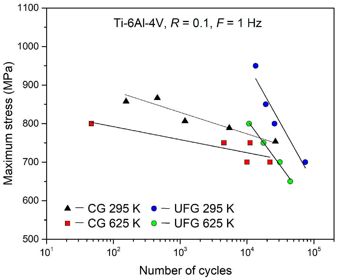
3.2. Fatigue Tests at 625 K

Figure 5 shows the results of the fatigue tests of the Ti-6Al-4V alloy samples with a CG and UFG structure.
Examination of the experimental data at 295 K reveals that there is a difference in the slope of the direct lines for both CG and UFG states, showing the material life with varying maximum stresses. As demonstrated by Figure 5, the life of the UFG alloy at high stresses of 750–900 MPa is much higher than that of its CG counterpart. This is conditioned by the higher UTS of the alloy in the UFG state (Table 2). However, increased the softening more intensively in the UFG alloy than in the CG alloy, as indicated by the difference in the slopes of the curves for the UFG and CG states. For example, at a maximum stress of 700 MPa the CG and UFG samples had practically the same lives (see Figure 5). Apparently, the accumulation of residual strain, leading to failure, is faster for the UFG alloy samples at high stresses (close to yield strength) where processes of elastic-plastic deformation occur [9]. This effect was reported earlier [22], where fatigue tests were carried out under symmetrical cyclic loading (R = −1).
The fatigue resistance decreases for both SC and UFG states at T = 625 K (Figure 5). Thus, the cyclic durability of the alloy decreases at elevated temperatures. At the same time, the UFG alloy withstands a greater number of cycles before failure compared to the CG alloy, especially at stresses above 800 MPa (Figure 5). So, the CG structure withstands 47 cycles and the UFG structure 10,700 at the stress of 800 MPa and 10,000 and 31,101 cycles at 700 MPa for CG and UFG, respectively. It should be noted that the difference in the slope of the curves at T = 625 K for the CG and UFG alloy is retained (Figure 5).

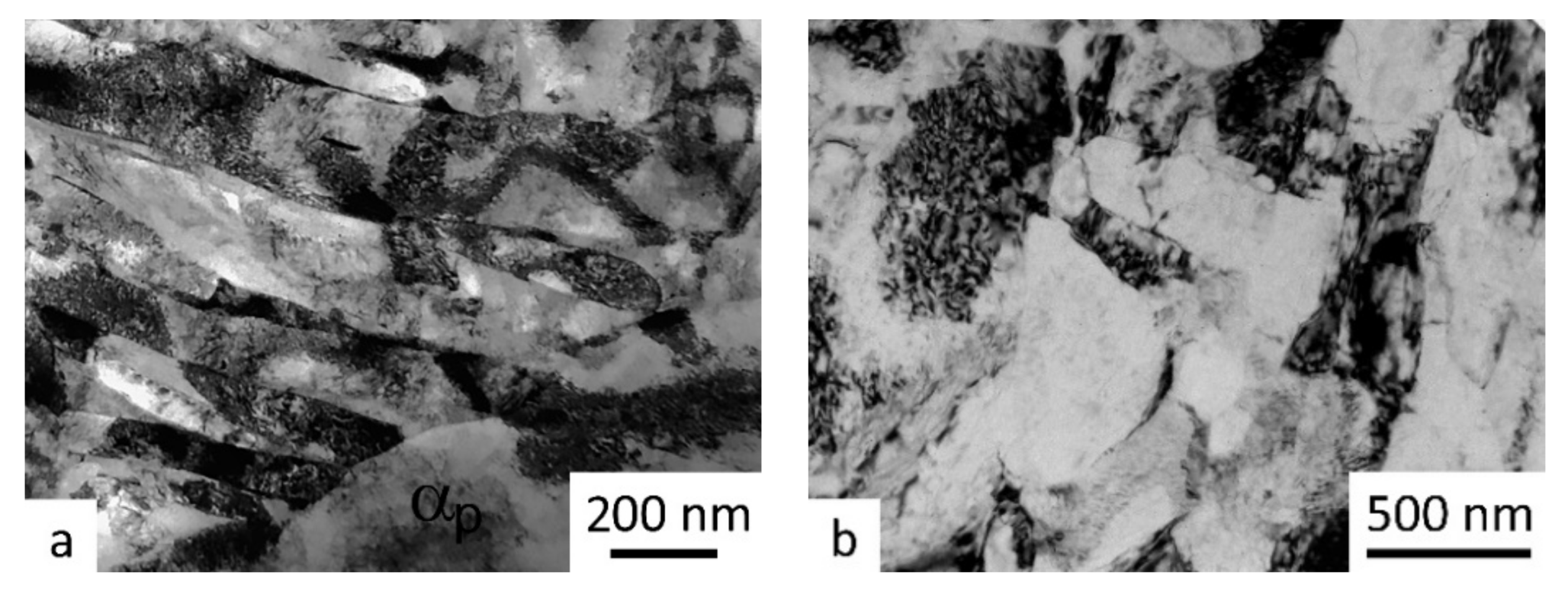
3.3. Microstructure after Fatigue Tests at T = 625 K

The microstructure of the Ti-6Al-4V alloy was studied in the area of fracture of the tested samples. In the CG alloy, after tests at a maximum stress of 700 MPa, dislocation accumulation was observed at the interphase boundaries between the plates and at the boundaries of the primary α-phase (Figure 6a). In the interiors of the α-phase plate complexes, a series of dislocation formations were observed with the development of fragmentation of the α-phase plates. At a higher stress, close to the yield strength of the CG alloy of ~800 MPa, there was no significant difference from the structural evolution at a maximum stress of 700 MPa.
In the UFG state, the structure of the Ti-6Al-4V alloy after tests at a relatively low stress of ~700 MPa exhibited no significant change (Figure 6b). In the separate ultrafine-grains it was possible to observe a decrease in the density of dislocations due to their partial annihilation. A slight coarsening (average grain size is 390 nm) of the ultrafine grains was also observed (cf. Figure 3b and Figure 6b). A decrease in the dislocation density after fatigue tests at room temperature in the UFG sample of the Ti-6Al-4V ELI alloy, revealed by XRD, was noted earlier [36]. In this case, apparently, the reasons for the partial recovery may be several factors related to the initial critically high dislocation density in the ultrafine grains after SPD processing. This tends to hinder the processes of nucleation and accumulation of new dislocations under cyclic deformation, as well as the elevated test temperature, which facilitates the development of thermally activated recovery processes [5].
In the UFG state, as the maximum stress increases to ~900 MPa, the nucleation and redistribution of dislocations lead to their pile-up at the boundaries (Figure 7a) and triple junctions (Figure 7b) of ultrafine grains, as indicated by their clear contrast in the TEM images of the microstructure.

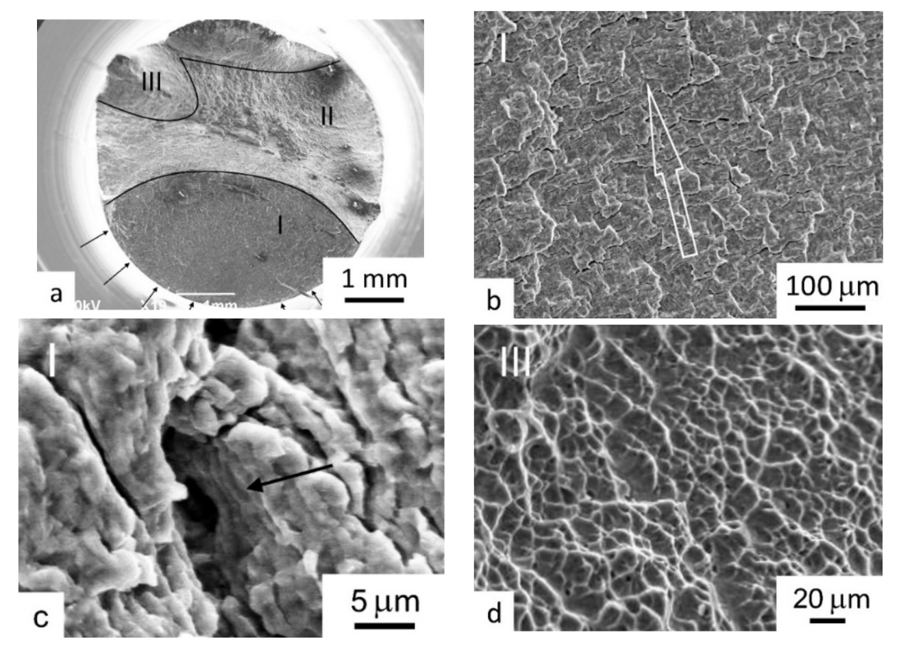
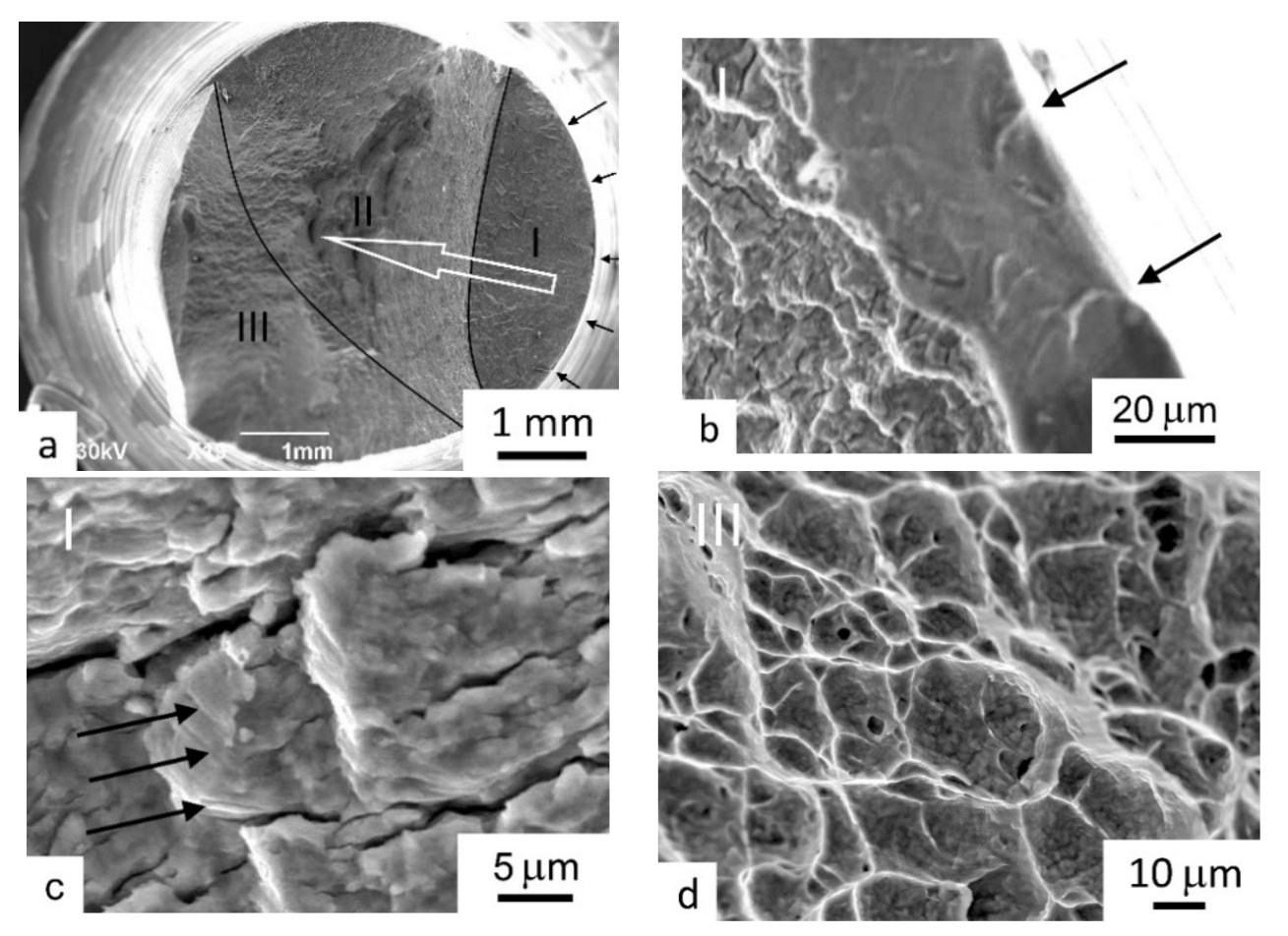
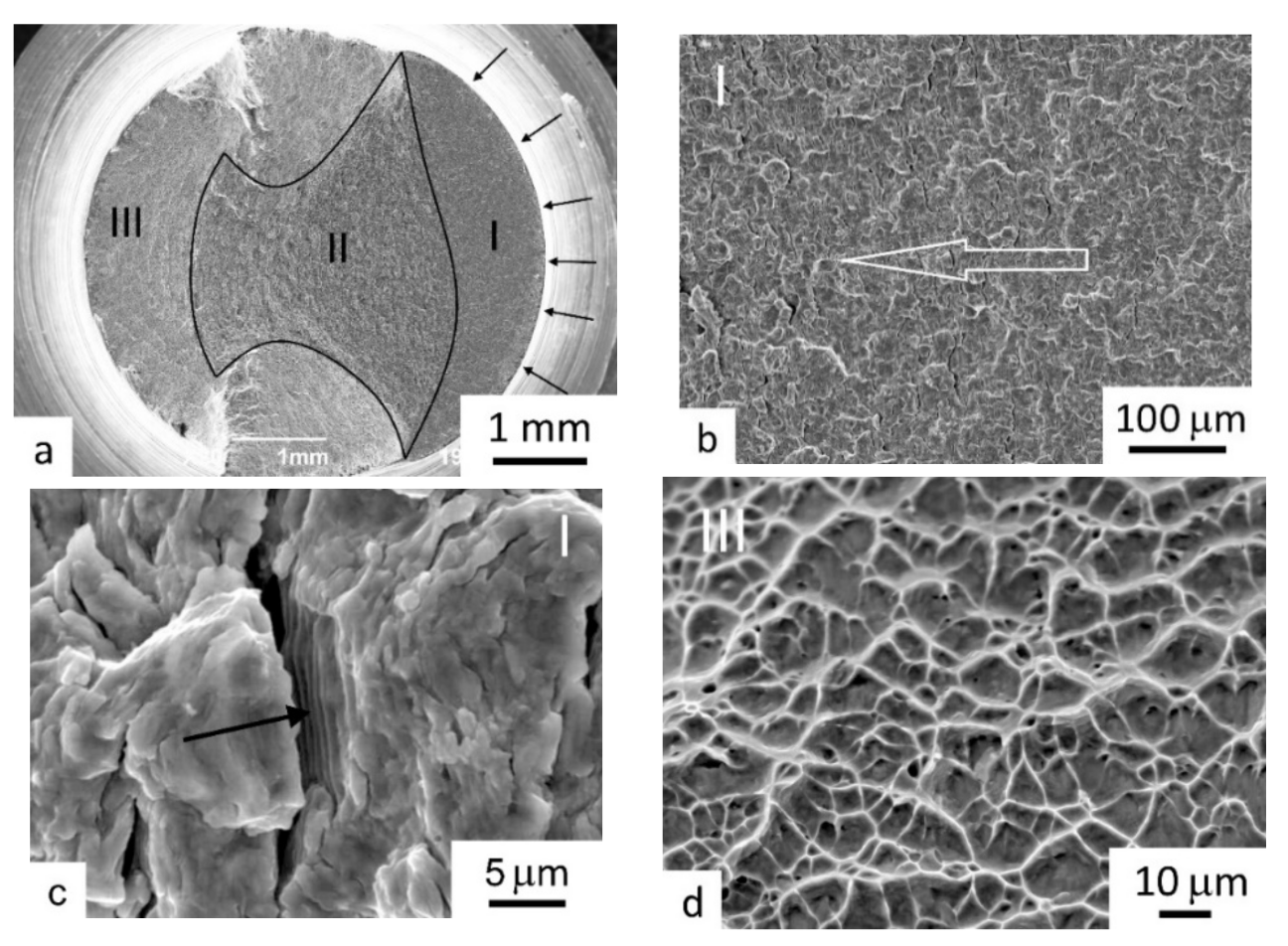
3.4. Fractographic Studies of the Sample Fracture Surfaces at T = 625 K

Figure 8 and Figure 9 show the SEM images of the fracture surfaces of the Ti-6Al-4V alloy samples in the CG and UFG states after tests at a stress of 900 MPa, close to the yield strength of the CG alloy. There was a large difference between the lives of the samples (N = 46 and 9941 cycles to failure for the CG and UFG alloys, respectively).
The fracture surface of the CG Ti-6Al-4V alloy has a cup view (Figure 8a) which is characteristic of quasistatic fracture [37]. Two zones can be distinguished that determine fracture stages, but zone I of stable crack growth is absent. Thus, zone II characterizes the stage of accelerated crack propagation, and zone III is the stage of the final rupture. In stage II, the fracture surface represents a non-uniform cellular-dimple rupture relief with weakly pronounced striations located inside the cells (Figure 8b) whereas zone III has a dimple relief typical of titanium alloys (Figure 8c).
Unlike the CG sample, the fracture surface of the UFG sample after testing has three development stages typical for fatigue fractures of Ti alloys (Figure 9a). Crack initiation is multi-focal, which is typical for LCF, where several microcracks merge into one main crack. Crack initiation takes place at the sample surface, as indicated by the flat areas of shear in Figure 9b. The relief of the stable crack propagation zone (I) is scale-like with microcracks and fatigue striations (Figure 9c). At the accelerated growth stage, large steps of jump-like ruptures are observed (Figure 9a). In the final rupture zone (zone III, Figure 9d), the relief of both samples is represented by a network of dimples uniformly distributed across the surface which is typical for Ti alloys in single rupture [37].
Figure 10 and Figure 11 show the fracture surfaces of the samples of the CG and UFG alloys that were tested at a lower stress of 750 MPa, where their lives were 22,000 and 17,690 cycles for the UFG and CG alloys, respectively.
The fracture surfaces of the samples in both states are characterized by three stages of crack growth, which is typical for fatigue fractures. Thus, there is a zone of crack initiation and stable growth (I), a zone of accelerated crack propagation (II) and an overload zone (III) (Figure 10a and Figure 11a). In both samples, the fatigue-crack initiation occurs with multiple nuclei along the surface where this is typical for the low-cycle fatigue region (see the black arrows in Figure 10a and Figure 11a). It should be noted that the area of stable (slow) fatigue propagation of a crack in the CG sample amounts to about 25% of the sample section whereas in the UFG sample it amounts to almost 40%. Therefore, the region of the fatigue propagation of a crack, including the accelerated growth zone, is much larger in the UFG sample than in the CG sample (Figure 10a and Figure 11a). This directly explains the longer life of the UFG sample, in comparison to the CG sample, when considered at the same stress (750 MPa).
It is important to note that there are some differences in the relief of zone I between the fracture surfaces of the CG and UFG samples. Both samples are characterized by a relatively smoothed-out relief-resembling flakes (Figure 10b and Figure 11b). At the same time, in the CG sample secondary microcracks are located predominantly at interphase boundaries (Figure 10b); in the UFG sample secondary microcracks are located perpendicular to the main crack growth direction (Figure 11b) which has a positive effect in increasing the alloy life. Such a regularity was noted also after the fatigue testing of Ti-6Al-4V ELI alloy samples at room temperature [22]. Figure 10c and Figure 11c show fatigue striations, which indicate a slow propagation of the main crack. The zone of accelerated “jump-like” propagation of the main crack in the UFG sample has a coarser relief than that of the CG sample and the dimple relief alternates with rupture ridges (Figure 10a and Figure 11a). It is noted also that there is an absence of a clear boundary of transition from the zone of fatigue propagation to the final rupture in the UFG sample (Figure 11a). Zone III in both samples has a dimple relief, typical for Ti alloys, that characterizes ductile fractures in single ruptures (Figure 10d and Figure 11d).

4. Discussion

The morphology of phase constituents in titanium alloys has a significant effect on fatigue properties. For example, the best combination of strength, ductility and fatigue strength at HCF is achieved in bimodal two-phase titanium alloys. [2,4,38].
This study shows that UFG samples of Ti-6Al-4V alloy demonstrate increased strength at room temperature due to α-grains refinement and this has already been confirmed by numerous studies [14,15,16,17,20,21,22,23]. As a result, the durability of the UFG alloy at room temperature is higher than it is for the CG alloy. This is evident by the results of testing the samples under asymmetrical cycle loading (R = 0.1) in this work, as well as under symmetric cycle loading (R = −1) from earlier studies [22].
A similar behavior of the UFG alloy was also observed at 625 K. In particular, its ultimate tensile strength became 190 MPa higher than that of the KG analogue (Table 2). The fatigue testing of the UFG samples of the Ti-6Al-4V alloy demonstrates an increased life at an elevated temperature of 625 K compared to the corresponding CG samples, especially at high stresses, as can be seen in Figure 5. At a high maximum stress (900 MPa) the CG sample failed almost immediately (46 cycles), while the UFG sample failed only after 9941 cycles. It is evident that this is directly related to the high strength of the UFG alloy, where the initiation of the first fatigue-cracks occurs much later [9].
Concerning high-cycle tests on the basis of 106 and 107 cycles, several studies demonstrated the possibility of increasing the fatigue limit at room temperature for the Ti-6Al-4V alloy by means of the UFG structure formation [14,17,21,23]. The fatigue limit value of the UFG alloy depends on the processing regime, the geometrical dimensions of the samples and the test conditions such as tension–compression, bending with rotation, cycle symmetry (R), etc. In the high-cycle fatigue region, there was no difference in the curve slopes, unlike in the LCF tests.
Comparing the structural changes in the CG and UFG samples after tests at a temperature of 625 K, similar regularities were found as described earlier where the tests were performed at room temperature [21,22,23]. In the CG structure the dislocation density markedly increased and complex cellular dislocation configurations were formed. On the contrary, in the UFG structure the total dislocation density decreased. At the same time, the average size of the α-phase practically did not change (390 nm after testing versus 350 nm before). This slight coarsening is probably due to the fact that the test temperature is below the recrystallization temperature of the UFG alloy. In the LCF region, the role of the UFG structure became more prominent due to the dislocations interacting more easily with grain boundaries and therefore the slip length attempting to reach the grain size [5,39]. Evidence of this is provided by the fact that in the structure of the UFG samples after tests at a stress of 900 MPa, the nucleation and redistribution of dislocations resulted in their pile-up at the boundaries and triple joints of ultrafine grains (Figure 7). Apparently, under the cyclic action of stresses at an elevated temperature, there occurred competing processes in the nucleation, motion and annihilation of new dislocations both at the boundaries of ultrafine grains and in the grain interiors.
Examining the fracture surface of the CG and UFG samples after fatigue tests, it should be noted that at a stress of 900 MPa, and thus practically at the level of the yield strength of the CG alloy, the fracture surface of the CG samples had a cup view characteristic of single quasistatic rupture [37]. This was also indicated by a very short fatigue life of only 45 cycles (Figure 5). By contrast, the fracture surface relief of the UFG sample was characteristic of a fatigue-crack, and the sample withstood almost 10,000 cycles. This can be attributed to the higher overall strength and the higher yield strength in comparison with the CG sample (~1090 and ~890 MPa, respectively).
At lower stresses of ~750 and ~700 MPa, the difference between the lives of the CG and UFG samples was much smaller at ~22,000 and ~17,690 cycles for the UFG and CG alloys at 750 MPa, respectively. The fracture surface relief of the samples in both structural states was consistent with the classic fatigue fracture (Figure 10 and Figure 11). However, several additional features of the fracture were revealed for the UFG samples. In particular, a larger area of stable crack propagation (25% and 40% for the CG and UFG alloys, respectively) indicated a slower growth of the main crack which made an additional contribution to the increase in the UFG sample life. Also, differences were found in the crack propagation mechanism in the region of stable crack growth (zone I) in the CG and UFG alloys. Thus, the crack propagation mechanism is transcrystalline in both cases. However, dislocation nucleation in the UFG structure took place primarily at the boundaries of ultrafine grains, while dislocation slip in the grain interiors facilitated their accumulation [39]. When a critical stress was reached at the boundaries, further crack propagation occurred within a neighboring grain. Evidence for this is the presence of secondary microcracks in the fracture surface, located perpendicular to the growth direction of the main crack in the UFG sample (Figure 11b). In the CG sample, where the α-phase size is much larger, the main crack propagates at interphase boundaries and in the interiors of the coarse grains of the primary α-phase (Figure 10b). This is in good agreement with the description of the fracture mechanisms active at room temperature in the UFG Ti-6Al-4V ELI alloy [21]. The relief in the zone of accelerated crack propagation (zone II) generally has no significant differences as in the dimple relief in the region of static rupture which is typical for Ti alloys (Figure 10d and Figure 11d).
The fatigue tests performed in this study confirm that an increased fatigue life of the UFG alloy is possible at an operating temperature of 625 K. This agrees with results reported earlier, where the UFG Ti-6Al-4V alloy exhibited an increased fatigue strength in the high-cycle fatigue region (up to 107 cycles) at a temperature of 450 K [25].
However, the real application of UFG Ti alloys in aircraft engine building requires studying a whole range of mechanical properties, including long-term strength at operating temperatures [40,41]. The previously conducted long-term strength tests of the UFG Ti-6Al-4V alloy at operating temperatures (not higher than 350 °C) show its obvious advantage over its coarse-grained counterpart [27]. Therefore, the present work continues a whole series of studies aimed at evaluating the performance characteristics of the Ti-6Al-4V alloy for engineering applications, such as in the production of critical GTE parts, e.g., compressor and fan blades. The first fatigue tests were performed on blades manufactured using the conventional and UFG Ti-6Al-4V alloys [42]. From the test results, it was found that the fatigue endurance limit of the blades with a UFG structure was about 470 MPa, which is almost 30% higher than that of the conventionally manufactured blades.

5. Conclusions

UFG Ti-6Al-4V alloy produced by equal-channel angular pressing exhibited increased tensile strength and fatigue life at an operating temperature of 625 K compared to its CG counterpart.
Regularities were revealed in the changes of the microstructure and dislocation substructure in the CG and UFG samples after tests at the temperature of 625 K. They confirmed the enhancement of the UFG structure role in the low-cycle fatigue region which was conditioned by the processes of dislocation nucleation and accumulation at the boundaries of these ultrafine grains. Under the cyclic action of stresses at the elevated temperature, there occurred the competing processes of the nucleation, motion and annihilation of new dislocations at the boundaries of ultrafine grains and in the grain interiors. This contributes to increasing the area of stable crack propagation from 25% in the CG alloy to 40% in the UFG alloy that determines an increase in the total life of the UFG sample under the same test conditions.
Differences were revealed in the main crack propagation mechanism in the region of stable growth and this was related to the increased length of the grain boundaries which act as the site of dislocation nucleation and accumulation in the UFG alloy.

Author Contributions

Conceptualization, I.P.S. and R.Z.V.; Investigation, A.G.S., Y.M.M. and A.V.P.; Methodology, A.V.P. and I.P.S.; Writing–original draft, I.P.S.; Writing–review & editing, M.V.P., T.G.L. and R.Z.V. All authors have read and agreed to the published version of the manuscript.

Funding

This research was performed with the financial support of the Ministry of Science and Higher Education of the Russian Federation in the framework of project No. FSNM-2020-0027. One of the authors was supported by the European Research Council under grant agreement No. 267464-SPDMETALS (TGL). The fatigue study was carried out at the expense of a grant in the field of science from the budget of the Republic of Bashkortostan for state support of young scientists (MYM).

Institutional Review Board Statement

Not applicable.

Informed Consent Statement

Not applicable.

Data Availability Statement

Not applicable.

Conflicts of Interest

The authors declare no conflict of interest.

References

  1. Veiga, C.; Davim, J.P.; Loureiro, A. Properties and applications of titanium alloys: A brief review. Rev. Adv. Mater. Sci. 2012, 32, 133–148. [Google Scholar]
  2. Boyer, R.; Welsch, G.; Collings, E.W. (Eds.) Materials Properties Handbook: Titanium Alloys; ASM International: Materials Park, OH, USA, 1998. [Google Scholar]
  3. Peters, M.; Hemptenmacher, J.; Kumpfert, J.; Leyens, C. Structure and Properties of Titanium and Titanium Alloys in Titanium and Titanium Alloys, Fundamentals and Applications; Leyens, C., Peters, M., Eds.; Wiley-VCH: Weinheim, Germany, 2003. [Google Scholar] [CrossRef]
  4. Nalla, R.K.; Ritchie, R.O.; Boyce, B.L.; Campbell, J.P.; Peters, J.O. Influence of microstructure on high-cycle fatigue of Ti-6Al-4V: Bimodal vs. lamellar structures. Metall. Mater. Trans. A 2002, 33, 899–918. [Google Scholar] [CrossRef]
  5. Valiev, R.Z.; Zhilyaev, A.P.; Langdon, T.G. Bulk Nanostructured Materials: Fundamentals and Applications; John Wiley BT & Sons. Inc.: Hoboken, NJ, USA, 2013; ISBN 9781118095409. [Google Scholar]
  6. Padilla, H.A.; Boyce, B.L. A Review of Fatigue Behavior in Nanocrystalline Metals. Exp. Mech. 2010, 50, 5–23. [Google Scholar] [CrossRef]
  7. Kapoor, R. Severe plastic deformation of materials. Materials under extreme conditions. In Materials under Extreme Conditions. Recent Trends and Future Prospects; Tyagi, A.K., Banerjee, S., Eds.; Elsevier: Amsterdam, The Netherlands, 2017; pp. 717–754. [Google Scholar] [CrossRef]
  8. Mughrabi, H.; Höppel, H.W. Cyclic Deformation and Fatigue Properties of Ultrafine Grain Size Materials: Current Status and Some Criteria for Improvement of the Fatigue Resistance. Mater. Res. Soc. Symp. Proc. 2000, 634, B2.1.1–B2.1.12. [Google Scholar] [CrossRef]
  9. Estrin, Y.; Vinogradov, A. Fatigue behaviour of light alloys with ultrafine grain structure produced by severe plastic deformation: An overview. Int. J. Fatigue 2010, 32, 898–907. [Google Scholar] [CrossRef]
  10. Naydenkin, E.V.; Mishin, I.P.; Ratochka, I.V.; Oborin, V.A.; Bannikov, M.V.; Bilalov, D.A.; Naydenkin, K.E. Fatigue and fracture behavior of ultrafine-grained near β titanium alloy produced by radial shear rolling and subsequent aging. Mater. Sci. Eng. A 2021, 810, 140968. [Google Scholar] [CrossRef]
  11. Hanlon, T.; Tabachnikova, E.; Suresh, S. Fatigue behavior of nanocrystalline metals and alloys. Int. J. Fatigue 2005, 27, 1147–1158. [Google Scholar] [CrossRef]
  12. Vinogradov, A.; Hashimoto, S. Multiscale Phenomena in Fatigue of Ultra-Fine Grain Materials-an Overview. Mater. Trans. 2001, 42, 74–84. [Google Scholar] [CrossRef]
  13. Vinogradov, A.Y.; Stolyarov, V.V.; Hashimoto, S.; Valiev, R.Z. Cyclic behavior of ultrafine-grain titanium produced by severe plastic deformation. Mater. Sci. Eng. A 2001, 318, 163–173. [Google Scholar] [CrossRef]
  14. Zherebtsov, S.; Salishchev, G.; Galeyev, R.; Maekawa, K. Mechanical Properties of Ti–6Al–4V Titanium Alloy with Submicrocrystalline Structure Produced by Severe Plastic Deformation. Mater. Trans. 2005, 46, 2020–2025. [Google Scholar] [CrossRef]
  15. Kim, W.-J.; Hyun, C.-Y.; Kim, H.-K. Fatigue strength of ultrafine-grained pure Ti after severe plastic deformation. Scr. Mater. 2006, 54, 1745–1750. [Google Scholar] [CrossRef]
  16. Zherebtsov, S.V.; Kostjuchenko, S.; Kudryavtsev, E.A.; Malysheva, S.; Murzinova, M.A.; Salishchev, G.A. Mechanical Properties of Ultrafine Grained Two-Phase Titanium Alloy Produced by “abc” Deformation. Mater. Sci. Forum 2012, 706–709, 1859–1863. [Google Scholar] [CrossRef]
  17. Zherebtsov, S.V. Strength and ductility-related properties of ultrafine grained two-phase titanium alloy produced by warm multiaxial forging. Mater. Sci. Eng. A 2012, 536, 190–196. [Google Scholar] [CrossRef]
  18. Garbacz, H.; Pakiela, Z.; Kurzydlowsli, K.J. Fatigue properties of nanocrystalline titanium. Rev. Adv. Mater. Sci. 2010, 25, 256–260. [Google Scholar]
  19. Salishchev, G.A.; Galeev, R.M.; Malysheva, S.P.; Zherebtsov, S.V.; Mironov, S.Y.; Valiakhmetov, O.R.; Ivanisenko, É.I. Formation of submicrocrystalline structure in titanium and titanium alloys and their mechanical properties. Met. Sci. Heat Treat. 2006, 48, 63–69. [Google Scholar] [CrossRef]
  20. Semenova, I.P.; Polyakova, V.V.; Dyakonov, G.S.; Polyakov, A.V. Ultrafine-Grained Titanium-Based Alloys: Structure and Service Properties for Engineering Applications. Adv. Eng. Mater. 2020, 22, 1900651. [Google Scholar] [CrossRef]
  21. Saitova, L.; Höppel, H.; Göken, M.; Semenova, I.; Valiev, R. Cyclic deformation behavior and fatigue lives of ultrafine-grained Ti-6AL-4V ELI alloy for medical use. Int. J. Fatigue 2009, 31, 322–331. [Google Scholar] [CrossRef]
  22. Polyakov, A.V.; Semenova, I.P.; Huang, Y.; Valiev, R.Z.; Langdon, T.G. Fatigue Life and Failure Characteristics of an Ultrafine-Grained Ti-6Al-4V Alloy Processed by ECAP and Extrusion. Adv. Eng. Mater. 2014, 16, 1038–1043. [Google Scholar] [CrossRef]
  23. Semenova, I.P.; Polyakov, A.V.; Polyakova, V.V.; Huang, Y.; Valiev, R.Z.; Langdon, T.G. High-Cycle Fatigue Behavior of an Ultrafine-Grained Ti-6Al-4V Alloy Processed by ECAP and Extrusion. Adv. Eng. Mater. 2016, 18, 2057–2062. [Google Scholar] [CrossRef]
  24. Lanning, D.; Haritos, G.K.; Nicholas, T.; Maxwell, D.C. Low-cycle fatigue/high-cycle fatigue interactions in notched Ti-6Al-4V. Fatigue Fract. Eng. Mater. Struct. 2001, 24, 565–577. [Google Scholar] [CrossRef]
  25. Semenova, I.P.; Raab, G.I.; Golubovskiy, E.R.; Valiev, R.R. Service properties of ultrafine-grained Ti–6Al–4V alloy at elevated temperature. J. Mater. Sci. 2013, 48, 4806–4812. [Google Scholar] [CrossRef]
  26. Kral, P.; Dvorak, J.; Blum, W.; Kudryavtsev, E.; Zherebtsov, S.; Salishchev, G.; Kvapilova, M.; Sklenicka, V. Creep study of mechanisms involved in low-temperature superplasticity of UFG Ti-6Al-4V processed by SPD. Mater. Charact. 2016, 116, 84–90. [Google Scholar] [CrossRef]
  27. Semenova, I.P.; Selivanov, K.S.; Valiev, R.R.; Modina, I.M.; Smyslova, M.K.; Polyakov, A.V.; Langdon, T.G. Enhanced Creep Resistance of an Ultrafine-Grained Ti–6Al–4V Alloy with Modified Surface by Ion Implantation and (Ti + V)N Coating. Adv. Eng. Mater. 2020, 22, 1901219. [Google Scholar] [CrossRef]
  28. Lutjering, G.; Williams, J.C. Titanium; Springer: New York, NY, USA, 2007. [Google Scholar]
  29. Demakov, S.L.; Elkina, O.A.; Illarionov, A.G.; Karabanalov, M.S.; Popov, A.A.; Semenova, I.P.; Saitova, L.R.; Shchetnikov, N.V. Effect of rolling-assisted deformation on the formation of an ultrafine-grained structure in a two-phase titanium alloy subjected to severe plastic deformation. Phys. Met. Metallogr. 2008, 105, 602–609. [Google Scholar] [CrossRef]
  30. Ko, Y.G.; Jung, W.S.; Shin, D.H.; Lee, C.S. Effects of temperature and initial microstructure on the equal channel angular pressing of Ti–6Al–4V alloy. Scr. Mater. 2003, 48, 197–202. [Google Scholar] [CrossRef]
  31. Zherebtsov, S.; Murzinova, M.; Salishchev, G.; Semiatin, S.L. Spheroidization of the lamellar microstructure in Ti–6Al–4V alloy during warm deformation and annealing. Acta Mater. 2011, 59, 4138–4150. [Google Scholar] [CrossRef]
  32. Sergueeva, A.V.; Stolyarov, V.V.; Valiev, R.Z.; Mukherjee, A.K. Superplastic behavior of ultrafine-grained Ti–6A1–4V alloys. Mater. Sci. Eng. A Struct. Mater. 2002, 323, 318–325. [Google Scholar] [CrossRef]
  33. Ovid’ko, I.A.; Langdon, T.G. Enhanced Ductility of Nanocrystalline and Ultrafine-Grained Metals. Rev. Adv. Mater. Sci. 2012, 30, 103–111. [Google Scholar]
  34. Zhao, Y.; Zhu, Y.; Lavernia, E.J. Strategies for Improving Tensile Ductility of Bulk Nanostructured Materials. Adv. Eng. Mater. 2010, 12, 769–778. [Google Scholar] [CrossRef]
  35. Phan, T.Q.; Lee, I.F.; Levine, L.E.; Tischler, J.Z.; Huang, Y.; Fox, A.G.; Langdon, T.G.; Kassner, M.E. X-ray microbeam measurements of long-range internal stresses in commercial-purity aluminum processed by multiple passes of equal-channel angular pressing. Scr. Mater. 2014, 93, 48. [Google Scholar] [CrossRef]
  36. Saitova, L.R.; Höppel, H.W.; Göken, M.; Kilmametov, A.R.; Semenova, I.P.; Valiev, R. Cycling of Ultrafine-Grained Ti-6Al-4V ELI Alloy: Microstructural Changes and Enhanced Fatigue Limit. Mater. Sci. Forum 2008, 584–586, 827–832. [Google Scholar] [CrossRef]
  37. Joshi, V.A. Titanium Alloys: An Atlas of Structures and Fracture Features; CRC Press: Boca Raton, FL, USA, 2006. [Google Scholar]
  38. Lindemann, J.; Wagner, L. Microtextural effects on mechanical properties of duplex microstructures in (α+β) titanium alloys. Mater. Sci. Eng. A 1999, 263, 137–141. [Google Scholar] [CrossRef]
  39. Kunz, L.; Lukas, P.; Sloboda, M. Fatigue strength, microstructural stability and strain localization in ultrafine-grained copper. Mater. Sci. Eng. A 2006, 424, 97–104. [Google Scholar] [CrossRef]
  40. Zherebtsov, S.; Salishchev, G. Production, Properties and Application of Ultrafine-Grained Titanium Alloys. Mater. Sci. Forum 2016, 838–839, 294–301. [Google Scholar] [CrossRef]
  41. Naydenkin, E.V.; Ratochka, I.V.; Grabovetskaya, G.P. The Aspects of Practical Application of Ultrafine-Grained Titanium Alloys Produced by Severe Plastic Deformation. Mater. Sci. Forum 2010, 667–669, 1183–1187. [Google Scholar] [CrossRef]
  42. Semenova, I.P.; Raab, G.I.; Polyakova, V.V.; Izmailova, N.F.; Pavlinich, S.P.; Valiev, R.Z. Ultrafine-Grained Ti-6Al-4V-Alloy Used for Production of Complex-Shaped articles with enhanced Service Properties. Rev. Adv. Mater. Sci. 2012, 31, 179. [Google Scholar]
Figure 1. Drawing (a) and view (b) of the fatigue test specimen.
Metals 12 01345 g001
Figure 2. Microstructure images for the Ti-6Al-4V alloy samples after the standard HT: (a) general view of the microstructure taken by SEM, (b) TEM image of the primary α-phase, (c) lamellar structure in the two-phase region.
Metals 12 01345 g002
Figure 3. Microstructure images for the Ti-6Al-4V alloy samples after the standard HT and ECAP: (a) general view of the structure in a SEM image, (b) TEM image of the primary α-phase; (c) TEM image (α + β) of the UFG structure.
Metals 12 01345 g003
Figure 4. Tensile curves for the Ti-6Al-4V alloy samples at room temperature and at 625 K.
Metals 12 01345 g004
Figure 5. Number of cycles to failure versus maximum stress for the CG and UFG Ti-6Al-4V alloys.
Metals 12 01345 g005
Figure 6. TEM images of the microstructure of the Ti-6Al-4V alloy samples after fatigue tests: (a) CG state at a stress of 700 MPa, (b) UFG state at a stress of 700 MPa.
Metals 12 01345 g006
Figure 7. TEM images of the microstructure of the Ti-6Al-4V alloy samples in the UFG state after fatigue tests at a stress of 900 MPa: dislocation pile-ups at grain boundaries (a) and triple junctions (b).
Metals 12 01345 g007
Figure 8. SEM images of the fracture surfaces of the samples after tests at a stress of 900 MPa, for the CG alloy: (a) general view of the fracture surface, (b) zone of accelerated crack growth (zone II), (c) final rupture zone (zone III).
Metals 12 01345 g008
Figure 9. SEM images of the fracture surfaces of the samples after tests at a stress of 900 MPa, for the UFG alloy: (a) general view of the fracture surface (the black arrows show the origins and the white arrow shows the direction of growth of the main crack), (b) areas of shear in the zone of fatigue microcrack initiation, (c) zone of stable crack propagation in the UFG sample (the black arrows show the fatigue striations), (d) final rupture zone.
Metals 12 01345 g009
Figure 10. SEM images of the fracture surfaces of the CG alloy samples after tests at a stress of 750 MPa: (a) general view of the fracture surface, the black arrows showing the origins; (b) zone of stable crack propagation (zone I), white arrow shows the direction of growth of the main crack; (c) fatigue striations in zone I (arrow); (d) dimple relief in the final rupture zone.
Metals 12 01345 g010
Figure 11. SEM images of the fracture surfaces of the UFG alloy samples after tests at a stress of 750 MPa: (a) general view of the fracture surface (the black arrows show the origins); (b) zone of stable crack propagation (zone I), white arrow shows the direction of growth of the main crack; (c) fatigue striations in zone I (arrow); (d) dimple relief of final rupture zone.
Metals 12 01345 g011
Table 1. Chemical composition of the Ti-6Al-4V alloy in wt.%.
ElementTiAlVZrSiFeCONH
PercentageBalance6.24.30.020.0390.160.060.1680.0150.003
Table 2. Mechanical properties of the Ti-6Al-4V alloy samples at 295 and at 625 K.
ConditionYield Strength,
σ0.2 (MPa)
Ultimate Strength, σ (MPa)Total Elongation,
δ (%)
After the standard HT
295 K943 ± 131040 ± 2414.8 ± 1.1
625 K750 ± 25890 ± 2015.0 ± 1.3
After ECAP
295 K1090 ± 181220 ± 2010.5 ± 1.3
625 K940 ± 201040 ± 1811.0 ± 1.5
Publisher’s Note: MDPI stays neutral with regard to jurisdictional claims in published maps and institutional affiliations.

