Article

Microstructure and Continuous Cooling Transformation of an Fe-7.1Al-0.7Mn-0.4C-0.3Nb Alloy

by
Mônica Aline Magalhães Gurgel
1,*,
Eustáquio de Souza Baêta Júnior
2,
Rodolfo da Silva Teixeira
3,
Gabriel Onofre do Nascimento
1,
Suzane Sant’Ana Oliveira
4,
Duílio Norberto Ferronatto Leite
5,
Luciano Pessanha Moreira
5,
Luiz Paulo Brandao
1 and
Andersan dos Santos Paula
1
1
Graduate Program in Materials Science, Materials Engineering Section-SE-8, Military Institute of Engineering, Rio de Janeiro 22290-270, RJ, Brazil
2
Graduate Program in Mechanical Engineering, Rio de Janeiro State University, Rio de Janeiro 20940-230, RJ, Brazil
3
Materials Engineering Department, Lorena Engineering School of the University of São Paulo, Lorena 12602-810, SP, Brazil
4
Department of Inorganic Chemistry, University of Rio de Janeiro, Rio de Janeiro 21941-614, RJ, Brazil
5
Graduate Program in Metallurgical Engineering, Federal Fluminense University, Volta Redonda 27255-125, RJ, Brazil
*
Author to whom correspondence should be addressed.
Metals 2022, 12(8), 1305; https://doi.org/10.3390/met12081305
Submission received: 23 June 2022 / Revised: 28 July 2022 / Accepted: 31 July 2022 / Published: 3 August 2022

Abstract

:
Reducing pollutant emissions and improving safety standards are primary targets for modern mobility improvement. To meet these needs, the development of low-density steels containing aluminum is a new frontier of research for automotive applications. Low-density Fe-Mn-Al-C alloys are promising. In this regard, an alloy with high aluminum content and niobium addition belonging to the Fe-Mn-Al-C system was evaluated to understand the possible phase transformations and thus obtain a transformation diagram by continuous cooling to help future processing. Dilatometry tests were performed in a Gleeble thermomechanical simulator with different cooling rates (1, 3, 5, 10, 15, 20, 30, and 50 °C/s). Chemical analyses carried out simultaneously with dilatometry tests showed the presence of proeutectoid ferrite (αp), δ-ferrite, retained austenite, and niobium carbide (NbC). In the case of low cooling rates (1 and 3 °C/s), lamellar colonies of the eutectoid microconstituents were observed with a combination of α-ferrite and k-carbide. For higher cooling rates (5 to 50 °C/s), martensite was observed with body-centered cubic (BCC) and body-centered tetragonal (BCT) structures.

1. Introduction

Increasing vehicle safety requirements and environmental issues urge steelmakers to develop structural steels with a combination of strength and ductility and demand characteristics such as low susceptibility to aging, high energy absorption during collisions, and weight reduction. The development of Fe-Mn-Al-C system steels has recently shown potential applications in the automotive sector. Compared to TRIP (transformation-induced plasticity) and TWIP (twinning-induced plasticity) steels, the Fe-Mn-Al-C steels have high corrosion resistance and attractive mechanical properties [1,2,3,4,5,6,7,8,9,10].
The main alloying elements added to this low-density steel system are Mn and C, which act as austenite stabilizers, and Al, which favors ferrite stabilization, contributes to the formation of a duplex structure (δ-ferrite + γ) at elevated temperatures, and promotes precipitation of k-carbide during cooling. The k-carbide fraction varies with Mn, Al, and C content [6,11,12,13]. Nb, added to the alloy, is known to segregate strongly at grain boundaries, forming niobium carbide (NbC). The consumption of C decreases austenite formation, acting as a ferritizing element [14].
One of the significant challenges regarding Fe-Mn-Al-C alloys is the wide range of chemical compositions. The chemical compositions reported in the literature range from 0 to 35 wt.% Mn, 0 to 12 wt.% Al, and up to 2 wt.% C [1,2]. These elements are used to control phase transformations and to promote changes in the lattice parameter while reducing density due to their low atomic masses [1,11,13]. However, due to the influence of Fe allotropes on thermodynamic stability, complex metallurgical issues arise, such as total or partial substitution of cementite (Fe3C) for k-carbide. This k-carbide is present over a wide range of temperatures and compositions. It can be found in Fe-Al-C, Al-C-Mn, and Fe-Mn-Al-C alloys in both austenite and ferrite phases [1,2,10,15,16]. Understanding the effects of alloying elements is fundamental, because from this knowledge it is possible to determine the phases that may be present in the alloy and affect the production, processing, and use of these steels [1,2,16]. The microstructure of these alloys is characterized by the possibility of the presence of five main phases: ferrite δ/α, austenite, k-carbide, carbides of the MxCy type, and β-manganese (for high Mn content). In addition to these phases, others can be formed, such as martensite α′/ε, bainite, and short-range-order k-carbides [1,2,3,5,17,18].
The resulting microstructures arise mainly from the following factors that result from the coexistence of δ-ferrite and austenite at high temperatures: (i) the difference in recrystallization behavior between the two phases; (ii) the partial reverse transformation of austenite to α-ferrite, and (iii) the partitioning of alloying elements between austenite and δ-ferrite during processing. One must evaluate and understand the phase transformations to obtain a suitable microstructure, and thereby, the desired mechanical properties [19].
Based on dilatometry testing and microstructural characterization, the present study aimed to evaluate the behavior of Fe-Mn-Al-C alloys with high Al and low Mn content and Nb addition. The experimental results yielded information about the phase transformations and the different phases present during heating and under different cooling rates, thus defining the Fe-Mn-Al-C alloy continuous cooling transformation diagram (CCT).

2. Material and Methods

The material under study was an Fe-Mn-Al-C alloy based on a new chemical composition with high aluminum content and niobium addition, namely Fe-0.77Mn-7.10Al-0.45C-0.31Nb. This chemical composition was based on the literature and thermodynamic simulations with Thermo-Calc software, together with the Fe-TCFE8 Version 8 alloy database, Equilibrium Consultoria LTDA, Rio de Janeiro, Brazil, as detailed elsewhere [20,21]. The alloy under study was cast, hot-deformed via forging, and hot-rolled to a thickness of 30 mm, on a laboratory scale, obtaining the hot-rolling mill draft from which the samples taken were for analysis. The CCT diagram was obtained from dilatometry testing performed using the Gleeble 3500 thermomechanical system, Dynamic Systems Inc., New York, NY, USA The specimens for dilatometry were machined from samples taken at the previous rolling direction with a 10 mm diameter gauge and 84 mm length, according to a previously detailed geometry [22]. The specimens were first heated at 1 °C/s under a high-vacuum atmosphere of about 10−6 Torr and soaked at 1250 °C for 300 s. After that, the samples were cooled to 850 °C at 1 °C/s, followed by controlled cooling rates at 1, 3, 5, 10, 15, 20, 30, and 50 °C/s. The transformation temperatures during heating and cooling were determined from the data acquired using the CCT Gleeble’s dilatometer. The soaking and starting temperatures were defined according to the usual values applied in industrial hot rolling. Since the information obtained from the thermal cycles applied will be useful as a basis for the analysis of the hot behavior of this new composition in future works. The temperature of 1250 °C refers to the slab reheating temperature, and 850 °C is the exit temperature of the finishing rolling mill generally used in industrial hot rolling.
The samples were first prepared using the standard metallographic techniques based on ASTM E03-11 [23]. Then, Nital 3% reagent was used to observe the resulting microstructures from dilatometry tests. In addition, X-ray diffraction analyses were performed in a Panalytical X’PERT PRO MRD, PANanalytical, Worcestershire, UK, using absolute scan software and Co-kα radiation, operated at 40 kV and 40 mA. The X-ray diffractograms were obtained using the focus-line configuration and an iron filter with a scanning range from 40 to 110°, a 0.02° step size, and a time per step of 2.4 s.
The microstructure was analyzed by optical microscopy (OM) using an Olympus BX53M microscope (Olympus Optical do Brasil, São Paulo, Brazil) equipped with an image-acquisition system using an LC20 digital camera. In addition, a scanning electron microscope equipped with a field-emission gun (SEM-FEG), model QUANTA 250 FEG from FEI, Hillsboro, OR, USA, was used to observe the microstructural details and the morphology of the resulting phases using electron secondary (SE) and electron backscatter diffraction (EBSD) detectors. The EBSD analysis was performed with an EBSD e-flash HR detector from Bruker, controlled by ESPRIT 1.9—Quantax CrystAlign software (Bruker do Brasil, Atibaia, SP, Brazil). The EBSD/SEM parameters were a voltage of 25 kV, a spot size of 5.5, an aperture size of 6, a sample tilt of 70°, a detector tilt of 10.5°, a sample detector distance of 16.0 mm, a working distance of 20.0 mm, and a step size of 0.2 μm.

3. Results

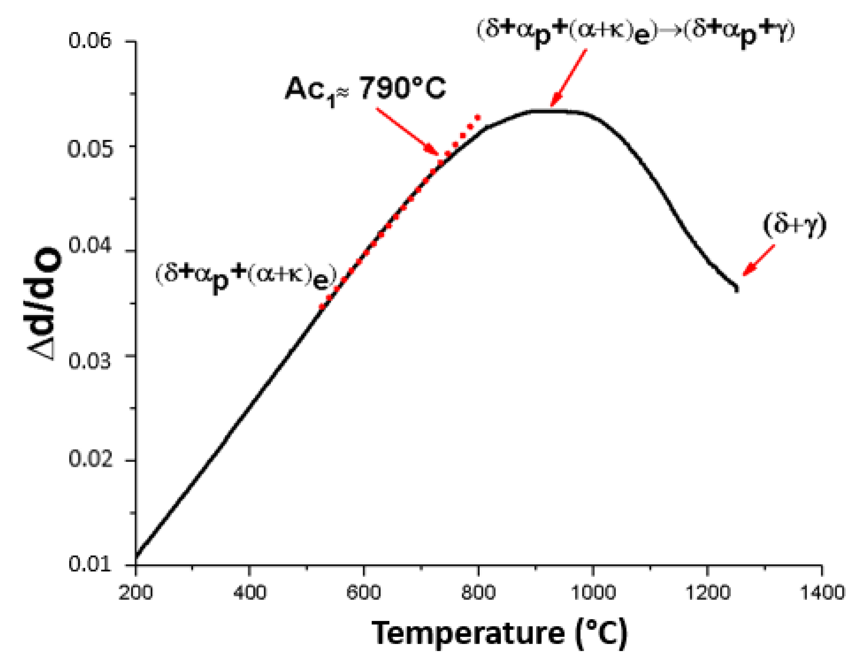
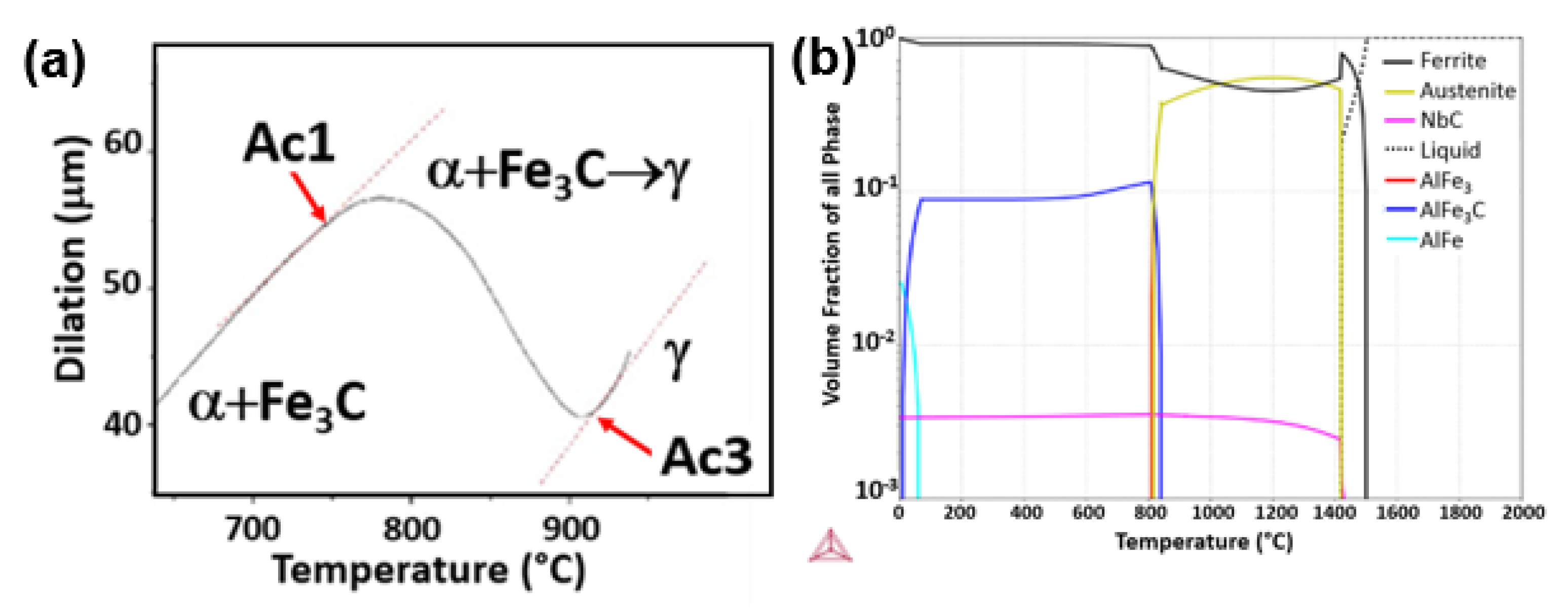
3.1. Dilatometric Curve during Heating

After the dilatometry test, the heating profile was analyzed for all evaluated conditions. A typical dilatometric curve during heating is shown in Figure 1, wherein a first inflection is observed at about 790 °C, indicated by Ac1 as the eutectoid reversal transformation temperature. This reversal transformation needs a temperature range to occur. However, a second inflection was not observed as the heating progressed, which would define the Ac3 temperature as the final temperature of the eutectoid reversion, from which the material becomes a single-phase for ordinary steel.

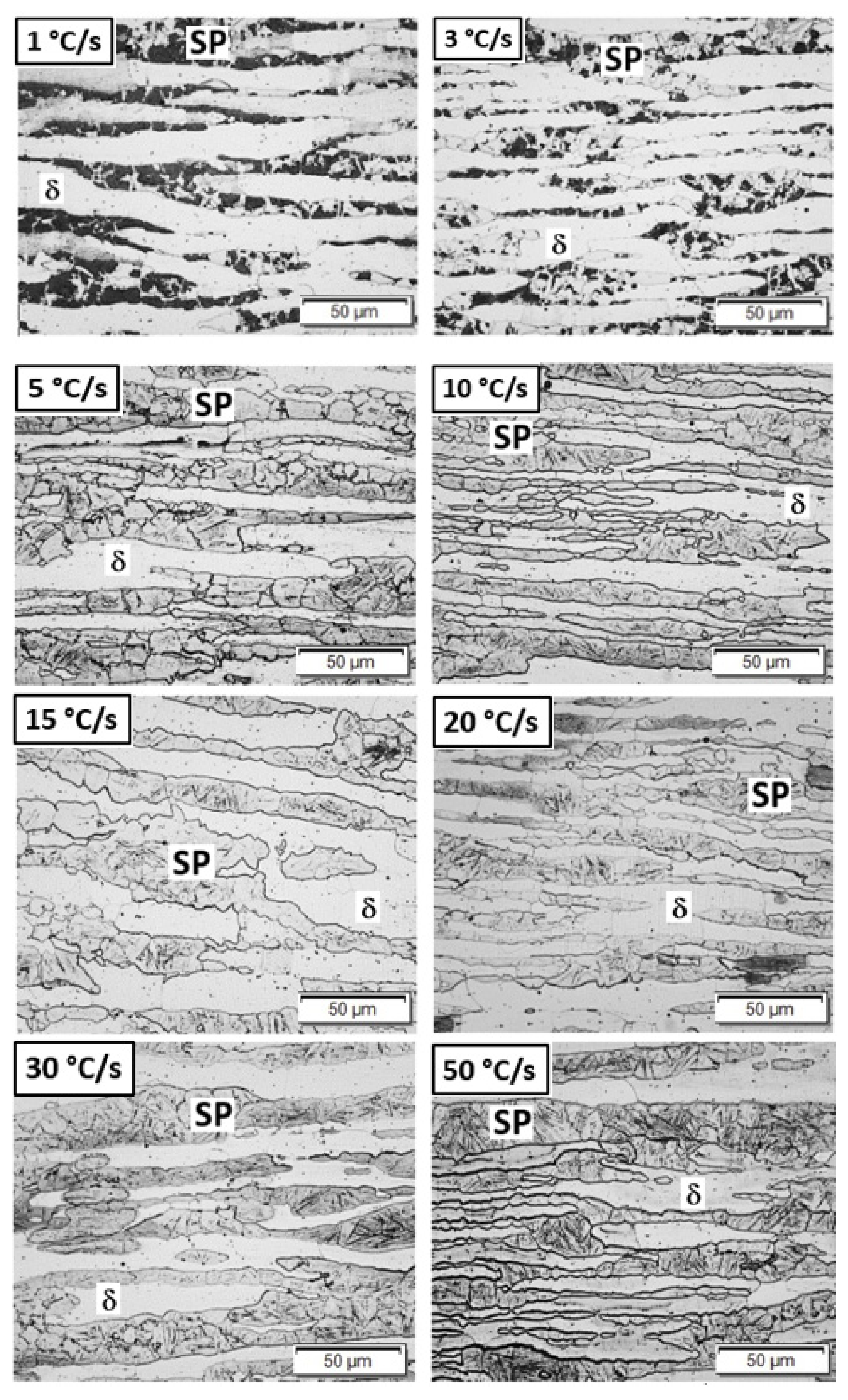
3.2. Microstructural Characterization

Bearing in mind the chemical composition of the new Fe-Mn-Al-C, the analysis started through a characterization via optical microscopy of the evaluated conditions, as shown in Figure 2. The material presented a banded microstructure for all cooling rates. The resulting microstructures have a common brighter matrix in low relief and a second phase (SP) with a distinct morphology. For low cooling rates (1 and 3 °C/s), the second phase is dark, in higher relief, and some regions have a fragmented appearance. At 5 °C/s and higher cooling rates, the second phase assumes a bright lenticular morphology inside the grains. Moreover, the corresponding second-phase microstructures are less fragmented than for lower cooling rates (1 and 3 °C/s).

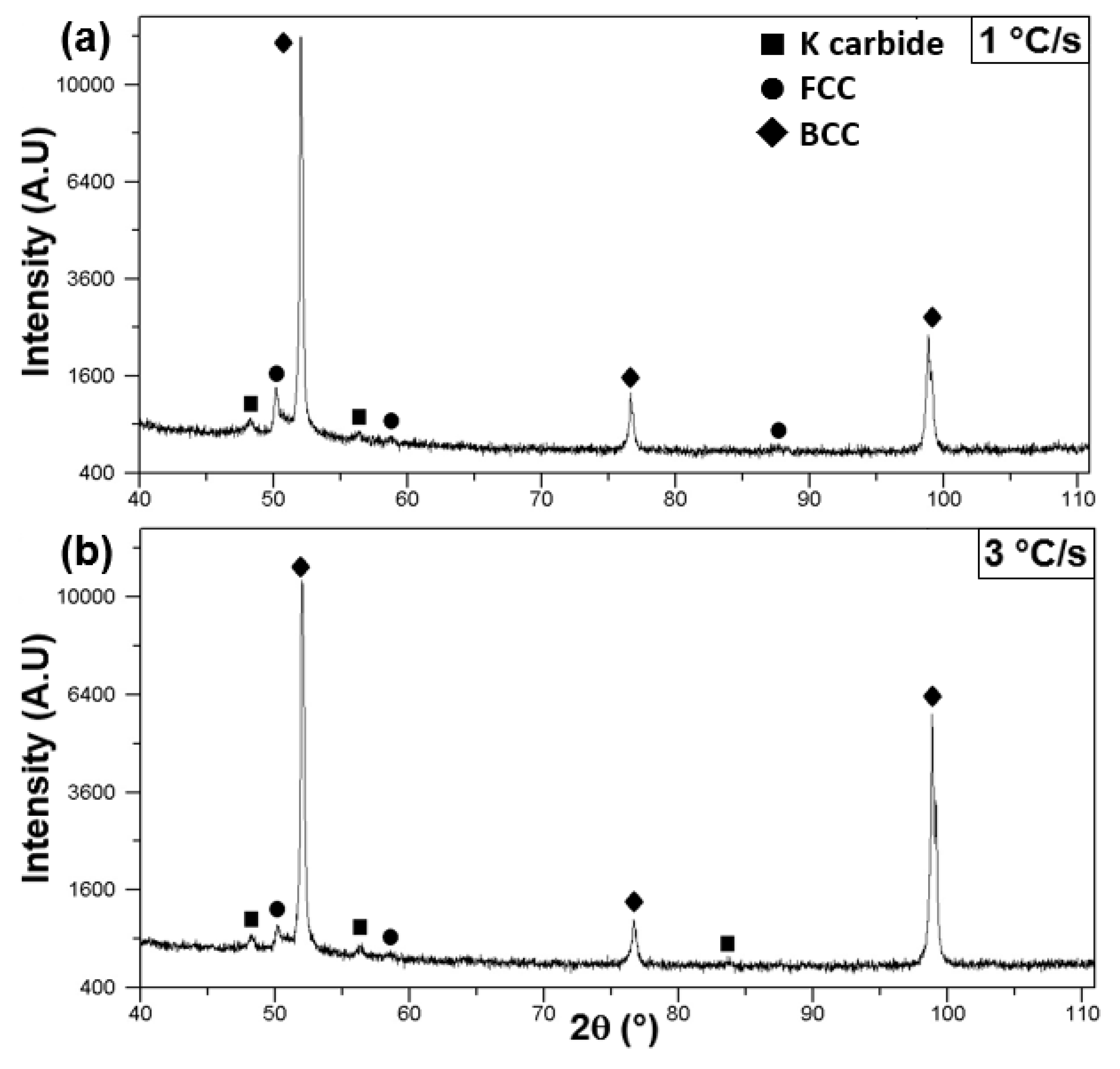
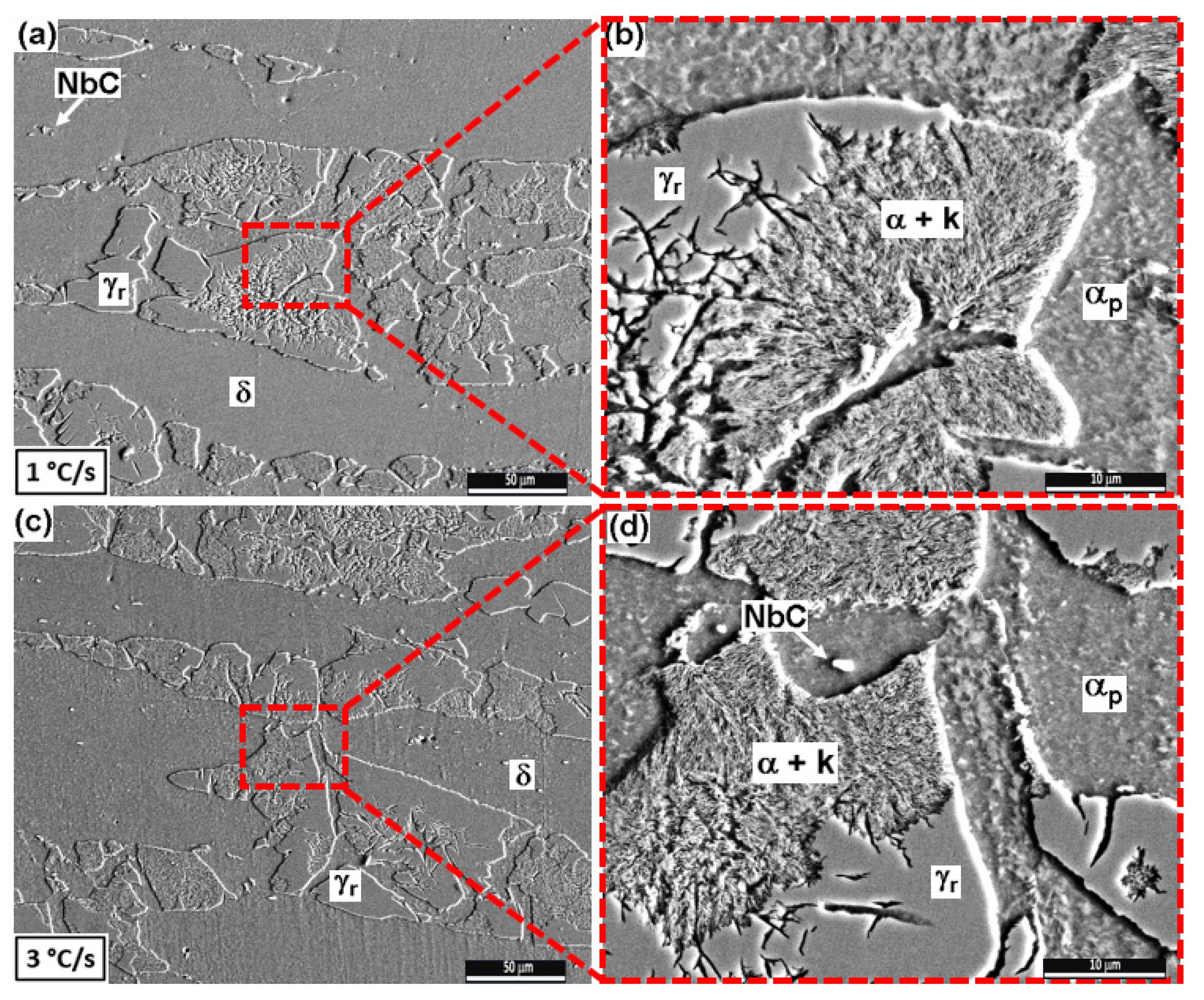
3.2.1. Low Cooling Rates: 1 and 3 °C/s

The diffractograms (Figure 3) obtained for low cooling rates showed diffraction peaks of k-carbide planes (111), (200), and (220) at diffraction angles of 48.2°, 56.3°, and 83.7°, respectively. In addition, they showed diffraction peaks corresponding to (110), (200), and (211) planes of a BCC structure at diffraction angles of 51.9°, 76.6°, and 98.7°, respectively, and diffraction peaks corresponding to the (111), (200), and (211) planes of an FCC structure at diffraction angles of 50.1°, 58.5°, and 87.4°, respectively.
The microstructures observed by SEM/SE for samples with cooling rates of 1 and 3 °C/s are shown in Figure 4. In general, the microstructure of these samples consists of a lower relief matrix (banded), probably due to δ-ferrite, and a second phase associated with a combination of lamellar regions and smooth high relief regions. The second phase comes from austenite decomposition; the lamellar region is α-ferrite (low relief) and k-carbide (high relief). The low-relief areas retained in the middle of the lamellar regions are probably proeutectoid α-ferrite, since these zones were part of austenite grains at higher temperatures, as highlighted in Figure 4. The austenite decomposition was possibly not completed for all cooling rates, due to the evidence of retained austenite (γr).

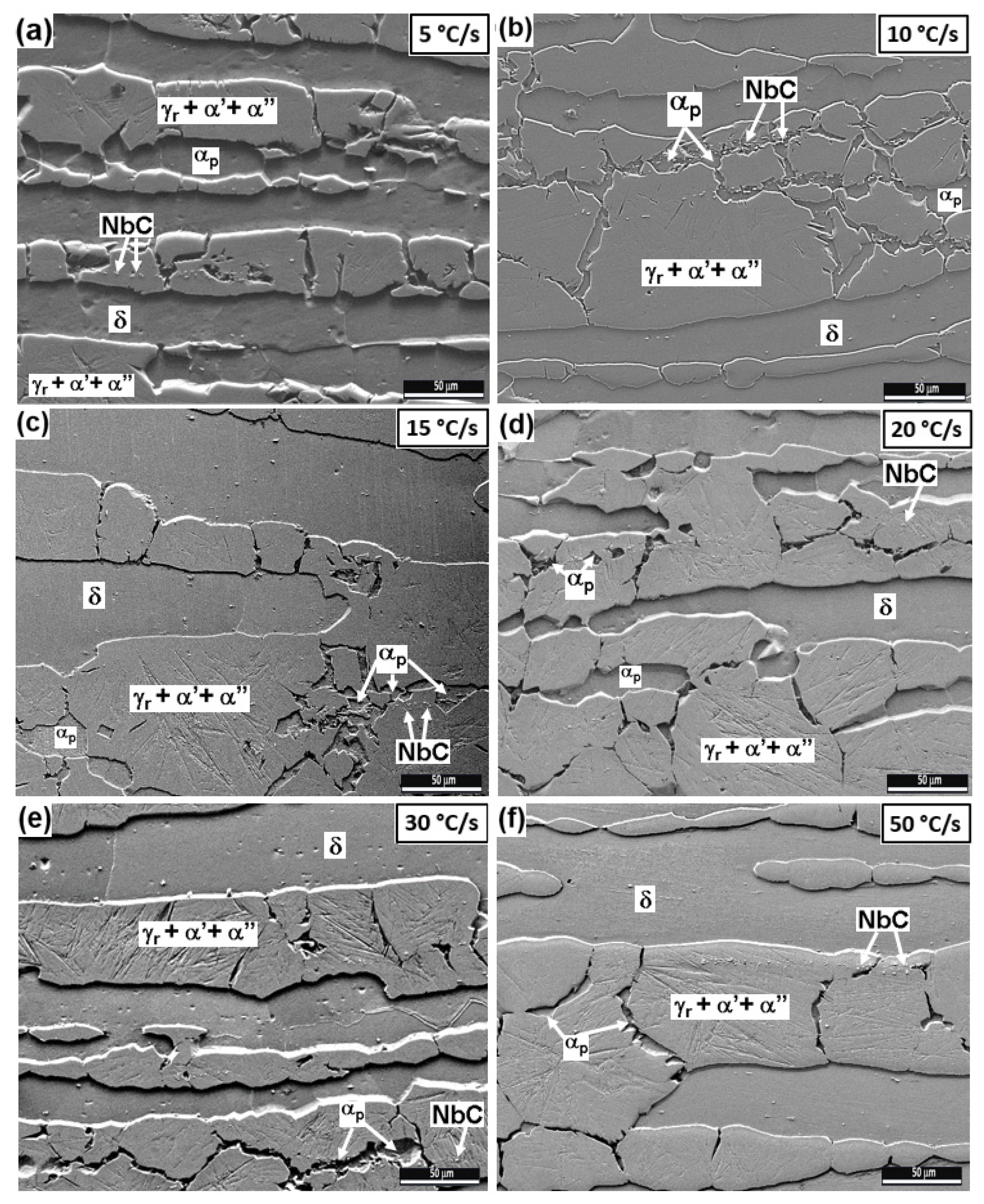
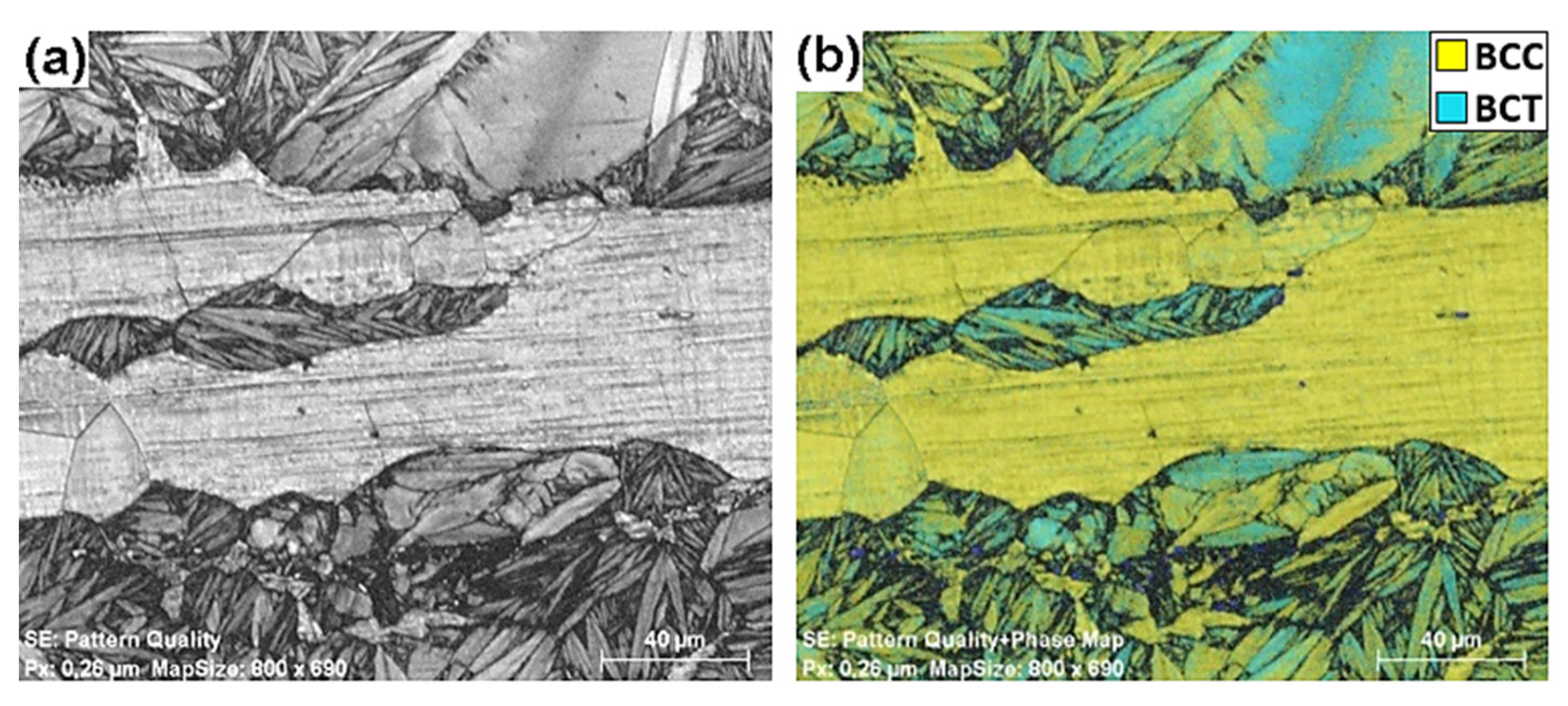
3.2.2. Intermediate and High Cooling Rates: 5 to 50 °C/s

For the test conditions evaluated at continuously cooling rates of 5, 10, 15, 20, 30, and 50 °C/s, the diffractograms showed the same aspect as Figure 5, which was obtained for a cooling rate of 10 °C/s. It is worth observing that the intermediate and high cooling rates suppressed the formation of k-carbide since the diffraction patterns did not show peaks corresponding to this carbide, which was detected at low cooling rates of 1 and 3 °C/s (Figure 3). The diffractograms showed diffraction peaks corresponding to (110), (200), and (211) planes of a BCC structure at diffraction angles of 51.9°, 76.6°, and 98.7°, respectively, and diffraction peaks corresponding to the (111), (200), and (211) planes of an FCC structure at diffraction angles of 50.1°, 58.5°, and 87.4°, respectively.
In the micrographs obtained by optical microscopy (Figure 2), lenticular regions can be observed at intermediated and high cooling rates. These regions are probably martensite due to the conditions applied in the dilatometry testing. However, this phase may present a body-centered cubic (BCC) or body-centered tetragonal (BCT) structure. As the peaks of these structures overlap in the X-ray diffraction analysis, an EBSD/SEM analysis was performed (Figure 6) to ascertain the nature of the phases and their arrangement in the microstructure. The EBSD/SEM was performed on the sample obtained after the dilatometry test for a cooling rate of 50 °C/s. This choice of this cooling rate was based on the expected higher martensite fraction to the detriment of the other phases that could also be present. In this way, the martensite structure might be much more evident allowing a correlation with the X-ray diffraction peaks. In Figure 6a, the pattern quality is presented where the lenticular morphology in the high-temperature austenite grain regions is well-defined within low-relief regions of the matrix (δ-ferrite). In the phase map, shown in Figure 6b, one has the indexing of a BCC phase in yellow with a lattice parameter of approximately 2.889 A ˙ . The crystallographic file of the BCC structure did not index only the δ-ferrite region and the possible proeutectoid α-ferrite as expected. This crystallographic file also indexed significant areas of the lenticular aspect regions, which could be the martensite resulting from the austenite decomposition with a BCC structure (α′). However, the EBSD/SEM analysis was also significantly indexed over the region with lenticular morphology, the body-centered tetragonal (BCT) phase, herein referred to as α″, with lattice parameters of a = b = 2.846 A ˙ and c = 3.053 A ˙ , identified by the cyan color in Figure 6b.
Figure 7 shows the microstructures obtained after the dilatometry tests at cooling rates from 5 to 50 °C/s. For these conditions, a visible banded matrix in lower relief (δ-Ferrite) might be inferred, along with a phase combination linked to the second phase shown in high relief. The second-phase regions present characteristics that explain the grain fragmentation, resulting in a mixture of two high-relief regions, one with a smooth aspect and the other with a lenticular morphology. The martensite can be ascribed to the lenticular areas resulting from a diffusionless transformation from the austenitic field. According to the EBSD/SEM analysis, such lenticular regions might present BCC (α′) and BCT (α″) structures. Due to Nb addition, niobium carbide (NbC) is also observed in the microstructures shown in Figure 7.

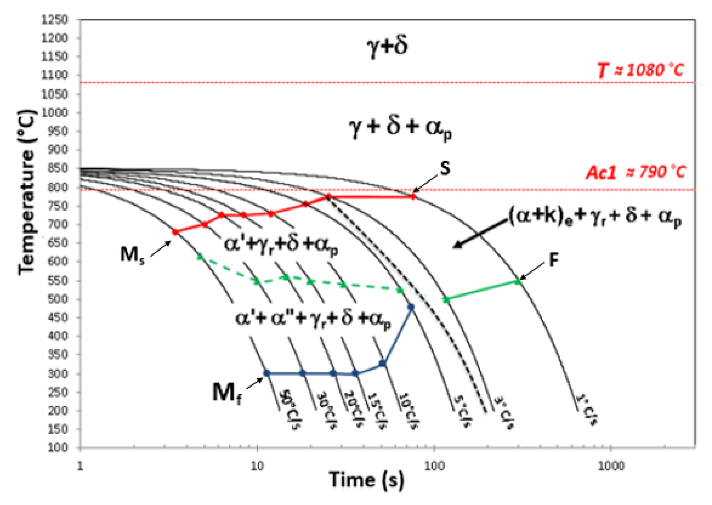
3.3. Continuous Cooling Transformation: CCT Diagram

A detailed investigation of the CCT curves obtained from the dilatometry tests was performed to correlate with the microstructural observations and X-ray results. The corresponding microstructural observations are provided in Figure 4 and Figure 7. These combined analyzes can infer relationships between the inflection points observed in the profiles of the cooling curves evaluated. These inflections arising from the volume variations causing a deviation from the linearity of these cooling curves (Figure 8). As can be seen in the alloy under study, discrete deviations from linearity occurred, which were meticulously evaluated by applying two distinct analysis methods: the tangent method and the derivative method. From these data, it is possible to define the temperatures corresponding to the phase transformations of the Fe-Mn-Al-C alloy. The continuous cooling transformation diagram (CCT) obtained for the alloy is shown in Figure 9. This diagram highlights the Ac1 temperature, approximately 790 °C, determined as the average slope changes during the heating step for all samples, as shown in Figure 1.
From the continuous cooling after the soaking temperature of 1250 °C to 850 °C with a rate of 1 °C/s, it was possible to infer that the Fe-Mn-Al-C alloy has a two-phase field at higher temperatures composed of δ-ferrite and austenite (γ). The δ-ferrite phase is stable in this alloy, and hence, is present during cooling down to room temperature. Moreover, from the characteristics and morphologies observed in the resulting microstructures, it can be inferred that proeutectoid α-ferrite (αp) formation occurs at about 1080 °C.
Conversely, when evaluating the cooling from 850 °C at low cooling rates (1 and 3 °C/s), the austenite decomposes into a lamellar eutectoid microconstituent composed of k-carbide and α-ferrite ((α + k)e) through a diffusional transformation, as highlighted in Figure 8 ((α + k)e + γr + δ + αp). In the region between the cooling rates of 3 and 5 °C/s, a dashed black line was inserted due to the distinction in phase morphology verified mainly by optical microscopy (Figure 2). In this region, a more detailed investigation is needed to better identify and understand at which cooling rate the interface between the transformation from austenite to k-carbide and α-ferrite ((α + k)e) and the transformation to martensite (α′ and α″) occurs.
The cooling rates of 5, 10, 15, 20, 30, and 50 °C/s favored martensite formation, as observed by the microstructure (Figure 7). EBSD/SEM analysis (Figure 6) confirmed that this martensite has BCC (identified by α′) and BCT (identified by α″) structures. It is thus possible to infer that the region between the red line and the dashed green line comprises the BCC martensite formation (α′ + γr + δ + αp). In the region between the dashed green line and the blue line, besides the BCC martensite, there is BCT martensite formation (α′ + α″ + γr + δ + αp) (Figure 8).

4. Discussion

4.1. Dilatometric Curve Profile during Heating

The heating profile of the Fe-Mn-Al-C alloy investigated in the present research (Figure 1) is not the typical behavior found in the literature [21]. Commonly, the steels have a well-defined curve with the Ac1 and Ac3 temperatures based on dilatometry tests, as depicted in Figure 10a. The temperature Ac1 corresponds to the beginning of the eutectoid transformation reversion and austenite formation by carbon enrichment in the ferrite from the decomposition of the microconstituents. Complete decomposition of the second phase occurs with increasing temperature, resulting in a single-phase austenite field above the Ac3 temperature, as highlighted in Figure 10a. On the other hand, the heating curve profile (Figure 1) does not show this second inflection (Ac3), indicating that the alloy does not have a single-phase field, i.e., even at elevated temperatures (above 1200 °C) the two phases still exist. The two-phase field at high temperature comprises δ-ferrite and austenite. This observation agrees with the results obtained by Baêta Júnior [20] in a computer simulation using Thermo-Calc (Figure 10b). In that simulation, the chemical composition promotes a two-phase field between δ-ferrite and austenite at high temperatures. At equilibrium, from about 1040 °C to 1350 °C, one finds the coexistence of the δ-ferrite and austenite phases, with the maximum of the austenite content occurring around 1200 °C (Figure 10b). The high Al content of the alloy may be the main reason for shifting the austenite single-phase field for higher C content. The observed result agrees with the diagram presented by Chen et al. [1] for an alloy with the same Al content. According to Chen et al. [1], Al addition to the Fe-C system has a large effect on the phase fields and phase constituents. The two-phase field region (δ + γ) is expanded and is present between intermediate contents of 0.1 to 0.7 wt.% C. The single-phase field from austenite is shifted to the right as the temperature and the C concentration are increased [1,24,25].

4.2. Microstructural Characterization

In the microstructures shown in Figure 2, the banding of the phases is attributed to rolling passes applied to the material before the present experiments [21,26]. In contrast, the new phase is coarsely distributed. This banded microstructure was also observed in Fe-3 to 4Mn-5.5 to 6.5Al-0.3 to 0.5C and Fe-11Mn-10Al-0.9C hot-rolled alloys [27,28]. Bausch et al. [13], Frommeyer, Brüx [6], and Chen et al. [1] also observed ferrite banding in hot-rolled Fe-Mn-Al-C steels.
Figure 3 and Figure 5 show the diffraction peaks indexed with FCC and BCC structures for all the cooling rates. However, there are differences in the diffraction peaks between samples submitted to low cooling rates (1 and 3 °C/s) and intermediate and high rates (5 to 50 °C/s). For cooling rates of 1 and 3 °C/s (Figure 3), the k-carbide phase typical of the Fe-Mn-Al-C alloys was observed, while, for cooling rates of 5 to 50 °C/s (Figure 5), these peaks are absent. The diffraction peaks for the FCC structure are attributed to the austenitic phase. The BCC structure comprises both δ-ferrite and α-ferrite at all cooling rates. The difference between these ferrite phases (δ and α) is related to the partitioning of the elements present in the alloy and chemical gradients, but the lattice parameters are almost identical and it is hard to determine the contributions of the two phases to the diffraction peaks [1,29].
For intermediate and high cooling rates (Figure 5), the diffraction peaks with a BCC symmetry also have the contribution of martensitic phases with BCC (α′) and the BCT (α″) structures. It is worth mentioning that the diffraction angles for these structures are almost the same for the Co-kα radiation used in the experiments. Other works in the literature have also observed diffraction peaks corresponding to BCC, FCC, and k-carbide structures [1,3,6,24,30,31,32,33,34].
The microstructures shown in Figure 4 and Figure 7 are composed of a low-relief matrix and the second phase in high relief, which differs from the matrix by morphological characteristics that depend on the cooling rate. From observations in the literature and morphological features, the matrix is inferred to be δ-ferrite. It is well-known that δ-ferrite is formed at high temperatures and will be present down to room temperature. Furthermore, its stability is related to the chemical composition of the alloy. The high Al content of the alloy under study is responsible for the high ferritic fraction, since this element stabilizes ferrite and restricts the austenite field [1,2,35]. Jiang and Xie [36] observed in the Fe-0.4C-1.5Mn-4Al (wt.%) alloy, which is classified as low-density steel, that both δ-ferrite and α-ferrite have a higher Al concentration in the banded structure corresponding to δ-ferrite.
It is worth observing that differentiation of the δ and α ferrite phases in these steels, in general, could be achieved by following the evolution of the grains from the solidification to room temperature. In the as-received microstructure resulting from the hot-rolled condition, the δ-ferrite is characterized by large and elongated grains. On the other hand, the α-ferrite phase nucleates from austenite at grain boundaries as a proeutectoid constituent or as part of the microstructure resulting from eutectoid decomposition.
Morphologically, previous austenite can be viewed as large blocks subdivided into coarse grains (high relief) formed between δ-ferrite bands (low relief). However, the previous austenite presents a fragmentation that allows the formation of a low relief area, which, in turn, can be ascribed to proeutectoid α-ferrite (αp). According to the equilibrium diagram (Figure 10b), this phase may exist in the alloy under investigation. The formation of these low relief areas among the previous austenite grains has been observed by Jeong et al. [37] for hot-rolled samples of a Fe-9Mn-6Al-0.15C alloy. The authors conclude that the low-relief regions among martensite and retained austenite are composed of proeutectoid α-ferrite formed before the martensitic transformation onset.
It is likely that the high-relief (smooth) regions depicted in Figure 4 and Figure 7 are composed of retained austenite. The diffractograms of Figure 3 and Figure 5 corroborate that idea. The retained austenite arises from its stability due to the alloying elements of the Fe-Mn-Al-C system [1,11,24,38]. Based on the Thermo-Calc numerical predictions depicted in Figure 10b, the austenite is fully consumed at 800 °C. However, the cooling rates used in the present work were not enough to complete the austenite decomposition. Another potential contribution to the presence of the retained austenite is the grain-size effect upon the final martensitic transformation temperature associated with the BCC and BCT structures. Using in situ X-ray diffraction analyses in a synchrotron accelerator, Jimenez-Melero et al. [39] monitored the martensitic transformation in low-alloyed multiphase steels. They observed that the stability of austenite is controlled by the local C concentration and the grain size. Since coarse grains of previous austenite were observed in the alloy under study, this morphology likely contributed to the stability of the austenite, in addition to the C and Al content that is dissolved in this phase [1,11,24,38].
In the low cooling rate range (1 and 3 °C/s), austenite decomposition resulted in the formation of lamellar colonies, which suggests that the microconstituent is composed of k-carbide lamellae (high relief) interspersed by α-ferrite (low relief) (Figure 4). According to Mapelli et al. [3], there must be enough driving force and reaction speed to trigger austenite decomposition. This effect requires a specific combination of chemical composition, thermal energy input, and thermodynamic stability of the active phase. Low cooling rates (1 and 3 °C/s) favor such conditions, as shown in Figure 4. The correlation of the results obtained on the alloy under study with those available in the literature indicates that the formation of k-carbide in high Al and low Mn (Mn < 10 wt.%), as is the case of the alloy evaluated (Mn = 0.77 wt.%), occurs by eutectoid decomposition (γ = α + k) from the Al partitioning together with the C diffusion in the austenite [3,7,24,27,40]. It is also observed that the precipitation of the lamellar microconstituent (α + k) follows a trend by starting at the austenite grain boundaries and has its growth directed towards the interior of the grains, as also observed by Cheng et al. [41].
For intermediate and high cooling rates (5 to 50 °C/s), the austenite transformed to martensite in the retained austenite regions. Increasing the cooling rate results in the formation of a higher martensite fraction. Moreover, the martensite formation may be influenced by the C and Al contents in the austenite and the evaluated conditions of each cooling rate [7]. Sohn et al. [42] also observed this behavior in hot-rolled samples of Fe-3.5Mn-6Al-0.3C steel subjected to rapid cooling. The EBSD/SEM analysis in Figure 7 shows that this phase can present two crystalline structures: BCC (α′) and BCT (α″). Nevertheless, it is impossible to distinguish these two structures in the micrographs, so the lenticular region was indicated with the presence of α′ + α″ (Figure 7).
The kinetics of martensitic transformation is influenced by the chemical composition and the homogeneity of the alloying element, especially C, in the austenitic grains. In addition, the influence of the cooling rate and the austenite grain size can affect the martensite formation temperature. This martensite with BCT structure is formed when the alloy has high C concentrations, generally above the solubility limit of this element in the BCC structure [39,43,44,45,46]. When confronting the observations cited with the results of the alloy under study, there are indications that martensite formation with BCC (α′) and BCT (α″) structures comes from a compositional heterogeneity in the volume of the austenite grains. The time interval of 300 s at the soaking temperature of 1250 °C was insufficient for the complete homogenization of the alloying elements in the austenite grains, since the alloy has a high content of Al and Nb and a medium C content. According to Da Silva De Souza, Moreira and De Faria [44], and Van Bohemen [46], temperature and soaking time do not directly affect the martensite transformation kinetics. However, the changes produced in soaking, either in the austenite chemical composition (phase precipitation/dissolution) or in the austenite grain size, influence martensite formation and must be considered.
The Nb amount added to the alloy under study, combined with C, promoted the formation of niobium carbide (NbC). The presence of this carbide is most evident in the micrographs of the samples submitted to cooling rates of 5 to 50 °C/s, as shown in Figure 7. According to the equilibrium diagram (Figure 9), NbC precipitation has its onset near the liquidus temperature and is observed throughout the temperature range [20,21]. Other works of the Fe-Mn-Al-C alloy with Nb addition, such as Baligidad [47], Kwon [48], Zargaran [49], and Sozańska-Jędrasik [18], have also mentioned the presence of niobium carbides. Khaple et al. [32], when evaluating a Fe-0.35C-7Al (wt.%) alloy with different Nb concentrations (0.2; 0.4; 0.7 and 1 (wt.%) observed that the increment of this element promoted an increase in the NbC fraction. Khaple et al. [32] also pointed out that there was no Nb presence in the k-carbide.
The Nb addition may have influenced the microstructure of the alloy under study in the following aspects: (i) this element in solid solution may have contributed to the formation of the ferritic matrix formation, since it is considered an alphagenic element [50]; (ii) the NbC precipitation involves carbon consumption, and this may promote a carbon impoverishment in the austenite. Since the k-carbide precipitation requires C and Al to be dissolved in the austenite, this C impoverishment may impair the formation of this carbide [32,51]; (iii) during the thermal cycling of the alloy under study, the decomposition of pre-existing NbC may occur during heating and soaking. This NbC decomposition and/or precipitation favors a local compositional variation, which contributes to the heterogeneity of the alloying elements dissolved in the volume of the austenitic grains and consequently favors the martensite formation with a BCT structure.

4.3. Continuous Cooling Transformation: CCT Diagram

As observed in Figure 9, the continuous cooling transformation diagram under the evaluated conditions shows the complex phase transformations in this alloy. Firstly, the imposed thermal cycle applied with a cooling rate of 1 °C/s from 1250 °C to 850 °C allowed the formation of proeutectoid α-ferrite (αp). Therefore, there is the coexistence of δ-ferrite, proeutectoid α-ferrite (αp), and austenite (γ) before applying the different cooling rates from 850 °C, which justifies the existence of the proeutectoid α-ferrite (αp) even at the high cooling rates [37]. Secondly, at low cooling rates (1 and 3 °C/s), the austenite decomposes, forming the eutectoid microconstituent composed of lamellae of the k-carbide and α-ferrite ((α + k)e) (Figure 3).
The intermediate and high cooling rates (5 to 50 °C/s) excluded diffusion processes. Under these conditions, martensite formation is favored; see the lenticular morphology in Figure 7. From the observed inflections in the curves obtained in the dilatometry test, it can be inferred that the BCC martensite formation (α′) occurs just below the red line (Figure 9). A low C content in the austenite increases the martensite formation temperature Ms. Since BCT martensite (α″) as it has a higher carbon content, its Ms temperature is lower than that of BCC martensite, and it possibly has the beginning of its formation below the dashed green line. The blue line represents the end of the martensitic transformation.
Due to the δ-ferrite and austenite coexistence at high temperatures and the alloying elements present in the alloy under study, the phase transformations that occur during heating and cooling are complex. These phase transformations depend on variables such as partitioning of the alloy elements, soaking time and temperature, grain homogeneity, and processing parameters, among others.
Therefore, the elaboration of the CCT diagram for the alloy was not trivial. The effects of dilation observed in the curves of the dilatometry test were subtle, making it difficult to accurately determine the temperatures at which some phenomena may be occurring. Zhang et al. [51] also described difficulties in interpreting the dilation effect in the dilatometry curves obtained in alloys of Fe-10Mn-xAl-yC (x = 3, 6, 9 and 12 wt.%, and y = 0, 0.2, 0.4, 0.8 and 1.2 wt.%). The authors indicated that the dilation was too small to identify the exact starting temperatures for the alloys studied. They compared simulation data with available experimental data for the alloy and suggested that more experimental information was needed to improve the predictability of the available parameters.

5. Conclusions

The study on phase transformations of a new chemical composition Fe-7.1Al-0.7Mn-0.4C-0.3Nb of the Fe-Mn-Al-C system leads to the following conclusions:
-
All investigated cooling rates applied in the dilatometry tests allowed the formation of a microstructure with proeutectoid α-ferrite, δ-ferrite, NbC, and retained austenite;
-
Cooling rates of 1 and 3 °C/s facilitated the decomposition of eutectoid austenite to form lamellar colonies, while cooling rates equal to or higher than 5 °C/s favored martensite formation with BCC and BCT structures;
-
The addition of Nb may influence the final microstructure of the alloy due to its contribution to stabilization of the ferritic matrix and the formation of niobium carbide;
-
The δ-ferrite and austenite coexistence at high temperatures and the added alloying elements promoted distinct variables that resulted in complex phase transformations observed in the continuous cooling transformation diagram obtained for the alloy under study.

Author Contributions

M.A.M.G.: conceptualization, methodology, formal analysis, investigation, visualization, and writing—original draft preparation; E.d.S.B.J., R.d.S.T., G.O.d.N. and S.S.O.: conceptualization and writing—review and editing; D.N.F.L.: formal analysis, investigation, and methodology; A.d.S.P., L.P.B. and L.P.M.: supervision, validation, writing review, and editing; All authors have read and agreed to the published version of the manuscript.

Funding

The authors also acknowledge the funding agencies for the research productivity scholarships (PQ-2) from CNPq (Process 307798/2015-1), CAPES and CNPq linked to PPGCM/SE8-IME, Senior Qualitec subsidized by UERJ associated to PPG-EM/UERJ, as well as FAPERJ for the APQ-1 Research Project (Process E-26_010-001920_2015). Luciano Pessanha Moreira acknowledges CNPq (Brazil) for the PQ2 research grant 306141/2019-1 and FAPERJ (Rio de Janeiro, Brazil) for the APQ1 research grant E-26/010.001858/2015. Finep (Financiadora de Estudos e Projetos) for the financial support granting the Gleeble 3500 thermomechanical physical simulation system acquisition (MCT/Finep/CT-INFRA-PROINFRA-02/2010, contract number 01.12.0228.03).

Institutional Review Board Statement

Not applicable.

Informed Consent Statement

Not applicable.

Data Availability Statement

Not applicable.

Acknowledgments

The authors would like to thank the following institutions for their support in this research work: Villares Metals—Sumaré/SP for the melting, forging, previous rolling, and chemical analysis via optical emission spectroscopy (OES), and the IME Laboratories. The authors sincerely acknowledge. The authors acknowledge Ronaldo Sérgio de Biasi for his contribution to the English revision of the manuscript.

Conflicts of Interest

The authors declare no conflict of interest.

References

  1. Chen, S.; Rana, R.; Haldar, A.; Ray, R.K. Current State of Fe-Mn-Al-C Low Density Steels. Prog. Mater. Sci. 2017, 89, 345–391. [Google Scholar] [CrossRef]
  2. Zambrano, O.A. A General Perspective of Fe-Mn-Al-C Steels. J. Mater. Sci. 2018, 53, 14003–14062. [Google Scholar] [CrossRef] [Green Version]
  3. Mapelli, C.; Barella, S.; Gruttadauria, A.; Mombelli, D.; Bizzozero, M.; Veys, X. γ Decomposition in Fe-Mn-Al-C Lightweight Steels. J. Mater. Res. Technol. 2020, 9, 4604–4616. [Google Scholar] [CrossRef]
  4. Zhang, M.; Cao, W.; Dong, H.; Zhu, J. Element Partitioning Effect on Microstructure and Mechanical Property of the Micro-Laminated Fe-Mn-Al-C Dual Phase Steel. Mater. Sci. Eng. A 2016, 654, 193–202. [Google Scholar] [CrossRef]
  5. Gutierrez-Urrutia, I.; Raabe, D. High Strength and Ductile Low Density Austenitic FeMnAlC Steels: Simplex and Alloys Strengthened by Nanoscale Ordered Carbides. Mater. Sci. Technol. 2014, 30, 1099–1104. [Google Scholar] [CrossRef] [Green Version]
  6. Frommeyer, G.; Brüx, U. Microstructures and Mechanical Properties of High-Strength Fe-Mn-AI-C Light-Weight TRIPLEX Steels. Steels Automot. Appl. 2006, 77, 627–633. [Google Scholar] [CrossRef]
  7. Kim, H.; Suh, D.W.; Kim, N.J. Fe-Al-Mn-C Lightweight Structural Alloys: A Review on the Microstructures and Mechanical Properties. Sci. Technol. Adv. Mater. 2013, 14, 014205. [Google Scholar] [CrossRef]
  8. Kimura, Y.; Handac, K.; Hayashid, K.; Mishima, Y. Microstructure Control and Ductility Improvement of the Two-Phase γ-Fe/κ-(Fe, Mn)3AlC Alloys in the Fe-Mn-Al-C Quaternary System. Intermetallics 2004, 12, 607–617. [Google Scholar] [CrossRef]
  9. Woo, S.D.; Kim, N.J. Low-Density Steels. Scr. Mater. 2013, 68, 337–338. [Google Scholar] [CrossRef]
  10. Zuazo, I.; Hallstedt, B.; Lindahl, B.; Selleby, M.; Soler, M.; Etienne, A.; Perlade, A.; Hasenpouth, D.; Massardier-Jourdan, V.; Cazottes, S.; et al. Low-Density Steels: Complex Metallurgy for Automotive Applications. JOM 2014, 66, 1747–1758. [Google Scholar] [CrossRef]
  11. Frommeyer, G.; Drewes, E.J.; Engl, B. Physical and Mechanical Properties of Iron-Aluminium-(Mn, Si) Lightweight Steels. Rev. Métall. 2000, 97, 1245–1253. [Google Scholar] [CrossRef]
  12. Suh, D.W.; Park, S.J.; Lee, T.H.; Oh, C.S.; Kim, S.J. Influence of Al on the Microstructural Evolution and Mechanical Behavior of Low-Carbon, Manganese Transformation-Induced-Plasticity Steel. Metall. Mater. Trans. A Phys. Metall. Mater. Sci. 2010, 41, 397–408. [Google Scholar] [CrossRef] [Green Version]
  13. Bausch, M.; Frommeyer, G.; Hofmann, H.; Balichev, E.; Soler, M.; Didier, M.; Samek, L. Ultra High-Strength and Ductile FeMnAlC Light-Weight Steels; The Publications Office of the European Union: Luxembourg, 2013; ISBN 9789279222450. [Google Scholar]
  14. Brüx, U.; Frommeyer, G.; Jimenez, J. Light-Weight Steels Based on Iron-Aluminium—Influence of Micro Alloying Elements (B, Ti, Nb) on Microstructures, Textures and Mechanical Properties. Mater. Technol. Steel Res. 2002, 73, 543–548. [Google Scholar] [CrossRef]
  15. Zheng, W.; He, S.; Selleby, M.; He, Y.; Li, L.; Lu, X.G.; Ågren, J. Thermodynamic Assessment of the Al-C-Fe System. Calphad Comput. Coupling Phase Diagr. Thermochem. 2017, 58, 34–49. [Google Scholar] [CrossRef]
  16. Chen, P.; Li, X.; Yi, H. The κ -Carbides in Low-Density Fe-Mn-Al-C Steels: A Review on Their Structure, Precipitation and Deformation Mechanism. Metals 2020, 10, 1021. [Google Scholar] [CrossRef]
  17. Wang, C.J.; Chang, Y.C. TEM Study of the Internal Oxidation of an Fe-Mn-Al-C Alloy after Hot Corrosion. Oxid. Met. 2002, 57, 363–378. [Google Scholar] [CrossRef]
  18. Sozańska-Jędrasik, L.; Mazurkiewicz, J.; Matus, K.; Borek, W. Structure of Fe-Mn-Al-C Steels after Gleeble Simulations and Hot-Rolling. Materials 2020, 13, 739. [Google Scholar] [CrossRef] [Green Version]
  19. Lu, W.J.; Zhang, X.F.; Qin, R.S. Structure and Properties of κ -Carbides in Duplex Lightweight Steels. Ironmak. Steelmak. Process. Prod. Appl. 2016, 42, 626–631. [Google Scholar] [CrossRef] [Green Version]
  20. De Souza Baêta Júnior, E. Análise Temodinâmica e Cristalográfica Aplicada Na Produção de Aço Leve Ligado Com Al e Nb Contendo Ferrita Delta, Instituto Militar de Engenharia—IME, 2020. Available online: http://aquarius.ime.eb.br/~debiasi/tese%20Eustaquio.pdf (accessed on 14 June 2022).
  21. Gurgel, M.A.M. Comportamento Mecânico a Quente de Um Aço Do Sistema Fe-Mn-Al-C Com Adição de Nióbio, Instituto Militar de Engenharia—IME, 2021. Available online: http://aquarius.ime.eb.br/~debiasi/Tese%20Monica%20Magalhaes.pdf (accessed on 14 June 2022).
  22. Dynamic Systems Inc. Gleeble Operations Manual; Dynamic Systems Inc.: Poughkeepsie, NY, USA, 2014. [Google Scholar]
  23. ASTM-E3-11; Standard Guide for Preparation of Metallographic Specimens. ASTM: West Conshohocken, PA, USA, 2017; Volume 03.01, pp. 1–12.
  24. Rana, R.; Lahaye, C.; Ray, R.K. Overview of Lightweight Ferrous Materials: Strategies and Promises. JOM 2014, 66, 1734–1746. [Google Scholar] [CrossRef] [Green Version]
  25. Krizan, D.; Steineder, K.; Kaar, S.; Hebesberger, T. Development of Third Generation Advanced High Strength Steels for Automotive Applications. In Proceedings of the 18th International Scientific Conference, Rajecke Teplice, Slovakia, 10–11 October 2018; pp. 1–15. [Google Scholar]
  26. Gurgel, M.A.M.; Baêta Júnior, E.d.S.; da silva Teixeira, R.; Moreira, L.P.; Brandao, L.P.; Paula, A.d.S. Caracterização Microestrutural de Uma Liga Fe-7,1Al-0,7Mn-0,4C-0,3Nb Do Sistema Fe-Mn-Al-C. Rev. Matér. 2022, 27, 1–10. [Google Scholar] [CrossRef]
  27. Shin, S.Y.; Lee, H.; Han, S.Y.; Seo, C.H.; Choi, K.; Lee, S.; Kim, N.J.; Kwak, J.H.; Chin, K.G. Correlation of Microstructure and Cracking Phenomenon Occurring during Hot Rolling of Lightweight Steel Plates. Metall. Mater. Trans. A Phys. Metall. Mater. Sci. 2010, 41, 138–148. [Google Scholar] [CrossRef] [Green Version]
  28. Liu, D.; Ding, H.; Cai, M.; Han, D. Hot Deformation Behavior and Processing Map of a Fe-11Mn-10Al-0.9C Duplex Low-Density Steel Susceptible to κ-Carbides. J. Mater. Eng. Perform. 2019, 28, 5116–5126. [Google Scholar] [CrossRef]
  29. Han, S.Y.; Shin, S.Y.; Lee, H.J.; Lee, B.J.; Lee, S.; Kim, N.J.; Kwak, J.H. Effects of Annealing Temperature on Microstructure and Tensile Properties in Ferritic Lightweight Steels. Metall. Mater. Trans. A Phys. Metall. Mater. Sci. 2011, 43, 843–853. [Google Scholar] [CrossRef] [Green Version]
  30. Kaar, S.; Krizan, D.; Schwabe, J.; Hofmann, H.; Hebesberger, T.; Commenda, C.; Samek, L. Influence of the Al and Mn Content on the Structure-Property Relationship in Density Reduced TRIP-Assisted Sheet Steels. Mater. Sci. Eng. A 2018, 735, 475–486. [Google Scholar] [CrossRef]
  31. Khaple, S.; Prakash, U.; Golla, B.R.; Satya Prasad, V.V. Effect of Niobium Addition on Microstructure and Mechanical Properties of Fe–7Al–0.35C Low-Density Steel. Metallogr. Microstruct. Anal. 2020, 9, 127–139. [Google Scholar] [CrossRef]
  32. Sinha, M.; Ahad, S.; Chaudhry, A.K.; Ghosh, S. Kinetic Constraints of δ-Ferrite to the Formation of Kappa (κ) Carbide in a Fe-4Mn-9Al-0.3C Wt Pct Low-Density Steel. Metall. Mater. Trans. A Phys. Metall. Mater. Sci. 2020, 51, 809–817. [Google Scholar] [CrossRef]
  33. Zhou, N.; Song, R.; Yang, F.; Li, X.; Li, J. Influence of Annealing Temperature on Microstructure and Three-Stage Strain Hardening Behavior in Cold-Rolled Fe-Mn-Al-C Steel. JOM 2019, 71, 4105–4113. [Google Scholar] [CrossRef]
  34. Choi, Y.; Suh, D.W.; Bhadeshia, H.K.D.H. Retention of δ-Ferrite in Aluminium-Alloyed TRIP-Assisted Steels. Proc. R. Soc. A Math. Phys. Eng. Sci. 2012, 468, 2904–2914. [Google Scholar] [CrossRef]
  35. Jiang, Y.; Xie, C. Research and Development of 780MPa Grade Low-Density Steels. IOP Conf. Ser. Mater. Sci. Eng. 2019, 493, 012120. [Google Scholar] [CrossRef]
  36. Jeong, J.; Lee, C.Y.; Park, I.J.; Lee, Y.K. Isothermal Precipitation Behavior of J-Carbide in the Fe-9Mn-6Al-0.15C Lightweight Steel with a Multiphase Microstructure. J. Alloys Compd. 2013, 574, 299–304. [Google Scholar] [CrossRef]
  37. Sozańska-Jędrasik, L.; Mazurkiewicz, J.; Borek, W.; Matus, K. Carbides Analysis of the High Strength and Low Density Fe-Mn-Al-Si Steels. Arch. Metall. Mater. 2018, 63, 265–276. [Google Scholar] [CrossRef]
  38. Jimenez-Melero, E.; van Dijk, N.H.; Zhao, L.; Sietsma, J.; Offerman, S.E.; Wright, J.P.; van der Zwaag, S. Martensitic Transformation of Individual Grains in Low-Alloyed TRIP Steels. Scr. Mater. 2007, 56, 421–424. [Google Scholar] [CrossRef]
  39. Seol, J.B.; Raabe, D.; Choi, P.; Park, H.S.; Kwak, J.H.; Park, C.G. Direct Evidence for the Formation of Ordered Carbides in a Ferrite-Based Low-Density Fe-Mn-Al-C Alloy Studied by Transmission Electron Microscopy and Atom Probe Tomography. Scr. Mater. 2013, 68, 348–353. [Google Scholar] [CrossRef]
  40. Cheng, W.C.; Song, Y.S.; Lin, Y.S.; Chen, K.F.; Pistorius, P.C. On the Eutectoid Reaction in a Quaternary Fe-C-Mn-Al Alloy: Austenite → Ferrite + Kappa-Carbide + M23C6 Carbide. Metall. Mater. Trans. A Phys. Metall. Mater. Sci. 2014, 45, 1199–1216. [Google Scholar] [CrossRef]
  41. Sohn, S.S.; Lee, S.; Lee, B.J.; Kwak, J.H. Microstructural Developments and Tensile Properties of Lean Fe-Mn-Al-C Lightweight Steels. JOM 2014, 66, 1857–1867. [Google Scholar] [CrossRef]
  42. Porter, D.A.; Easterling, K.E. Phase Transformation in Metals and Alloys, 3rd ed.; Routledge: London, UK, 1992; ISBN 9788578110796. [Google Scholar]
  43. Da Silva De Souza, S.; Moreira, P.S.; De Faria, G.L. Austenitizing Temperature and Cooling Rate Effects on the Martensitic Transformation in a Microalloyed-Steel. Mater. Res. 2020, 23, 1–9. [Google Scholar] [CrossRef]
  44. Gao, Q.; Wang, C.; Qu, F.; Wang, Y.; Qiao, Z. Martensite Transformation Kinetics in 9Cr-1.7W-0.4Mo-Co Ferritic Steel. J. Alloys Compd. 2014, 610, 322–330. [Google Scholar] [CrossRef]
  45. Van Bohemen, S.M.C.; Sietsma, J. Kinetics of Martensite Formation in Plain Carbon Steels: Critical Assessment of Possible Influence of Austenite Grain Boundaries and Autocatalysis. Mater. Sci. Technol. 2014, 30, 1024–1033. [Google Scholar] [CrossRef]
  46. Baligidad, R.G. Effect of Niobium on Microstructure and Mechanical Properties of High Carbon Fe–10.5 Wt.% Al Alloys. Mater. Sci. Eng. A 2004, 368, 131–138. [Google Scholar] [CrossRef]
  47. Kwon, M.H.; Kim, J.K.; Bian, J.; Mohrbacher, H.; Song, T.; Kim, S.K.; De Cooman, B.C. Solidification Microsegregation and Hot Ductility of Fe-Mn-C-Al-XNb TWIP Steels. Metall. Mater. Trans. A Phys. Metall. Mater. Sci. 2018, 49, 5509–5523. [Google Scholar] [CrossRef]
  48. Zargaran, A.; Kim, H.S.; Kwak, J.H.; Kim, N.J. Effects of Nb and C Additions on the Microstructure and Tensile Properties of Lightweight Ferritic Fe-8Al-5Mn Alloy. Scr. Mater. 2014, 89, 37–40. [Google Scholar] [CrossRef]
  49. Bhadeshia, H.; Honeycombe, R. Steels: Microstructure and Properties, 3rd ed.; Elsevier Ltd.: Amsterdam, The Netherlands, 2017; Volume 48, ISBN 9780750680844. [Google Scholar]
  50. Baêta Júnior, E.d.S.; Botelho, R.A.; Araújo, L.S.; Brandão, L.P.M.; Monteiro, S.N. Microstructure Optimization in δ-Trip Steels with Al and Nb. Mater. Sci. Forum 2018, 930, 501–506. [Google Scholar] [CrossRef]
  51. Zhang, R.; Zheng, W.; Veys, X.; Huyberechts, G.; Springer, H.; Selleby, M. Prediction of Martensite Start Temperature for Lightweight Fe-Mn-Al-C Steels. J. Phase Equilibria Diffus. 2018, 39, 476–489. [Google Scholar] [CrossRef] [Green Version]
Figure 1. Dilatometric curve of the investigated Fe-Mn-Al-C alloy highlighting the phases present in each region (δ = δ-ferrite; αp = proeutectoid ferrite; (α + k)e = eutetoid microconstituent; γ = austenite; k = k-carbide).
Metals 12 01305 g001
Figure 2. Optical microstructures resulting from the dilatometry tests under different continuous cooling rates (δ = Ferritic matrix, SP = Second Phase).
Metals 12 01305 g002
Figure 3. Diffractograms for the dilatometry samples submitted to low cooling rates: (a) 1 °C/s and (b) 3 °C/s (radiation: Co kα).
Metals 12 01305 g003
Figure 4. Micrographs (SEM/SE) of samples tested at low cooling rates of 1 °C/s (a,b) and 3 °C/s: (c,d) (γr = retained austenite; δ = δ-ferrite; α = α-ferrite; αp = proeutectoid α-ferrite; k = k-carbide; NbC = niobium carbide).
Metals 12 01305 g004
Figure 5. Diffractogram obtained from the dilatometry sample tested at a 10 °C/s cooling rate (radiation: Co kα).
Metals 12 01305 g005
Figure 6. EBSD/SEM sample analysis obtained from the dilatometry test under 50 °C/s cooling rate: (a) pattern quality; (b) phase map (BCC = body-centered cubic; BCT = body-centered tetragonal).
Metals 12 01305 g006
Figure 7. Micrographs (SEM/SE) of the samples obtained after dilatometry tests at cooling rates of: (a) 5 °C/s; (b) 10 °C/s; (c) 15 °C/s; (d) 20 °C/s; (e) 30 °C/s; (f) 50 °C/s (γr = retained austenite; δ = δ-ferrite; α = α-ferrite; αp = proeutectoid α-ferrite; α′ = BCC martensite; α″ = BCT martensite; NbC = niobium carbide).
Metals 12 01305 g007
Figure 8. Cooling curves for all samples analyzed in the dilatometry test.
Metals 12 01305 g008
Figure 9. Continuous cooling transformation diagram (CCT) obtained for the Fe-Mn-Al-C alloy, highlighting the phases present in each region (γr = retained austenite; δ = δ-ferrite; α = α-ferrite; αp = proeutectoid α-ferrite; k = k-carbide; (α + k)e = eutectoid microconstituent; α′ = BCC martensite; α″ = BCT martensite; S = eutectoid decomposition start temperature (α + k)e; F = eutectoid decomposition finish temperature; Ms = martensitic transformation start temperature; Mf = martensitic transformation finish temperature).
Metals 12 01305 g009
Figure 10. (a) Dilatometric profile on heating of classical steels, showing a single-phase field at high temperatures [21]; (b) diagram of the volume fractions at equilibrium calculated for the Fe-Mn-Al-C alloy using the Thermo-Calc software [20].
Metals 12 01305 g010
Publisher’s Note: MDPI stays neutral with regard to jurisdictional claims in published maps and institutional affiliations.

