Article

Theoretical Analysis of Grinding Wheel Deflection Angle on Peripheral Grinding Parameters and Grinding Force

1
Postdoctoral Scientific Research Working Station of China Railway Wuhan Bureau Group Co., Ltd., Wuhan 430061, China
2
Postdoctoral Research Station of Transportation Engineering, Wuhan University of Technology, Wuhan 430070, China
3
Gemac Engineering Machinery Co., Ltd., Xiangyang 441000, China
4
School of Mechanical and Electronic Engineering, Wuhan University of Technology, Wuhan 430070, China
*
Author to whom correspondence should be addressed.
Metals 2022, 12(7), 1209; https://doi.org/10.3390/met12071209
Submission received: 17 June 2022 / Revised: 10 July 2022 / Accepted: 15 July 2022 / Published: 17 July 2022
(This article belongs to the Special Issue Advances in Machining Processes of Metallic Materials)

Abstract

:
The peripheral surface of the grinding wheel can grind the rail according to the envelope of the contour of the rail surface, thus a fuller and smoother rail surface can be obtained. Specifically, a better grinding effect can be obtained in that the end face of the grinding wheel deviates from the longitudinal section of the rail at a certain angle. Based on the traditional grinding technology theory, the mathematical models of the peripheral grinding parameters (kinematic contact arc length, wheel-rail grinding contact area, and maximum undeformed chip thickness) and the grinding force are established, in which the angle exists between the grinding wheel end face and the rail longitudinal section. The main influence of grinding wheel circumferential speed, grinding wheel kinematic speed, and the deflection angle of the grinding wheel end face on the grinding parameters and the force are analyzed. The result shows that: when there is angle θ in the models, the ratios of peripheral grinding parameters between up-grinding and down-grinding varies monotonically with the increase in vm, and their maximum variation range is about 12%, vs has the greatest influence on the peripheral grinding parameters, and the maximum variation range of the ratios is about 20% when the vs is 10 m/s. With the increase in the grinding width, Fa’ cannot be ignored and will increase gradually with the increase in angle θ. The analysis and conclusion have guiding significance for the structural design, grinding control strategy, and experimental research regarding rail curved surface grinding equipment.

1. Introduction

During service, the rail will be impacted by the vertical, horizontal, and longitudinal loads of the wheels, which will cause damage, cracks, and breaks at different parts of the rail head and inside the rail, as shown in Figure 1 [1,2]. If these injuries are not dealt with and effectively controlled in time, they will affect and limit the rail service performance and shorten its service life, which will bring high maintenance costs [3]. Grinding is an effective means to prevent and repair rail damage, which is mainly divided into three types: pre-grinding, preventive grinding, and repair grinding [4]. Figure 2 shows the service life of rail injuries regarding unground, reparative, and preventive grinding [5].
It can be seen from Figure 2 that, compared with the unground state, the service life of the rail can be significantly prolonged by reparative grinding, while the service life of the rail can be maximally prolonged by preventive grinding, using the concept of “small grinding amount in a single time, multiple grinding times, and nip in the bud.” This is also a rail grinding method often used at home and abroad [5]. Moreover, scholars from various countries have carried out numerous theoretical and experimental studies on rail grinding technology.
Wang et al. [6] built a physical model of rail surface topography and developed a numerical calculation approach for determining the local roughness. The total percentage error of less than 10% demonstrated the validity of the proposed roughness creation approach. Based on the surface topographies of real grinding wheels, Ding et al. [7] constructed 3D models of grinding wheels and explored the influences of grinding parameters on the grinding forces by means of the simulation of rail grinding processes. The error between the simulation and experimental results was reduced from 10.22 to 4.42% by using a correction factor ks based on the least square method. Reasonable grinding parameters are a significant problem affecting the surface quality of rail grinding. Zhang et al. [8] discussed the surface integrity of grinded rails and the material removal mechanism, analyzing the effect of the abrasive grit size on the residual stress, surface topography, oxidation, and crystal structure of grinded rail surfaces. Gu et al. [9] developed a rail grinding friction testing apparatus and investigated the effects of the rotational speed of the grinding stone on the removal behavior of the rail material. Ding et al. [10] analyzed the grinding chips of the rail grinding from the field and the laboratory in terms of their morphologies, microstructural evolution, and chemical characteristics. By using an inserted semi-artificial thermocouple method, Lin et al. [11] explored the effect of grinding parameters on rail grinding temperature and burn behaviors, proposing the relationship of the surface state, grinding burn, and grinding temperature of the rail specimen. Zhou et al. [12] focused on the removal behaviors of rail material during grinding at different forward speeds, which provided a better understanding for improving grinding efficiency and quality. The grinding process is the most efficient at the forward speed of 3 km/h, and the forward speed should be higher than 4 km/h in the field. Liu et al. [13] investigated the effects of machining parameters on the surface roughness, subsurface microhardness, plastic deformation, and surface morphology, respectively. The experimental results revealed that the thickness of the subsurface plastic deformation layer and the degree of plastic flow increase with the increase in grinding depth, and the thickness of the subsurface plastic deformation layer ranges from 7 μm to 14 μm with the change of grinding depth. Uhlmann et al. [14] tested industrial rail grinding processes under laboratory conditions, with a variation of wheel peripheral speed and depth of cut, evaluated with regard to the achieved surface roughness as well as micro-hardening. Zhang et al. [15] established a three-dimensional finite element model of rail grinding and explored the effects of grinding passes and grinding direction on the material removal behavior of grinding rails during the grinding process. Liu et al. [16] investigated the wear and damage characteristics of the machined wheel/rail materials under dry sliding conditions by virtue of a block-on-ring tribometer. The surface damage morphologies between the rail blocks and the wheel rings after sliding are different; the surface damage of rail blocks is more serious. The worn surface morphology of the wheel rings primarily presents peeling, adhesive wear, and fatigue cracks, while the worn surface morphology exhibits the combination of spalling, furrow wear, peeling, fatigue cracks, and various degrees of adhesion. Liu et al. [17] investigated the influence of grinding pressure on the removal behaviors of rail material in passive grinding by using a self-designed passive grinding simulator. Pereverzev et al. [18] developed a mathematical model for the grinding force in cylindrical plunge grinding, and the grinding conditions, size of the flank wear land areas formed on the grinding wheel cutting grains, properties of the work material, and the geometrical parameters of the grinding tool and work surface are considered. Because process parameters, such as workpiece speed, depth of cut, cutting speed, and minimum quantity lubrication (MQL) [19] flow rate, have a direct influence on the workpiece in the grinding process, and the effect of these process parameters varies from material to material, Khan et al. [20] investigated the effects of the cutting parameter and the cooling mode on the grinding zone temperature, normal forces, and ground surface quality of AISI D2 steel, and analyzed the main influence of process parameter on three different responses based on the developed mathematical model.
As shown in Figure 3, three kinds of small-sized rail grinding machines are commonly used in rail grinding work in permanent way depots of various railway administrations in China. These machines mainly carry out preventive grinding and repairing grinding for the restricted areas of rail grinding, blind areas of large-sized grinding machines, improper grinding of large-sized machines, and periodic spot damage of the rail lines. In the process of rail grinding, operators will push the grinding machine back and forth on the rail, grinding at the rail defect location. Traditional end grinding must gradually adjust the grinding angle according to the rail profile, and there are often many planes and ridges on the surface of the ground rail [21].
Because the grinding wheel wear leads to a concaved arc surface in the peripheral surface of the grinding wheel that matches to the contour of the rail surface, the overall or sectional rail profiling grinding could be realized. By arranging grinding wheels (3 to 5) at different angles on the rail head, the rail profile can be completely enveloped, so as to eliminate damage and execute profile grinding, and to ensure the continuous curve characteristics of the rail profile section after grinding. Compared with grinding at the grinding wheel end face, the advantage of peripheral surface grinding lies in the relative relationship between the grinding wheel and the rail curved surface. On the premise of not affecting the grinding quality at all, it avoids occupying large cross-sectional space, including the interference with the switch point area and frog area, and is especially suitable for the grinding operation requirements of switches, grade crossing, and lines with complex structures. In order to ensure a good grinding effect, the end face of the grinding wheel will be deflected from the longitudinal plane of the rail by a certain angle (generally between 5 and 15), so that the wheel has a better joint state and thermal performance with the rail. Moreover, the abrasive grains of the grinding wheel can be ground to different parts of the rail (tread, gauge angle, and working edge), so that the grinding wheel wears more evenly, prolonging its service life. Wang et al. [22] analyzed the comparative cases at two typical grinding positions with different attitudes, and investigated the effects of applying axis deflection on contact behavior. Zhou et al. [23] presented a numerical model of the grinding force during rail grinding and analyzed the influence of the swing angle of the grinding stone on the grinding area. Wu et al. [24] considered the relationship between the grinding force and the grinding process and proposed a universal method of grinding force modeling in arbitrary 2D freeform grinding, which is based on the infinitesimal approach. The resultant grinding force overall free-form surface along a specific direction can be gained by summing the tangential normal grinding forces on each inclined flat surface.
At present, there is little research on the grinding parameters and grinding force with a deflection angle between the end face of the grinding wheel and the longitudinal section of the rail, and there are no relevant theoretical research results. Miao et al. [25] have provided only exploratory research on this subject. Under the condition that there is a deflection angle between the end face of the grinding wheel and the longitudinal section of the rail, based on the traditional grinding technology theory, the mathematical models of the kinematic contact arc length between the grinding wheel and the rail, the grinding contact area, the maximum undeformed chip thickness of abrasive grains, and the grinding force per unit width of the grinding wheel are theoretically studied, and the main influence of grinding wheel circumferential speed, grinding wheel kinematic speed, and the deflection angle of the grinding wheel end face on the grinding parameters and grinding force are analyzed in Section 2, Section 3, Section 4 and Section 5 of this paper. The above theoretical research provides guiding significance for the structural design, grinding control strategy, and experimental research of rail curved surface grinding machines.

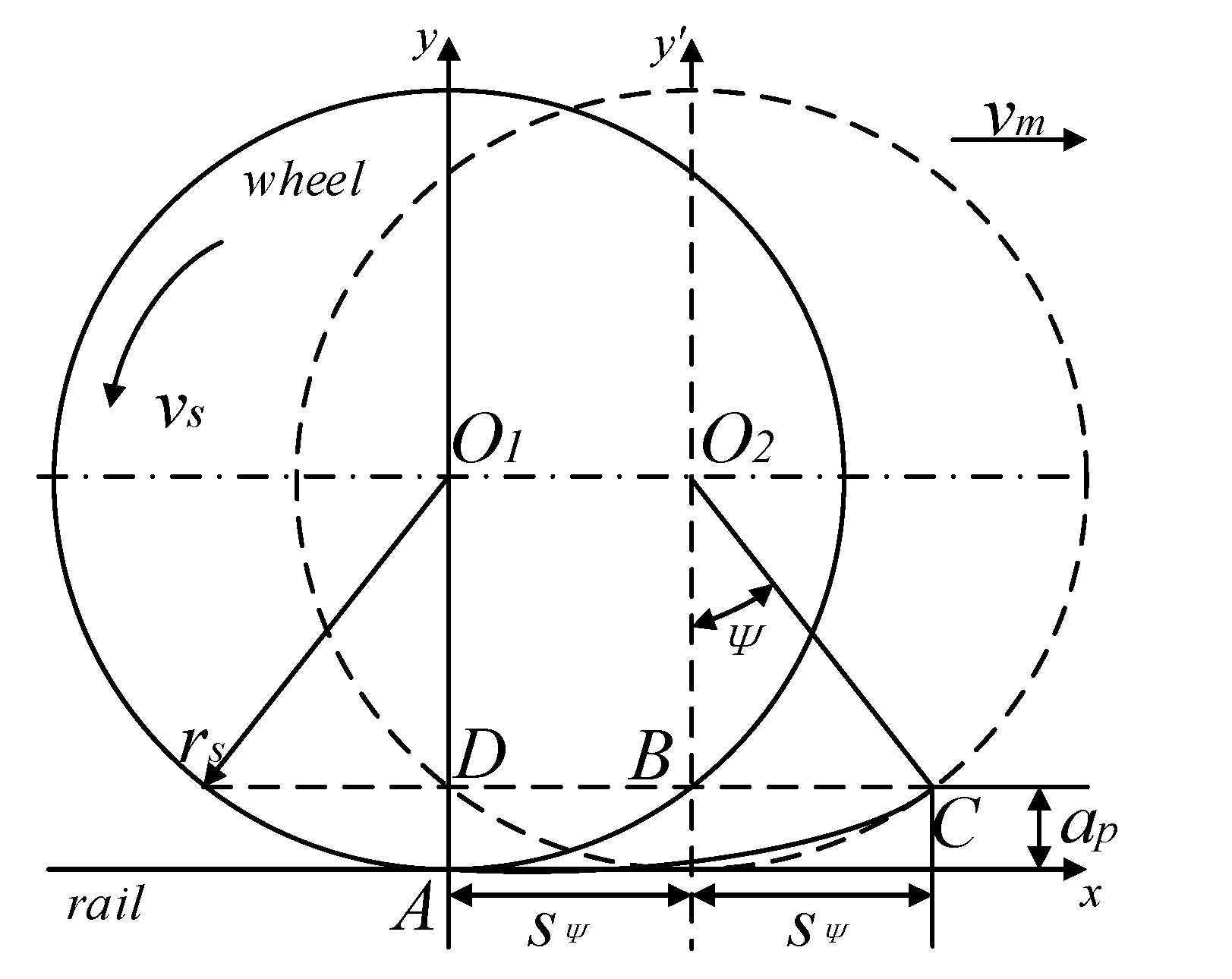
2. Analysis of Kinematic Contact Arc Length

The kinematic contact arc length is one of the most important basic parameters in the grinding process, which is related to almost all grinding parameters. Generally, the schematic diagram for solving the kinematic contact arc length lk between the grinding wheel and the workpiece is shown in Figure 4 [26]. Let the radius of the grinding wheel be rs, and the circumference of the grinding wheel rotate at the linear speed vs. The abrasive grains start grinding the rail at point A, and move horizontally along the longitudinal direction of the rail at the speed vm. When the abrasive grains rotate to point C, the grinding wheel rotates by ψ angle, and the grinding depth of the rail to be ground at this time is ap. Call vs and vm in the same direction at the tangent of point A up-grinding, and the movement in the opposite direction down-grinding. Let the longitudinal displacement of the grinding wheel relative to the rail after one rotation be s0, and the longitudinal displacement along the rail after the grinding wheel rotates by ψ angle be sψ; then, the following relationship exists:
s 0 = v m t = v m 2 π r s v s
s ψ = ψ 2 π · s 0 = ψ 2 π 2 π · r s v s v m = v m v s r s ψ
When the end face of the grinding wheel is perpendicular to the horizontal plane and only deviates from the longitudinal section of the rail by θ, the movement diagram of the grinding wheel is shown in Figure 5. Among these, the dotted line indicates the position of the grinding wheel after kinematic movement along the longitudinal direction of the rail when an abrasive grain is ground from point A to point C.
Combined with Figure 4 and Figure 5, xOy coordinate system is established at the point A where abrasive grains start grinding, and the motion track equation of the grinding wheel relative to the rail is established in Equation (3) [27]. See Section Nomenclature for the parameters involved in the following calculation, where “+” means up-grinding of the grinding wheel, and “−” means down-grinding of the grinding wheel.
{ x = r s s i n ψ ± s ψ c o s θ y = r s r s c o s ψ
Substitute Equation (2) into Equation (3) and then differentiate to get Equation (4).
{ d x = r s ( c o s ψ ± v m v s c o s θ ) d ψ d y = r s s i n ψ d ψ
Then, the differential expression of the wheel–rail kinematic contact arc length is Equation (5).
d l k θ = d x 2 + d y 2 = r s ( c o s ψ ± v m v s c o s θ ) 2 + s i n 2 ψ d ψ
Because the angle ψ is very small (approaching to 0), take sinψ ≈ 0 and cosψ ≈ 1, Equation (5) is simplified to Equation (6).
d l k θ r s ( 1 ± v m v s c o s θ ) d ψ
The kinematic contact arc length between the grinding wheel and the rail is determined by Equation (7).
l k θ = r s 0 ψ ( 1 ± v m v s c o s θ ) d ψ = r s ( 1 ± v m v s c o s θ ) ψ
In the process of rail grinding, operators will push the grinding machine back and forth on the rail to grind at the rail defect location. Therefore, take i l k 1 as the ratio of the kinematic contact arc length between the up-grinding and down-grinding included angle; take i l k 2 as the ratio of the kinematic contact arc length between the included angle and the non-included angle when the grinding wheel face is angled. Among the following parameters, the 0 of some lower corner marks indicates that there is no included angle at the grinding wheel end face, and θ indicates that there is a deflection angle at the grinding wheel end face. Thus, i l k 1 and i l k 2 can be simplified to Equation (8) and Equation (9), respectively.
i l k 1 = l k θ _ d o w m l k θ _ u p = v s + v m c o s θ v s v m c o s θ
i l k 2 = l k θ l k 0 = v s ± v m c o s θ v s ± v m
According to Equation (8), vs is 30 m/s, and θ varies from 0 to 20 degrees. When vm is between 1 km/h and 6 km/h, the effects of vm and θ on i l k 1 and i l k 2 , shown in Figure 6, can be obtained. According to Equation (9), vm is 4 km/h, and θ varies from 0 to 20 degrees. When vs is between 10 m/s and 40 m/s, the effects of vs and θ on i l k 1 and i l k 2 , shown in Figure 7, can be obtained.
It can be found in Figure 6a: when there is angle θ, i l k 1 will gradually increase along with the increase in vm, and its variation range is about 12%; this difference will be slightly reduced along with the increase in angle θ. It can be found in Figure 6b,c: whether the grinding wheel is in down-grinding or up-grinding, i l k 2 changes monotonically along with the increase in vm, and obviously along with the increase in angle θ, but the value has no obvious change. It can be found in Figure 7a: when there is angle θ, i l k 1 will gradually decrease along with the increase in vs, and its variation range is about 20%. With the increase in angle θ, this difference will be slightly reduced. It can be found in Figure 7b,c: whether the grinding wheel is in down-grinding or up-grinding, i l k 2 changes monotonically along with the increase in vs, but the change trend gradually decreases, and it changes obviously along with the increase in angle θ.
From the above analysis, it can be seen that the increase in vs and angle θ will appropriately reduce the difference (ratio i l k 1 reduces) of the kinematic contact arc length in up-grinding and down-grinding, while the effect of vm is opposite. When the grinding wheel is in up-grinding, the increase in angle θ and vm will slightly increase the difference of the kinematic contact arc length of the grinding wheel (ratio i l k 2 decreases), but the effect of vs is opposite. When the grinding wheel is in down-grinding, the increase in vm and angle θ will slightly increase the difference of the kinematic contact arc length of the grinding wheel (ratio i l k 2 increases), but the effect of vs is opposite. With the increase in θ value, the overall change is more obvious.

3. Analysis of Grinding Contact Area

By observing and measuring the wheel-rail grinding contact area, we can get the position relationship between the grinding wheel and the rail, and analyze the grinding effect of the grinding wheel in the later stage. At the center of the rail tread, the wheel-rail grinding contact area (approximately a rectangle) when the end face of the grinding wheel has no included angle is shown in Figure 8. The wheel-rail grinding contact area (approximately a parallelogram) when the end face of the grinding wheel has an included angle is shown in Figure 9. W1 and W2 are the grinding widths of the end face of the grinding wheel, without deflection angle and with deflection angle, respectively, and bD is the thickness of the grinding wheel.
The contact area without included angle is Equation (10).
S 0 = W 1 l k 0 = b D r s ( 1 ± v m v s ) ψ
According to the geometric relationship, the contact area with the included angle is Equation (11).
S θ = A B A D = l k θ ( b D l k θ t a n θ ) = b D r s · ( 1 ± v m v s c o s θ ) ψ r s 2 ( 1 ± v m v s c o s θ ) 2 ψ 2 t a n θ
Because angle ψ is very small (approaching to 0), the approximate relationship between the grinding width W2 and the deflection angle θ is Equation (12).
W 2 = A D · c o s θ = ( b D B C ) c o s θ = b D c o s θ A B t a n θ · c o s θ = b D c o s θ r s ( 1 ± v m v s c o s θ ) ψ s i n θ b D c o s θ
The approximate relationship between W2, bD, and θ can be found from Equation (12). With the increase in deflection angle θ, the grinding band will gradually narrow. Let it be the ratio of the contact area of the grinding wheel end face with the included angle to that without the included angle. Because ψ angle is very small (approaching to 0), Equations (7), (10) and (11) are combined to obtain Equation (13). It can be found that the expression of i S is consistent with that of i l k 2 , and its conclusion will not be repeated here.
i S = S θ S 0 = b D ( 1 ± v m v s c o s θ ) r s ( 1 ± v m v s c o s θ ) 2 ψ t a n θ b D ( 1 ± v m v s ) ( v s ± v m c o s θ ) ( v s ± v m ) = i l k 2

4. Analysis of Maximum Undeformed Chip Thickness of Abrasive Grains

The maximum undeformed chip thickness of abrasive grains is one of the most important basic parameters in the grinding process, and its theoretical research can provide a theoretical basis for the analysis of grinding force, grinding specific energy, grinding zone temperature, and grinding surface roughness acting on abrasive grains [28]. Assuming that the undeformed chip shape of abrasive grains is rectangular, the average cutting thickness and average grinding width of abrasive grains are a g ¯ and b g ¯ , respectively. The volume of the rail removed by grinding wheel is V1, and the volume of the rail ground by the grinding wheel is V2. Then, in a unit time, when the end face of the grinding wheel has no included angle and has an included angle, the volume of the rail to be ground is Equations (14) and (15).
V 10 = v m W 1 a p
V 1 θ = v m W 2 a p
The rail volumes of steel grinded by grinding wheels with no included angle and included angle on the end face are Equations (16) and (17).
V 20 = ( a ¯ g 0 b ¯ g 0 l k 0 ) v s N d b D
V 2 θ = ( a ¯ g θ b ¯ g θ l k θ ) v s N d A D
where Nd is the dynamically effective cutting edge number of the grinding wheel. Make b ¯ g 0 = C a ¯ g 0 , because the grinding Equations (14) and (16) are equal.
a ¯ g 0 = v m a p C N d v s l k 0
Generally, the maximum undeformed chip thickness a g m a x of an abrasive grain is twice the average undeformed chip thickness a ¯ g , resulting is Equation (19).
a g m a x 0 = 2 a ¯ g 0 = 2 v m a p C N d v s l k 0 = 2 v m a p C N d r s ( v s ± v m ) ψ
Make b ¯ g θ = C a ¯ g θ , which is equal to Equations (15) and (17), to obtain Equation (20).
a ¯ g θ = v m a p W 2 C N d v s l k θ A D
In Figure 9, it can be determined from the geometric relationship that cosθ = W2/AD, and Equation (20) can be converted into Equation (21).
a ¯ g θ = v m a p C N d v s l s θ c o s θ = v m a p c o s θ C N d r s ( v s ± v m c o s θ ) ψ
In the same way, Equation (22) can be obtained.
a g m a x θ = 2 a ¯ g θ = 2 v m a p c o s θ C N d r s ( v s ± v m c o s θ ) ψ
Set i a 1 as the ratio of the maximum undeformed chip thickness of abrasive grains in down-grinding and up-grinding, when the end face of the grinding wheel has a deflection angle, and i a 2 as the ratio of the maximum undeformed chip thickness of abrasive grains in the end face of the grinding wheel, with an included angle and without an included angle, when the grinding wheel is in up-grinding or down-grinding, and substitute the combined Equations (19) and (22) to obtain Equations (23) and (24).
i a 1 = a g m a x θ _ d o w n a g m a x θ _ u p = 2 v m a p c o s θ C N d r s ( v s + v m c o s θ ) ψ 2 v m a p c o s θ C N d r s ( v s v m c o s θ ) ψ = v s v m c o s θ v s + v m c o s θ
i a 2 = a g m a x θ a g m a x 0 = 2 v m a p c o s θ C N d r s ( v s ± v m c o s θ ) ψ 2 v m a p C N d r s ( v s ± v m ) ψ = v s ± v m v s ± v m c o s θ c o s θ
According to Equation (23), vs is 30 m/s, and the variation range of θ is 0 to 20 degrees. When vm is between 1 km/h and 6 km/h, the effects of vm and θ on i a 1 and i a 2 , shown in Figure 10, can be obtained. According to Equation (24), when vm is 4 km/h and θ changes from 0 to 20 degrees, vs is between 10 m/s and 40 m/s, and the effects of vs and θ on i a 1 and i a 2 , shown in Figure 11, are obtained.
It can be seen from Figure 10a: when there is angle θ, i a 1 will gradually decrease along with the increase in vm, and its variation range is about 6%, and this difference will be slightly reduced along with the increase in angle θ. It can be found from Figure 10b,c: whether the grinding wheel is in down-grinding or up-grinding, i a 2 changes monotonically along with the increase in vm, and obviously changes along with the increase in angle θ, with the change range of about 5%. It can be found from Figure 11a that when there is angle θ, i a 1 will increase along with the increase in vs, but the change trend will gradually decrease, and angle θ will slightly decrease this difference. From Figure 11b,c, it can be found: whether the grinding wheel is in down-grinding or up-grinding, i a 2 changes monotonically along with the increase in vs, but the change trend gradually decreases, and the change is obvious along with the increase in angle θ, and its change range is about 3%.
It can be seen from the above analysis that the increase in vs and angle θ will appropriately reduce the difference of the maximum undeformed chip thickness between up-grinding and down-grinding (the ratio i a 1 increases), but the effect of vm is opposite. When the grinding wheel is in up-grinding, the increase of vm will slightly reduce the difference of the maximum undeformed chip thickness (the ratio i a 2 increases), but the effect of angle θ is opposite and changes obviously. When the grinding wheel is in down-grinding, the increase in vm and angle θ will appropriately increase the difference of the maximum undeformed chip thickness (the ratio i a 2 reduces), but the effect of vs is opposite. With the increase in θ value, the overall change of i l k 2 is more obvious.

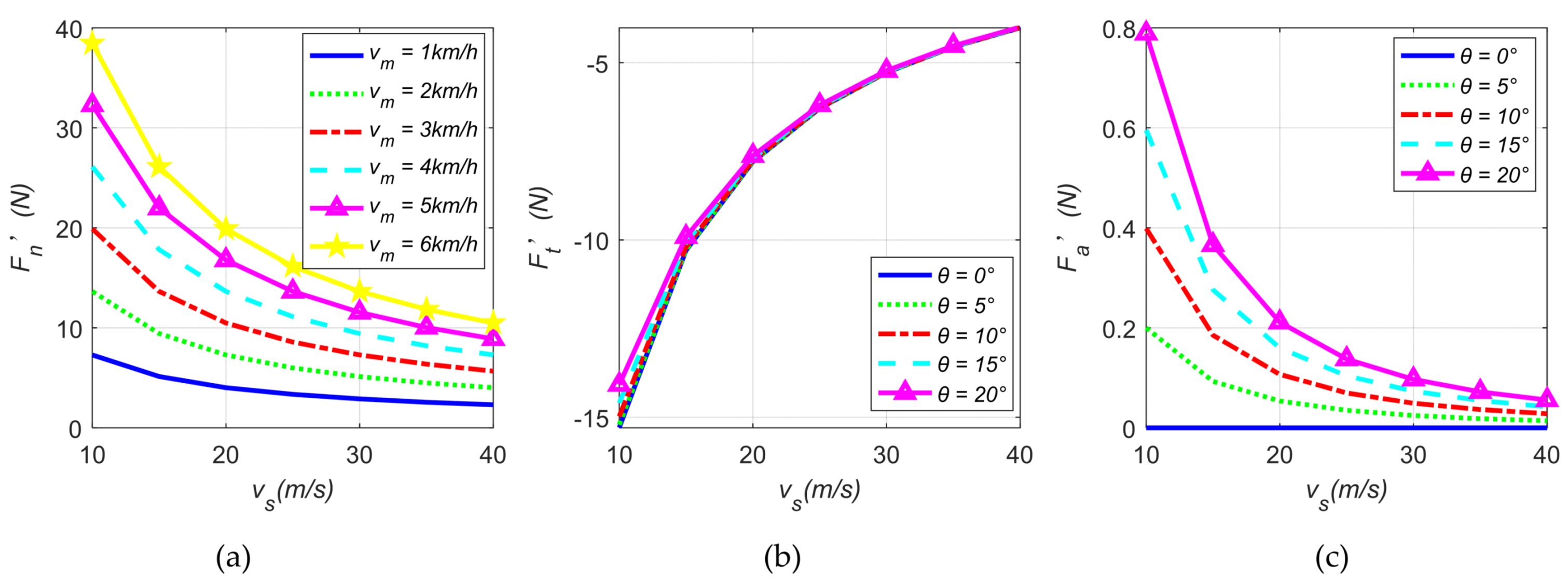
5. Analysis of Grinding Force Model

According to the traditional grinding mechanism for grinding metal materials, the grinding force F acting on the grinding wheel can be divided into three components (perpendicular to each other): the normal grinding force Fn along the radial direction of the grinding wheel, the tangential grinding force Ft along the tangential direction of the grinding wheel, and the axial grinding force Fa along the rotational axis of the grinding wheel. Because the axial component of the grinding wheel when grinding with the circumferential surface is small, it is usually ignored in the research process. However, in the grinding operation, there will be an included angle θ between the end face of the grinding wheel and the feeding direction of the grinding wheel, so the axial component Fa cannot be ignored under this working condition, and its magnitude and direction will change at any time during the reciprocating movement of the grinding machine.
Take the geometric center of the ground rail by the grinding wheel as the origin and establish a spatial coordinate system. The end face of the grinding wheel deflects θ from the longitudinal direction of the rail, and the force on the grinding wheel where the rail is ground is shown in Figure 12 (the y axis is perpendicular to the origin of the plane and faces outwards).
From Figure 12, it can be found that the linear speed of the grinding wheel at the grinding place is vs. When the grinding wheel moves longitudinally on the rail at the speed vm, the abrasive grain combined velocity at the origin O is v, and it forms a φ angle with the x axis. In order to conform to the actual situation as much as possible, the mathematical model of grinding force includes cutting deformation force and friction force. At this time, the tangential force F1, caused by friction, and the tangential force F2, caused by cutting deformation, are not on the plane perpendicular to the axis of the grinding wheel (i.e., not on the x axis, as shown in Figure 12, but in the opposite direction to the combined velocity of the abrasive grain at the origin. The tangential force and axial force caused by friction and cutting deformation are obtained by projecting F1 and F2 on the x axis and z axis, respectively, so as to obtain the tangential force and axial force of the grinding wheel during grinding. Moreover, the direction of the axial grinding force will change when the grinding wheel grinds forward and backward. Let the normal grinding force along the radial direction of the grinding wheel be F, the tangential grinding force along the tangential direction of the grinding wheel be F, and the axial grinding force along the rotational axis of the grinding wheel be F. When the grinding wheel is up-grinding, it can obtain Equation (25).
{ F n θ = F n c θ + F n s θ F t θ = F t c θ + F t s θ F a θ = F a c θ + F a s θ
In Figure 12a, by decomposing and synthesizing vm and v in the xOz plane coordinate, it can obtain Equation (26).
{ v x = v s + v m c o s θ v z = v m s i n θ
It can be found that the angle θ of the grinding wheel end face makes the tangential force F1, caused by friction, and the tangential force F2, caused by cutting deformation, opposite to the closing speed v, and the included angle φ is Equation (27),
ϕ = a r c t a n v z v x = a r c t a n v m s i n θ v s ± v m c o s θ
where “+” means up-grinding and “−” means down-grinding. Set δ ¯ as the average blunt top area of an abrasive grain (that is, the actual contact area between the abrasive grain and the rail), p ¯ θ as the average contact pressure between the grinding wheel surface and the rail, and μ as the friction coefficient between the grinding wheel and the rail. For a single abrasive grain, the normal grinding force Fgnsθ and tangential grinding force Fgtsθ, caused by friction, are Equation (28).
{ F g n s θ = δ ¯ P ¯ θ F g t s θ = μ δ ¯ P ¯ θ c o s ϕ
where, for a single abrasive grain, the normal grinding force Fgncθ and tangential grinding force Fgtcθ, caused by pure shear deformation, are Equation (29) [29].
{ F g n c θ = K A θ F g t c θ = π 4 t a n γ K A θ c o s ϕ
where, K is the grinding force per unit grinding area, Aθ is the grinding cross-sectional area, and γ is the half cone angle when the abrasive grains are assumed to be cones, with an average value of 52 degrees [30]. Combined with Figure 12, it can be found that the axial grinding force of grinding wheel grains is not zero at this time. The normal force, tangential force, and axial force of a single abrasive grain obtained by combining Equations (28) and (29) are Equation (30).
{ F g n θ = F g n c θ + F g n s θ = K A θ + δ ¯ P ¯ θ F g t θ = F g t c θ + F g t s θ = π K A θ 4 t a n γ c o s ϕ μ δ ¯ P ¯ θ c o s ϕ F g a θ = F g a c θ + F g a s θ = ± π K A θ 4 t a n γ s i n ϕ ± μ δ ¯ P ¯ θ s i n ϕ
where, “+” in F g a θ indicates up-grinding, and “−” in F g a θ indicates down-grinding. The normal grinding force F ¯ n θ of all abrasive grains acting on the unit grinding width of the grinding wheel is Equation (31).
F n θ = F n c θ + F n s θ = K · A θ l k θ + N δ ¯ · P ¯ 0 = K · v w v s a p + N δ ¯ · P ¯ 0
where, A θ l k θ is the unit grinding width abrasive cutting rail cross-sectional area sum, they have the following relationship.
A θ l k θ = a e q = v m v s a p
N is total number of cutting abrasive grains per unit grinding width, which can be obtained by integrating the dynamic grinding edge number Nd(l) in any geometric contact arc length range.
N = 0 l k N d ( l ) d l = 0 l k A g c 1 β ( v m v s ) α ( a p d ) α 2 ( l l s ) α d l = A g 1 + α c 1 β ( v m v s ) α a p 1 + α 2 d 1 α 2
Ag is the proportional coefficient of static cutting edge number, c1 is the correlation coefficient of cutting edge density, d is the diameter of the grinding wheel, and α and β are related to the distribution of abrasive grains on the grinding wheel (generally α > 0, β < 1). Substitute Equations (32) and (33) into Equation (31) to simplify and get Equation (34).
F n θ = K · v m v s a p + c ( v m v s ) α · a p 1 + α 2
where, c = A g δ ¯ p ¯ c 1 β d 1 α 2 / ( 1 + α ) . Li et al. [31] obtained the grinding force model from the relationship between grinding amount and grinding force by means of plunge grinding on the cylindrical grinder, and solved K, c, and α by changing the values of experimental parameters vm, vs, and ap for different materials. Because the Brinell hardness (HBW) of hot-rolled rail is between 260 and 360 [32], which is not much different from the value converted from Rockwell hardness (HRC24) of #45 steel in the literature [31], Equation (34) can be converted into Equation (35).
F n θ = F n c θ + F n s θ = 108500 · v m v s a p + 256.4 ( v m v s ) 0.33 · a p 0.665 2
Then, the tangential grinding force F t θ of all abrasive grains acting on the unit grinding width of grinding wheel is Equation (36).
F t θ = F t c θ + F t s θ = π 4 t a n γ F n c θ c o s φ μ · F n s θ c o s φ = 108500 π 4 t a n γ · v m v s a p c o s φ 256.4 μ ( v m v s ) 0.33 · a p 0.665 2 c o s φ
All axial grinding forces F a θ of all abrasive grains acting on the unit grinding width of the grinding wheel are Equation (37).
F a θ = F a c θ + F a s θ = π 4 t a n γ F n c θ s i n φ μ · F n s θ s i n φ = ± 108500 π 4 t a n γ · v m v s a p s i n φ ± 256.4 μ ( v m v s ) 0.33 · a p 0.665 2 s i n φ  
where, the half cone angle γ of the abrasive grain takes 52 degrees, the grinding depth ap of the grinding wheel takes 0.002 mm, and the friction coefficient μ between the brown corundum grinding wheel and the rail takes 0.25. When the grinding wheel in up-grinding at a speed vm of 4 km/h in the longitudinal direction of the rail, the effects of vm and vs on the normal grinding force F n θ of all abrasive grains per unit grinding width is shown in Figure 13a, and the effects of vs and θ on Ft and Fa are shown in Figure 13b,c, respectively.
It can be seen from Figure 13a: Fn’ will decrease along with the increase in vs, but the change trend will gradually decrease, and the increase in vm will increase its numerical value as a whole. It can be found from Figure 13b that Ft’ decreases along with the increase in vs, but the change trend gradually decreases, and the increase in angle θ will slightly decrease its numerical value. It can be found from Figure 13c that the change trend of Fa’ decreases along with the increase in vs, the increase in angle θ will increase its numerical value as a whole, and the axial force of grinding wheel will increase along with the increase in the grinding width of grinding wheel. When the grinding wheel in down-grinding at a speed vm of 4 km/h in the longitudinal direction of the rail, the direction of axial component Fa is reversed and its value also increases slightly.

6. Conclusions

In view of the influence of the deflection angle of the grinding wheel end face on the grinding parameters and grinding force, and based on the traditional grinding theory, this paper theoretically studied the mathematical models of the wheel-rail kinematic contact arc length, wheel-rail grinding contact area, maximum undeformed chip thickness, and grinding force of the grinding wheel end face with deflection angle, and analyzed the main influence of grinding wheel circumferential speed, grinding wheel kinematic speed, and the deflection angle of the grinding wheel end face on the grinding parameters and force, which has a guiding significance for the structural design, grinding control strategy, and experimental research for rail curved surface grinding machines. In the later stage, grinding force modeling in arbitrary 2D freeform grinding [24], peripheral grinding parameters optimization [20], and the related experimental research on the peripheral grinding of grinding wheel should be carried out in the actual track environment from the aspects of material removal rate, surface roughness, vibration, noise, energy consumption, and temperature change.
The results show that when there is angle θ on the end face of the grinding wheel, peripheral grinding parameters and grinding force have different degrees of influence. The conclusions are as follows:
(1) The changes in vm and vs have an obvious influence on the peripheral grinding parameters (wheel-rail kinematic contact arc length, wheel-rail grinding contact area, and maximum undeformed chip thickness) when the grinding wheel is both up-grinding and in down-grinding.
(2) The difference in the kinematic contact arc length between the up-grinding and down-grinding of the grinding wheel will be appropriately reduced with the increase in vs and angle θ, but the effect of vm is opposite. When the grinding wheel is up-grinding, the increase in angle θ and vm will slightly increase the difference in the kinematic contact arc length of the grinding wheel, but the effect of vs is opposite. When the grinding wheel is down-grinding, the increase in vm and angle θ will slightly increase the difference in the contact arc length of the grinding wheel, but the effect of vs is opposite. With the increase in θ value, the overall change of kinematic contact arc length is more obvious. The expression of the wheel-rail grinding contact area ratio is consistent with that of the kinematic contact arc length ratio, and their conclusions are the same.
(3) The increase in vs angle θ will appropriately reduce the difference of the maximum undeformed chip thickness between up-grinding and down-grinding, but the effect of vm is opposite. When the grinding wheel is up-grinding, the increase in vm will slightly reduce the difference in the maximum undeformed chip thickness, but the effect of angle θ is opposite and changes obviously. When the grinding wheel is down-grinding, the increase in vm and angle θ will appropriately increase the difference in the maximum undeformed chip thickness, but the effect of vs is opposite. With the increase in θ value, the overall change in the maximum undeformed chip thickness of the abrasive grains is more obvious.
(4) The angle θ makes the tangential force F1, caused by friction, and the tangential force F2, caused by cutting deformation, not on the plane perpendicular to the axis of the grinding wheel. However, in the opposite direction to the combined speed v, the included angle is φ, and the axial force cannot be ignored, which will increase along with the increase in grinding width of the grinding wheel. The magnitude and direction of the axial grinding force per unit width of the grinding wheel will change when the grinding wheel grinds backward or forward.

Author Contributions

Conceptualization and supervision, B.C. and C.W.; methodology and formal analysis, C.C.; investigation and data curation, X.G. and X.L.; writing—original draft preparation, C.C.; writing—review and editing, F.G.; project administration, B.C.; funding acquisition, X.G. All authors have read and agreed to the published version of the manuscript.

Funding

This research was funded by the 2020 Science and Technology Research and Development Plan of China Railway Wuhan Bureau Group Co., Ltd., grant number 20G18.

Data Availability Statement

The data presented in this study are available from the corresponding author upon request.

Acknowledgments

The authors would like to thank anonymous reviewers and handling editors for their useful comments and constructive suggestions that helped to improve the quality of this paper.

Conflicts of Interest

The authors declare no conflict of interest.

Nomenclature

rsgrinding wheel radius
apgrinding depth
agmaxmaximum undeformed chip thickness of an abrasive grain
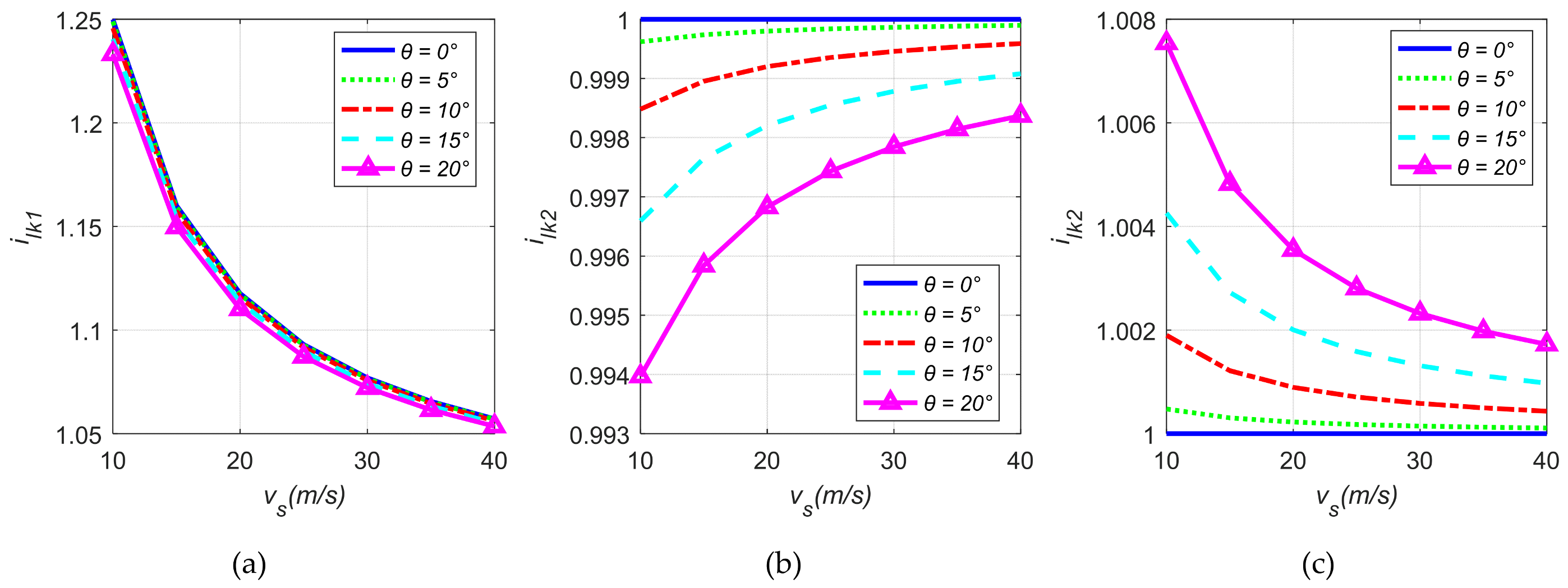
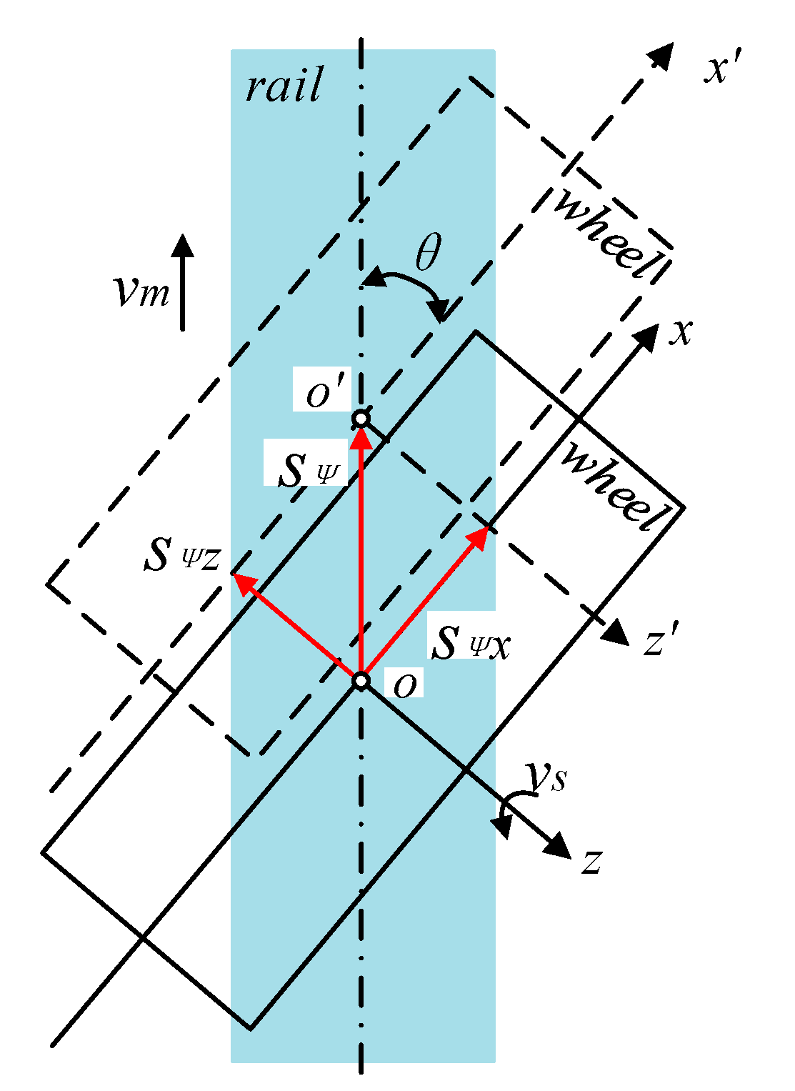
vsgrinding wheel circumferential speed
vmgrinding wheel kinematic speed along rail longitudinal direction
θdeflection angle of the grinding wheel end face along rail longitudinal section
ψthe rotation angle of abrasive grains
φangle between the combined speed v and the x axis direction in the grinding wheel coordinate system
vcombined velocity of vs and vm
vxvelocity component in x axis direction of v
vmxvelocity component in x axis direction of vm
vmzvelocity component in z axis direction of vm grinding wheel coordinate system
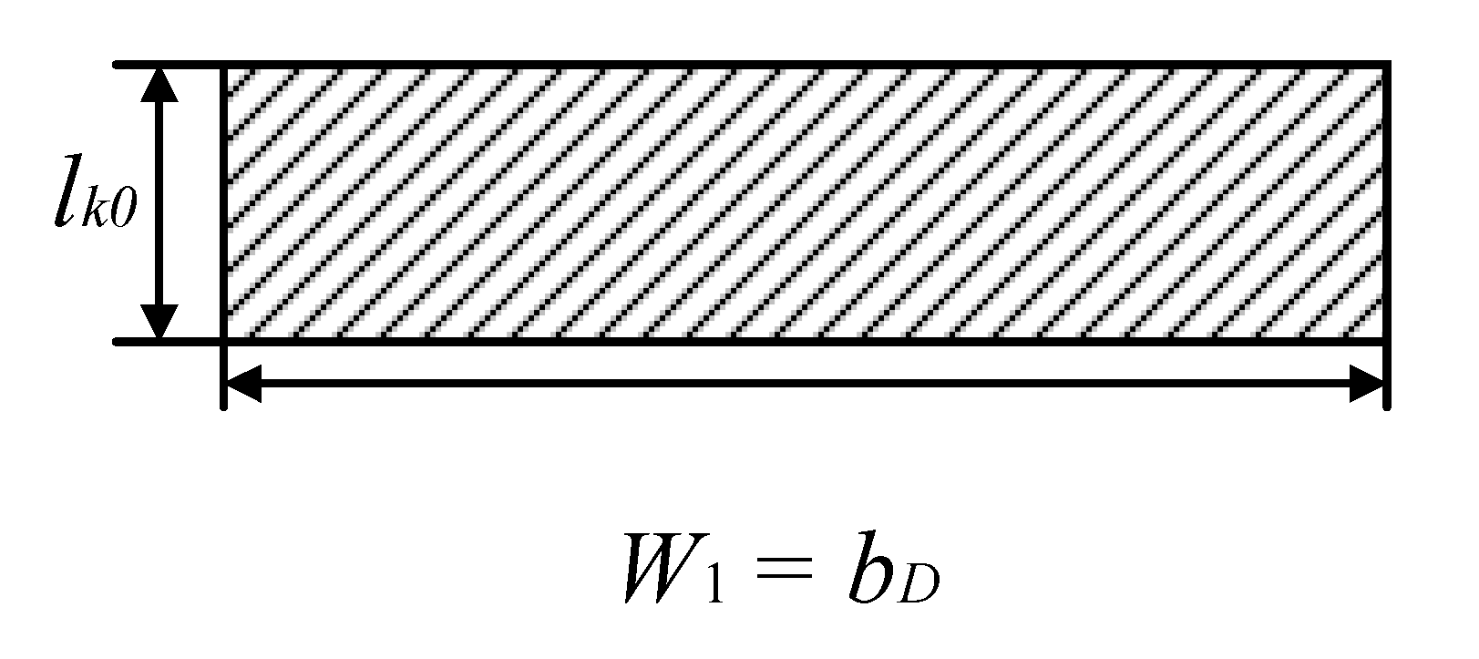
lk0wheel-rail kinematic contact arc length without deflection angle θ
lwheel-rail kinematic contact arc length with deflection angle θ
s0the longitudinal displacement of the grinding wheel relative to the rail after one rotation
sψlongitudinal displacement of grinding wheel relative to rail when rotating ψ angle
Nddynamically effective cutting edge number of the grinding wheel
Ntotal number of cutting abrasive grains per unit grinding width
bDgrinding wheel thickness
W1the grinding widths of the end face of the grinding wheel without deflection angle θ
W2the grinding widths of the end face of the grinding wheel with deflection angle θ
F1tangential force caused by friction
F2tangential force caused by cutting deformation
Ftsθtangential force caused by friction in x direction of grinding wheel coordinate system
Ftcθtangential force caused by cutting deformation in x direction of grinding wheel coordinate system
Fnsθtangential force caused by friction in y direction of grinding wheel coordinate system
Fncθtangential force caused by cutting deformation in y direction of grinding wheel coordinate system
Fasθaxial force caused by friction in z direction of grinding wheel coordinate system
Facθaxial force caused by cutting deformation in z direction of grinding wheel coordinate system

References

  1. TB/T 1778-2010; Catalogue of Rail Defects. Ministry of Railways of the People’s Republic of China: Beijing, China, 2010. (In Chinese)
  2. Department of Track, Communication & Signaling and Power Supply of China State Railway Group Co., Ltd. Railway Permanent-Way Technical Manual · Track; China Railway Publishing House Co., Ltd.: Beijing, China, 2016; pp. 62–70. (In Chinese) [Google Scholar]
  3. Department of Track, Communication & Signaling and Power Supply of China State Railway Group Co., Ltd. Railway Permanent-Way Technical Manual · Turnout; China Railway Publishing House Co., Ltd.: Beijing, China, 2017; pp. 286–287. (In Chinese) [Google Scholar]
  4. Department of Track, Communication & Signaling and Power Supply of China State Railway Group Co., Ltd. Railway Permanent-Way Technical Manual · Line Maintenance; China Railway Publishing House Co., Ltd.: Beijing, China, 2017; pp. 176–185. (In Chinese) [Google Scholar]
  5. Fan, W.G.; Liu, Y.M.; Li, J.Y. Development status and prospect of rail grinding technology for high speed railway. J. Mech. Eng. 2018, 54, 184–193. [Google Scholar] [CrossRef]
  6. Wang, W.; Li, J.; Fan, W. Belt grinding mechanism-based method for roughness profile prediction of the rail surface. J. Braz. Soc. Mech. Sci. 2022, 44, 1–13. [Google Scholar] [CrossRef]
  7. Ding, H.-H.; Han, Y.-C.; Zhou, K.; Huang, Y.-H.; Shi, L.-B.; Guo, J.; Liu, Q.-Y.; Wang, W.-J. Grinding force modeling and experimental verification of rail grinding. Proc. Inst. Mech. Eng. J: J. Eng. Tribol. 2020, 234, 1254–1264. [Google Scholar] [CrossRef]
  8. Zhang, W.; Zhang, P.; Zhang, J.; Fan, X.; Zhu, M. Probing the effect of abrasive grit size on rail grinding behaviors. J. Manuf. Processes 2020, 53, 388–395. [Google Scholar] [CrossRef]
  9. Gu, K.; Lin, Q.; Wang, W.; Wang, H.; Guo, J.; Liu, Q.; Zhu, M. Analysis on the effects of rotational speed of grinding stone on removal behavior of rail material. Wear 2015, 342–343, 52–59. [Google Scholar] [CrossRef]
  10. Ding, H.; Yang, J.; Wang, W.; Guo, J.; Liu, Q. Characterization and formation mechanisms of rail chips from facing grinding by abrasive wheel. J. Manuf. Processes 2022, 73, 544–554. [Google Scholar] [CrossRef]
  11. Lin, B.; Zhou, K.; Guo, J.; Liu, Q.; Wang, W. Influence of grinding parameters on surface temperature and burn behaviors of grinding rail. Tribol. Int. 2018, 122, 151–162. [Google Scholar] [CrossRef]
  12. Zhou, K.; Ding, H.; Wang, R.; Yang, J.; Guo, J.; Liu, Q.; Wang, W. Experimental investigation on material removal mechanism during rail grinding at different forward speeds. Tribol. Int. 2019, 143, 106040. [Google Scholar] [CrossRef]
  13. Liu, P.; Quan, Y.; Wan, J. Experimental investigation on the effects of machining parameters on surface integrity in form grinding of rail material. J. Phys. Conf. Ser. 2021, 1834, 012021. [Google Scholar] [CrossRef]
  14. Uhlmann, E.; Lypovka, P.; Hochschild, L.; Schröer, N. Influence of rail grinding process parameters on rail surface roughness and surface layer hardness. Wear 2016, 366–367, 287–293. [Google Scholar] [CrossRef]
  15. Zhang, S.; Zhou, K.; Ding, H.; Guo, J.; Liu, Q.; Wang, W. Effects of Grinding Passes and Direction on Material Removal Behaviours in the Rail Grinding Process. Materials 2018, 11, 2293. [Google Scholar] [CrossRef] [PubMed] [Green Version]
  16. Liu, P.; Quan, Y.; Wan, J.; Yu, L. Experimental Investigation on the Wear and Damage Behaviors of Machined Wheel-Rail Materials under Dry Sliding Conditions. Materials 2021, 14, 540. [Google Scholar] [CrossRef] [PubMed]
  17. Liu, P.-Z.; Zou, W.-J.; Peng, J.; Song, X.-D.; Xiao, F.-R. Study on the Effect of Grinding Pressure on Material Removal Behavior Performed on a Self-Designed Passive Grinding Simulator. Appl. Sci. 2021, 11, 4128. [Google Scholar] [CrossRef]
  18. Pereverzev, P.P.; Pimenov, D.Y. A grinding force model allowing for dulling of abrasive wheel cutting grains in plunge cylindrical grinding. J. Frict. Wear 2016, 37, 60–65. [Google Scholar] [CrossRef]
  19. Jamil, M.; He, N.; Zhao, W.; Xiang, H.; Gupta, M.K.; Iqbal, A.; Khan, A.M. Assessment of energy consumption, carbon emissions and cost metrics under hybrid MQL-Dry ice blasting system: A novel cleaner production technology for manufacturing sectors. J. Clean. Prod. 2022, 360, 132111. [Google Scholar] [CrossRef]
  20. Khan, A.M.; Jamil, M.; Mia, M.; Pimenov, D.Y.; Gasiyarov, V.R.; Gupta, M.K.; He, N. Multi-Objective Optimization for Grinding of AISI D2 Steel with Al2O3 Wheel under MQL. Materials 2018, 11, 2269. [Google Scholar] [CrossRef] [PubMed] [Green Version]
  21. Xiong, X. Design and Analysis of Rail Surface Grinding Device. Master’s Thesis, Chongqing University of Technology, Chongqing, China, 2021. (In Chinese). [Google Scholar]
  22. Wang, W.; Li, J.; Fan, W.; Hou, G. A numerical model to investigate contact status for rail grinding by abrasive belt with an axial deflection. J. Braz. Soc. Mech. Sci. Eng. 2019, 41, 494. [Google Scholar] [CrossRef]
  23. Zhou, K.; Ding, H.; Zhang, S.; Guo, J.; Liu, Q.; Wang, W. Modelling and simulation of the grinding force in rail grinding that considers the swing angle of the grinding stone. Tribol. Int. 2019, 137, 274–288. [Google Scholar] [CrossRef]
  24. Wu, H.; Yao, Z.Q. Force modeling for 2D freeform grinding with infinitesimal method. J. Manuf. Processes 2021, 70, 108–120. [Google Scholar] [CrossRef]
  25. Miao, T.Y. Research on Mechanism of Dry Grinding of Railway Steel. Master’s Thesis, Hunan University, Changsha, China, 2018. (In Chinese). [Google Scholar]
  26. Ren, J.X.; Hua, D.A. Grinding Theory; Northwestern Polytechnical University Press: Xi’an, China, 1988; pp. 33–85. (In Chinese) [Google Scholar]
  27. Li, B.M.; Li, Q.; Zhao, B. Abrasive, Abrasive Tool and Grinding Technology; Chemical Industry Press: Beijing, China, 2016; pp. 116–188. [Google Scholar]
  28. Malkin, S. Grinding Technology: Theory and Applications of Machining with Abrasives, 2nd ed.; Industrial Press Inc.: New York, NY, USA, 2008; pp. 43–79. [Google Scholar]
  29. Eiji, U. Cutting and grinding machining (Part I); Kyoritsu Shuppan Co., Ltd.: Tokyo, Japan, 1971. (In Chinese) [Google Scholar]
  30. Dou, L.Y. Study On The Performance of High Efficiency Grinding for Grinding Rail with New Composite Grinding Wheel. Master’s Thesis, Nanjing University of Aeronautics and Astronautics, Nanjing, China, 2019. (In Chinese). [Google Scholar]
  31. Li, L.J.; Fu, J.C. A Study of Grinding Force Mathematical Model. J. Hunan Univ. Nat. Sci. 1979, 3, 43–55. (In Chinese) [Google Scholar]
  32. GB/T 2585-2021; Hot-Rolled Steel Rails for Railway. State Administration for Market Regulation: Beijing, China, 2021. (In Chinese)
Figure 1. Schematic diagram of rail section.
Metals 12 01209 g001
Figure 2. Relationship between rail life and damage according to grinding methods.
Metals 12 01209 g002
Figure 3. Small rail grinding machine: (a) copying grinder; (b) turnout grinder; (c) plane grinder.
Metals 12 01209 g003
Figure 4. Schematic diagram of abrasive grain movement track.
Metals 12 01209 g004
Figure 5. Schematic diagram of grinding wheel end face deflection, θ movement.
Metals 12 01209 g005
Figure 6. Effects of vm and θ on i l k 1 and i l k 2 : (a) effects of vm and θ on i l k 1 ; (b) effects of vm and θ on i l k 2 in up-grinding; (c) effects of vm and θ on i l k 2 in down-grinding.
Metals 12 01209 g006
Figure 7. Effects of vs and θ on i l k 1 and i l k 2 : (a) effects of vs and θ on i l k 1 ; (b) effects of vs and θ on i l k 2 in up-grinding; (c) effects of vs and θ on i l k 2 in down-grinding.
Metals 12 01209 g007
Figure 8. Area of contact area without included angle.
Metals 12 01209 g008
Figure 9. Area of contact area with included angle.
Metals 12 01209 g009
Figure 10. Effects of vm and θ on i a 1 and i a 2 : (a) effects of vm and θ on i a 1 ; (b) effects of vm and θ on i a 2 in up-grinding; (c) effects of vm and θ on i a 2 in down-grinding.
Metals 12 01209 g010
Figure 11. Effects of vs and θ on i a 1 and i a 2 : (a) effects of vs and θ on i a 1 ; (b) effects of vs and θ on i a 2 in up-grinding; (c) effects of vs and θ on i a 2 in down-grinding.
Metals 12 01209 g011
Figure 12. Schematic diagram of the grinding force of the grinding wheel in a horizontal plane when the end face of the grinding wheel has an included angle: (a) up-grinding; (b) down-grinding.
Metals 12 01209 g012
Figure 13. Effects of vm, vs, and θ on grinding force: (a) effects of vs and vm on Fn’; (b) effects of vs and θ on Ft’; (c) effects of vs and θ on Fa’.
Metals 12 01209 g013
Publisher’s Note: MDPI stays neutral with regard to jurisdictional claims in published maps and institutional affiliations.

