Article

The Microstructure and the Properties of 304 and 430 Steel Foams Prepared by Powder Metallurgy Using CaCl2 as a Space Holder

1
Faculty of Materials Science and Engineering, Kunming University of Science and Technology, Kunming 650093, China
2
State Key Laboratory for Advanced Metals and Materials, University of Science and Technology Beijing, Beijing 100083, China
*
Authors to whom correspondence should be addressed.
Metals 2022, 12(7), 1182; https://doi.org/10.3390/met12071182
Submission received: 21 June 2022 / Revised: 4 July 2022 / Accepted: 7 July 2022 / Published: 12 July 2022
(This article belongs to the Special Issue Synthesis and Applications of Metallic Foams)

Abstract

:
In order to prepare stainless steel foams (SSFs) with high specific strength, cost-effective performance, and multiple relative density ranges, this work used CaCl2 as a space holder to prepare 304 and 430 SSF samples with different relative densities using the powder metallurgy method. The microstructure and the properties were compared and analyzed by optical microscope (OM), scanning electron microscope (SEM), energy dispersive spectrometer (EDS), X-ray diffraction (XRD), and a universal testing machine. The results show that the matrix of 304 SSFs is austenite and 430 is ferrite. In the quasi-static compression test, when the relative density was in the range of 0.33~0.12, their compressive strength increased with the relative density increasing; the maximum compressive strength of 304 SSFs reached 40.29 MPa and that of 430 SSFs was 49.79 MPa. While the compressive strength of 430 SSFs is significantly higher than 304 SSFs at a similar relative density, 304 SSFs show better stability in the plastic deformation stage. When the deformation reached densification, the maximum energy absorption value of 304 SSFs reached 15.94 MJ/m3, while 430 SSFs was 22.70 MJ/m3. The energy absorption value increased with the relative density increasing, and 430 SSFs exhibited a higher energy absorption capacity than 304 SSFs.

1. Introduction

Steel foams (SFs) is a new structural functional material developed in recent years. It has many excellent properties endowed by metal matrix and porous structure. Compared with traditional solid steel, SFs have the advantages of high specific strength and stiffness, high specific surface area, light weight, energy absorption and shock absorption, filtration, heat dissipation and insulation, electromagnetic shielding, biocompatibility, etc. [1,2]. In addition, compared with aluminum foams and other low melting point and low strength metal foams, SFs have the advantages of high compressive strength, impact resistance, and high weldability [3,4,5,6]. Therefore, SFs have a broad application prospect in aerospace, automobiles and ships, construction engineering, heat dissipation and insulation, catalytic filtration, electromagnetic shielding, and biomedical fields [7,8,9,10].
Due to the high melting point of steel, compared with aluminum foams, copper foams, and other low melting point metal foams, the preparation of SFs is difficult and costly, which restricts the development and the application of SFs. In recent years, with technical progress, the preparation technology of SFs has also been continuously developed. At present, the main processes for preparing SFs include polymer impregnation [7,10], Lotus-type/Gasar [11,12,13], hollow sphere [6,14,15], additive manufacturing [16,17,18], and powder metallurgy-space holder [3,19,20,21]. Among these methods, polymer impregnation is mainly used to prepare high porosity open-cell steel foams that have poor strength, which produces toxic gases when removing the polymer template. The Lotus-type/Gasar method is mainly used to prepare low porosity SFs, and the cell shape is not easy to control. The hollow sphere and the additive manufacturing methods have high equipment requirements, a complicated process, and high cost. The powder metallurgy-space holder is a simple and an economical method, which can obtain the SFs with a flexible and a controllable cell shape, a pore diameter, and relative density. Mondal et al. [22] used NH4HCO3 as a space holder to prepare 316L SSFs with different relative densities by powder metallurgy. Jain et al. [5,21] used urea as a space holder to prepare 316L SSFs by powder metallurgy. Guo et al. [2] and Zhang et al. [4] prepared 316L SSFs and 400 series SSFs with different porosity by powder metallurgy, using CaCl2 as a space holder.
At present, the research, development, and application of SFs are mainly focused on 316L stainless steel foams (SSFs). Because of its excellent characteristics—high temperature resistance and corrosion resistance—it was commonly used as filter materials in high temperature corrosive and biomedical environments. However, due to its higher price, it is not suitable to fabricate large structural components. In 300 series austenitic stainless steel, compared with 316L, 304 austenitic stainless steel has a lower Ni content, no molybdenum, and a higher carbon content. Therefore, its price is relatively cheap. It has certain advantages in preparing large and light SSF components. In 400 series ferritic stainless steel, Zhang et al. [4] compared the microstructure and the properties of 410L and 430L SSFs, and they found that 430L SSFs have better mechanical properties and corrosion resistance. However, in contrast to 430L with a lower carbon content, 430 is cheaper, and it has better application value in preparing large and light energy absorbing SSF components.
Therefore, we chose the cheaper 304 and 430 stainless steel as research objects; 304 austenitic SSFs and 430 ferritic SSFs with different relative densities are prepared by powder metallurgy, using CaCl2 as a space holder. The effects of a matrix microstructure and relative density on mechanical properties and energy absorption properties are studied. This work will provide the technological and the theoretical basis for the preparation of the lightweight, high-strength, and cost-effective SFs that could be used to make light shock absorption and energy absorption components.

2. Materials and Methods

2.1. Materials

Produced by Handan aisier atomized powder Co., Ltd. (Handan, China), 304 and 430 stainless steel powders were used as raw materials, and the particle size was 38 μm. The chemical composition of the two powders was detected by the chemical analysis method and the high frequency induction infrared absorption method; the chemical composition is shown in Table 1. Anhydrous CaCl2 spherical particle was used as a space holder produced by Xilong Scientific Co., Ltd. (Shantou, China), with a size range of 1.9–2.4 mm and a melting point of 782 °C. Ethanol (purity ≥ 99.8%) was used as an adhesive.

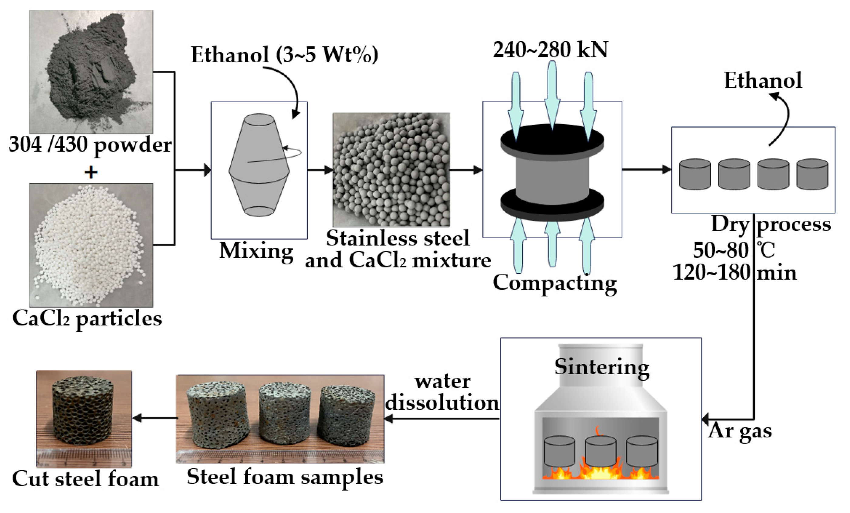
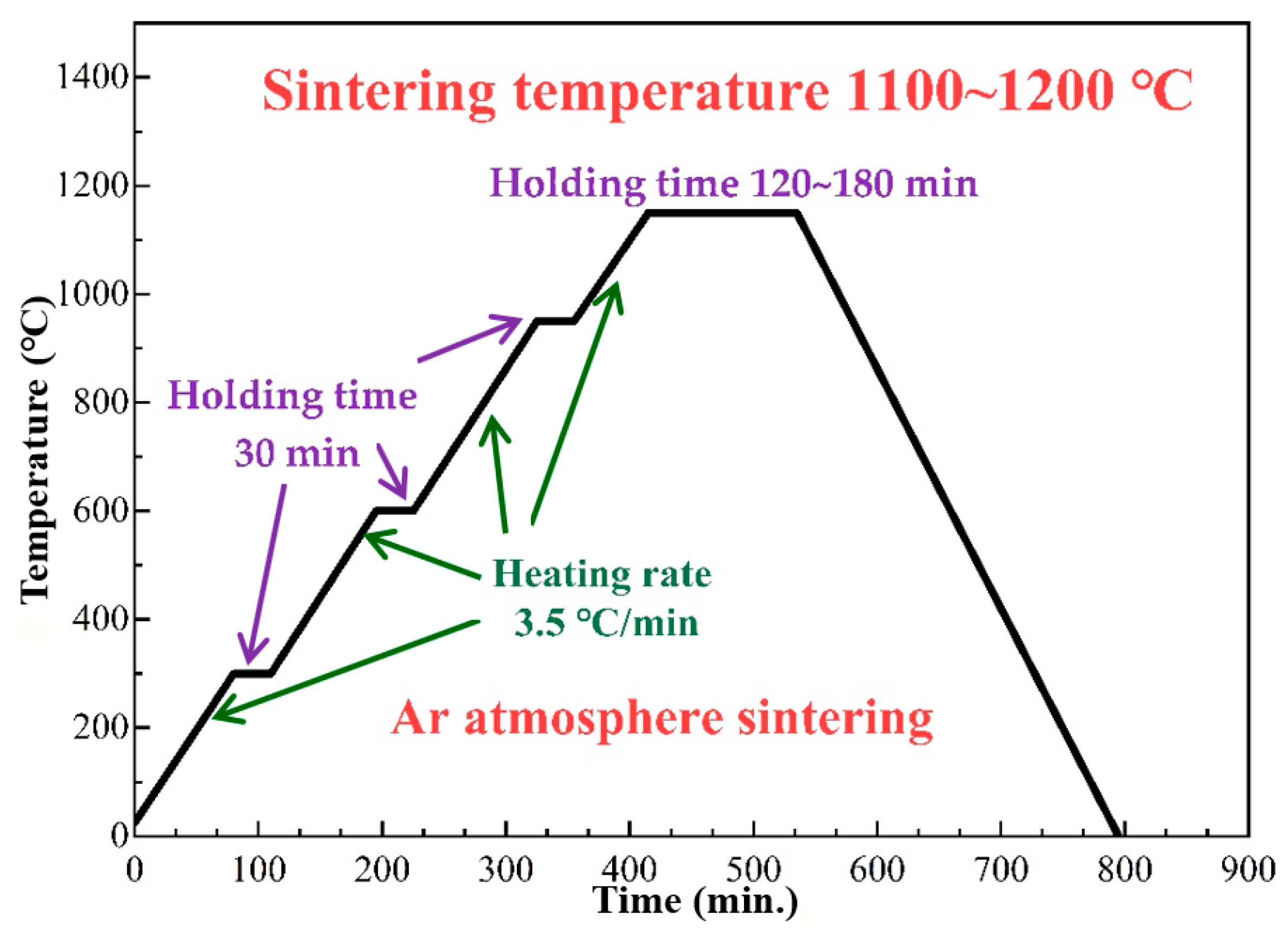
2.2. Production Process

The stainless steel foam (SSF) samples were manufactured by the powder metallurgy (CaCl2 as space hold) method, and the schematic diagram of the preparation process is shown in Figure 1. The 304 and the 430 stainless steel powders were mixed with spherical CaCl2 particles according to different volume fractions, respectively, adding ethanol in the mixing process. The mixed powders were compacted under a 240–280 kN pressure to prepare 32 mm (ϕ) × 25 mm (H) precursors. The precursors were dried at a low temperature to remove ethanol and then sintered in a high-temperature atmosphere furnace (under the condition of argon). The sintering temperature was 1100–1200 °C for 2–3 h. The heating process is shown in Figure 2. Finally, after removing residual CaCl2 by water dissolution, 304 and 430 SSF samples with different relative densities were obtained.

2.3. Characterization of SSF Samples

In order to compare the corrosion resistance of 304 and 430 SSFs, the SSF samples were cut and polished and then corroded with a mixed solution of concentrated hydrochloric acid and deionized water (the ratio was 5:2, the corrosion time was 5 min), and the microstructure was observed with an optical microscope (OM, ZEISS EVO18, Carl Zeiss VISION (China) Ltd., Oberkochen, Germany) and a scanning electron microscope (SEM, NOVA NANOSEM 450, FEI Company, Hillsboro, OR, USA). The composition and the structure of 304 and 430 SSFs were analyzed by scanning electron microscope (SEM), energy dispersive spectrometer (EDS), and X-ray diffraction (XRD). The quasi-static compression test was carried out with a universal testing machine (AGX-V, Shimadzu (Shanghai) Co., Ltd., Shanghai, China), the sample size was 30 mm (ϕ) × 25 mm (H), and the moving rate of the head was 1 mm/min. The apparent density of the SSF samples was calculated by Archimedes.

3. Results and Discussion
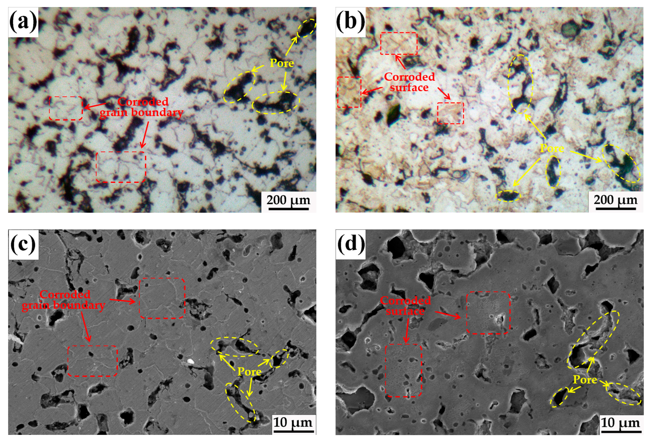
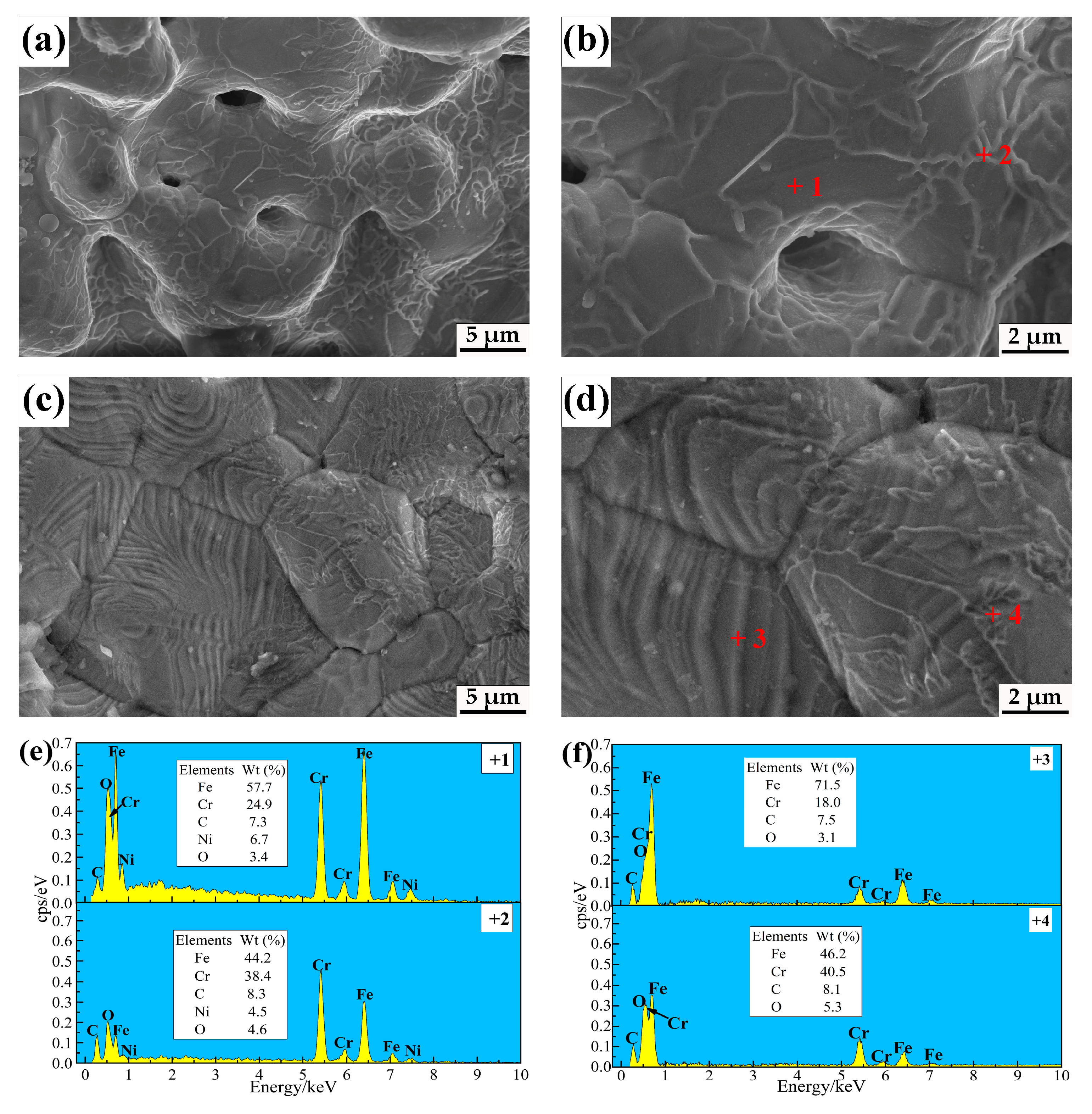
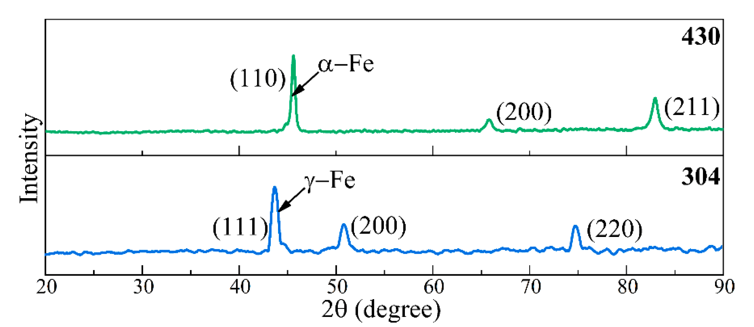
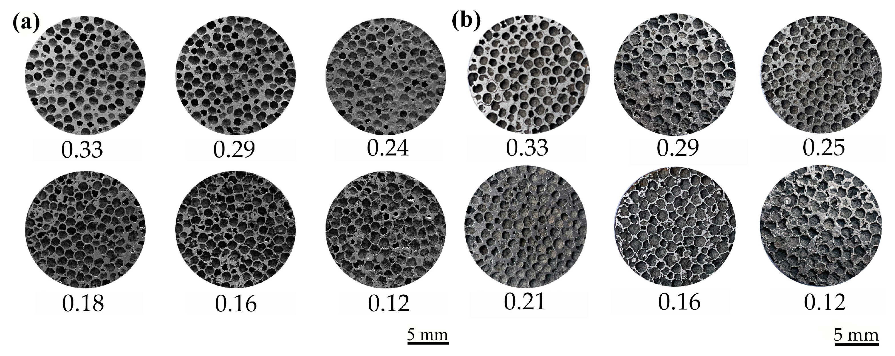
3.1. Microstructure

Figure 3 shows optical microscope (OM) and scanning electron microscope (SEM) images of the surface structure of the matrix of the 304 and the 430 stainless steel foam (SSF) samples corroded by a concentrated hydrochloric acid solution. Under the same corrosive conditions, it can be seen from Figure 3a that the corrosion of the 304 sample mainly occurs along the grain boundary, and the grain surface is flat and smooth. Figure 3b shows that the corrosion of the 430 sample mainly occurs on the grain surface, and the surface corrosion is serious. It is believed that the overall corrosion resistance of the 304 sample is higher than that of the 430. The reason is that 304 has a higher chromium content than 430 as well as higher nickel, and chromium and nickel are beneficial to improving corrosion resistance. Figure 3c,d shows SEM images of the 304 and the 430 SSFs matrix after corrosion, respectively. The SEM analysis shows that under the same corrosion conditions, the grain surface of 304 SSFs is smooth and not obviously corroded, while the grain surface of 430 SSF is rough and obviously corroded, which further confirms that the overall corrosion resistance of 304 SSFs is higher than that of 430.
Figure 4a,c shows scanning electron microscope (SEM) images of the cell wall of the 304 and the 430 SSF samples, respectively. Figure 4b,d shows local zone enlarged images. Figure 4a,c shows that metal particles bond together to form grains by sintering at high temperature, and micropores are formed by sintering the shrinkage between grains. Figure 4b shows that a large amount of “network” structure is formed on the matrix surface of 304 SSFs. According to the energy dispersive spectrometer (EDS) composition analysis of two points in Figure 4e, point 1 (Figure 4b) corresponds to the matrix, and the “network” structure of point 2 (Figure 4b) contains higher chromium, indicating that it is a kind of Cr-rich oxide. It can be seen from Figure 4d that a large amount of “wrinkle” structure and a small amount of “network” structure are present on the matrix surface of 430 SSFs. According to the EDS composition analysis of two points in Figure 4f, the “wrinkle” structure of point 3 (Figure 4d) is mainly composed of Fe and Cr elements, which is speculated to be a kind of Fe and Cr mixed oxide, and the “network” structure of point 4 (Figure 4d) on the matrix surface of 430 SSFs is also a Cr-rich oxide, the same as on 304 SSFs. It shows that there are two kinds of oxides on the matrix surface of 430 SSFs. In addition, no CaCl2 was found in EDS analysis, indicating that the CaCl2 agent had been completely removed.
Figure 5 shows the X-ray diffraction (XRD) spectrum of 304 and 430 SSFs. The blue and green X-ray spectrum represent the spectrum of 304 and 430 SSFs, respectively. It can be concluded that the 304 SSF samples correspond to the (111) (200) (220) diffraction peak of γ-Fe, indicating that the matrix structure is γ-Fe; 430 SSF samples correspond to the (110) (200) (211) diffraction peak of α-Fe, indicating that the matrix structure is α-Fe. In addition, there were no other diffraction peaks, indicating that residues of the space holder were not found in the two SSF samples.

3.2. Compressive Behavior of SSF Samples

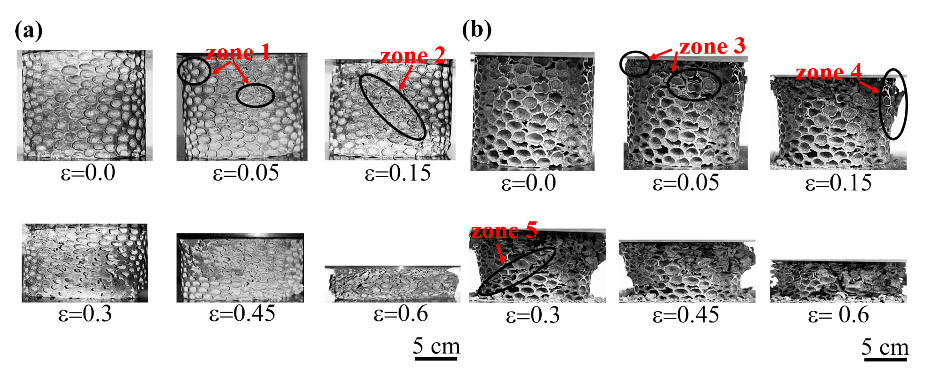
3.2.1. Cell Morphology and Evolution of Deformation

Figure 6a,b shows the cell morphology of 304 and 430 stainless steel foams (SSFs) with different relative densities. It can be seen that the cell shape is relatively uniform and near spherical, similar to the shape of the space holder. The thickness of the cell wall gradually decreases with the relative density decreasing.
Figure 7 shows the quasi-static axial compressive deformation process of 304 and 430 stainless steel foam (SSF) samples. It can be seen from Figure 7a that when the strain is less than 0.05, the deformation of 304 SSF samples first occurs in the position of local irregular cells, such as zone 1. Due to the irregular cell shape, stress concentration is easy to occur and leads to cell collapse and local zone deformation. When the strain exceeds 0.15, the deformation band (zone 2) begins to form at a certain angle with the load direction, then propagates across the specimen as the load increases. When the strain exceeds 0.6, the sample tends to be densified. As can be seen from Figure 7b, when the strain is less than 0.05, the deformation of 430 SSF samples also first occurs in the irregular cell shape zone, such as zone 3. When the strain reaches 0.15, brittle collapse occurs in the local cell wall (zone 4). With the load increasing, a new deformation band (zone 5) is formed, while the previous deformation zone continues to expand and fracture. When the strain exceeds 0.6, the whole sample is crushed. By comparing the two deformation processes, it can be seen that 304 SSFs show better toughness than 430 SSFs.

3.2.2. Stress–Strain Behavior

Figure 8 shows the stress–strain curves of 304 and 430 stainless steel foam (SSF) samples with different relative densities. The deformation mechanism can be described as three typical deformation stages: initial elastic deformation, a long deformation plateau, and a densification region. In the initial elastic deformation region, the stress is proportional to the strain, while the stress in the edges and in the walls of cell exceeds the yield strength (σys) of the solid, the onset of plasticity is reached, a long plateau region is caused by the plastic collapse of cells, and finally with strain increasing, the densification region is reached in which the cell is compacted and the stress increases rapidly. However, the stress–strain curves of 304 and 430 SSFs are obviously different in the plastic deformation stage. For 304 SSF samples, the stress remains nearly constant as the strain increases, the plastic deformation plateau keeping stable. For 430 SSF samples, the stress fluctuates up and down with the strain increasing, the plastic deformation plateau is unstable, which indicates that local brittle collapse occurs, as shown in Figure 7b.
The dots in Figure 8 represent the compressive strength of the SSFs, and Table 2 shows the compressive strength of two kinds of SSF samples corresponding to different relative densities. It can be seen that the compressive strength of 304 and 430 SSFs decreases with the decrease of relative density, and the compressive strength of 430 SSFs is higher than 430 SSFs under a similar relative density. The reason is that the carbon content in the 430 raw powder is higher than in 304; generally, the increase in carbon content will lead to an increase in strength and a decrease in toughness, while nickel in 304 is good for improving toughness but not strength.

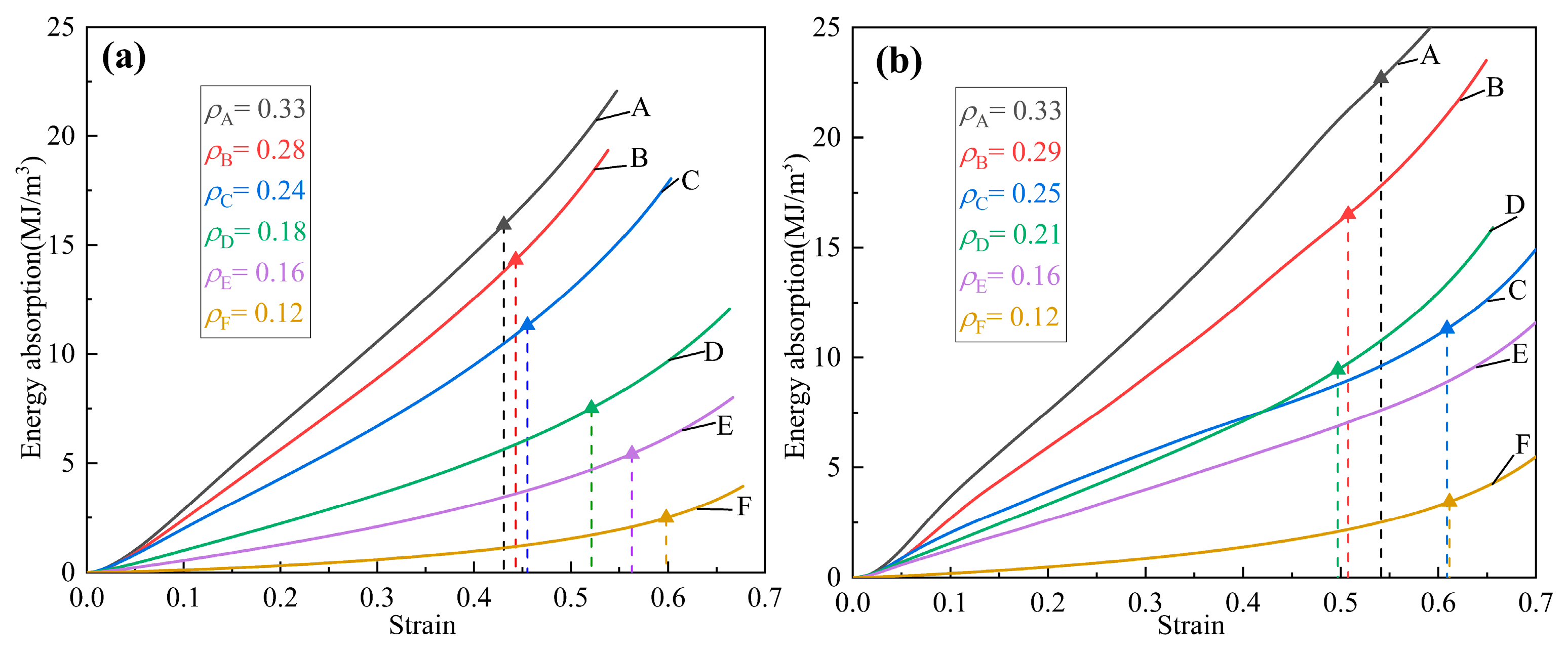
3.2.3. Energy Absorption

The stainless steel foams (SSFs) show good energy absorption characteristics during compression deformation. The energy absorption value is an important index that represents the energy absorption characteristics of metal foams. The energy absorption value (W) refers to the absorbed energy when the unit volume sample is compressed to densification ( ε D ). The absorption energy for a sample can be calculated by integrating the area under the stress–strain curve [23], namely:
W = 0 ε D σ ( ε ) d ε
where W is the energy absorption value per unit volume of the SSF samples; ε D is the strain of densification; and σ ( ε ) represents the stress corresponding to strain. Figure 9 shows the relation of the energy absorption value and the strain of the SSFs. The triangular symbol represents the energy absorption value of the SSF samples with different relative densities when compressed to densification. The detailed energy absorption values of 304 and 430 SSFs with different relative densities are shown in Table 3. It can be seen that the energy absorption value of 304 and 430 SSFs decreases with the decrease of relative density. However, the energy absorption value of 430 SSFs is higher than that of 304 SSFs at a similar relative density.
The corrosion resistance and the toughness of 304 stainless steel foams (SSFs) are better than 430, while the strength and the energy absorption of 430 SSFs are higher than 304; the main reason is the difference in their matrix structure and composition. The 304 SSFs matrix contains higher nickel and lower carbon, which is conducive to improving its corrosion resistance and toughness. The 430 SSFs matrix contains higher carbon and no nickel, which is beneficial to enhancing its strength and energy absorption. According to the characteristics of 304 and 430 SSFs, they can be used in different environments. Because 304 SSFs have better corrosion resistance and toughness, they can be used as a stable absorbing energy component for harsh environments. The 430 SSFs have excellent mechanical properties and energy absorption properties, and the raw material price is relatively cheap; it can be used to fabricate a large absorbing energy component for atmosphere and marine environments.

4. Conclusions

In this work, 304 and 430 stainless steel foams (SSFs) with different relative densities were successfully prepared by powder metallurgy using CaCl2 as a space holder. The matrix structure of 304 SSFs is γ-Fe and that of 430 SSFs is α-Fe. Compared with 430 SSFs, 304 SSFs have higher corrosion resistance.
In the plastic deformation stage during the compression process, for 304 SSF samples, the stress remains nearly constant with the strain increasing, and the plastic deformation plateau is stable, showing good toughness. For the 430 SSF samples, the stress fluctuates up and down with the strain increasing, and the plastic deformation plateau is unstable, indicating that local zone brittle collapse occurs. The 304 SSFs show better toughness than the 430 SSFs.
While the relative density of SSFs is in the range of 0.33~0.12, the compressive strength of 304 SSFs is 40.29–0.81 MPa, and that of 430 SSFs is 49.79–1.5 MPa, and the compressive strength decreases with the decrease of relative density. At the same relative density, the compressive strength of 430 SSFs is higher than that of 304 SSFs. The energy absorption value of 304 SSFs is 15.94–2.47 MJ/m3, for 430 SSFs it is 22.70–3.39 MJ/m3, and the energy absorption value decreases with the decrease of relative density. At the same relative density, 430 SSFs show a higher capacity of energy absorption than 304 when it is compressed to densification.
The corrosion resistance and the toughness of 304 SSFs are better than 430 SSFs. The 304 SSFs can be used as a light energy-absorption component with higher strength and stability in harsh environments (acid and alkali environment). The strength and the energy absorption of the 430 SSFs are higher than the 304 SSFs, and its cost performance is higher. Thus, 430 SSFs can be used as a large light energy-absorption component for atmosphere and marine environments.

Author Contributions

Conceptualization, Y.Z. and G.Z.; methodology, J.L.; investigation, J.L. and S.S.; resources, Y.Z., X.Z. and H.W.; writing—original draft preparation, J.L.; writing—review and editing, Y.Z. and J.L.; supervision, Y.Z. and X.Z. All authors have read and agreed to the published version of the manuscript.

Funding

This research was funded by the National Natural Science Foundation of China (Grant No. 51861020). Hui Wang acknowledges the financial support from the National Natural Science Foundation of China (Grant No. 51971017) and the Fundamental Research Fund for the Central Universities of China (FRF-TP-18-004C1).

Institutional Review Board Statement

Not applicable.

Informed Consent Statement

Not applicable.

Data Availability Statement

Not applicable.

Conflicts of Interest

The authors declare no conflict of interest.

References

  1. Smith, B.H.; Szyniszewski, S.; Hajjar, J.F.; Schafer, B.W.; Arwade, S.R. Steel foam for structures: A review of applications, manufacturing and material properties. J. Constr. Steel Res. 2012, 72, 276. [Google Scholar] [CrossRef]
  2. Guo, K.S.; Li, M.C.; Gong, Q.; Li, C.S.; Li, C.H.; Zhong, H.; Zhou, Y. Experimental investigation on steel foams fabricated by sintering-dissolution process. Mater. Manuf. Process 2016, 31, 1597–1602. [Google Scholar] [CrossRef]
  3. Hsu, C.M.; Tzeng, Y.C.; Chen, S.F.; Chen, Y.L.; Lee, H.L. Fabrication of 17-4PH stainless steel foam by a pressureless powder space holder technique. Adv. Eng. Mater. 2021, 23, 2001202. [Google Scholar] [CrossRef]
  4. Zhang, G.; Yuan, T.; Ma, D.; Zhou, P.; Guo, C.; Zhou, Y.; Zuo, X. Comparision of structure and performance for foamed stainless steels 410L and 430L. Chin. J. Mater. Res. 2021, 35, 597–605. [Google Scholar]
  5. Jain, H.; Mondal, D.P.; Gupta, G.; Kumar, R.; Singh, S. Synthesis and characterization of 316L stainless steel foam made through two different removal process of space holder method. Manuf. Lett. 2020, 26, 33–36. [Google Scholar] [CrossRef]
  6. Rabiei, A.; Karimpour, K.; Basu, D.; Janssens, M. Steel-steel composite metal foam in simulated pool fire testing. Int. J. Therm. Sci. 2020, 153, 106336. [Google Scholar] [CrossRef]
  7. Jain, H.; Kumar, R.; Gupta, G.; Mondal, D.P. Microstructure, mechanical and EMI shielding performance in open cell austenitic stainless steel foam made through PU foam template. Mater. Chem. Phys. 2020, 242, 122273. [Google Scholar] [CrossRef]
  8. Wang, C.H.; Jiang, F.C.; Shao, S.Q.; Yu, T.M.; Guo, C.H. Acoustic properties of 316L stainless steel hollow sphere composites fabricated by pressure casting. Metals 2020, 10, 1047. [Google Scholar] [CrossRef]
  9. Mutlu, I.; Oktay, E. Characterization of 17-4 PH stainless steel foam for biomedical applications in simulated body fluid and artificial saliva environments. Mater. Sci. Eng. C-Mater. 2013, 33, 1125–1131. [Google Scholar] [CrossRef]
  10. Xu, X.B.; Liu, P.S.; Chen, G.F.; Li, C.P. Sound absorption performance of highly porous stainless steel foam with reticular structure. Met. Mater. Int. 2021, 27, 3316–3324. [Google Scholar] [CrossRef]
  11. Nakajima, H. Fabrication, mechanical and physical properties, and its application of lotus-type porous metals. Mater. Trans. 2019, 60, 2481–2489. [Google Scholar]
  12. Ide, T.; Tane, M.; Ikeda, T.; Hyun, S.K.; Nakajima, H. Compressive properties of lotus-type porous stainless steel. J. Mater. Res. 2006, 21, 185–193. [Google Scholar]
  13. Ikeda, T.; Aoki, T.; Nakajima, H. Fabrication of lotus-type porous stainless steel by continuous zone melting technique and mechanical property. Metall. Mater. Trans. A 2005, 36, 77–86. [Google Scholar] [CrossRef]
  14. Szyniszewski, S.T.; Smith, B.H.; Hajjar, J.F.; Schafer, B.W.; Arwade, S.R. The mechanical properties and modeling of a sintered hollow sphere steel foam. Mater. Des. 2014, 54, 1083–1094. [Google Scholar]
  15. Fiedler, T.; Veyhl, C.; Belova, I.V.; Bernthaler, T.; Heine, B.; Murch, G.E. Mechanical properties and micro-deformation of sintered metallic hollow sphere structure. Comp. Mater. Sci. 2013, 74, 143–147. [Google Scholar] [CrossRef]
  16. Prashanth, K.G.; Löber, L.; Klauss, H.-J.; Kühn, U.; Eckert, J. Characterization of 316L steel cellular dodecahedron structures produced by selective laser melting. Technologies 2016, 4, 34. [Google Scholar] [CrossRef] [Green Version]
  17. Caiazzo, F.; Campanelli, S.L.; Cardaropoli, F.; Contuzzi, N.; Sergi, V.; Ludovico, A.D. Manufacturing and characterization of similar to foam steel components processed through selective laser melting. Int. J. Adv. Manuf. Technol. 2017, 92, 2121–2130. [Google Scholar] [CrossRef] [Green Version]
  18. Capek, J.; Machova, M.; Fousova, M.; Kubasek, J.; Vojtech, D.; Fojt, J.; Jablonska, E.; Lipov, J.; Ruml, T. Highly porous, low elastic modulus 316L stainless steel scaffold prepared by selective laser melting. Mater. Sci. Eng. C-Mater. 2016, 69, 631–639. [Google Scholar] [CrossRef]
  19. Sazegaran, H.; Naserian Nik, A.M.; Akbari, M.R.; Akbari Nejad Fogh, A. Investigation on the compressive behavior of steel foams manufactured by powder metallurgy route. J. Metall. Mater. Eng. 2021, 32, 45–56. [Google Scholar]
  20. Sazegaran, H. Investigation on production parameters of steel foam manufactured through powder metallurgical space holder technique. Met. Mater. Int. 2021, 27, 3371–3384. [Google Scholar] [CrossRef]
  21. Jain, H.; Mondal, D.P.; Gupta, G.; Kumar, R. Effect of compressive strain rate on the deformation behaviour of austenitic stainless steel foam produced by space holder technique. Mater. Chem. Phys. 2021, 259, 124010. [Google Scholar] [CrossRef]
  22. Mondal, D.P.; Jain, H.; Das, S.; Jha, A.K. Stainless steel foams made through powder metallurgy route using NH4HCO3 as space holder. Mater. Des. 2015, 88, 430–437. [Google Scholar] [CrossRef]
  23. Ashby, M.F.; Evans, T.; Fleck, N.A.; Hutchinson, J.W.; Wadley, H.N.G.; Gibson, L.J. Properties of metal foams. In Metal Foams: A Design Guide; Butterworth Heinemann: Oxford, UK, 2000; Volume 4, pp. 40–54. [Google Scholar]
Figure 1. The schematic diagram of preparation process for SSF samples.
Metals 12 01182 g001
Figure 2. The schematic diagram of heating cycle for sintering SSF samples.
Metals 12 01182 g002
Figure 3. The OM and SEM images of the SSF matrix. (a,b) are OM photos of 304 and 430 SSF respectively; (c,d) are SEM images of 304 and 430 SSF, respectively.
Metals 12 01182 g003
Figure 4. SEM images and EDS spectrum of the cell wall of the SSFs. (a,b) the SEM images of 304 SSFs; (c,d) the SEM images of 430 SSFs; (e,f) the EDS analysis map of 304 and 430 SSFs, respectively.
Metals 12 01182 g004
Figure 5. XRD spectrum of 304 and 430 SSFs.
Metals 12 01182 g005
Figure 6. The cell morphology of the SSFs with different relative densities: (a) 304; (b) 430.
Metals 12 01182 g006
Figure 7. Evolution of deformation of SSFs during compression (a) 304; (b) 430.
Metals 12 01182 g007
Figure 8. The stress–strain curve of the SSF samples with different relative densities: (a) 304; (b) 430.
Metals 12 01182 g008
Figure 9. The relation of energy absorption value and strain at different relative densities: (a) 304; (b) 430.
Metals 12 01182 g009
Table 1. The chemical composition of 304 and 430 stainless steel powders (wt.%).
MaterialsCSiMnPSCrNiFe
304≤0.08≤1.00≤2.00≤0.045≤0.03018–208–10.5Bal.
430≤0.12≤1.00≤2.00≤0.04≤0.03016–180Bal.
Table 2. The compressive strength of SSF samples. (MPa).
304   ρ R D . Compressive Strength 430   ρ R D . Compressive Strength
0.3340.290.3349.79
0.2832.300.2938.00
0.2423.700.2526.65
0.1813.530.2117.91
0.166.200.1615.32
0.120.810.121.50
Table 3. The energy absorption value of the 304 and 430 SSFs (MJ/m3).
304   ρ R D . Energy Absorption Value 430   ρ R D . Energy Absorption Value
0.33115.940.3322.70
0.2814.310.2916.51
0.2411.320.2511.34
0.187.510.219.47
0.165.440.167.82
0.122.470.123.39
Publisher’s Note: MDPI stays neutral with regard to jurisdictional claims in published maps and institutional affiliations.

