Article

Research on Rapid and Accurate Fixture Design for Non-Intervention Machining of Complex Parts

1
School of Mechanical Engineering & Automation, Beihang University, Beijing 100191, China
2
Beijing Xinghang Electro-Mechanical Equipment Co., Ltd., Beijing 100074, China
3
College of Mechanical and Electrical Engineering, Nanjing University of Aeronautics and Astronautics, Nanjing 210016, China
*
Author to whom correspondence should be addressed.
Metals 2022, 12(7), 1174; https://doi.org/10.3390/met12071174
Submission received: 12 May 2022 / Revised: 23 June 2022 / Accepted: 7 July 2022 / Published: 10 July 2022

Abstract

:
Aerospace parts have the characteristics of complex shape and high machining accuracy, the machining processes of which is complicated and diverse. Numerous special tooling fixtures need to be designed to ensure the smooth implementation of the machining process. In particular, the cabins of the aircraft have thin-walled, weakly rigid, complex, and special-shaped curved structures, the clamping alignment of which is difficult because of a great deal of human influence and poor versatility. In response to the above problems, off-machine clamping technology was investigated, which supports the non-intervention processing of flexible production lines. Then, a scheme suitable for accurate transmission of benchmarks was proposed. A cabin’s mathematical model of casting clamping force analysis was established. Immediately afterwards, the optimization of clamping project was realized by a finite element analysis method based on clamping force and deformation control. The off-machine clamping scheme was designed to realize rapid positioning and accurate datum transmission between flexible tooling and parts, flexible tooling, and equipment. Finally, the designed scheme was implemented through a case to verify its feasibility.

1. Introduction

Aerospace equipment plays an important role in industry [1,2,3]. It has the characteristic of poor consistency and is difficult to transfer its machining data and to ensure the wall thickness and the size of butt assembly features [4]. The traditional manufacturing process has some problems due to the complex process flow of the complex cabin, such as the easy occurrence of accumulation errors due to multiple clampings. The machining accuracy of the parts is hard to ensure, which is limited by the effect of the difference in the alignment accuracy of manual clamping [5]. The consuming time for clamping the complex cabins is longer than its processing time, and the utilization rate of most machining equipment is less than 30%. It can be seen that the clamping tooling is an important part to affect the machining accuracy and the benchmark transmission, which directly influences product quality, production efficiency, and processing cost [6,7]. According to a study by the Boeing Company on machining deformation of four aircraft projects, the economic losses of parts rework and scrap due to machining deformation exceeded 290 million USD [8].
According to the above background, the fixing system used in the manufacturing process of thin-walled parts, which provide correct support and prevent accidental deformation, requires special attention to design [9]. The traditional “3–2–1” fixing principle was not enough for this kind of thin-walled parts [10]. Therefore, many scholars have proposed lots of novel clamping designs and advanced clamping systems to apply in actual production activities [11]. Qi et al. [12] designed a variable multipoint and multi-degree-of-freedom flexible fixture, and the mathematic description model of the fixture movement process was established based on the topological theory, which greatly improves the accuracy of clamping. Aurrekoetxea et al. [13] proposed a new idea in workholding to clamp the workpiece. The clamping force generated by the fixture is responsible for flattening the specimen, which enables the removal of constant thickness layers. Rex et al. [14] presented a novel method for the fixture layout to contribute to the automation of fixture layout design in flexible fixture systems. This model greatly shortens equipment downtime and improves production efficiency in flexible production applications. Ma et al. [15] studied the influence of the characteristics of magnetorheological fluid fixtures on workpiece dynamics and vibration suppression in machining. They proposed a new fixture design method to improve the dynamic machining ability of flexible workpieces. Wang et al. [16] designed a flexible special fixture for clamping thin-walled parts using the characteristics of low melting point alloys, which can fit thin-walled parts with arbitrary complex structures. Wang et al. [17] designed a new type of flexible fixture based on the principle of multiple dynamic vibration absorbers. In addition, they established the hybrid dynamic model of concentrated mass method and the finite element method for thin-walled parts and flexible fixtures. Wang et al. [18] transformed the fixture design problem with continuous variables into a discrete workpiece stability analysis problem. Immediately afterwards, they proposed an iterative programming method of multi-point clamping force based on linear programming.
Moreover, the finite element analysis (FEA) method is used by many researchers to study the fixture system of thin-walled parts. Wu ed al. [19] studied the relationship between the clamping force and the maximum deformation workpiece through the finite element analysis method and established an empirical model of the relationship between the clamping force and the maximum deformation. Then, a reasonable tightening sequence was obtained to minimize the maximum deformation. Wang et al. [20] proposed a parametric finite element analysis (FEA) system method for thin-walled parts, which could evaluate the need for supporting fixtures in the light of tolerance requirements. Wang et al. [21] proposed a new location layout optimization method based on the flower pollination algorithm. The location layout optimization of thin-walled parts was carried out by combining the flower pollination algorithm and the FEA method. Su et al. [22] established a finite element model to determine five clamping schemes, which, due to the workpiece, exhibits different degrees of deformation under clamping in actual situations. Then, the optimal scheme was obtained, and the optimal methods can quickly evaluate and select the milling clamping scheme for thin-walled parts.
The above researchers have mainly conducted exploration and research on the clamping force, clamping arrangement, and clamping method. However, only minority factors were considered in the above research. The influence of the combined action on the deformation of the clamped parts has not been analyzed. The coupling connection between the above factors was ignored, which resulted in difficulties to achieve rapid and accurate fixture of the parts. Aiming at the development of aerospace manufacturing, this paper proposes a rapid and accurate fixture design (RAFD) method based on non-intervention machining mode, which is used to resolve the problems of low machining accuracy, difficulty in clamping alignment, large influence of human factors, and poor versatility. A mathematical model was established for analysis of the clamping force, and a finite element analysis method was used to realize the optimization of the clamping plan based on the clamping force and deformation control. Additionally, the off-machine clamping and alignment device of the machine tool was designed to realize the fast positioning and accurate clamping, which can utilize on flexible machine and parts.

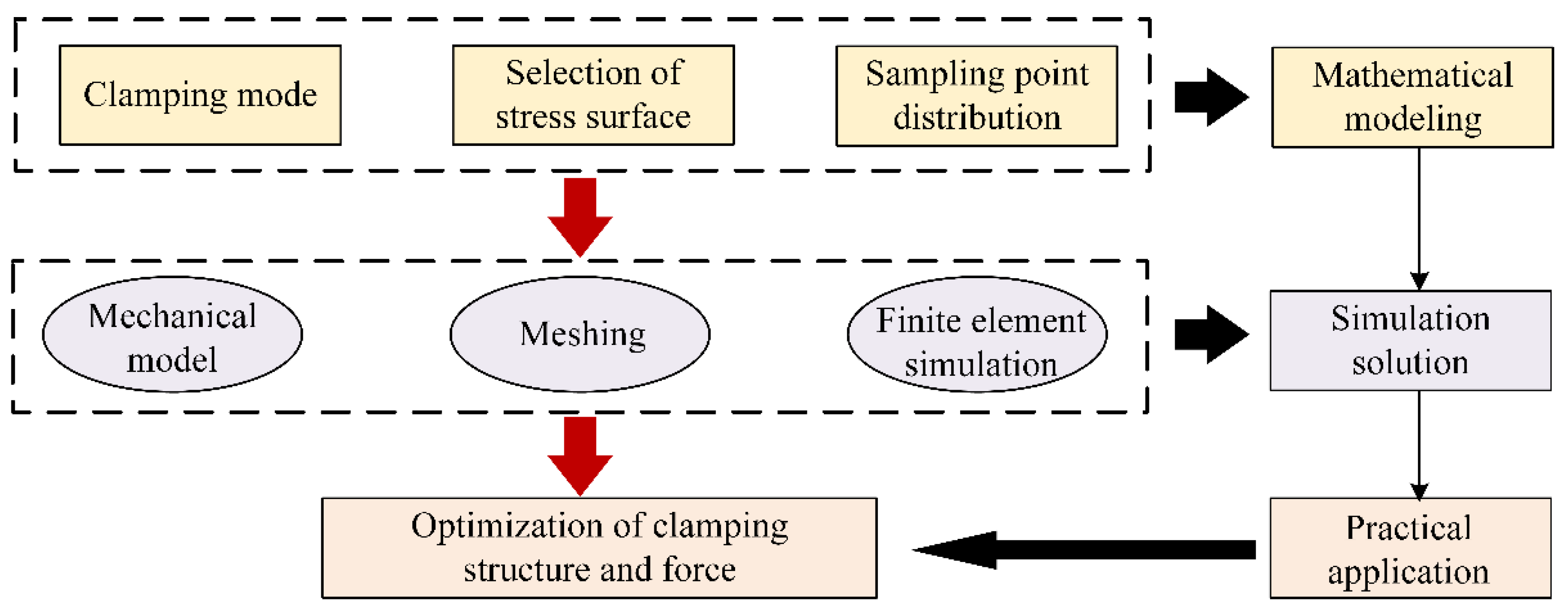
2. Architecture of the RAFD-NM Method

Non-intervention machining (NM) technology is a method implemented in order to reduce the manual intervention in the machining process during manufacturing. It was closely involved with improving product manufacturing efficiency, reducing manual labor intensity, and improving product quality. Accurate fixture, automatic alignment, on-line measurement, and error compensation technology involved are the technical cores of non-intervention processing. In this paper, the technology of RAFD was deeply investigated based on the non-intervention mode, which mainly includes the deformation simulation of fixture, the design of clamping alignment device, and the tooling design scheme for aerospace complex cabin. Firstly, a mechanical model was established. Then, the finite element simulation of the cabin parts was carried out to study the deformation of the parts during the clamping process. Immediately afterwards, the influence of the clamping force on the deformation was analyzed. Then, the off-machine alignment device was designed based on the zero-point positioning system, which realized the accurate movement of the workpiece from one station to another. Finally, depending on the different typical features on the part, different clamping tooling types were designed that adapted the reliable processing of the structure on the outer circle, end face, hole, groove, shell shape, and shell cavity.

3. Simulation of Fixture Deformation

In this section, the research work was carried out with three aspects: establishing a mathematical model for part clamping scheme optimization, finite element simulation of clamping deformation, and clamping optimization. The clamping deformation was predicted for the cabin parts. Then, the optimization design for the clamping scheme was carried out. The overall technical scheme of clamping deformation analysis based on clamping force control is shown in Figure 1.

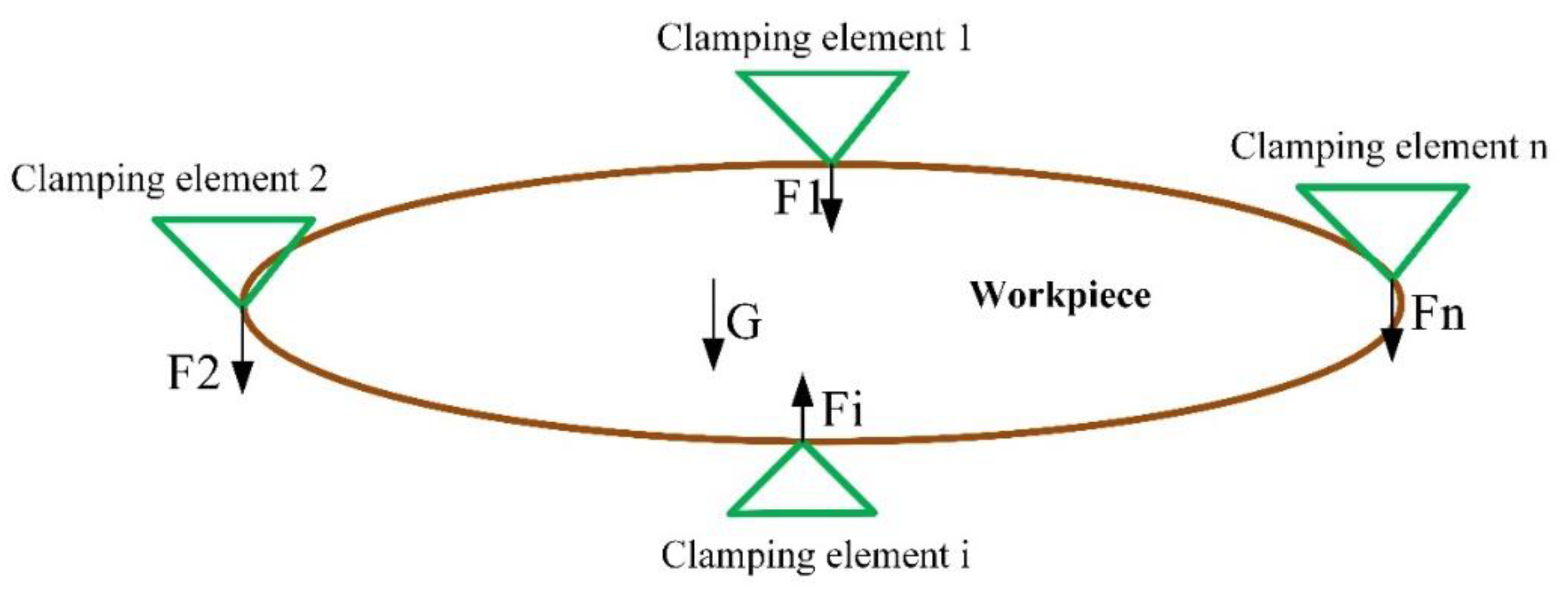
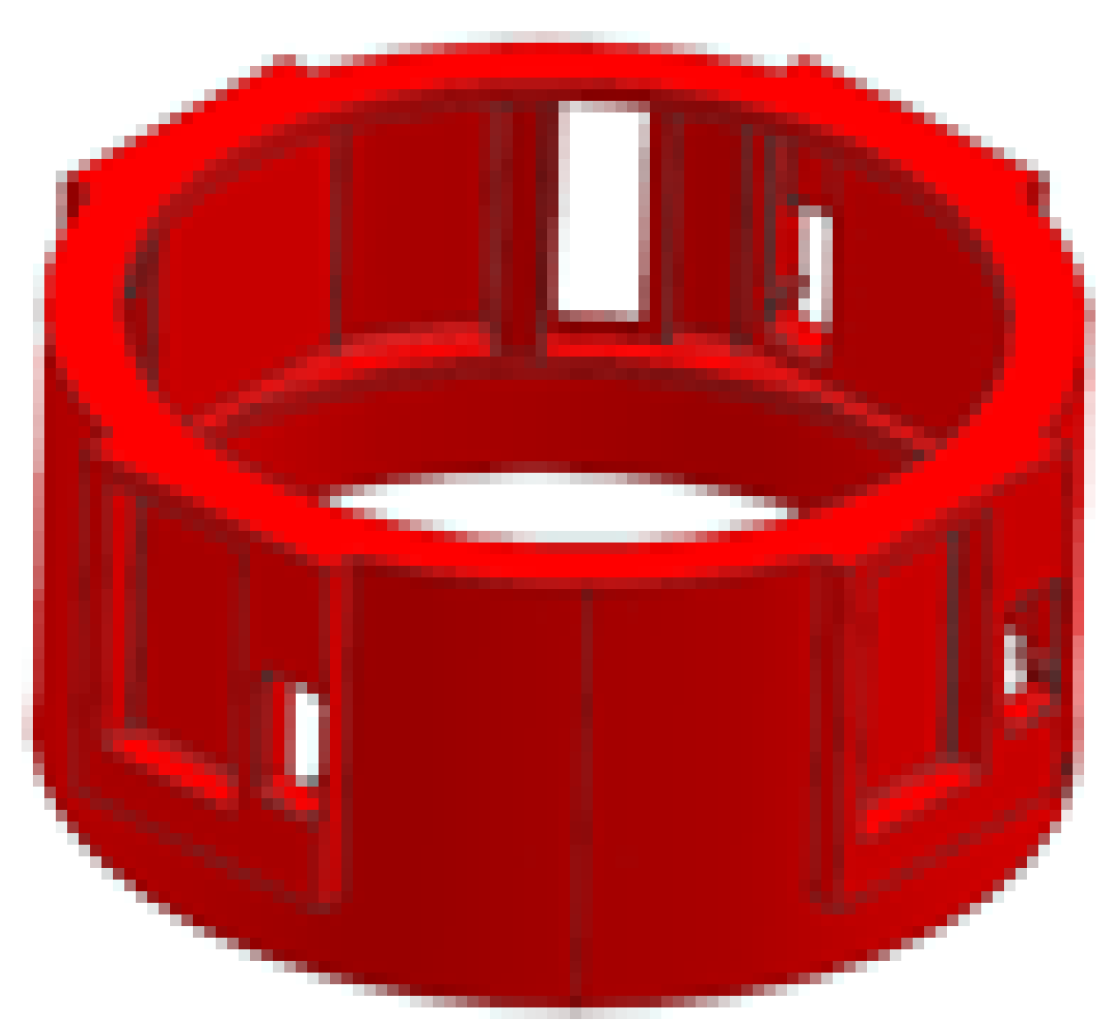
3.1. Clamping Model of Typical Thin-Walled Cabin

In order to ensure the stability of part clamping and weaken the influence of clamping deformation on machining accuracy, a force analysis model of a clamping workpiece was established as shown in Figure 2. F1, F2, Fi and Fn in the Figure 2 were the clamping force exerted by the clamping element on the workpiece, and G was gravity.
Then, the force analysis of typical workpieces was carried out according to the clamping scheme. The optimization of clamping scheme was designed. The optimization goal contains balance constraints, contact constraints, slip constraints, clamping constraints, related constraints, and the shape and position error of the workpiece. Then, the objective function was established according to the optimization objective.
The clamping position, the number of clamping components, the clamping force, and other factors were known as a leading cause of clamping deformation. Therefore, it was necessary to analyze these influencing factors to optimize the clamping plan and control clamping deformation.

3.2. Finite Element Simulation Model of Clamping

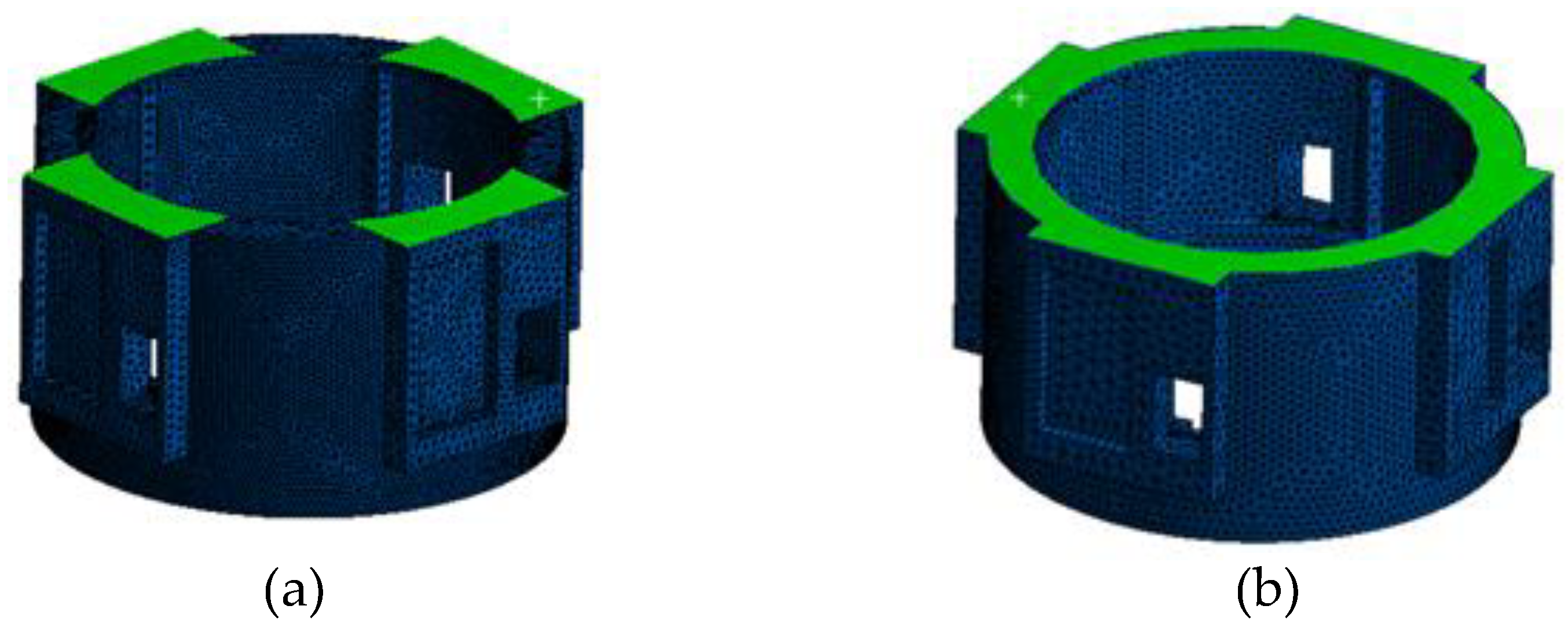
3.2.1. Establishing the Finite Element Model

The finite element analysis model mainly involved the geometric model, material model, and boundary conditions. Based on the commercial finite element analysis software, ANSYS, this paper conducts a simulation prediction of clamping deformation for typical cabin sections.
According to the geometric characteristics of the workpiece, the accuracy of the analysis results and the solution efficiency were considered. The geometric characteristics of non-critical areas were simplified, decreasing the size of the workpiece model. Hence, the calculation time was decreased while ensuring the analysis accuracy. The generation singular points in the process of element division were avoided. The pivotal points of the cabin contact analysis were extracted to divide the structural network reasonably.
The definition of the material model was directly associated with the accuracy of the analysis results. The geometric model after meshing has physical meaning only if its material properties were given. The cabin material investigated in this paper is titanium alloy TA15, the material properties of which at room temperature are shown in Table 1.
As shown in Figure 3, the pressure from the pressing plate was loaded on the corresponding node of workpiece, and all its degrees of freedom was limited. In light of the actual processing requirements, two clamping strategies were formulated as follows: (1) select four stacked areas at top of cabin to press the pressure plate; and (2) press the pressure plate on the whole surface of the top area of the cabin. The loading position is shown in Figure 3.

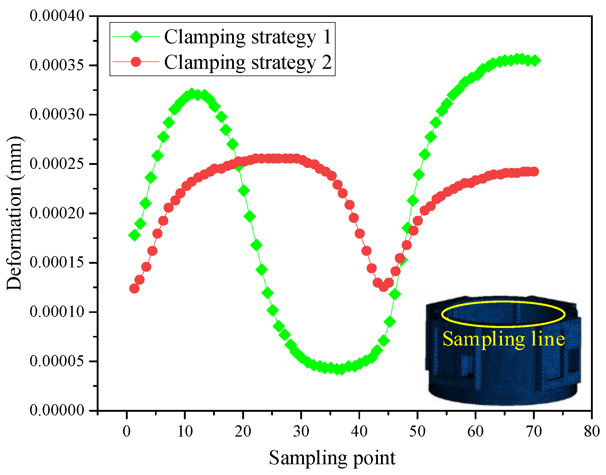
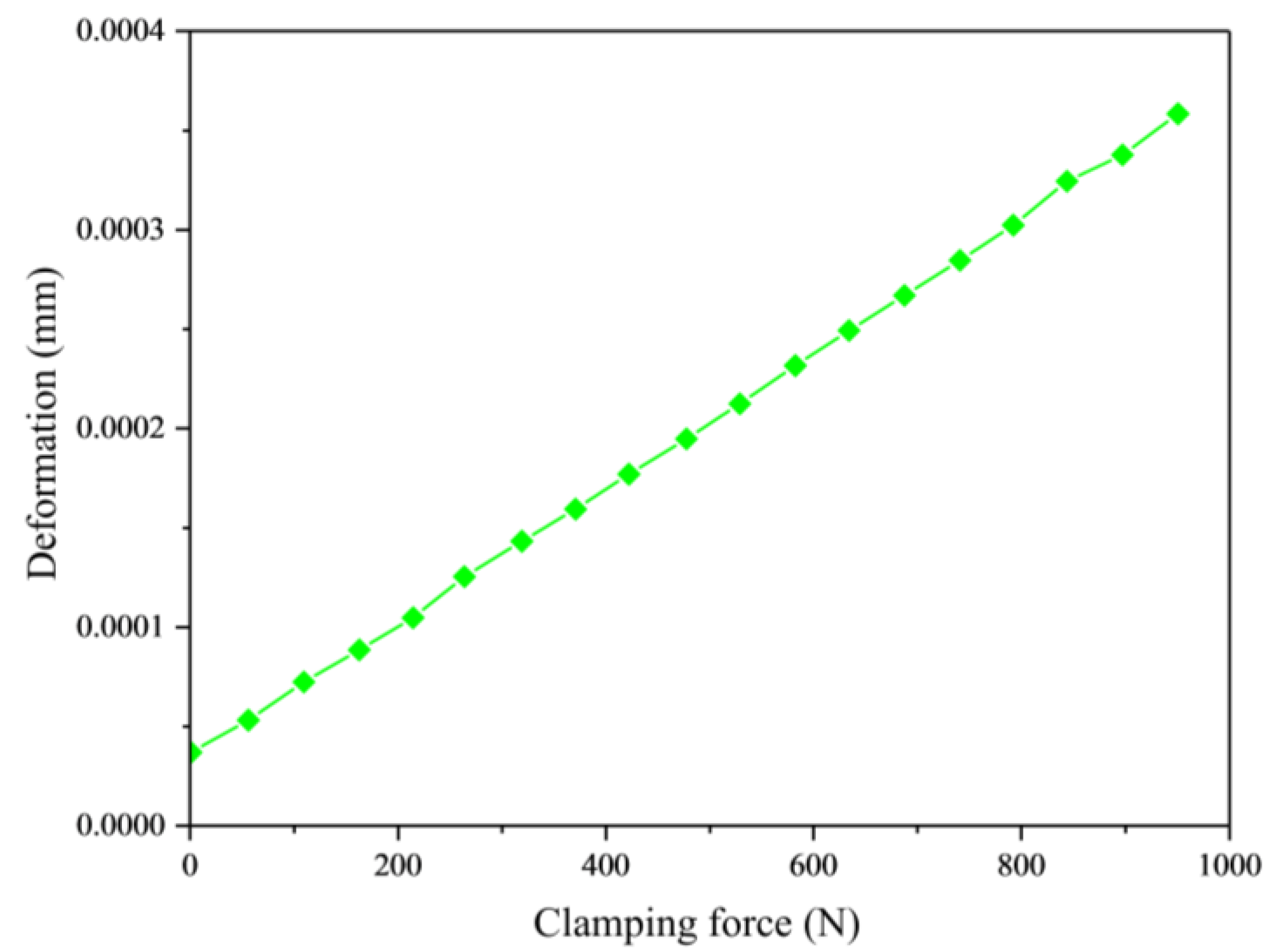
3.2.2. Clamping Deformation Analysis

The clamping force was set to 1000 N, according to the conditions of clamping strategy 1 and clamping strategy 2. The simulation results of the part deformation are shown in Figure 4. The deformation error of the cabin outer circle was considered under the action of the pressure plate. To analyze conveniently, five sampling lines were selected at the cabin outer circle according to different structural characteristics. The deformation of the five sampling lines at the periphery of the selected cabin are shown in Figure 5.
From the deformation simulation results, the following rules can be found: the deformation of each node of the sampling line was small, and the deformation trends of the sampling lines of the two clamping strategies were roughly the same. In the same clamping strategy, the positions of sampling lines 3 and 5 were both located on the reinforcing ribs inside the cabin, for which the deformation laws were same. In addition, compared with clamping strategy 2, the amount of deformation in clamping strategy 1 in sampling lines 2 and 4 greatly increased. In general, the deformation of each sampling line in clamping strategy 1 was greater than that of each sampling line in clamping strategy 2.
On the inner circumference of the upper surface, the sampling curve and simulation results of inner circumference were obtained as shown in Figure 6. It can be seen that the deformation in strategy 1 and strategy 2 was small, and the deformation trend was almost same. Therefore, in order to ensure high-precision machining accuracy, it was more advantageous to use clamping strategy 2. In the actual tooling design, clamping strategy 2 was commonly used for clamping tooling design.
The selection of cabin clamping strategy was completed by the above deformation simulation analysis. Clamping strategy 2 was adopted to control the clamping force. A gradually increasing clamping force was applied to cabin. Then, the trend of the maximum deformation of the cabin was monitored, as shown in Figure 7.
The amount of deformation increased with the increase in clamping force. When the clamping force increased to a certain value, the amount of deformation was close to the maximum allowable error. Therefore, the maximum allowable clamping force was selected by setting the maximum threshold of clamping deformation.
Based on the above mechanical analysis method, the optimal clamping position and clamping force were determined through finite element simulation. This method changes the traditional manner of clamping parts by experience. The special tooling for parts processing was designed on the basis of the analysis results and applied in actual processing.

4. Design of Off-Machine Clamping and Alignment Device

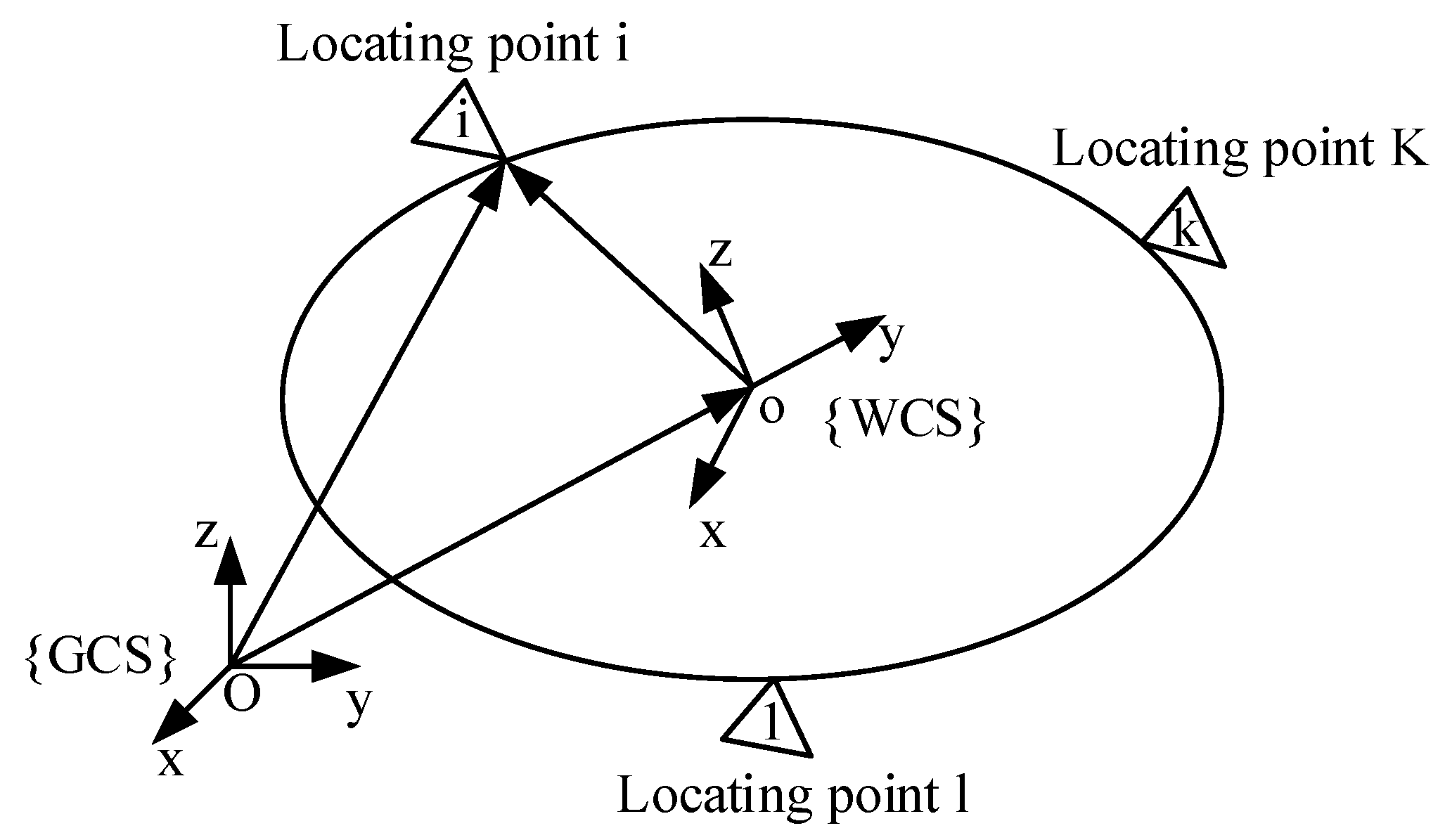
4.1. Principle of Zero-Position System

The principle of the zero-position system was essentially the mapping relationship among the number of specified points, the layout of the positioning points, and the position of the workpiece. The positioning scheme is shown in Figure 8. The global coordinate system was assumed as GCS, and the workpiece coordinate system was a moving coordinate system consolidated on the workpiece (WCS). The workpiece surface was composed of separable smooth surfaces. The point coordinates were converted to the {GCS} coordinate system. Then, the surface equation of the workpiece surface under the coordinate system {GCS} can be obtained. The positioning point was in contact with the workpiece surface when the workpiece was at the theoretical position.

4.2. Principle of Zero-Position System

As shown in Figure 9, the clamping and alignment of the parts were realized using the rapid fixture of the machine tool. The time occupied by the clamping and alignment work on the machine tool was minimized.
The rapid alignment device of the machine tool consisted of a base plate, angular positioning component, end ruler, zero-point positioning system, dial indicator, positioning base upper plate, positioning disc, and pressure plate. The end ruler, angular positioning assembly, and dial indicator were installed on the bottom plate. Where the end ruler was used to drive the upper part to rotate, the angular positioning assembly was used for angular positioning, and the dial indicator was used to detect the roundness during the rotation. The positioning disc was used for the positioning of the end face and the inner circle of the part. The upper plate of the positioning foundation was connected with the part by a pressure plate.
When using this rapid alignment device, the positioning base was used to clamp the parts. Then, alignment with the off-machine rapid clamping device of the machine tool was completed. The exactly same base plate was set on the machine tool, which confirmed the positioning of the upper plate on the machine tool. The specific working principle was as follows. Four ball lock shafts of the zero-position system were installed on the upper plate of the positioning foundation. Four receiving sleeves of the zero-position system were installed on the two bottom plates of the machine tool, which was the platform of the machine tool. A ball-locking bit sleeve was installed at each position, which played the role of positioning and clamping at the same time, when it united with the ball-lock shaft. The other two through holes were matched with the ball-lock shaft as a clearance fit, which only plays a clamping role. The positions of the four ball lock shafts on the base plate were matched with the four receiving sleeves on the base plate one-to-one during use. After the ball lock shaft was inserted and locked, they and the base plate were firmly connected together. Upon completion of the positioning, the repeated positioning accuracy was within ±0.005 mm, which could realize the clamping and rapid positioning of parts.

5. Design of Off-Machine Clamping and Alignment Device

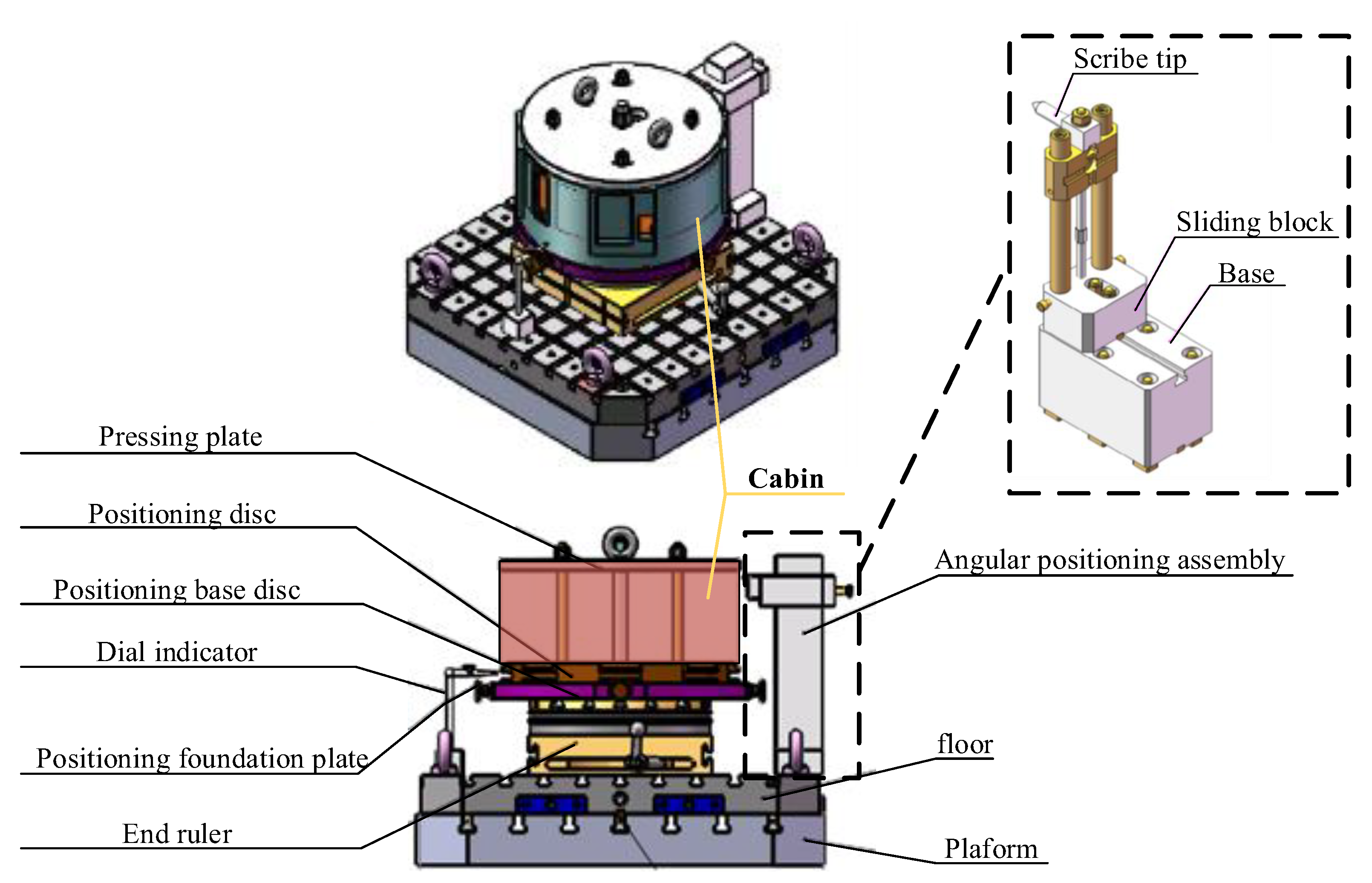
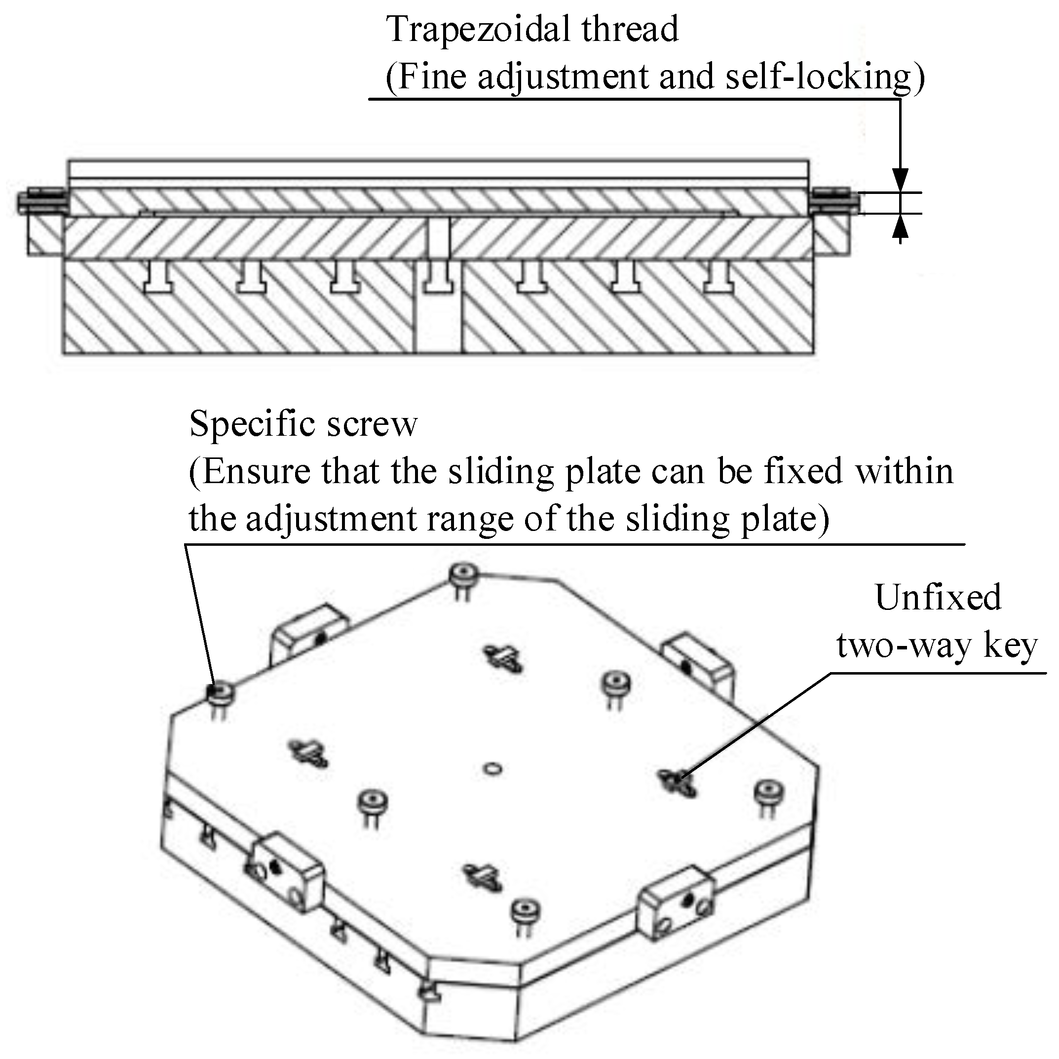
5.1. Design of Rapid Alignment and Adjustment Device for Special-Shaped Cabin Data

The special-shaped cabin parts have many characteristics, including poor rigidity, many processing features, high requirements for technical indicators, and large geometric tolerance. The cabin parts are shown in Figure 10.
This type of cabin was generally processed on a horizontal machining center. It would only be processed when it coincided with the rotation center of the machine tool. When it was necessary to move to other positions to adjust the parts, the parts and the rotation center of the equipment would be moved relative to each other. During the adjustment process, it was easy to cause the parts to be offset and dislocated in the cross direction. The loose pressing plate led to local deformations, which affects the wall thickness. The traditional fixture has the disadvantages of poor machining accuracy control and long clamping adjustment time. After adjustment, repeated alignments were required, which were difficult to operate and took a long time.
According to the design requirements of general clamping tooling for the special-shaped cabin section and the processing characteristics of the special-shaped cabin section, a general process equipment with high efficiency and easy operation was designed. It realized rapid reference adjustment of special-shaped parts on the machining center under the adjustable base plate, as shown in Figure 11.

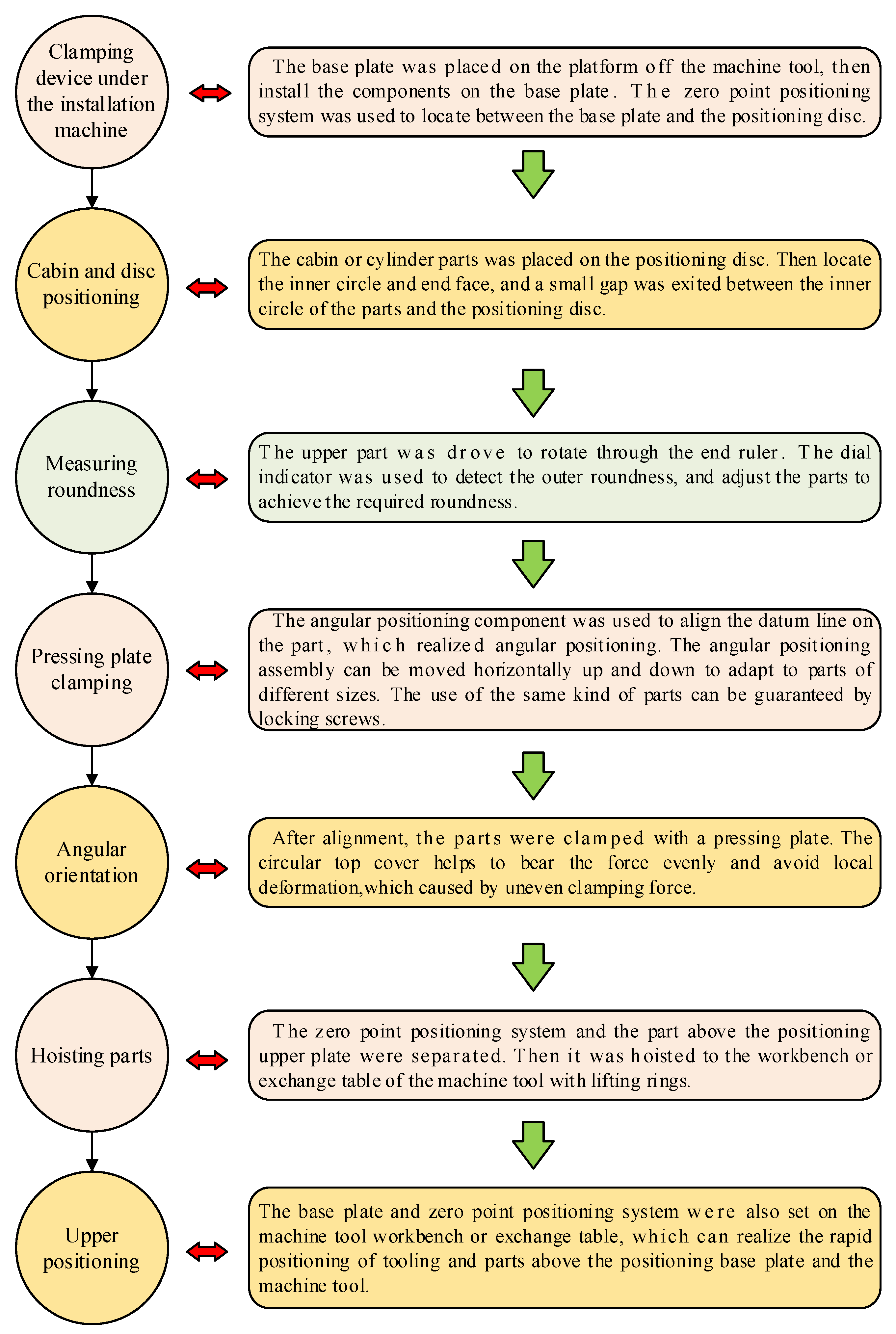
5.2. Operation Flow of Fast Clamping and Alignment on the Off-Machine

At present, the cabin parts experience a problem of long interface size. Meanwhile, the dimensional accuracy of the machining features in the cabin is relatively high. Therefore, the accuracy of machining and clamping alignment were set as higher requirements. The flatness and position accuracy are required to be high, for example, the length of the loaded guide rail in the cabin must be more than 1000 mm. The clamping operation was difficult and the operation time increased, when the parts were clamped many times and were easy to deform. The use of the off-machine rapid clamping and alignment device in this paper can effectively reduce the on-machine clamping time and improve the equipment utilization rate. The implementation scheme is shown in Figure 12.
The off-machine clamping alignment of the cabin section used the ball lock structure of the zero-point positioning system to realize the positioning between the upper plate of the positioning foundation and the positioning disc. The cabin section and the positioning disc were aligned, taking the inner circle and end face of the cabin section as the benchmarks to carry out positioning. Then, we kept the positional relationship among the upper plate of the positioning base, the positioning disc, and the parts of the cabin section unchanged. The end ruler under the positioning upper plate was rotated to drive the cabin section, the positioning disc, and the positioning base plate to rotate. Meanwhile, we aligned the reference line on the parts horizontally or moved the angular positioning assembly up and down to realize the angular positioning of the cabin section under the machine. Finally, we separated the upper part of the positioning upper plate from the bottom plate and moved it to the machine. With the help of the zero-point positioning system, the space position between the cabin section and the machine tool could be realized. The specific operation process is shown in Figure 13.

6. Conclusions

This paper proposes a new clamping tooling design method based on non-intervention processing. It provides a reference for the design method and specific implementation scheme of clamping tooling for such parts. The main conclusions of this paper are as follows:
  • A rapid and accurate fixture tooling design method was proposed based on non-intervention processing mode. It includes clamping simulation analysis of clamping deformation, the design of a off-machine clamping alignment device, and a tooling design method suitable for rapid and accurate fixture of an aerospace complex cabin.
  • After analyzing the simulation results of commercial software, it is found that the clamping method of integral surface pressing plate is more conducive to decrease deformation. Furthermore, the deformation increased with the increase in clamping force. It approached the maximum allowable error when the clamping force increased to a certain value.
  • The proposed methods were implemented in a case. The rapid clamping positioning and accurate clamping for tooling and parts in non-intervention processing mode were realized, which using our designed off-machine alignment device. This method lays a foundation for the construction and application of a flexible processing production line.

Author Contributions

Conceptualization, G.D. and S.Y.; Methodology, Y.W.; Validation, L.L.; Writing—original draft, Y.W.; Writing—review & editing, G.D. and Z.Z. All authors have read and agreed to the published version of the manuscript.

Funding

This research received no external funding.

Institutional Review Board Statement

Not applicable.

Informed Consent Statement

Not applicable.

Data Availability Statement

Not applicable.

Conflicts of Interest

The authors declare no conflict of interest.

References

  1. Ma, J.; Li, Y.; Zhang, D.; Zhao, B.; Wang, G.; Pang, X. Dynamic response prediction model of thin-wall workpiece-fixture system with magnetorheological damping in milling. J. Mater. Process. 2022, 74, 500–510. [Google Scholar] [CrossRef]
  2. Wu, D.; Wang, H.; Huang, L.; Wang, Y. Computer aided machining fixture design algorithm and software based on case learning for near-net-shaped jet engine blade. J. Mater. Process. 2021, 69, 545–555. [Google Scholar] [CrossRef]
  3. Zhou, Y.; Li, Y.; Wang, W. A feature-based fixture design methodology for the manufacturing of aircraft structural parts. Robot. Comput. Integr. Manuf. 2011, 27, 986–993. [Google Scholar] [CrossRef]
  4. Olaiz, E.; Zulaika, J.; Veiga, F.; Puerto, M.; Gorrotxategi, A. Adaptive Fixturing System for the Smart and Flexible Positioning of Large Volume Workpieces in the Wind-Power Sector. Procedia CIRP 2014, 21, 183–188. [Google Scholar] [CrossRef] [Green Version]
  5. Bakker, O.J.; Papastathis, T.N.; Popov, A.A.; Ratchev, S.M. Active fixturing: Literature review and future research directions. Int. J. Prod. Res. 2013, 51, 3171–3190. [Google Scholar] [CrossRef] [Green Version]
  6. Parvaz, H.; Nategh, M.J. Development of locating system design module for freeform workpieces in computer-aided fixture design platform. Comput. Aided Des. 2018, 104, 1–14. [Google Scholar] [CrossRef]
  7. Croppi, L.; Grossi, N.; Scippa, A.; Campatelli, G. Fixture Optimization in Turning Thin-Wall Components. Machines 2019, 7, 68. [Google Scholar] [CrossRef] [Green Version]
  8. Bowden, D.M.; Halley, J.E. Aluminium Reliability Improvement Program-Final Report 60606; The Boeing Company: Chicago, IL, USA, 2001. [Google Scholar]
  9. Salgado, M.A.; de Lacalle, L.N.L.; Lamikiz, A.; Muñoa, J.; Sánchez, J.A. Evaluation of the stiffness chain on the deflection of end-mills under cutting forces. Int. J. Mach. Tool. Manuf. 2005, 45, 727–739. [Google Scholar] [CrossRef]
  10. Xiong, L.; Molfino, R.; Zoppi, M. Fixture layout optimization for flexible aerospace parts based on self-reconfigurable swarm intelligent fixture system. Int. J. Adv. Manuf. Technol. 2013, 66, 1305–1313. [Google Scholar] [CrossRef]
  11. Li, Y.; Liu, C.; Hao, X.; Gao, J.X.; Maropoulos, P.G. Responsive fixture design using dynamic product inspection and monitoring technologies for the precision machining of large-scale aerospace parts. CIRP Ann. Manuf. Technol. 2015, 64, 173–176. [Google Scholar] [CrossRef]
  12. Qi, R.; Mao, X.; Zhang, K.; Xia, R. Accurate Clamping Method of Multipoint Flexible Fixture for Large Complex Surface. Math. Probl. Eng. 2021, 2021, 1–10. [Google Scholar] [CrossRef]
  13. Aurrekoetxea, M.; de Lacalle, L.N.L.; Llanos, I. Machining Stresses and Initial Geometry on Bulk Residual Stresses Characterization by On-Machine Layer Removal. Materials 2020, 13, 1445. [Google Scholar] [CrossRef] [PubMed] [Green Version]
  14. Michael Thomas Rex, F.; Hariharasakthisudhan, P.; Andrews, A.; Abraham, B.P. Optimization of flexible fixture layout to improve form quality using parametric finite element model and mixed discrete-integer genetic algorithm. P. I. Mech. Eng. C J. MEC. 2022, 236, 16–29. [Google Scholar] [CrossRef]
  15. Ma, J.; Zhang, D.; Wu, B.; Luo, M.; Chen, B. Vibration suppression of thin-walled workpiece machining considering external damping properties based on magnetorheological fluids flexible fixture. Chin. J. Aeronaut. 2016, 29, 1074–1083. [Google Scholar] [CrossRef] [Green Version]
  16. Wang, T.; Zha, J.; Jia, Q.; Chen, Y. Application of low-melting alloy in the fixture for machining aeronautical thin-walled component. Int. J. Adv. Manuf. Technol. 2016, 87, 2797–2807. [Google Scholar] [CrossRef]
  17. Wang, X.; Ma, P.; Peng, X.; Ning, S. Study on vibration suppression performance of a flexible fixture for a thin-walled casing. Int. J. Adv. Manuf. Technol. 2020, 106, 4281–4291. [Google Scholar] [CrossRef]
  18. Huamin, W.; Guohua, Q.; Zhuxi, W.; Dunwen, Z. A workpiece stability-based iterative planning of clamping forces for fixturing layout specification of a complex workpiece. Int. J. Adv. Manuf. Technol. 2019, 103, 2017–2035. [Google Scholar] [CrossRef]
  19. Wu, D.; Wang, H.; Peng, J.; Zhang, K.; Yu, J.; Zhengg, X.; Chen, Y. Machining fixture for adaptive CNC machining process of near-net-shaped jet engine blade. Chin. J. Aeronaut. 2020, 33, 1311–1328. [Google Scholar] [CrossRef]
  20. Wang, Y.; Xie, J.; Wang, Z.; Gindy, N. A parametric FEA system for fixturing of thin-walled cylindrical components. J. Mater. Process. Technol. 2008, 205, 338–346. [Google Scholar] [CrossRef]
  21. Wang, Z.; Li, C.; Yang, B.; Yang, Y. Fixture Locating Layout Optimization of Curved Thin-walled Parts Based on FDA. Chin. J. Mech. Eng. 2017, 28, 2231–2236. [Google Scholar]
  22. Su, J.; Cai, Y.; Jiang, X.; Qiang, Y.; Wang, Y.; Liu, X. Modeling of stiffness characteristic on evaluating clamping scheme of milling of thin-walled parts. Int. J. Adv. Manuf. Technol. 2021, 113, 1861–1872. [Google Scholar] [CrossRef]
Figure 1. Overall scheme of clamping deformation analysis technology based on clamping force control.
Metals 12 01174 g001
Figure 2. Workpiece clamping force model.
Metals 12 01174 g002
Figure 3. Loading position of different clamping strategies. (a) Loading position of clamping strategy 1; (b) loading position of clamping strategy 2.
Metals 12 01174 g003
Figure 4. Clamping deformation of cabin section under different clamping strategies. (a) Clamping strategy 1; (b) clamping strategy 2.
Metals 12 01174 g004
Figure 5. Deformation of each sampling line. (a) Deformation of each sampling line in clamping strategy 1; (b) deformation of each sampling line in clamping strategy 2.
Metals 12 01174 g005
Figure 6. Deformation of inner circumference sampling line.
Metals 12 01174 g006
Figure 7. Relationship between clamping force and deformation.
Metals 12 01174 g007
Figure 8. Location model.
Metals 12 01174 g008
Figure 9. Rapid alignment device on off-machine.
Metals 12 01174 g009
Figure 10. The three-dimensional structure of cabin parts.
Metals 12 01174 g010
Figure 11. Adjustable base plate.
Metals 12 01174 g011
Figure 12. Implementation scheme diagram of rapid clamping and alignment of the machine for complex cabin section.
Metals 12 01174 g012
Figure 13. Clamping and alignment operation flow chart.
Metals 12 01174 g013
Table 1. TA15 material properties.
Elastic Modulus (GPa)Poisson’s RatioDensity (kg·m−3)Yield Strength (MPa)Tensile Strength (MPa)
1180.3344501000700
Publisher’s Note: MDPI stays neutral with regard to jurisdictional claims in published maps and institutional affiliations.

