Abstract
The objective of this study was to improve the corrosion resistance of an A535 alloy by removing intermetallics on the alloy surface by alkaline etching to improve the morphologies and properties of the anodic film that was sealed with different sealants. It was found that alkaline etching for 4 min was suitable for dissolving intermetallic particles and simultaneously providing sufficient roughness for the adhesion of an oxide film to the Al matrix. The effect of alkaline etching revealed that a decrease in the intermetallic fraction from 21% to 16% after etching for 2 and 4 min, respectively, corresponded to the increase in the surface roughness, thickness, and consistency of the anodic film. It was also demonstrated that the surface morphology of the anodic films after stearic acid sealing was more uniform and compact than that after nickel fluoride sealing. The electrochemical polarization curves and salt spray test proved that the alloy etched for 4 min and sealed with stearic acid had better corrosion resistance as compared with the aluminum alloy sealed with nickel fluoride.
1. Introduction
A535 aluminum–magnesium casting alloy is widely used in marine and other corrosive-prone applications due to excellent resistance to corrosion in seawater, and heat treatment and natural aging are not required to reach maximum properties [1,2]. Moreover, aluminum casting alloys have clear economic advantages over wrought alloys, such as mass production of net-shape components and no requirement for homogenization [3]. However, the critical problem of corrosion resistance in Al–Mg cast alloys with more than 3 wt.% Mg is a number of intermetallic phases, which makes it challenging to enhance corrosion resistance by the anodizing process. Furthermore, these alloys have increased susceptibility to corrosion [4,5], which relates to the precipitation of Mg-rich intermetallic compound (IMC) particles at grain boundaries and the free sample surface [6,7], affecting the stress corrosion cracking [8,9] and the properties of oxide films [10]. Previous work investigated the corrosion behavior of an Al–Mg alloy (5A06) and found that the Si containing intermetallics were embedded in the anodic film surface [11]. It was also reported that the active Al3Mg2 intermetallic with a lower corrosion potential of about −1.29 V vs. the saturated calomel electrode (SCE), as compared with −0.73 V vs. SCE for the matrix, led to the increased anodic activity in the corrosive environment [5].
Anodizing is an electrochemical finishing process, forming porous anodic oxide films consisting of an inner block layer and an outer porous layer, which significantly improves corrosion resistance of the alloys [3]. It is commonly used to improve corrosion resistance of aluminum alloys for military and seawater applications [12]. The application of anodizing to cast alloys (that provides the corrosion resistance without homogenization treatment) is considered to be more challenging than for wrought aluminum alloys because of the formation of Al–Mg and Al–Mg–Mn IMCs embedded in the aluminum matrix, which prevents the formation of a uniform anodic film [12]. It was also reported that anodizing often resulted in defects around IMC particles [13,14]. As a result, painting is commonly used instead of anodizing to increase the corrosion resistance of cast products. However, in this way, the corrosion resistance of aluminum castings is lower than that obtained by anodizing because anodic films are usually much stronger and better adherent as compared to paint and metal plating [15,16]. Thus, a better understanding of the anodization on aluminum castings is necessary to overcome this drawback.
Surface pretreatments can play a significant role in enhancing the corrosion protection performance through controlling an appropriate surface roughness, which can result in stronger adhesion between the anodic film and the aluminum substrate [17]. Moreover, mechanical polishing and electropolishing can reduce surface roughness, assuring the surface quality for high quality anodic oxide film [18,19]. On the other hand, the formation of a porous structure on the surface can be due to the removal of intermetallics from the matrix by surface treatment [11]. Therefore, the anodic oxide films are heterogeneous, and corrosion resistance can be adversely affected. To obtain a consistent oxide film with good properties, surface pretreatment must be carefully selected. Different techniques to clean the natural surface oxides and to reduce the number of intermetallic compounds on the surface have been suggested [20]. Sealing treatment is a chemical process to reduce the porosity of oxide layers and improve the corrosion resistance of aluminum alloys [21,22]. In the case of nickel fluoride cold sealing, the pores are filled with aluminum hydroxide, aluminum fluoride, and nickel hydroxide on the top of the anodic oxide at low temperature [23,24]. However, the use of nickel or fluoride anions should be avoided due to health and safety regulations and the management of the wastewater treatment. Therefore, the use of green, non-toxic acids, such as long-chain organic stearic and isosteric acids, to seal the anodic oxide layer of anodized aluminum alloys have been developed [25,26]. Recent work reported that the mixed sealing using modified nickel fluoride in cold sealing decreased the corrosion current density, which enhanced the corrosion resistance of an anodized aluminum alloy [27]. In our previous work, we found that the corrosion resistance of an A535 alloy can be improved using stearic sealing [28]. However, such aluminum alloys contain high content of magnesium, silicon, and copper as alloying elements, which form intermetallics that impede anodizing and sealing [29,30]. Thus, there is a need for surface treatment that can remove intermetallics on the surface.
Thus, this research aims to study the effect of intermetallic removal by alkaline etching in a pretreatment process on the anodic oxide layer and to compare the effects of nickel fluoride and steric acid sealing on the properties of the anodic oxide layer and, eventually, on the corrosion resistance of an anodized A535 alloy. The alloy was anodized in a sulfuric–oxalic mixed acid modified with aluminum sulfate addition as a corrosion inhibitor and sealed in nickel fluoride or stearic acid. Morphologies of the etched surface and anodic oxide films were observed by scanning electron microscopy (SEM). Anodic oxide film hardness tests were conducted using a micro-Vickers hardness tester. Salt spray and electrochemical tests were used to characterize the corrosion resistance of the oxide film with respect to the alkaline etching and sealing treatment.
2. Materials and Methods
2.1. Materials
An AlMag35 or A535 aluminum-magnesium casting alloy was used in this study. The experimental alloy was prepared in a silicon carbide crucible in an induction furnace at a temperature of 750 °C from 99.9 wt.% pure Al, 99.5 wt.% pure Mg, 100 wt.% pure crystal Si, Al-20 wt.% Mn, Al-10 wt.% Ti, and Al-20 wt.% Fe master alloys. To minimize gas porosity and clean the liquid metal of entrained oxides, argon bubble technique and cover fluxes were used to trap the oxides in the molten alloy dross, which was removed before casting. Next, the alloy melt was poured into a cylindrical copper mold (30 mm diameter, 40 mm height), which permitted a uniform cooling rate. The pouring temperature was kept at 650 °C. The chemical composition of the alloy was inspected using an optical emission spectrometer (OES), and the results are shown in Table 1. Microstructure of the as-cast alloy was observed by optical microscope (Zeiss model Axiolab 5).

Table 1.
Chemical composition of an A535 Al-Mg casting alloy (wt.%).
2.2. Surface Preparation
The cast cylinder was cut into several discs. Each disc had dimensions of 30 mm diameter and 5 mm thickness. The discs were used as samples in this study. Surfaces of each disc were mechanically–chemically treated as follows. First, samples were polished with silicon carbide (SiC) abrasive papers of decreasing granulometry. Next, the microstructure was observed in the center of the specimen to avoid a chill zone effect using an optical microscope. Subsequently, the specimens were etched (alkaline etching) by immersion in sodium hydroxide 5% weight by volume in aqueous solution at 45–50 °C with various durations of the etching from 1 to 4 min before desmutting by immersion in 25 vol.% nitric acid for 2 min and DI water for 30 s.
The samples were cleaned with DI water in order to determine effects of alkaline etching on the anodic oxide film. An average surface roughness (Ra) of the samples was determined by a surface roughness tester (Taly Surf Series 2, Taylor-Hobson, Leicester, England). Five measurements of Ra were obtained for each sample to reflect the amount of intermetallic compound remaining at the surface after alkaline pretreatment. The area fraction of intermetallic on the surface after alkaline etching was also determined by image analysis (ImageJ software 1.53k, Wayne Rasband and contributors, National Institutes of Health, Bethesda, MD, USA).
2.3. Anodizing and Sealing Treatment
Individual samples were anodized in a mixed electrolyte of 175 g/L sulfuric acid, 0.16 mol/l aluminum sulfate, and 30 g/L of oxalic acid. Temperature of the solution was controlled in the range of 18–20 °C, using a constant current density of 0.1 A/cm2 with potential ranges of 15 to 20 voltage for 30 min. Temperature of the solutions was maintained by a bath chiller with a temperature controller. The current was served by a direct current (DC) stabilized power supply (PSP-603, Good will instrument, New Taipei city, Taiwan), and a pure aluminum electrode was used as a cathode. After anodizing, all samples were sealed, rinsed in ethyl alcohol, and dried in warm air. The anodized samples were sealed with two different sealants: nickel fluoride (cold sealing) and stearic acid (hydrothermal sealing). The processing parameters of the sealing treatment are shown in Table 2. Table 3 shows the list of the experiment conditions for this investigation.
Table 2.
Process parameters of sealing techniques applied to anodic oxide films (based on ref. [22]).
Table 3.
Notations of samples with different pretreatments and sealing methods.
2.4. Characterization of Anodic Oxide Films
The surface morphology of the anodic oxide films after sealing was examined with a scanning electron microscope (SEM, JSM-6610 LV, JEOL, Tokyo, Japan). The samples were coated with a 1-nm thick layer of gold to reduce the charging effect on the surface and thus to improve the image quality. The area fraction of voids on the anodic oxide films were examined by SEM micrograph and quantified with ImageJ software using three positions on three independent images.
The average thickness of the anodic oxide film was measured according to ASTM B487 by using cross-section SEM micrographs.
X-ray diffraction patterns of both oxide deposited films were investigated at room temperature using a Rigaku model smartlab operating with CuKα radiation (1.541874 Å). The intensities were recorded within 2θ from 10 to 90 at a step size of 12 degree/min with current 30 mA and voltage 40 kV.
2.5. Vickers Microhardness
Measurement of microhardness was performed under a load of 300 g for 15 s using a Vickers microhardness tester (FM-700e, FUTURE-TECH, Tokyo, Japan). The microhardness was measured at five points for each specimen, and the mean value of these measurements was accepted as the microhardness value of the anodic film.
2.6. Corrosion Testing
A salt spray test was performed to investigate the appearance of corrosion products on the surface after exposure to a corrosive environment. It was conducted according to ASTM B117. A solution of 5 wt.% NaCl was sprayed during 336 h on the specimens in a closed chamber (PT2070, PERFECT, Taipei, Taiwan) with temperature maintained at 37 °C. The appearance of corroded samples was assessed through macro- and microstructure by OM and SEM.
Electrochemical corrosion tests were performed in a 5 wt.% NaCl aqueous solution at room temperature in a three-electrode system using Potentiostat–Galvanostat model Autolab P302N. The specimen was treated as a working electrode with an evaluated area of 1 cm2, a platinum wire was used as a counter electrode, and a saturated calomel was used as a reference electrode. The specimens were exposed in the electrolyte until the reaction reached a stable open circuit potential (OCP) value before the electrochemical tests. The measurements were done at a scan rate of 0.033 V/s. To ensure the repeatability of the measurements, the test was done on three replicates.
The polarization curves were recorded with an Auto lab potentiostat, and the corrosion current density (Icorr) data were determined at the intersection of rectilinear sections of the anode and cathode from a Tafel plot by extrapolating the linear portion of the curve to ECORR using Nova Autolab software (version 1.11.2, Metrohm, Herisau, Switzerland). However, we use adjacent averaging method, which takes the average of a user-specified number of data points around each point in the data, and replaces that point with the new average value to smooth the data before fitting the slope for calculation of the polarization parameters as well as the current density (Icorr).
3. Results and Discussion
3.1. Surface Pretreatment Characterization
Figure 1 shows the microstructure of an as-cast A535 alloy comprising dendrites of the aluminum solid solution and eutectic Al3Mg2 IMC at the grain boundaries. These intermetallics are formed at the boundaries of Al dendrites as a divorced eutectic in alloys containing above 3 wt.% Mg and may lead to the corrosion of the alloy [7]. Some other intermetallics formed by Mn, Fe, and Si (e.g., Mg2Si) are also formed but are present in much less quantity.

Figure 1.
Microstructure of an as-cast A535 alloy, optical microscopy.
Figure 2 shows the relationship between the average roughness (Ra) and duration of etching time. An average roughness of the samples increased from 0.098 ± 0.025 μm at the beginning of etching to 0.744 ± 0.021 μm after 5 min of etching due to the surface chemical attack. This agrees well with previously reported increases in roughness with the etching time due to dissolution of Si on the surface of Al–Si alloys [31].

Figure 2.
Average roughness Ra of an A535 alloy after mechanical polishing and alkaline etching.
Figure 3a,c show the surface of the specimens that had been alkaline etched for 2 and 4 min, respectively. One can see a typical porosity with irregular pore shape on the surface after etching for 2 min due to the chemical attack onto the Al matrix (Figure 3a). The dissolution of the surface was relatively uniform, as demonstrated in Figure 3b. After 4 min alkaline etching, round-shaped pores appeared in addition to irregular grain boundary pores (Figure 3c). At this stage, the surface acquired pronounced roughness, as revealed by cross-sectional characterization in Figure 3d, caused by the slower dissolution of the intermetallic particles as compared to that of the Al matrix. This resulted in the formation of trench or IMC groove shapes due to the preferential dissolution of the Al matrix at the periphery of IMC particles during etching and desmutting. Consequently, the particles fell off the matrix, resulting in the scallops, which subsequently expanded to larger pores as etching continued. With increased etching time, the diameter of pores significantly increased due to the higher reactivity of the aluminum matrix with the alkaline solution [32]. Similar observations were reported for the behavior of Mg2Si particles in an AA5052 alloy [33]. Based on these results, we selected alkaline etching pretreatments of 2 and 4 min to investigate the formation and properties of the oxide film. The result showed that the decrease in the percentage of the fraction of IMC after being alkaline etched for 4 min, which corresponded to previous research [34].
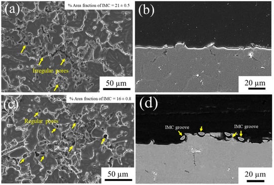
Figure 3.
SEM micrographs of the A535 substrate surface (a,c) and cross-section surface (b,d) after alkaline etching for (a,b) 2 min and (c,d) 4 min.
3.2. Characterization of Anodic Oxide Film on a Cast A535 Alloy
3.2.1. Surface Morphology of Anodic Oxide Films
SEM micrographs of the anodic oxide film surface are shown in Figure 4. The anodic oxide film of unsealed samples 2-A and 4-A demonstrates the remains of IMC on the surface, and the oxide film appears to be discontinuous. After just 2 min of anodizing, there are still clearly visible IMC with retained morphology (Figure 4a), whereas after 4-min anodizing, the IMC are largely dissolved with only voids and grooves remaining (Figure 4d). This can be explained by the removal of particles by prolonged alkaline etching.
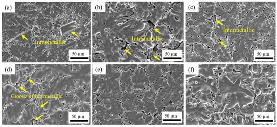
Figure 4.
Surface micrographs of anodic oxide films with different pretreatment and sealing methods: (a) 2-A, (b) 2-N, (c) 2-S, (d) 4-A, (e) 4-N, and (f) 4-S (SEM).
When the particles remain on the surface, the voids cannot be sealed completely either by NiF2 or stearic acid (Figure 4b,c). However, when the intermetallics fall off during longer etching, these voids can be covered by sealants, which results in the anodic oxide film being more uniform, as demonstrated in Figure 4e,f. Apparently, the intermetallics inhibit the oxide film growth, as evidenced by the EDS element mapping of oxide film surface in Figure 5 that shows that the layer of oxide is discontinuous. This confirms the harmful role of intermetallics in the formation of a uniform oxide film and the necessity of a proper pretreatment time, as reported previously for other Al–Mg–Si alloys [35].
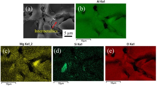
Figure 5.
EDS element mapping of the oxide film surface in the sample etched for 2 min: (a) SEM image, and EDS mapping elements: (b) Al, (c) Mg, (d) Si, and (e) O.
These observations are confirmed by the quantitative analysis of void area fraction on the surface in Figure 6. Sample 4-A etched for 4 min shows a larger portion of voids on the surface due to the removal of IMC; the area fraction is 4.48%. After sealing, the area fraction of pores decreases significantly, especially after sealing with stearic acid (specimen 4-S), when it comes down to 4.25%. The area fraction of pores is as low as the plasma electrolytic oxidation coating that formed on the surface of the Al–Mg–Si alloy [36]. The nature of these voids is related to the formation of grooves in place of intermetallics on the surface as a result of alkaline etching. Longer etching produces more voids and also accelerates the growth of the anodic oxide film [35]. The results also show that the alloy etched for 4 min and sealed with nickel fluoride still has more voids left on the surface as compared to the stearic acid sealant. This may be caused by the formation of Ni (OH)2 during the chemical reaction. Ni(OH)2 deposit is formed due to hydrolysis of Ni2+ ions, with alumina mainly converted to aluminum hydroxide and F− ions reacting with alumina and AlF3 [37]. These products form within the pores of anodic films and block the pores, as can be seen in the element mapping of oxygen and nickel in the particles on the oxide film in the inset in Figure 7a. Therefore, nickel fluoride cannot penetrate the pores beneath the substrate, which causes incomplete coverage of the surface. Stearic acid does not have these byproducts, as the stearic solution can react with the aluminum hydroxide of sealed anodic layers to transform a layer of long chain fatty soap film with alumina by chemical reaction. It was reported that these films have strong hydrophobic properties [24], as we can see from the sealing film between voids in our results. Consequently, the voids of anodic film layer were sealed entirely, as shown in Figure 7b,c.

Figure 6.
Area fraction of voids on anodic oxide films with different pretreatment and sealing methods.

Figure 7.
SEM micrograph of the oxide film with sealants showing byproducts and sealing film after sealing with (a) nickel fluoride with element mapping of O and Ni in the inset, and (b) stearic acid with (c) high magnification of sealing film in the voids.
Figure 8 shows the surface morphology of unsealed and sealed anodic oxide layers. The anodizing process without sealing induces an uneven oxide layer without a superficial film, as can be seen in Figure 8a,d. After sealing in nickel fluoride solution or stearic acid, the surface is covered by a sealing film. In the specific case of nickel fluoride sealing, as can be seen in Figure 8b,e, the sealing surface is uniform, and the morphology of this overlayer looks like a hydroxide sheet that is formed by the conversion of porous alumina into Al(OH)3 and Ni(OH)2 that was also deposited on the oxide film surface, similar to that reported elsewhere [27,38]. These oxides were investigated and confirmed by XRD results. Figure 8g shows the XRD spectra of the sample 4-N; the XRD profile reveals that the peaks of Al(OH)3 and Ni(OH)2 were detected.

Figure 8.
Magnified images of the anodized sample surface with each alkaline etching for (a–c) 2 min and (d–f) 4 min: (a,d) without sealing; (b,e) sealed with nickel fluoride and (c,f) sealed with stearic acid (SEM); and (g) XRD result of Al(OH)3 and Ni(OH)2 oxides of 4-N specimen.
On the other hand, the sample sealed with stearic acid exhibits layers of rose petal-shaped formations covering the entire surface, as can be seen in Figure 8c,f. These formations represent the inorganic salt of Al(OH)3 occurring during the sealing reaction when liquid acid spreads onto the surface [39]. These formations in Al–Si and some other alloys have been reported before [27] and are known to be indicative of a Cassie impregnating wetting regime when the liquid, but not the wetting the surface, remains on it due to the special interaction with the surface roughness. Such surfaces are expected to exhibit high adhesive bond strength between the substrate and the oxide film [40].
3.2.2. Thickness and Hardness of the Anodic Oxide Film on an A535 Alloy
Figure 9 demonstrates cross-sections of anodic oxide films without the sealing process after etching for 2 and 4 min (Figure 9a,d) in alkaline solution and after sealing with NiF2 (Figure 9b,e) and stearic acid ((Figure 9c,f). It can be observed that the oxide films without sealing show non-uniform growth disturbed by intermetallics while exhibiting flaws and voids on the surface of oxide films: the more, the longer the etching is, as indicated in Figure 9a,d.

Figure 9.
Cross-section micrographs of anodic oxide films on different anodized samples (white dashed lines show oxide film boundaries): (a) 2-A, (b) 2-N, (c) 2-S, (d) 4-A, (e) 4-N, and (f) 4-S.
After exposure to NiF2 and stearic acid, the anodic oxide film appears to be more uniform, with flaws sealed, as can be seen in Figure 9b,c,e,f. Specifically, the samples etched for 4 min and then sealed exhibit a smooth oxide film. This may result from the greater roughness, as reported in Figure 2, that increases the adhesion between the anodic film and the aluminum substrate [17].
The thickness of the anodic film was also measured. The results in Figure 10 show that the anodic layer thickens with increasing the alkaline etching time to 4 min due to the removal of intermetallics and increased growth rate of anodic film [35]. The average thickness increases from 40 μm up to about 70 μm, depending on the type of sealants. In addition, the type of sealant also affects the hardness of the oxide film layer. Interestingly, the maximum thickness of the film in the sample that is sealed by nickel fluoride does not provide the highest hardness. The maximum hardness of about 550 HV is demonstrated by a thinner film (approx. 60 µm) on the sample sealed with stearic acid. This is because the hardness of an oxide film depends both on the homogeneity and the thickness of the anodic oxide layer [41]. As we demonstrated in Figure 4, there are some voids remaining on the surface because NiF2 cannot seal voids completely, which also agrees with the previous study on an AA5052 alloy [42]. The porosity of the surface layer decreases its hardness [43].

Figure 10.
Film thickness and hardness of the anodic oxide layer on an A535 alloy.
It can be seen that the film thickness of the 4-S sample that was treated for a longer time with alkaline etching (4 min) and sealed with stearic acid is not much different with NiF2 sealing, but the hardness of oxide film is significantly increased. This may be a result of the stearic solution reacting with the aluminum hydroxide of the sealed anodic layers to transform a layer of long chain fatty soaps film with alumina by chemical reaction. It was reported that these films have strong hydrophobic properties and improved surface hardness and corrosion resistance [24,44,45].
3.3. Corrosion Resistance
3.3.1. Corrosion under Salt Spray Exposure
Corrosion resistance is the ultimate purpose of the treatment. An ability to resist corrosion depends upon properties of the alloy as well as how the alloy is treated. Figure 11 presents the appearance of the as-cast alloy and the alloys anodized and sealed with nickel fluoride (2-N, 4-N samples) and stearic acid (2-S, 4-S samples) before and after corrosion for 336 h in a salt spray test. The results show a significant enhancement of salt spray resistance after anodizing and sealing as compared to the as-cast alloy. For the as-cast A535 alloy, the corrosion products can be observed in Figure 11(a-2), with general darkening of the surface from the very early stages of the tests. In the case of the anodized and sealed samples, the 2-N test sample exhibits shallow local corrosion, as can be seen in Figure 11(b-2). This might be the result of the chemical attack due to insufficiently long alkaline etching (2 min) that failed to provide the required adhesion strength for the oxide film due to remaining IMCs and lesser surface roughness. For other treatments conditions, the overall corrosion resistance was good. It is known that the corrosion resistance under salt spray tests depends on the surface quality as well as the distribution and characteristics of the corrosion products that play a stabilization role [46].
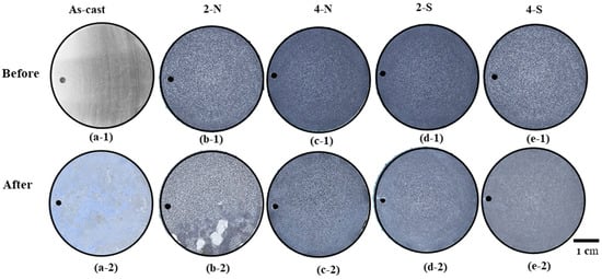
Figure 11.
Appearances of the alloys, anodized and sealed before salt spray testing after 14 days: (a-1) and (a-2) as-cast A535 alloy; (b-1) and (b-2) 2-N; (c-1) and (c-2) 4-N; (d-1) and (d-2) 2-S; and (e-1) and (e-2) 4-S (optical microscopy).
Figure 12 shows SEM images of the surface of the sample etched by alkaline solution for 2 min and sealed with NiF2 after exposure in 5 wt.% NaCl for 336 h. Obviously, the oxide film is cracked, and shallow local corrosion occurs in the places where the oxide layer is severely damaged or chipped off. This damage can be facilitated by infiltration of the nickel fluoride sealant that reacts with the Al-matrix substrate, forming corrosive products of Al(OH)3, Ni(OH)2, and AlF3 [37] (see Figure 11a). These products deposit on the surface after corrosion reaction.

Figure 12.
Corroded area of a 2-N sample after salt spray testing: SEM images in (a,b) from the inset in the optical micrograph in (c).
The difference between different sealants is illustrated in Figure 13. It shows the surface morphology of the anodized and sealed samples after the salt spray test. In the case of a 2-N sample shown in Figure 13a, it reveals the cracked oxide film, and there are corrosion products deposited on the surface. This may be caused by the pitting corrosion after the oxide film broke and the chloride solution reacted with the Al substrate and formed Al(OH)3 [47]. It was reported that the chlorine ions absorbed on the surface and corroded the films, and the dissolution on the surface caused the corrosion pits and immediately decreased the hardness of the oxide film [48]. In addition, the oxide film of a 4-N sample was destroyed but there are no corrosion products, which indicates that, although the anodic oxide film has been damaged, it still prevents the chemical reaction with Al matrix (Figure 13b). However, it was found that the alloy etched for 2 min and sealed with stearic acid had a better surface after exposure to chloride solution, as can be seen in Figure 13c. This may be explained from the propagation of the petal shaped sealing film, which can reduce the corrosion. On the other hand, the oxide layer on a 4-S sample showed the corroded area on the petal shaped sealing film in Figure 13d. Moreover, it can be seen the petal shaped pattern still covers the anodic oxide film. This may be caused by a higher thickness layer of sealing film in the 4-S sample, as shown in Figure 8f. The higher thickness of the sealing layer can be also related to the pretreatment surface that had less intermetallics and more groove area on the surface after etching for 4 min. These data suggest that the stearic sealing improves the general corrosion resistance. The initially hydrophobic film formed by stearic acid can be transformed to a layer of fatty soaps by a chemical reaction with alumina, facilitating the access of the stearic acid to the oxide film and sealing of the surface irregularities [22,49], which agrees well with our data in Figure 5, which shows a lower pore fraction in 4-S samples.

Figure 13.
Surface morphology of the anodized and sealed samples after salt spray test: (a) 2-N; (b) 4-N; (c) 2-S; and (d) 4-S (SEM).
3.3.2. Electrochemical Corrosion Behavior
Figure 14 shows the potentiodynamic polarization curves of specimens that were prepared with different pretreatment etching time (2 min and 4 min) and sealed with nickel fluoride and steric acid after anodic film coating. The quantitative results of the potentiodynamic tests are summarized in Table 4. Technically, the more positive the electrochemical corrosion potential (Ecorr) and the smaller the corrosion current density (Icorr), the better the material corrosion resistance. The corrosion potential (Ecorr) of the substrate sealed by NiF2 has a lower value (Ecorr = −0.58V) for the 2-N condition as compared to the stearic acid sealing (Ecorr = −0.53V). At the same time, the Icorr for this condition is significantly higher (Icorr = 9.40 × 10⁻⁷ mA/cm2) than for the samples sealed with stearic acid (Icorr = 8.15 × 10⁻⁹ mA/cm2). This increase of the corrosion current density can be attributed to the presence of intermetallic particles on the alkaline etched surface [50], as we observed in Figure 3.

Figure 14.
Polarization curves of A535 specimens with different etching time and sealants were tested in a 5 wt.% NaCl solution.
Table 4.
Corrosion parameters of anodic coefficient (), cathodic coefficient (βc), potential (Ecorr), and corrosion current density (Icorr) of the tested samples obtained from a Tafel curve.
Moreover, the polarization curve instability of the oxide film can be clearly seen, as we discussed in relation to Figure 13 and Figure 14. It shows the onset of localized corrosion. The pitting potential is determined in the anodic branch of the polarization curve with the Epit value of 0.5 V in Figure 14, which corresponds to the potential associated with the dissolution of the passive film, formed by oxides or even by corrosion products. Breakdown of oxide film is indicated by the localized corrosion in Figure 15a. This may be caused by the remaining intermetallics present on surface; when the passive oxide cracks, these intermetallics can react with the solution and then increase the positive charges in the electrolyte concentration [51]. Similar corrosion behavior was reported when the potential value changed to positive after the passivation region in an aluminum alloy, which was associated with the electrolyte concentration and corrosive environment that accompanied localized corrosion [51,52,53].
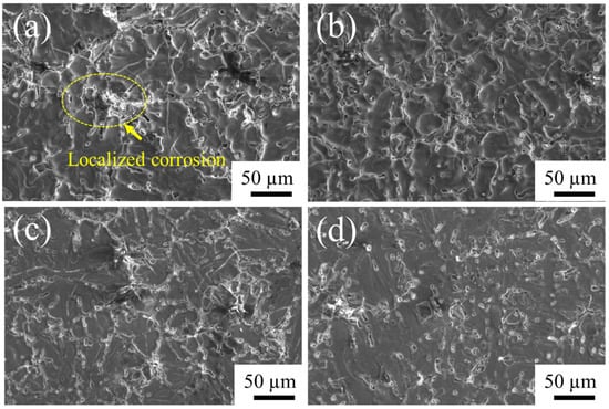
Figure 15.
SEM micrographs of A535 specimens after the electrochemical corrosion testing in 5 wt.% NaCl solution: (a) 2-N, (b) 4-N, (c) 2-S, and (d) 4-S.
The intermetallics in question are most likely the remaining Al3Mg2 intermetallics in the alloy that was alkaline etched for only 2 min, as these intermetallics have a low corrosion potential of about (−1.5 V) to (−1.3 V) vs. the saturated calomel electrode (SCE) that commonly acts as an active cathodic electrode [5,7]. As the corrosion reaction goes, the oxide film degrades, and the oxidation reaction of the active intermetallic Al3Mg2 takes place with the electrolytic solution. However, the detrimental effect of intermetallics can be alleviated by alkaline etching for 4 min and sealing with stearic acid, as can be seen in Figure 14. It is clear that the alloy alkaline etched for 4 min and sealed with stearic acid has a higher corrosion potential (Ecorr = −0.35 V) as compared to the alloy that was etched for 4 min sealed by NiF2 that has Ecorr of −0.85 V, which indicates that the metal oxidation is low at the stage of corrosion reaction. It was reported that the corrosion potential of the alloy depends on the type of the active intermetallic [7] and the type of sealants, and it was shown that these films had strong hydrophobic properties and improved the surface hardness [24,37,44].
The morphology of the oxide film formed after different etching times and sealing after the electrochemical corrosion in 5 wt.% NaCl solution are shown in Figure 15. After 2 min of alkaline etching and sealing with either of the two sealants, the corroded surface shows voids similar to corrosion pits (Figure 15a,b). In contrast, the exposed surface of a sample subjected to 4-min alkaline etching and sealed with stearic acid (Figure 15d) is pore-free and appears to be more uniform that that for the 4-N sample (Figure 15b). This observation is further confirmed by a closer observation of the surface in Figure 16. It shows that the corrosion pits on the oxide film sealed with NiF2 are about 5–10 µm, whereas the alloy sealed with stearic acid still has a petal-shape layer on the surface, which is beneficial for the corrosion resistance.

Figure 16.
SEM micrographs of anodized samples after electrochemical corrosion testing in 5 wt.% NaCl solution: (a) 4-N sample-anodized sealed with NiF2 and (b) 4-S sample-anodized sealed with stearic acid.
4. Conclusions
The surface of as-cast A535 alloy samples after different alkaline etching times and anodizing and sealing with either nickel fluoride (NiF2) or stearic acid was studied, and its effect on the corrosion performance of the anodic oxide film was evaluated through salt spray and electrochemical testing. The key conclusions are drawn as follows:
- A suitable alkaline etching time of 4 min can effectively remove intermetallic particles from the matrix surface, providing the grooved surface with higher roughness for anodic oxide film growth. In addition, at a lower etching time, the corroded surface showed local pitting, which resulted from the remaining intermetallics that reacted with the electrolyte and increased the positive charges in the corroded area.
- Etching the surface of the alloy for 4 min assured lower porosity and more uniform anodic film with a sufficiently large thickness of up to 70 µm, with the maximum hardness of 550 HV.
- The corrosion resistance of an A535 alloy can be improved by sealing with stearic acid, which provided better quality of the sealed layer than NiF2 due to the fewer reaction products and improved wettability.
- After a salt spray test for 336 h, the samples sealed with stearic did not show pitting sites and corrosion products.
- The corrosion behavior evaluated by polarization fitting curves revealed that the anodic oxide film sealed with stearic had better corrosion resistance compared to the anodic oxide film sealed with NiF2, which was quantified by the lower corrosion current density (Icorr).
Highlights
- Alkaline etching can remove intermetallic particles at the surface of an A535 alloy.
- Remaining intermetallic phase on the alkaline etched surface was responsible for the current density changing, which lead to pitting corrosion.
- Etching for 4 min produces better surface adhesion of the anodic film and fewer voids.
- An anodized A535 alloy sealed by stearic acid has better corrosion resistance.
Author Contributions
S.C.: formal analysis, writing—original draft preparation; D.E.: supervision, writing—reviewing and editing; C.L.: funding acquisition, writing—reviewing and editing; N.K.: formal analysis, investigation, and resources; O.D.: conceptualization, formal analysis, data curation, and writing—reviewing and editing. All authors have read and agreed to the published version of the manuscript.
Funding
This work was supported by the Research Strengthening of academic year 2563, the Project of Faculty of Engineering, King Mongkut University of Technology Thonburi year 2020.
Institutional Review Board Statement
Not applicable.
Informed Consent Statement
Not applicable.
Data Availability Statement
Not applicable.
Acknowledgments
The authors are grateful to Patchalin Chutimakul, Natchanon Phumyeam, and Wasinchai Jruyodtanapat for experiments. This work was supported by the Research Strengthening, the Project of Faculty of Engineering, King Mongkut University of Technology Thonburi year 2020. The authors also would like to thank the Department of Tool and Materials Engineering and Production Engineering Department, King Mongkut’s University of Technology Thonburi laboratory facilities. We highly appreciate to FE-SEM center at school of engineering, King Mongkut’s Institute of Technology Ladkrabang for advanced characterization.
Conflicts of Interest
The authors declare no conflict of interest.
References
- Fasoyinu, F.; Cousineau, D.; Sahoo, M. Marrying Almag 535 to the permanent mold process. Mod. Cast. 2005, 95, 43–45. [Google Scholar]
- Fasoyinu, F.; Thomson, J.; Castles, T.; Sahoo, M. Mechanical Properties and Metallography of Al-Mg Alloy 535.0. AFS Trans. 2003, 3, 1–13. [Google Scholar]
- Kaufman, J.G.; Rooy, E.L. Aluminum Alloy Castings, Properties, Processes and Applications; ASM International: Almere, The Netherlands, 2004. [Google Scholar]
- Speidel, M.O. Stress corrosion cracking of aluminum alloys. Met. Mater. Trans. A 1975, 6, 631–651. [Google Scholar] [CrossRef]
- Jones, R.H.; Baer, D.R.; Danielson, M.J.; Vetrano, J.S. Role of Mg in the stress corrosion cracking of an Al-Mg alloy. Met. Mater. Trans. A 2001, 32, 1699–1711. [Google Scholar] [CrossRef]
- Baer, D.R.; Windisch, C., Jr.; Engelhard, M.H.; Danielson, M.J.; Jones, R.H.; Vetrano, J.S. Influence of Mg on the corrosion of Al. J. Vac. Sci. Technol. A Vac. Surf. Film. 2000, 18, 131–136. [Google Scholar] [CrossRef]
- Yasakau, K.; Zheludkevich, M.; Ferreira, M. Role of intermetallics in corrosion of aluminum alloys. Smart corrosion protection. In Intermetallic Matrix Composites; Elsevier: Amsterdam, The Netherlands, 2018; pp. 425–462. [Google Scholar] [CrossRef]
- Li, Z.; Yi, D.; Tan, C.; Wang, B. Investigation of the stress corrosion cracking behavior in annealed 5083 aluminum alloy sheets with different texture types. J. Alloys Compd. 2019, 817, 152690. [Google Scholar] [CrossRef]
- Yan, J.; Heckman, N.M.; Velasco, L.; Hodge, A.M. Improve sensitization and corrosion resistance of an Al-Mg alloy by optimization of grain boundaries. Sci. Rep. 2016, 6, 26870. [Google Scholar] [CrossRef]
- Zhang, P.; Zuo, Y.; Zhao, X.; Tang, Y.; Zhang, X. Correlation between microhardness and microstructure of anodic film on 2024 aluminum alloy. J. Wuhan Univ. Technol. Sci. Ed. 2015, 30, 586–590. [Google Scholar] [CrossRef]
- Li, S.-M.; Li, Y.-D.; Zhang, Y.; Liu, J.-H.; Yu, M. Effect of intermetallic phases on the anodic oxidation and corrosion of 5A06 aluminum alloy. Int. J. Miner. Met. Mater. 2015, 22, 167–174. [Google Scholar] [CrossRef]
- Abdel-Gawad, S.A.; Osman, W.M.; Fekry, A.M. Characterization and corrosion behavior of anodized Aluminum alloys for military industries applications in artificial seawater. Surf. Interfaces 2018, 14, 314–323. [Google Scholar] [CrossRef]
- Iewkitthayakorn, I.; Janudom, S.; Mahathaninwong, N.; Karrila, S.; Wannasin, J. Anodizing parameters for superheated slurry cast 7075 aluminum alloys. Trans. Nonferrous Met. Soc. China 2019, 29, 1200–1210. [Google Scholar] [CrossRef]
- Zhu, B. On the Influence of Si on Anodising and Mechanical Properties of Cast Aluminium Alloys. Ph.D. Thesis, Jönköping University, Jönköping, Sweden, 2017. [Google Scholar]
- Berlanga-Labari, C.; Biezma-Moraleda, M.V.; Rivero, P.J. Corrosion of Cast Aluminum Alloys: A Review. Metals 2020, 10, 1384. [Google Scholar] [CrossRef]
- Konieczny, J.; Labisz, K.; Polok-Rubiniec, M.; Włodarczyk-Fligier, A. Influence of Aluminium Alloy Anodizing and Casting Methods on Structure and Functional Properties. Arch. Met. Mater. 2016, 61, 1337–1342. [Google Scholar] [CrossRef][Green Version]
- Jothi, V.; Adesina, A.Y.; Kumar, A.M.; Al-Aqeeli, N.; Ram, J.N. Influence of an anodized layer on the adhesion and surface protective performance of organic coatings on AA2024 aerospace Al alloy. Prog. Org. Coat. 2019, 138, 105396. [Google Scholar] [CrossRef]
- Bruera, F.; Kramer, G.; Vera, M.; Ares, A. Evaluation of surface pretreatment stages of Al 1050 to obtain nanostructured anodic films. Superlattices Microstruct. 2019, 130, 103–116. [Google Scholar] [CrossRef]
- Leontiev, A.; Roslyakov, I.; Napolskii, K. Complex influence of temperature on oxalic acid anodizing of aluminium. Electrochim. Acta 2019, 319, 88–94. [Google Scholar] [CrossRef]
- Aggerbeck, M.; Canulescu, S.; Dirscherl, K.; Johansen, V.E.; Engberg, S.; Schou, J.; Ambat, R. Appearance of anodised aluminium: Effect of alloy composition and prior surface finish. Surf. Coat. Technol. 2014, 254, 28–41. [Google Scholar] [CrossRef]
- Yu, S.; Wang, L.; Wu, C.; Feng, T.; Cheng, Y.; Bu, Z.; Zhu, S. Studies on the corrosion performance of an effective and novel sealing anodic oxide coating. J. Alloys Compd. 2020, 817, 153257. [Google Scholar] [CrossRef]
- Ofoegbu, S.U.; Fernandes, F.A.; Pereira, A.B. The Sealing Step in Aluminum Anodizing: A Focus on Sustainable Strategies for Enhancing Both Energy Efficiency and Corrosion Resistance. Coatings 2020, 10, 226. [Google Scholar] [CrossRef]
- Cartigny, V.; Veys-Renaux, D.; Desenne, P.; Rocca, E. Rapid sealing of an alumina nanoporous network grown by anodizing and dye-filled. Surf. Coat. Technol. 2019, 364, 369–376. [Google Scholar] [CrossRef]
- Boisier, G.; Lamure, A.; Pébère, N.; Portail, N.; Villatte, M. Corrosion protection of AA2024 sealed anodic layers using the hydrophobic properties of carboxylic acids. Surf. Coat. Technol. 2009, 203, 3420–3426. [Google Scholar] [CrossRef]
- Jothi, V.; Adesina, A.Y.; Kumar, A.M.; Ram, J.S.N. Influence of Organic Acids on the Surface and Corrosion Resistant Behavior of Anodized Films on AA2024 Aerospace Alloys in Artificial Seawater. Met. Mater. Int. 2019, 26, 1611–1620. [Google Scholar] [CrossRef]
- El-Hameed, A.M.A.; Abdel-Aziz, Y.A.; El-Tokhy, F.S. Anodic Coating Characteristics of Different Aluminum Alloys for Spacecraft Materials Applications. Mater. Sci. Appl. 2017, 8, 197–208. [Google Scholar] [CrossRef]
- Jo, H.; Lee, S.; Kim, D.; Lee, J. Low Temperature Sealing of Anodized Aluminum Alloy for Enhancing Corrosion Resistance. Materials 2020, 13, 4904. [Google Scholar] [CrossRef]
- Chankitmunkong, S.; Eskin, D.G.; Limmaneevichitr, C.; Pandee, P.; Kengkla, N.; Athchasiri, J.; Tanawansombat, T.; Parnlasarn, N.; Diewwanit, O. Effect of Homogenization on Anodic Film and Electrochemical Behavior of an A535 Alloy After Sealing with Stearic Sealant. In Light Metals; Springer: Berlin/Heidelberg, Germany, 2022; pp. 221–227. [Google Scholar] [CrossRef]
- Shang, Y.; Wang, L.; Liu, Z.; Niu, D.; Wang, Y.; Liu, C. The Effects of Different Sealing Techniques for Anodic Film of Al-12.7 Si 0.7 Mg Alloys. Int. J. Electrochem. Sci. 2016, 11, 5234–5344. [Google Scholar] [CrossRef]
- Medvedev, O.S.; Alyasova, E.E.; Besprozvannaya, R.E.; Gadzhiev, A.A.; Krivova, V.V.; Kondratev, A.S.; Kim, A.E.; Novikov, P.A.; Popovich, A.A. Influence of Alloying Elements on the Mechanical Properties of Anodized Aluminum and on the Adhesion of Copper Metallization. Materials 2021, 14, 7028. [Google Scholar] [CrossRef]
- Li, K.; Li, W.; Yi, A.; Zhu, W.; Liao, Z.; Chen, K.; Li, W. Tuning the Surface Characteristic of Al-Si Alloys and Its Impacts on the Formation of Micro Arc Oxidation Layers. Coatings 2021, 11, 453. [Google Scholar] [CrossRef]
- Sadeghpour-Motlagh, M.; Mokhtari-Zonouzi, K.; Aghajani, H.; Kakroudi, M.G. Effects of Etching Time and NaOH Concentration on the Production of Alumina Nanowires Using Porous Anodic Alumina Template. J. Mater. Eng. Perform. 2014, 23, 2007–2014. [Google Scholar] [CrossRef]
- Jin, Z.; Cai, C.; Hashimoto, T.; Yuan, Y.; Kang, D.; Hunter, J.; Zhou, X. Alkaline etching and desmutting of aluminium alloy: The behaviour of Mg2Si particles. J. Alloys Compd. 2020, 842, 155834. [Google Scholar] [CrossRef]
- Jin, Z.; Cai, C.; Yuan, Y.; Kang, D.; Hunter, J.; Zhou, X. The behaviour of AA5754 and AA5052 aluminium alloys in alkaline etching solution: Similarity and difference. Mater. Charact. 2020, 171, 110768. [Google Scholar] [CrossRef]
- Shi, H.; Yu, M.; Liu, J.; Rong, G.; Du, R.; Wang, J.; Li, S. Effect of alkaline etching on microstructure and anticorrosion performance of anodic film on Al-Mg-Si alloy. Corros. Sci. 2020, 169, 108642. [Google Scholar] [CrossRef]
- Kaseem, M.; Yang, H.W.; Ko, Y.G. Toward a nearly defect-free coating via high-energy plasma sparks. Sci. Rep. 2017, 7, 2378. [Google Scholar] [CrossRef] [PubMed]
- Zuo, Y.; Zhao, P.-H.; Zhao, J.-M. The influences of sealing methods on corrosion behavior of anodized aluminum alloys in NaCl solutions. Surf. Coat. Technol. 2003, 166, 237–242. [Google Scholar] [CrossRef]
- Kalantary, M.R.; Gabe, D.R.; Ross, D.H. A model for the mechanism of nickel fluoride cold sealing of anodized aluminium. J. Appl. Electrochem. 1992, 22, 268–276. [Google Scholar] [CrossRef]
- Boisier, G.; Pébère, N.; Druez, C.; Villatte, M.; Suel, S. FESEM and EIS study of sealed AA2024 T3 anodized in sulfuric acid electrolytes: Influence of tartaric acid. J. Electrochem. Soc. 2008, 155, C521. [Google Scholar] [CrossRef]
- Saleema, N.; Sarkar, D.; Paynter, R.; Gallant, D.; Eskandarian, M. A simple surface treatment and characterization of AA 6061 aluminum alloy surface for adhesive bonding applications. Appl. Surf. Sci. 2012, 261, 742–748. [Google Scholar] [CrossRef]
- Kocabaş, M.; Curioni, M.; Cansever, N. The effect of anodic oxidation conditions on the structure of dual pre-treatment electroless nickel coating on AA1050 surface. Surf. Coat. Technol. 2019, 364, 321–328. [Google Scholar] [CrossRef]
- Lee, J.; Kim, Y.; Jang, H.; Chung, W. Cr2O3 sealing of anodized aluminum alloy by heat treatment. Surf. Coat. Technol. 2012, 243, 34–38. [Google Scholar] [CrossRef]
- Cheng, T.-C.; Chou, C.-C. The Electrical and Mechanical Properties of Porous Anodic 6061-T6 Aluminum Alloy Oxide Film. J. Nanomater. 2015, 2015, 371405. [Google Scholar] [CrossRef]
- Mihajlović, S.; Sekulić, Ž.; Daković, A.; Vučinić, D.; Jovanović, V.; Stojanović, J. Surface properties of natural calcite filler treated with stearic acid. Ceram. Silikáty 2009, 53, 268–275. [Google Scholar]
- Zhang, X.; Wu, G.; Peng, X.; Li, L.; Feng, H.; Gao, B.; Huo, K.; Chu, P.K. Mitigation of Corrosion on Magnesium Alloy by Predesigned Surface Corrosion. Sci. Rep. 2015, 5, 17399. [Google Scholar] [CrossRef] [PubMed]
- Usman, B.J.; Scenini, F.; Curioni, M. Corrosion Testing of Anodized Aerospace Alloys: Comparison Between Immersion and Salt Spray Testing using Electrochemical Impedance Spectroscopy. J. Electrochem. Soc. 2020, 167, 041505. [Google Scholar] [CrossRef]
- Materia, T. Corrosion of Aluminum and Its Alloys: Forms of Corrosion. Total Mater. 2008. Available online: http://www.keytometals.com/page.aspx?ID=CheckArticle&site=ktn&NM=187 (accessed on 25 June 2022).
- Wu, Y.; Zhao, W.; Wang, W.; Wang, L.; Xue, Q. Novel anodic oxide film with self-sealing layer showing excellent corrosion resistance. Sci. Rep. 2017, 7, 1344. [Google Scholar] [CrossRef]
- Shulman, G.P.; Bauman, A. Organic acid sealants for anodized aluminum—A new method for corrosion protection. Met. Finish. 1995, 93, 16–19. [Google Scholar] [CrossRef]
- Golru, S.S.; Attar, M.; Ramezanzadeh, B. Effects of different surface cleaning procedures on the superficial morphology and the adhesive strength of epoxy coating on aluminium alloy 1050. Prog. Org. Coat. 2015, 87, 52–60. [Google Scholar] [CrossRef]
- Brito, C.; Vida, T.; Freitas, E.; Cheung, N.; Spinelli, J.E.; Garcia, A. Cellular/dendritic arrays and intermetallic phases affecting corrosion and mechanical resistances of an Al–Mg–Si alloy. J. Alloys Compd. 2016, 673, 220–230. [Google Scholar] [CrossRef]
- Zaid, B.; Saidi, D.; Benzaid, A.; Hadji, S. Effects of pH and chloride concentration on pitting corrosion of AA6061 aluminum alloy. Corros. Sci. 2008, 50, 1841–1847. [Google Scholar] [CrossRef]
- Malina, J.; Radošević, J. Influence of NaCl concentration on pitting corrosion of extruded Al-Mg-Si alloy AA6060. Zaštita Mater. 2015, 56, 47–51. [Google Scholar] [CrossRef]
Publisher’s Note: MDPI stays neutral with regard to jurisdictional claims in published maps and institutional affiliations. |
© 2022 by the authors. Licensee MDPI, Basel, Switzerland. This article is an open access article distributed under the terms and conditions of the Creative Commons Attribution (CC BY) license (https://creativecommons.org/licenses/by/4.0/).