Article

Immune Optimization of Double-Sided Welding Sequence for Medium-Small Assemblies in Ships Based on Inherent Strain Method

1
School of Mechanics and Power Engineering, Jiangsu University of Science and Technology, Zhangjiagang 215600, China
2
School of Mechanics and Power Engineering, Suzhou Institute of Technology, Jiangsu University of Science and Technology, Zhangjiagang 215600, China
3
Suzhou SmartImageAI Technology Co., Ltd., Zhangjiagang 215600, China
*
Author to whom correspondence should be addressed.
Metals 2022, 12(7), 1091; https://doi.org/10.3390/met12071091
Submission received: 13 May 2022 / Revised: 20 June 2022 / Accepted: 23 June 2022 / Published: 26 June 2022
(This article belongs to the Topic Development of Friction Stir Welding and Processing)

Abstract

:
The double-sided welding process is widely used in ship construction due to its high welding efficiency and forming quality. In order to further reduce the deformation caused by double-sided welding for medium-small assemblies in ships, the optimization of the double-sided welding sequence based on an artificial immune algorithm is carried out. First, the formation mechanism of welding deformation under the double-sided welding process is analyzed by the inherent strain method; next, the reduction of the welding deformation is taken as the optimization goal, and the welding sequence optimization model for double-sided welding is constructed; then, an immune clonal optimization algorithm based on similar antibody similarity screening and steady-state adjustment is introduced, and the immune optimization process for double-sided welding sequence is designed; finally, double-sided welding sequence optimization tests are carried out for four different types of medium-small assemblies in ships. Numerical test results show that, compared with IGA (Immune genetic algorithm), ICA (Immune clonal algorithm), and GA (Genetic algorithm), the maximum welding deformation caused by the welding sequence optimized by the proposed immune clonal algorithm is reduced by 2.4%, 2.8, and 3.3%, respectively, the average maximum welding deformation is reduced by 2.6%, 2.5, and 3.4%, respectively, and the convergence generation is reduced by 16.2%, 13.4, and 11.2%, respectively, which verifies the strong optimization ability and high optimization efficiency of the immune clonal algorithm introduced in the double-sided welding sequence optimization.

1. Introduction

There are a large number of thick plate assemblies in ship construction, and the thick plate assemblies are prone to quality problems such as pores and lack of penetration during single-sided welding [1]. Therefore, for the welding of thicker plates, the double-sided welding process is usually adopted. Different from single-sided welding, the front and reverse sides of the base metal are heated evenly during double-sided synchronous welding, and the root welding is formed at one time, and there is no need to clean the root of the weld [2]. Therefore, for thick plates, the double-sided synchronous welding process is often superior to the single-sided welding process in terms of welding quality and welding efficiency. In view of this, the differences between single-sided welding and double-sided welding and how to improve the efficiency and welding quality of double-sided welding have attracted the attention of scholars at home and abroad. Li et al. compared and analyzed the residual stress and deformation of the T-shaped plate after single-sided welding and double-sided welding [3]. The analysis shows that the maximum residual stress generated by single-sided welding at the selected points on the structure is about 200 MPa lower than that of double-sided welding, and the deformation value is 0.12 mm smaller. For the 30 mm thick 7A52 aluminum alloy sheet, Chen et al. carried out single-sided and double-sided welding experiments [4]. The experimental results show that compared with single-sided welding, double-sided welding refines the microstructure grains of the first weld, and the tensile strength of the structure after double-sided welding is significantly improved. In view of the great influence of different welding speeds on the weld formation quality, Tang et al. carried out double-sided friction stir welding experiments on 1060 pure aluminum and T2 copper at different welding speeds [5]. The experimental results show that when the welding speed is 50 mm/min, the base metal receives enough heat input, the molten part produced has sufficient fluidity, and hole defects are not easily generated in the welded joint, so the bearing area is large and the tensile strength is higher. Sun et al. [6] conducted an experimental analysis on the performance changes of double-sided welded joints of aluminum alloy sheets. The experimental results show that compared with single-sided welding, the stress generated by double-sided welding is basically compressive stress, and only a small range of tensile stress is generated on the plate. In order to solve the problems of low welding efficiency and high welding cost during single-sided welding of large-scale storage tank girth welds, Sun et al. [7] developed a double-sided welding process for large-scale storage tank girth welds. By using one set of traveling mechanisms and two sets of independent welding torch power sources, the welding process is more concise and the welding efficiency is improved. Zhou et al. [8] compared and analyzed the characteristics of different dual-arc high-efficiency welding technologies. The experimental results show that double TIG welding effectively solves the problem of low arc energy density in traditional TIG welding. In addition, at higher welding speeds, traditional TIG welding will cause various defects in the weld due to low arc pressure, while double TIG welding can effectively adapt to high welding speeds. Liu et al. [9] carried out some numerical simulation and prediction studies on the residual stress distribution of the Q345 volute-seat ring welds under different welding sequences. The numerical calculation results show that the magnitude and position of the peak value of residual stress generated by different welding sequence schemes are different. When both sides of the volute are welded simultaneously, the resulting stress peak is minimal. Liu et al. [10] carried out a study on the effect of welding sequence on welding residual stress and deformation of Q345 lateral stop. The numerical simulation and experimental comparison show that the welding sequence of the assembly welding plays a major role in the influence of the maximum residual stress of the lateral stop, and a good welding sequence can effectively control the welding residual stress and welding deformation. Luo et al. [11] comparatively analyzed the residual stress distribution of Q345 steel T-joints under different welding sequences. The calculation results show that the transverse residual stress can be reduced by changing the welding sequence on the path perpendicular to the weld. Along the path in the direction of the welding seam, the longitudinal residual stress at the end of the welding seam varies significantly due to different secondary heating cycles. From the existing research, it can be seen that there are few research studies on the optimization of the welding sequence for the double-sided welding process, especially the welding sequence optimization of the double-sided welding for medium-small assemblies in ships. For this reason, for the typical medium-small assemblies in ship construction, the welding simulation calculation under the double-sided welding process is carried out in this paper, and the deformation of the base metal after welding is analyzed. In addition, the welding sequence is distributed and globally optimized through an optimization algorithm to reduce welding deformation caused by double-sided welding.

2. Theoretical Analysis and Model Construction of Thermal Deformation

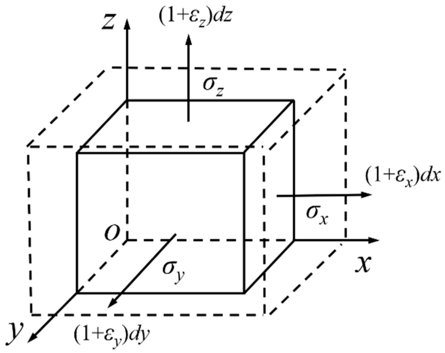
2.1. Inherent Strain Theory

The plate of the medium-small assemblies in ships is relatively thick, and there will be dual heat sources acting on the plate at the same time when the double-sided welding process is adopted. Compared with the action of a single heat source, the construction of a temperature field for a dual heat source will be more difficult, which will eventually lead to a significant increase in the calculation time of welding deformation. Therefore, the inherent strain method is introduced in this paper to model and analyze the welding deformation. The intrinsic strain method is an efficient method for predicting welding deformation [12]. In the inherent strain theory, the thermal strain εt, plastic strain εp, and phase transformation strain εc generated in the base metal during welding together lead to the deformation of the welded structure. The sum of thermal strain εt, plastic strain εp, and transformation strain εc is the intrinsic strain ε*, as shown in Equation (1).
{ ε } = { ε p } + { ε t } + { ε c }

2.2. Calculation of Intrinsic Strain Increments

During the double-sided welding process, two heat sources transfer heat to the weldment at the same time. According to the principle of temperature field superposition [13], the solution of the temperature field of the weldment under the action of multiple heat sources is simplified, that is, the temperature at any point of the base metal is equal to the sum of the base metal temperatures when each heat source acts on the weldment alone, as shown in Equation (2).
T = k = 1 n T k ( x i , y i , z i )
where T is the temperature of the base metal, n is the number of heat sources, Tk(xi,yi,zi) is the temperature of any point on the base metal when the heat source k acts on the weldment alone.
According to the thermal elastic-plastic finite element theory, it is assumed that the total strain increment in the elastic region after the material yields is composed of elastic strain increment and thermal strain increment, as shown in Equation (3).
{ d ε } = { d ε e l } + { d ε t }
where {} is the total strain increment, {el} is the elastic strain increment, {t} is the thermal strain increment.
Under the action of the heat source, the internal material of the base metal will generate the forces as shown in Figure 1 due to expansion and contraction.
Establish the constitutive relationship between strain and stress as shown in Equation (4), and differentiate it to obtain Equation (5).
{ ε e l } = [ E ] e l 1 { σ e l }
where [E]el is the elastic matrix and σel is the elastic region stress.
{ d ε e l } = d [ [ E ] e l 1 { σ e l } ] = [ E ] e l 1 { d σ e l } = [ E ] e l 1 T { σ e l } d T
The thermal strain increment is related to the coefficient of linear expansion, as shown in Equation (6).
{ d ε t } = { α 0 d T + T d α 0 } = { α 0 + α 0 T T } d T
where α0 is the initial linear expansion coefficient of the base metal.
In the plastic region of the base metal, the composition of the total strain increment is shown in Equation (7).
{ d ε } = { d ε e l } + { d ε p } + { d ε t }
where {p} is the increment of plastic strain.
According to the flow criterion, the plastic strain increment is:
{ d ε p } = [ { f T σ } [ E ] e l { d ε p } { f T σ p } [ E ] e l ( { a } + [ E ] e l 1 T { σ p } ) d T ] { f σ p } D 1
where f is the yield function of the base metal, σp is the stress in the plastic region.
D can be described as:
D = { f σ p } [ E ] e l { f σ p } + ( f k ) { K ε p } T { f σ p }

2.3. Calculation of Welding Deformation

When the welding base metal is low carbon steel, the influence of thermal strain εt and transformation strain εc on welding deformation is generally ignored [14]. In addition, because the post-weld residual deformation of low-carbon metal materials is mainly related to the plastic strain generated near the weld, the longitudinal shrinkage deformation δ L * and transverse shrinkage deformation δ T * of the welded parts after welding can be obtained by defining the height h of the base metal plastic strain zone, the transverse plastic strain ε L p , and the longitudinal plastic strain ε T p , as shown in Equations (10) and (11).
δ L = 1 h ε L p d y d z
δ T = 1 h ε T p d y d z

3. Construction of Welding Sequence Optimization Model for Double-Sided Welding

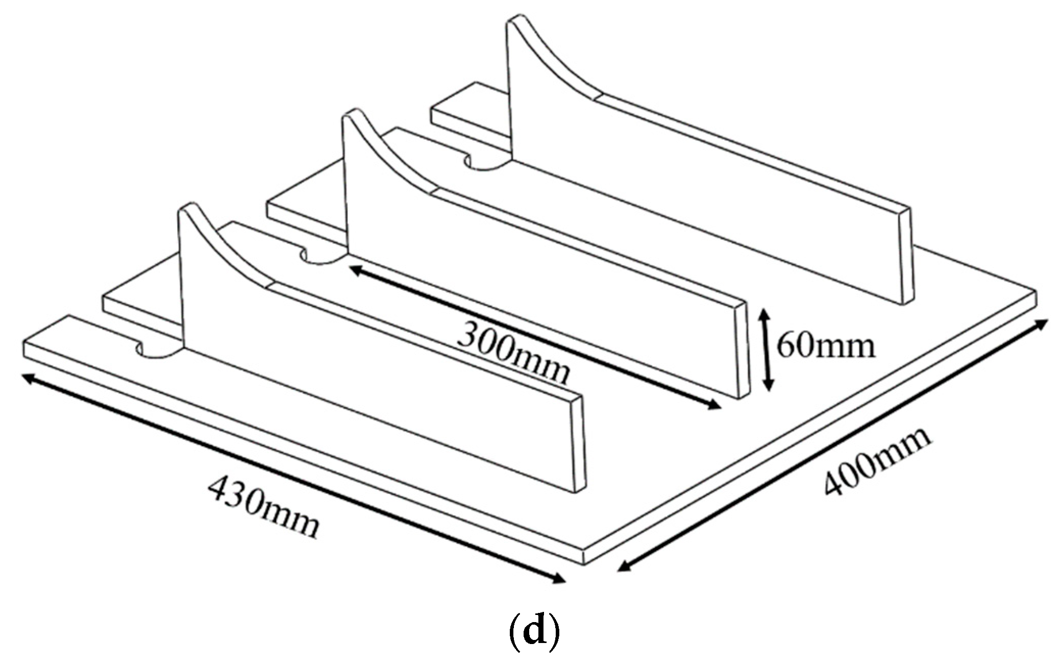
3.1. Construction of 3D Model of Double-Sided Welding for Medium-Small Assemblies in Ships

The double-sided co-directional welding of thick plates based on a welding robot can not only greatly improve the welding efficiency but also have smaller deformation and higher welding quality than single-sided welding. In order to facilitate the construction of the welding sequence optimization model, Figure 2 shows the 3D welding model for double-sided welding of corner joints.
In view of the characteristics of the same direction and the same speed of the double-sided welding, the welds on both sides of the thick plate are regarded as a complete entity when building the optimization model, and the welds on both sides of the thick plate are divided according to the same scheme, that is, the welds at the same position on the thick plate are divided into the same number of segments and lengths.

3.2. Determination of Objective Function for Optimization of Double-Sided Welding Sequence

The medium-small assemblies in ships usually have the characteristics of a large number and a long length of welds. Different welding sequences will affect the deformation during the double-sided welding process of the ship welding robot. In order to realize the optimal selection of welding sequence, the objective function shown in Equation (12) is established in this paper by taking the welding seam number xi (i∈[1, n]) in Figure 2 as a variable and reducing the welding deformation as the optimization goal.
min f ( x 1 , x 2 , , x n ) = i = 1 n ( ( δ L ) 2 + ( δ T ) 2 ) 1 / 2
where n is the total number of welds.

3.3. Construction of Finite Element Models for Welding

In the process of constructing the welding finite element model, Q345R steel is selected as the material, which is widely used in shipbuilding, and the changes in the mechanical properties of the base metal at different temperatures are shown in Table 1 [15].
The constructed 3D model of double-sided welding is transformed into a finite element model by meshing, and solid70 [16] is selected as the mesh element. The heating temperature change of the unit under the action of the temperature field is shown in Figure 3, where Hgen is the heat generation rate, T is the node temperature, kx, ky, and kz are the thermal conductivity coefficients.
In order to improve the solution efficiency, different regions of the weldments are divided differentially according to how much they are heated. The grid size of the base metal element farther from the heat source is 10 mm, and the grid size of the welding element is 5 mm. Considering that the weldment is clamped by the fixture during the working process, the elements on the two sides of the weldment are restricted from moving during the calculation of the stress field.

4. Design of Artificial Immune Algorithm for Welding Sequence Optimization

4.1. Description of the Basic Immune Clonal Optimization Algorithm

The medium-small assemblies in ships are usually welded by multiple plates in a fillet or butt manner, so multiple weldings are required in actual production. However, the number of selectable welding sequences in welding increases exponentially with the increment of the number of welds, and it is difficult to obtain the optimal multivariable welding sequence. In recent years, with the rapid development of bionic intelligence, intelligent optimization algorithms with distributed global optimization capabilities, such as genetic algorithm [17], particle swarm optimization algorithm [18], ant colony algorithm [19], etc. have been widely used in complex multi-objective optimization. In order to realize the optimal optimization of the double-sided welding sequence of medium-small assemblies in ships based on the inherent strain method, an immune clonal optimization algorithm is introduced in this paper, which is developed on the basis of Burnet’s clone selection theory [20]. The algorithm mainly includes antibody clone, antibody mutation, antibody selection, population replenishment, and vaccine operation [21]. The basic immune algorithm flow is shown in Figure 4.
For the optimization of high-dimensional objects, the antibody of the immune clonal algorithm increases with the coding length, and antibodies with highly repetitive gene fragments will inevitably appear in the antibody population. In the iterative process of optimization, if the randomly generated complementary antibody groups are not constrained and modified, the algorithm will fall into a local optimum and the evolution speed will be slowed down. So, the immune clonal optimization algorithm based on antibody similarity screening and steady-state adjustment (ICOABAS) [22] is introduced in this paper. Compared with the basic immune clonal optimization algorithm, ICOABAS mainly improves its search efficiency by screening high-similarity antibodies in the antibody population of the welding sequence and improves its global optimization ability by vaccinating the population with a median-based high-quality vaccine.

4.2. Operator Design of ICOABAS

Assuming that the population of the kth generation is A(k)= [a1(k), a2(k), ⋯, an(k)], The antibody clonal operator Tc mainly performs asexual reproduction on A(k), namely: A′(k)←Tcc(A(k)).
  i [ 1 ,   n ] ,   a i ( k ) T c c ( a i ( k ) ) = I i × a i ( k ) ,   a i ( k ) A ( k )
where Ii is a l-dimensional unit row vector.
The antibody mutation operator Tcm mainly randomly imposes small perturbations on the gene bits of the antibody according to the mutation probability pm, and can be described as:
A ( k ) T c m ( A ( k ) / p m )
The antibody selection operator Tcs mainly selects the dominant antibodies in the population based on antibody–antigen affinity fa and antibody concentration fm, and can be described as:
A ( k ) T c s ( A ( k ) / ( λ f a ( ) + μ f m ( ) ) )
where λ and μ are scale coefficients.
The population replenishment operator Tcre is mainly performed after immune selection in order to avoid low population diversity due to high antibody similarity. First, the antibodies in the population A’’’(k) are divided into two groups, and then the gene bits between the two antibodies are compared. If the length of the same gene bits exceeds the set value, a new antibody is generated to replace one of them, and a new population S(k) is finally formed. The population replenishment operator Tcre helps to improve the global optimization efficiency of ICOABAS and can be described as:
S ( k ) T c r e ( A ( k ) )
The vaccine extraction and vaccination operator Tcin is mainly performed based on the steady-state regulation mechanism of the human environment to improve the evolutionary efficiency after population replenishment, that is, for the population S(k), its median is used to judge whether it is evenly distributed. If the antibody in S(k) spreads unevenly, the optimal antibody is extracted and the antibody population S(k) is inoculated to achieve a new population A(k + 1) with uniform distribution of antibodies. The vaccine extraction and vaccination operator Tcin helps to improve the global optimization ability of ICOABAS and can be described as:
A ( k + 1 ) T c i n ( S ( k ) )

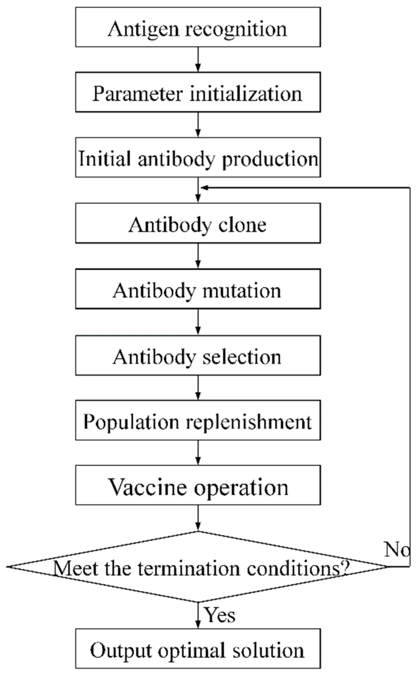
4.3. Immune Optimization Process for Double-Sided Welding Sequence

Step 1 Initialize algorithm parameters: population size n, scale coefficients λ and μ, maximum evolutionary generation kmax, etc., k←0;
Step 2 Randomly generate initial antibody populations A(0)={αi(0)|1≤in} for the double-sided welding sequence;
Step 3 Perform antibody cloning A′(k)←Tcc(A(k));
Step 4 Perform antibody mutation A″(k)←Tcm(A′(k));
Step 5 Perform numerical calculations of dual pyrogens for all antibodies based on a finite element analysis program;
Step 5.1 Extract each welding sequence antibody;
Step 5.2 Construct a finite element calculation model for the welding sequence of double-sided welding;
Step 5.3 Carry out thermal-structural coupling calculation and extract the maximum welding deformation value of nodes;
Step 6 Calculate the antibody fitness value based on the intrinsic strain method;
Step 7 Perform antibody selection A′″(k) ←Tcs(A″(k));
Step 8 Perform population replenishment S(k) ←Tcre(A′″(k));
Step 9 Perform vaccine extraction and vaccination A(k+1) ←Tcin(S(k));
Step 10 Judge whether the maximum evolutionary generation kmax is reached? If yes, output the optimal welding sequence, otherwise go to Step 3.

5. Numerical Testing and Result Analysis of Double-Sided Welding Sequence Optimization

5.1. Numerical Testing of Welding Sequence Optimization

5.1.1. Settings of Test Environment

In order to verify the effectiveness of the proposed ICOABAS in the optimization of the ship double-sided welding sequence, numerical tests are carried out on a PC platform with an Intel Core i5-4200H CPU and 8GB memory for the four types of ship welded structures shown in Figure 5, and its test results are compared with the test results of immune genetic algorithm (IGA) [23], immune clonal algorithm (ICA) [24] and genetic algorithm (GA) [25]. The algorithm parameters of ICOABAS are set as follows: the population size n is 30, the scale coefficients λ and μ are 0.8 and 0.5, respectively, and the number of clones is 10. The parameters of IGA, ICA, and GA are from their respective references. Considering the probabilistic search of intelligent optimization algorithms, 30 independent random tests are carried out on the four optimization algorithms in this paper, and the maximum evolutionary generation is 50.

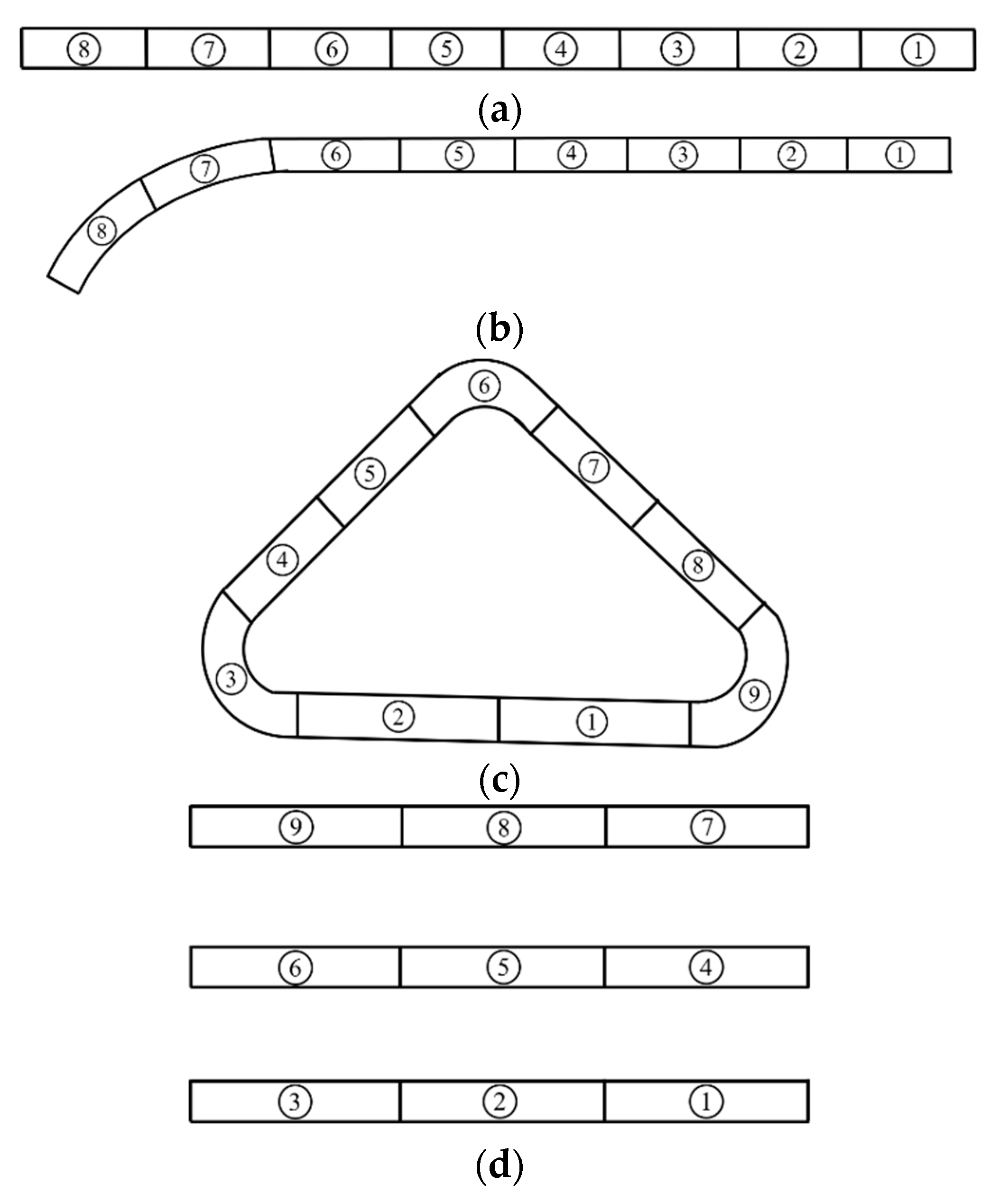
5.1.2. Division and Coding of Welding Seams

For thick plate assemblies in ship construction, double-sided welding is usually used to ensure the welding quality [26]. For long-length welding seams, the welding deformation can be reduced by using the method of segmental de-welding. However, each segment of the divided welds should not be too short, otherwise, the frequent selection and movement of the welding torch reduces welding efficiency and generates excess energy consumption. The division schemes of the welding seams in the above four welded structures are shown in Figure 6. The number in the figure is the code of the weld.

5.2. Analysis of Test Results

Table 2 gives the welding sequence optimization results of the four algorithms for the four welding structures. From the table, it can be seen that in terms of the two performance indicators of the maximum deformation and the average maximum deformation, the optimization performances of ICOABAS are the best among the four algorithms. Compared with the performance indicators of GA, ICA, and IGA, the maximum welding deformation based on ICOABAS is reduced by 2.4%, 2.8%, and 3.3%, and the average maximum deformation is reduced by 2.6%, 2.5%, and 3.4%, respectively. The smaller the deformation, the better the welding sequence, which verifies the strong global optimization capability of ICOABAS. The median-based vaccine extraction and inoculation operator in ICOABAS realizes the uniform distribution of the solution space and improves the global search ability of the algorithm. In terms of performance indicator of convergence generation, compared with the other three algorithms, ICOABAS is basically the least, and its convergence generation is reduced by 16.2%, 13.4%, and 11.2%, respectively. The smaller the convergence generation, the higher the optimization efficiency of ICOABAS. The population replenishment operator in ICOABAS realizes the initialization update of similar antibodies in the population and improves the population diversity.
Figure 7 is the evolution curves of the maximum deformation under the welding sequence optimized by the four intelligent algorithms for four welded structures. From the figure, it can also be seen that the maximum deformation caused by the welding sequence optimized by ICOABAS is the smallest and the convergence speed is the fastest, which further verifies the strong global optimization capability and high optimization efficiency of ICOABAS in the optimization of double-sided welding sequence.
Figure 8 is the deformation cloud map of the welded structure 1 under the welding sequence of “④⑤③⑥②⑦①⑧”. From Figure 8a, it can be seen that the deformation of the welded structure 1 after double-sided welding is mainly concentrated at the two ends of the weld, and the middle part of the base metal, which is far from the start and end positions of the welding seam, hardly deforms. From Figure 8b,c, it can be seen that the peak value of longitudinal deformation of the butt joint after double-sided welding is quite different from the peak value of transverse deformation, and the peak value of longitudinal deformation is more than four times the peak value of transverse deformation. After double-sided welding, two regions with uniform deformation and opposite directions are generated on the base metal.
Figure 9 is the deformation cloud map of the welded structure 2 under the welding sequence of “④⑤③⑥②①⑦⑧”. From Figure 9a, it can be seen that the deformation peak of the structure 2 after double-sided welding occurs at the boundary position on the side of the vertical plate with the arc weld, and the deformation presents a gradient decreasing trend along the axis of the welding seam. The part of the vertical plate with the straight weld is less deformed. From Figure 9b, it can be seen that the overall deformation of the structure 2 along the x-axis direction is not very different, and the deformation of each part of the base metal is relatively uniform. From Figure 9c, it can be seen that the deformation of the base metal with the arc weld along the z-axis direction is relatively large. The deformation trend of the vertical plate with the straight weld is not obvious.
Figure 10 is the deformation cloud map of the welded structure 3 under the welding sequence of “⑤⑦④⑧②①③⑨⑥”. From Figure 10a, it can be seen that both the vertical plate and the bottom plate located at the straight welding seam on the structure 3 have a deformation peak. Different degrees of deformation are produced on the vertical plate, and the deformation at the arc weld is more complicated than that at the straight weld. From Figure 10b,c, it can be seen that the deformation along the x-axis direction and the deformation peak along the z-axis direction are both generated on the bottom plate, and the produced positions are basically the same. However, the deformation peak along the x-axis direction is nearly twice as large as the deformation peak along the z-axis direction in the peak size.
Figure 11 is the deformation cloud map of the welded structure 4 under the welding sequence of “①⑦③⑨②⑧④⑥⑤”. From Figure 11a, it can be seen that the deformation peak occurs in the middle of the bottom plate boundary. Among the three vertical plates, the deformation on the middle vertical plate is more serious, while the deformation on the left and right vertical plates is relatively small and relatively close. For the symmetrical welded structure, the optimized welding sequence adopts the method of symmetrically welding both sides of the vertical plate first, and then welding the middle vertical plate, which offsets the residual stress generated by the welding to the greatest extent and reduces the deformation. From Figure 11b,c, it can be seen that the difference between the transverse and longitudinal deformation peaks of structure 4 after double-sided welding is not very large, but there is a big difference in the peak position. The peak value of longitudinal deformation is larger than the peak value of transverse deformation, and the area where the peak value of longitudinal deformation occurs on the base metal is also larger than the area where the peak value of transverse deformation occurs. The peak of lateral deformation occurs on the vertical plate, and the peak of longitudinal deformation occurs on both the vertical plate and the bottom plate.

6. Experimental Test and Result Analysis of Double-Sided Welding Sequence Optimization

6.1. Setting of Experimental Environment

In order to further verify the influence of different welding sequences on the deformation under the double-sided welding process, and the importance of the welding sequence optimization, the double-sided welding deformation experimental test is carried out on the S-shaped plate with a thickness of 6 mm shown in Figure 12. The welding robot is from Zhejiang Qianjiang Robot Co., Ltd., Wenling, Zhejiang, China and its model is QJRH4-1A, as shown in Figure 13. The upper end of the robot welding gun is equipped with a 3D laser profile sensor composed of a laser transmitter and an industrial camera. The laser transmitter is built independently, and the model of the industrial camera is MV-CA013-10GM.

6.2. Optimization of Welding Sequence

In order to realize the optimization of the welding sequence, the welded part in Figure 12 is first coded in segments, as shown in Figure 14, and then the optimal welding sequence is obtained based on ICOABAS: ②④③⑤①⑥. In order to verify the superiority of the welding sequence, the conventional continuous welding sequence “①②③④⑤⑥” and the welding sequence “③④②⑤①⑥” optimized by GA are also selected in this paper, and the deformation of double-sided welding caused by the three welding sequences is compared.

6.3. Welding Experiment and Analysis

For three identical S-shaped plates, double-sided welding experiments are carried out using the above three welding sequences. The weldments are 3D laser scanned before and after welding, and the welding deformation comparison of contour lines is performed after obtaining point cloud data of the welded parts. Figure 15, Figure 16 and Figure 17 are the welded product, point cloud data, and contour comparison curves of the welded part, respectively, under the welding sequence of “①②③④⑤⑥”. Figure 18, Figure 19 and Figure 20 are the welded product, point cloud data, and contour comparison curves of the welded part, respectively, under the welding sequence of “②④③⑤①⑥”. Figure 21, Figure 22 and Figure 23 are the welded product, point cloud data, and contour comparison curves of the welded part, respectively, under the welding sequence of “③④②⑤①⑥”. The dimensions of the weldment in Figure 15a and all point cloud data are in world coordinates. The contour comparison curves are in camera coordinates.
By reading the contours of the welded parts in Figure 17, Figure 20 and Figure 23 before and after welding, the maximum deformation caused by three different welding sequences can be obtained as shown in Table 3. From the table, it can be seen that compared with the continuous welding from beginning to end, the optimized welding sequence can reduce the welding deformation, and the welding sequence ②④③⑤①⑥ based on the ICOABAS in this paper achieves the greatest reduction in the welding deformation, which shows the importance of welding sequence optimization for the reduction of deformation, and the effectiveness of the proposed ICOABAS in welding sequence optimization.

7. Conclusions and Future Work

The double-sided welding process has been widely used in ship construction, but different welding sequences will cause different welding deformations. The number of welding seams is exponentially related to the number of welding sequence schemes. To quickly and effectively obtain the optimal double-sided welding sequence is very important to reduce welding deformation and improve welding quality. In view of this, the immune optimization of the double-sided welding sequence for medium-small assemblies in ships based on the inherent strain method is proposed in this paper, and the following conclusions can be drawn through theoretical analysis, numerical tests, and experiments:
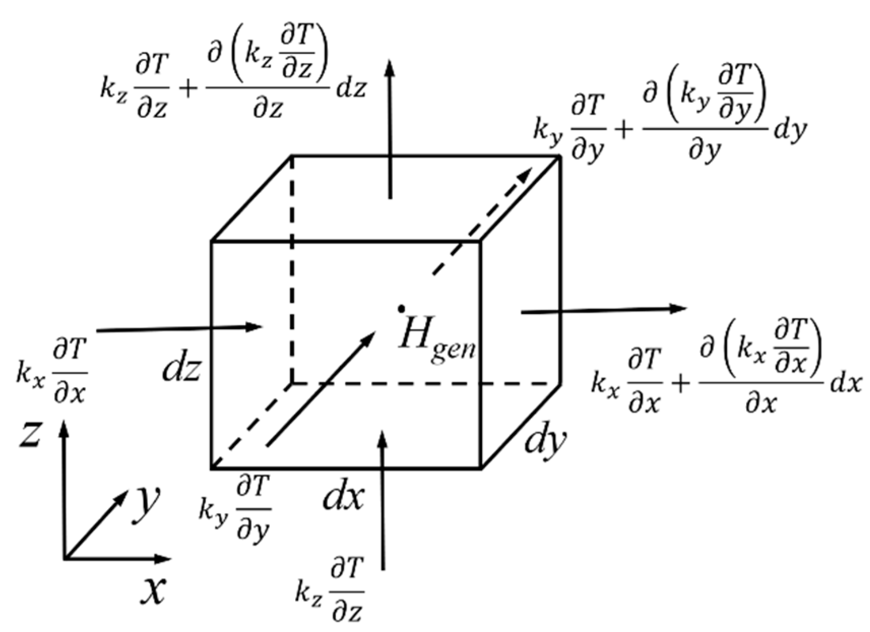
  • Unlike single-sided welding, there is a dual heat source in double-sided welding. In order to reduce the difficulty of constructing the temperature field of dual heat sources and reduce the amount of calculation in thermal deformation optimization, an inherent strain method with a welding deformation prediction function is introduced in this paper. Based on the analysis of the welding deformation formation mechanism under the double-sided welding process, the calculation methods of the longitudinal shrinkage deformation and the transverse shrinkage deformation for the base metal after double-sided welding are determined, which provides a basis for the global and distributed intelligent optimization of the double-sided welding sequence.
  • Aiming at the multi-variable optimization requirements of the double-sided welding sequence, a double-sided welding sequence optimization model for the purpose of reducing the welding deformation is constructed first by constructing the deformation calculation based on the inherent strain method, and under the boundary constraints of the weldment. Then, an immune clonal optimization algorithm based on similar antibody similarity screening and steady-state adjustment is introduced, and the double-sided welding sequence immune optimization process is designed, which enables the welding sequence optimization with distributed and global optimization capabilities.
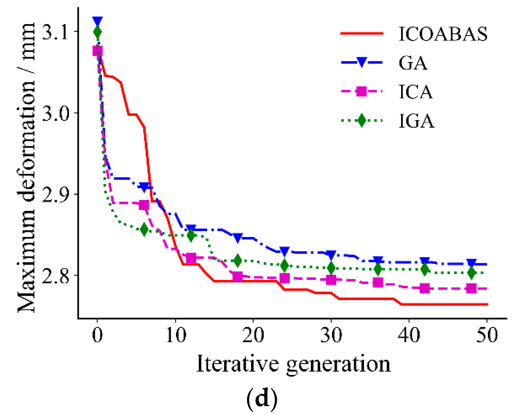
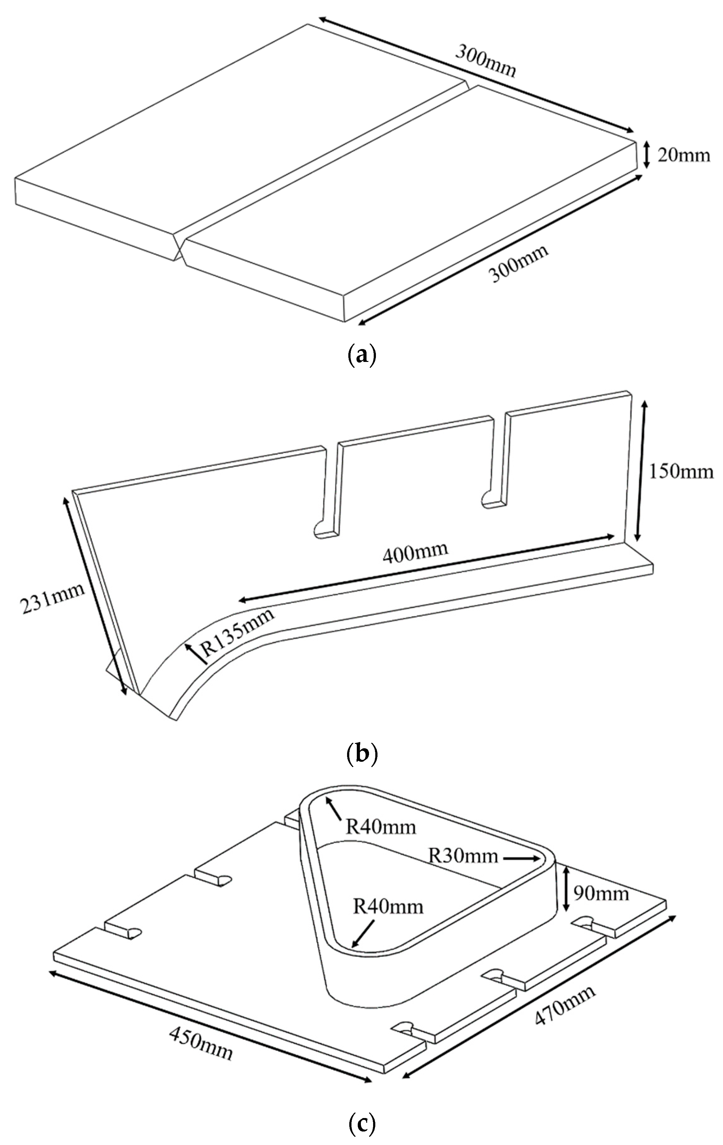
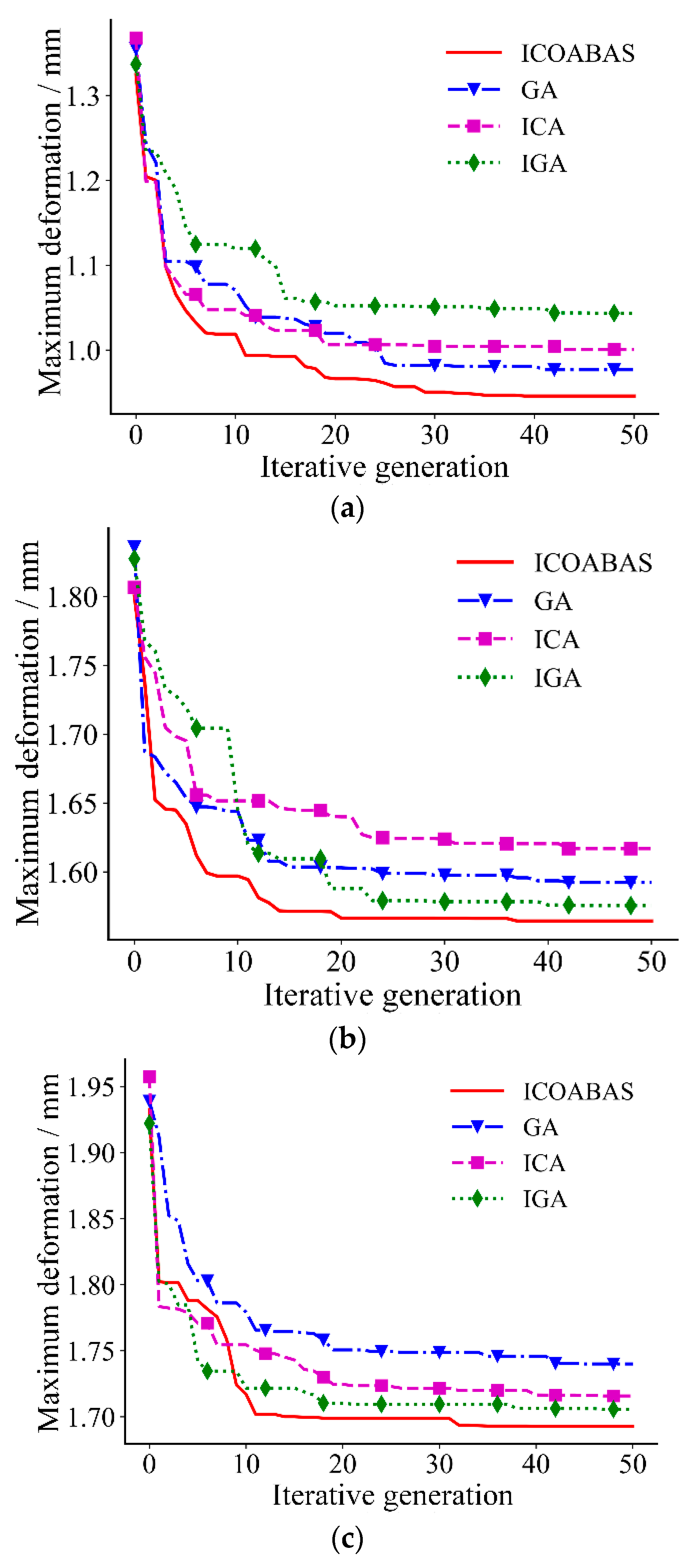
  • The numerical test results of four kinds of ship welding parts show that compared with other intelligent algorithms, the maximum welding deformation caused by the proposed algorithm is reduced by 2.4%, 2.8%, and 3.3%, respectively, the average maximum welding deformation is reduced by 2.6%, 2.5%, and 3.4%, respectively, and the convergence generation is reduced by 16.2%, 13.4%, and 11.2%, respectively, which verifies that the proposed immune clonal optimization algorithm is characterized by strong optimization ability and high optimization efficiency in the double-sided welding sequence. This is mainly because the vaccine extraction and vaccination operator of ICOABAS realizes the uniform distribution of the solution space, which improves the global search ability of the algorithm, and the population replenishment operator of ICOABAS realizes population diversity by updating similar antibodies in the population, which improves the search efficiency of the algorithm. Moreover, The experimental test results show that, compared with the traditional continuous welding, the deformation caused by the optimized welding sequence is reduced by 32.9%, which further verifies the effectiveness of the double-sided welding sequence based on the proposed ICOABAS in effectively reducing welding deformation.
Aiming at the selection of double-sided welding sequences for medium-small assemblies in ships, immune optimization is carried out in this paper, and the effectiveness is verified by numerical tests and experiments. However, both the numerical test and the experimental test are completed in ideal environments, and there is a certain gap between them and the actual ship welding site. In order to verify the effectiveness of the proposed immune optimization for the double-sided welding sequence, the next step of this research is to apply the results to the ship construction site and further verify their effectiveness through field tests and applications.

Author Contributions

Methodology, Y.S. and S.L.; validation, M.Y., S.L. and J.L.; original draft preparation, M.Y. and S.L.; writing, S.L. and X.D. All authors have read and agreed to the published version of the manuscript.

Funding

This research was funded by the High-Tech Ship Scientific Research Project from the Ministry of Industry and Information Technology ([2019]360), and the 2021 Industry-University Research Preresearch Fund Project of Zhangjiagang City (ZKCXY2138).

Institutional Review Board Statement

Not applicable.

Informed Consent Statement

Not applicable.

Data Availability Statement

Not applicable.

Conflicts of Interest

The authors declare no conflict of interest.

References

  1. Jin, T. Analysis of single-side welding process and defects of CO2 ceramic liner. MW Metal Form. 2017, 14, 81–83. [Google Scholar] [CrossRef]
  2. Wang, L.J.; Zhang, Q.; Chen, J.P.; Qin, M.; Wang, Z.J. Development and application of double-sided synchronous submerged arc welding technology for large storage tanks. Weld. Technol. 2010, 39, 34–37. [Google Scholar] [CrossRef]
  3. Li, Q.; Wang, Y.S.; Zhao, L.H.; Liu, N.N. Study on residual stress and deformation of single and double-side welding structure of T plates. Hot Work. Technol. 2017, 46, 197–201. [Google Scholar] [CrossRef]
  4. Chen, D.G.; Liu, J.H.; Chen, D.L. Properties of welded joints of 7A52 aluminum alloy thick-plate by single-side and double-side friction stir welding. Ordn. Mater. Sci. Eng. 2016, 39, 29–31. [Google Scholar] [CrossRef]
  5. Tang, J.X.; Wu, M.X.; Shi, L.; Wu, C.S.; Yang, W. Pure aluminum/T2 copper dissimilar metal double-sided friction stir weld formation and mechanical properties. Chin. J. Nonf. Metals 2022, 2, 1–15. [Google Scholar] [CrossRef]
  6. Sun, J.T.; Li, X.Y.; Zhang, L.; Yan, W.T.; Yang, Q.Z. Performance of a new aluminum alloy joint with butt-weld. Rare Metal Mater. Eng. 2017, 46, 2607–2612. [Google Scholar]
  7. Sun, W. Application of submerged arc double-sided welding in circumferential seam welding of large storage tanks. Petrol. Chem. Const. 2019, 41, 71–72. [Google Scholar] [CrossRef]
  8. Zhou, Y.B.; Shi, W.Q. Development of double arc high efficiency welding technology. Elec. Weld. Mach. 2019, 49, 44–51. [Google Scholar] [CrossRef]
  9. Liu, Y.X.; Li, Z.L.; Chen, H.; Yang, D.F.; Gao, Y.H.; Chen, C.; Chi, S.J. Numerical simulation prediction of residual stress distribution of volute-seat ring welds under different welding sequence. Hot Work. Technol. 2020, 49, 125–128. [Google Scholar] [CrossRef]
  10. Liu, Y.; Jiang, B.; Wang, H.Z.; An, B.; Yang, X.H. Influence of welding sequence on welding residual stress and deformation of lateral stop. J. Mech. Eng. 2019, 55, 57–65. [Google Scholar] [CrossRef]
  11. Luo, J.Y.; Zuo, J.; Zhang, J.H. Evaluation of welding residual stress and welding path optimization of square steel T-type joint for frame. Hot Work. Technol. 2021, 50, 112–117. [Google Scholar] [CrossRef]
  12. Tang, Q.; Liu, Z.; Chen, P.; Chen, H.; Yang, T. Numerical simulation of welding deformation of subway bolster based on inherent strain method. Hot Work. Technol. 2019, 48, 128–130. [Google Scholar] [CrossRef]
  13. Xiang, L.; Ye, F.; Liang, X.; Ou, Y.A.H.; Zhao, N.L. Multi-tube freezing temperature field considering range of influence of freezing tubes. Tun. Const. 2021, 41, 52–59. [Google Scholar] [CrossRef]
  14. Wang, C.; Wu, C.B.; Shao, L.T. Development of elastic finite element model for predicting welding deformation based on artificial thermal strain method. J. Mech. Eng. 2022, 37, 111–119. [Google Scholar] [CrossRef]
  15. Qu, R.B.; Guo, Y.F.; Xu, S.K. Optimization analysis of welding sequence of ballast water filter cartridge support. MW Metal Form. 2021, 9, 74–77. [Google Scholar] [CrossRef]
  16. Huang, Y.; Ma, W.T.; Zhang, H.M.; Yu, S.L.; Pan, J.R. Numerical simulation and deformation study on temperature field of laser cladding repair process for slender shaft parts. Mech. Elec. Equip. 2017, 34, 28–34. [Google Scholar] [CrossRef]
  17. Saida, I.; Wakrim, L.; Hassani, M.M. Nonuniform semi-patches for designing an ultra wideband PIFA antenna by using genetic algorithm optimization. Wirel. Pers. Commun. 2021, 117, 957–969. [Google Scholar] [CrossRef]
  18. Du, A.; Chen, Y.; Zhang, D.; Han, Y. Multi-objective energy management strategy based on PSO optimization for power-split hybrid electric vehicles. Energies 2021, 14, 2438. [Google Scholar] [CrossRef]
  19. Kamarposhti, M.A.; Colak, I.; Iwendi, C.; Band, S.S.; Ibeke, E. Optimal coordination of PSS and SSSC controllers in power system using ant colony optimization algorithm. J. Circuit. Syst. Comp. 2022, 31, 2250060. [Google Scholar] [CrossRef]
  20. Arneth, B. Comparison of Burnet’s clonal selection theory with tumor cell-clone development. J. Theranostics 2018, 8, 3392–3399. [Google Scholar] [CrossRef]
  21. Xue, C.G.; Dong, L.L.; Li, G.H. An Improved Immune Genetic Algorithm for the Optimization of Enterprise Information System based on Time Property. J. Softw. 2011, 6, 436–443. [Google Scholar] [CrossRef]
  22. Liu, S.D.; Tao, L.J.; Liu, C.; Gao, Y.Q.; Sun, H.W.; Yuan, M.X. Immune Cloning Optimization Algorithm Based on Antibody Similarity Screening and Steady-State Adjustment. In Proceedings of the Name of the 2021 3rd International Conference on Advanced Information Science and System, Sanya, China, 26–28 November 2021; pp. 355–359. Available online: https://camps.aptaracorp.com/AuthorDashboard/dashboard.html?key=0&val=68b639ba-5286-11ec-b613 (accessed on 2 March 2022).
  23. Zeng, S.Y. Optimization algorithm for power flow calculation of power system considering power spring. Int. J. Sci. 2020, 7, 23–28. [Google Scholar]
  24. Yang, W.X.; Chen, Z.; Li, C.J. Adaptive clone selection algorithm for function optimization. Appl. Mech. Mater. 2014, 3468, 2147–2150. [Google Scholar] [CrossRef]
  25. Qu, H.Y.; Cheng, S.N. A new neural network with genetic algorithm in searching nonlinear function extremum. J. Phys. Conf. Ser. 2021, 1732, 12085–12086. [Google Scholar] [CrossRef]
  26. Liu, J.; He, G.Z.; Qu, Z.J. Research on double-sided welding process of 84 mm thick 6082 aluminum alloy profile by friction stir welding. Weld. Technol. 2018, 47, 148–150. [Google Scholar] [CrossRef]
Figure 1. The stress distribution on the heated surface of the base metal element.
Metals 12 01091 g001
Figure 2. Schematic diagram of double-sided welding of welding robot.
Metals 12 01091 g002
Figure 3. The temperature change of the heated surface of the base metal unit.
Metals 12 01091 g003
Figure 4. Flow of the basic immune clonal optimization algorithm.
Metals 12 01091 g004
Figure 5. Four types of ship welded structures: (a) welded structure 1; (b) welded structure 2; (c) welded structure 3; (d) welded structure 4.
Metals 12 01091 g005aMetals 12 01091 g005b
Figure 6. Coding of welding seams for four welded structures: (a) welded structure 1; (b) welded structure 2; (c) welded structure 3; (d) welded structure 4.
Metals 12 01091 g006
Figure 7. Evolution curves of maximum deformation from four algorithms in four structures: (a) welded structure 1; (b) welded structure 2; (c) welded structure 3; (d) welded structure 4.
Metals 12 01091 g007aMetals 12 01091 g007b
Figure 8. Deformation of welded structure 1 under the welding sequence of “④⑤③⑥②⑦①⑧”: (a) total deformation cloud map; (b) deformation cloud map along the x-axis; (c) deformation cloud map along the z-axis.
Metals 12 01091 g008aMetals 12 01091 g008b
Figure 9. Deformation of welded structure 2 under the welding sequence of “④⑤③⑥②①⑦⑧”: (a) total deformation cloud map; (b) deformation cloud map along the x-axis; (c) deformation cloud map along the z-axis.
Metals 12 01091 g009
Figure 10. Deformation of welded structure 3 under the welding sequence of “⑤⑦④⑧②①③⑨⑥”: (a) total deformation cloud map; (b) deformation cloud map along the x-axis; (c) deformation cloud map along the z-axis.
Metals 12 01091 g010aMetals 12 01091 g010b
Figure 11. Deformation of welded structure 4 under the welding sequence of “①⑦③⑨②⑧④⑥⑤”: (a) total deformation cloud map; (b) deformation cloud map along the x-axis; (c) deformation cloud map along the z-axis.
Metals 12 01091 g011aMetals 12 01091 g011b
Figure 12. S-shaped weldment.
Metals 12 01091 g012
Figure 13. QJRH4-1A welding robot.
Metals 12 01091 g013
Figure 14. Coding of S-shaped weldment.
Metals 12 01091 g014
Figure 15. Welded product under the welding sequence “①②③④⑤⑥”: (a) front view; (b) reverse view.
Metals 12 01091 g015
Figure 16. The point cloud data of the weldment under the welding sequence “①②③④⑤⑥”: (a) before welding; (b) after welding.
Metals 12 01091 g016
Figure 17. Contour comparison curves under welding sequence “①②③④⑤⑥”.
Metals 12 01091 g017
Figure 18. Welded product under the welding sequence “②④③⑤①⑥”: (a) front view; (b) reverse view.
Metals 12 01091 g018
Figure 19. The point cloud data of the weldment under the welding sequence “②④③⑤①⑥”: (a) before welding; (b) after welding.
Metals 12 01091 g019aMetals 12 01091 g019b
Figure 20. Contour comparison curves under welding sequence “②④③⑤①⑥”.
Metals 12 01091 g020
Figure 21. Welded product under the welding sequence “③④②⑤①⑥”: (a) front view; (b) reverse view.
Metals 12 01091 g021
Figure 22. The point cloud data of the weldment under the welding sequence “③④②⑤①⑥”: (a) before welding; (b) after welding.
Metals 12 01091 g022
Figure 23. Contour comparison curves under welding sequence “③④②⑤①⑥”.
Metals 12 01091 g023
Table 1. Changes in the mechanical properties of the welding base metal at different temperatures [15].
Temperature/°CMechanical Properties
Yield Strength/MPaElastic Modulus
/GPa
Poisson’s RatioConvection Coefficient/W·(m2·K)−1
253452060.2823
250270187
500220150
750160120
10007570
15002010
Temperature/°CLinear Expansion CoefficientSpecific
Heat Capacity/J·(kg·°C)−1
Thermal Conductivity/W·(m·K)−1
251.30 × 10−546044
2501.32 × 10−548039
5001.39 × 10−553033
7501.48 × 10−567530
10001.34 × 10−567026
15001.33 × 10−570020
Table 2. Test results of four optimization algorithms for four welded structures.
AlgorithmICOABASGA
Structure 1Maximum deformation/mm0.9460.977
Average maximum deformation/mm0.8890.927
Convergence generation3741
Optimal welding sequence④⑤③⑥
②⑦①⑧
⑤④③⑥
②⑦①⑧
Structure 2Maximum deformation/mm1.5641.592
Average maximum deformation/mm1.4851.516
Convergence generation3642
Optimal welding sequence④⑤③⑥
②①⑦⑧
②④⑥①
③⑤⑦⑧
Structure 3Maximum deformation/mm1.6931.740
Average maximum deformation/mm1.6161.667
Convergence generation3341
Optimal welding sequence⑤⑦④⑧
②①③⑨⑥
⑤⑧④⑦
②①③⑥⑨
Structure 4Maximum deformation/mm2.7642.814
Average maximum deformation/mm2.7212.750
Convergence generation3843
Optimal welding sequence①⑦③⑨
②⑧④⑥⑤
①⑨③⑦
④⑥②⑧⑤
AlgorithmICAIGA
Structure 1Maximum deformation/mm1.0011.044
Average maximum deformation/mm0.9320.983
Convergence generation4241
Optimal welding sequence②④⑥③
⑤⑦①⑧
④⑤②⑦
③⑥①⑧
Structure 2Maximum deformation/mm1.6171.576
Average maximum deformation/mm1.5431.516
Convergence generation4140
Optimal welding sequence④⑤③⑥
②⑦①⑧
②④⑥③
⑤⑦①⑧
Structure 3Maximum deformation/mm1.7161.706
Average maximum deformation/mm1.6371.624
Convergence generation3937
Optimal welding sequence ①②④⑧
⑤⑦③⑨⑥
⑤⑦②①
④⑧③⑨⑥
Structure 4Maximum deformation/mm2.7842.803
Average maximum deformation/mm2.7172.729
Convergence generation4142
Optimal welding sequence①③⑦⑨
④⑥②⑤⑧
①⑦④③
⑨⑥②⑧⑤
Table 3. Welding deformation under different welding sequences.
Welding SequenceMaximum Deformation (mm)
①②③④⑤⑥0.76
②④③⑤①⑥0.51
③④②⑤①⑥0.70
Publisher’s Note: MDPI stays neutral with regard to jurisdictional claims in published maps and institutional affiliations.

