Article

Preferential Locations of Hydrogen Accumulation and Damage in 1.2 GPa and 1.8 GPa Grade Hot-Stamped Steels: A Comparative Study

1
School of Material Engineering, Jinling Institute of Technology, Nanjing 211169, China
2
Technology Center, Maanshan Iron & Steel Co., Ltd., Maanshan 243001, China
3
School of Materials Science and Engineering, Anhui University of Technology, Maanshan 243002, China
*
Author to whom correspondence should be addressed.
Metals 2022, 12(7), 1075; https://doi.org/10.3390/met12071075
Submission received: 6 May 2022 / Revised: 12 June 2022 / Accepted: 21 June 2022 / Published: 23 June 2022

Abstract

:
In this work, hydrogen segregation and damage sites in 1.2 GPa and 1.8 GPa grade hot-stamped steels were comparatively investigated by hydrogen permeation experiments and the hydrogen microprint technique (HMT). Compared with 1.2 GPa steel, 1.8 GPa steel exhibited a lower hydrogen diffusion coefficient (Deff) and a higher number of hydrogen trapping sites (Nt) due to its finer microstructure and richer nano-sized precipitates. The results of HMT showed that the grain boundaries in both steels played a role in initial hydrogen segregation, and then the martensitic laths became the locations of hydrogen accumulation. For 1.2 GPa and 1.8 GPa steels, however, hydrogen accumulation appeared preferentially on martensitic laths and grain boundaries, respectively, resulting in various damage behaviors. The introduced nano-sized carbides as “good hydrogen traps” played an important role in hydrogen diffusion, accumulation, and damage, which greatly alleviated hydrogen-induced cracking for the 1.8 GPa steel. Moreover, electron backscatter diffraction (EBSD) analysis further revealed that the damage behavior was also controlled by the low-angle grain boundary, stress distribution, and recrystallization fraction of the samples.

1. Introduction

Hot stamping is one of the widely used technologies for producing automotive parts, such as A- and B-pillars, which can provide them with high strength and excellent formability [1,2,3]. To take the Volvo XC90 as an example, over 38% of auto parts are manufactured by hot stamping, which not only reduces the weight but also improves the safety of the automobile [4]. Recently, 1.8 GPa grade hot-stamped steels have also been developed by increasing the carbon content and introducing beneficial precipitates [5]. However, hydrogen embrittlement (HE) is a severe challenge for hot-stamped steels with a high tensile strength of >1.2 GPa due to their high susceptibility to hydrogen. Therefore, numerous studies have been conducted to prevent HE of the steels, such as by controlling the size and number of inclusions [6], introducing irreversible hydrogen traps [7,8], and adding micro-alloying elements [9,10]. One of the most promising methods is to produce nano-sized precipitates by adding carbide formers [11]. These carbides not only reduce the HE susceptibility by introducing effective hydrogen traps but also induce precipitation strengthening. In the study reported by Lin et al. [12], precipitates of Nb(C,N) led to a reduction in hydrogen diffusion. Turk et al. [13] investigated the hydrogen trapping capacity of VC and found that carbides of 10 nm firmly trapped more hydrogen. These studies clearly indicate that effective traps can remarkably improve the HE resistance of 22MnB5.
So far, many HE mechanisms have been proposed to explain HE phenomena, including the hydrogen pressure theory (HP), hydrogen-enhanced localized plasticity mechanism (HELP), and hydrogen-enhanced decohesion mechanism (HEDE). However, there is still no commonly accepted mechanism to explain all HE occurrences involving hydrogen diffusion and accumulation that are associated with high internal strain and hydrogen traps such as grain boundaries, dislocations, precipitates, vacancies, etc. Thomas et al. [14] confirmed that the intensity of hydrogen diffusion gradually increased from grains, grain boundaries, triple junctions, and cementites in X70 pipeline steel by using the hydrogen microprint technique (HMT). Chen et al. [15] found that the lattice diffusion of the ferrite phase in duplex stainless steel promoted the migration of hydrogen atoms by using HMT. Koji et al. [16] investigated the hydrogen diffusion and distribution in ferrite and pearlite by HMT. Okayasu et al. [17] reported that HE is related to the amount of hydrogen at the grain boundary and martensitic lath boundary, and high internal strain and/or high dislocation density could lead to accelerated hydrogen damage in 22MnB5 steel. So far, the specific hydrogen diffusion and accumulation in lath and grain boundaries have not been elucidated. To understand the intrinsic HE of ultra-high-strength hot-stamping steels, the hydrogen trap and stress level effects on hydrogen diffusion and accumulation should be clearly ascertained.
In this study, we systematically investigated the hydrogen accumulation and damage of 1.2 GPa and 1.8 GPa grade hot-stamped steels, and the hydrogen diffusion behavior was measured by hydrogen permeation experiments. In addition, hydrogen diffusion and accumulation sites were characterized by HMT, and the microstructure was analyzed by optical microscopy (OM) and transmission electron microscopy (TEM). Finally, EBSD (electron backscatter diffraction) analysis further revealed the damage behavior.

2. Experimental Procedures

2.1. Materials and Heat Treatments

In this study, 1.2 GPa and 1.8 GPa steels are named A-1200 and A-1800 steels, respectively. Their chemical compositions are shown in Table 1. A reference steel not containing Nb, V, or Ti is a typical “Base (A-1200)” steel, and Nb, V, or Ti was added to this “Base” steel to produce “A-1800” steel. They were melted in a vacuum-induction furnace by Ma’anshan Iron and Steel Co., Ltd (Maanshan, China). The melts were first cast into thick plates, heated to 1230 °C for 2 h, and then rolled to a thickness of 3 mm. After rolling, the steel sheets were annealed at 670 °C for 24 h and finally cooled down to room temperature in the furnace. To simulate automobile steel, the as-annealed A-1200 and A-1800 sheets were austenitized at 930 °C for 240 s and then immediately transferred to a heat-resistant steel die. The sheets were finally quickly stamped to plates with a size of 100 × 100 × 1.5 mm3 and then water-quenched to room temperature.

2.2. Microstructural Characterization

The microstructure was observed by OM and scanning electron microscopy (SEM, Tescan MIRA3-XMU; TESCAN Inc., Burno, Czech Republic). To reveal the size of prior austenite grains, the specimens were polished and etched in a solution (50 mL of saturated picric acid solution + 2 g of sodium dodecyl benzene sulfonate + 0.5 mL of hydrochloric acid) at 85 °C. To detect precipitates, the thin foils were examined with a JEM-2010 high-resolution transmission microscope (HRTEM) (JEOL Inc., Tokyo, Japan) operated at 200 kV. Moreover, EBSD analysis was conducted by using a MAIA3 XMH scanning electron microscope (TESCAN Inc., Burno, Czech Republic) at 20 kV (step size, 0.12 μm; electron beam intensity, 20 μA).

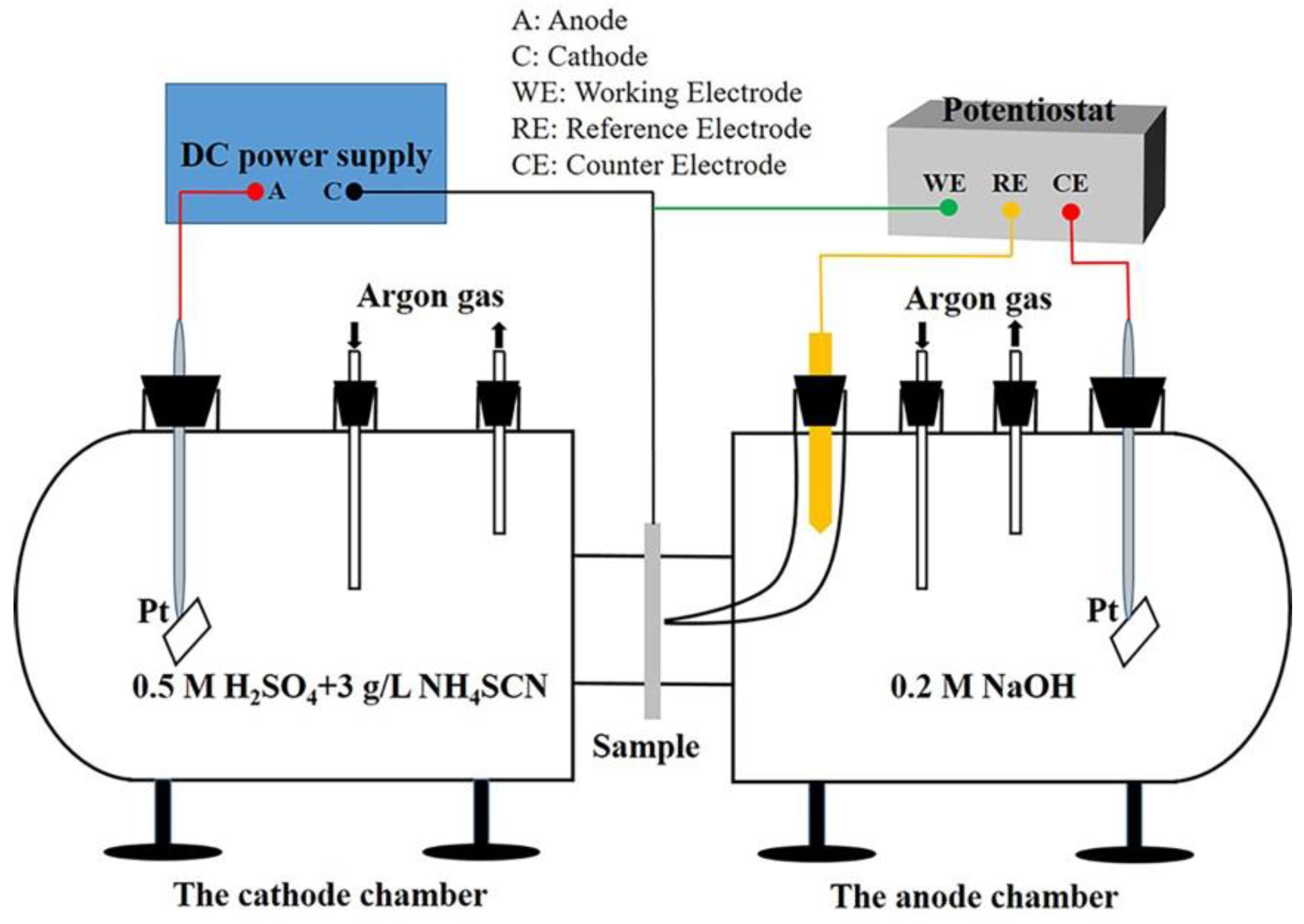
2.3. Hydrogen Permeation Test

To understand hydrogen diffusion behavior, a modified Devanathan–Stachurski cell (It is a homemade device) [18] was used for the hydrogen permeation test. A schematic diagram of the hydrogen permeation test apparatus is presented in Figure 1. The D-S cell contains two parts: the cathode chamber (source of hydrogen) and the anode chamber (diffused hydrogen and creation of a proportional current). They were separated by samples with a size of 25 × 25 × 1.5 mm3, which were polished on either side before the test to eliminate the effect of surface adsorption. The electrolyte of the anode chamber was 0.2 M NaOH, and the surface area of the specimen in contact with the electrolyte was 1.766 cm2. A constant potential of 0.2 V was applied to the anode chamber to oxidize the hydrogen atoms. Subsequently, a background current that decreased with time could be observed. When the background current decreased to a value below 1 μA, a mixed electrolyte of 0.5 M H2SO4 and 3 g/L NH4SCN was poured into the cathode chamber. Thereafter, a constant current of 25 mA/cm2 was provided to the cathode chamber by a DC power supply.
The effective hydrogen diffusion coefficient Deff (cm2/s) can be calculated by using the time lag method [19].
D eff = L 2 / 6 t L
where L is the thickness of the sample, and tL is the lag time, defined as 0.63 times the steady-state current.
The density of reversible and irreversible hydrogen traps in the sample was measured by using the two-step polarization method; i.e., the second hydrogen charging again started when the first steady-current decreased to below 1 μA. Moreover, parameters such as permeability (JL) and apparent hydrogen solubility (Capp) can be calculated by the following equations [20,21,22].
J L = I L / FA
C app   = J L / D eff
N t   = nC app ( D l / D eff - 1 ) / 3
N ir   = N t - N r
In the relations listed above, I (μA), F (C/mol), and A (cm2) are the steady-state current, Faraday’s constant, area of the specimen, and lattice diffusion coefficient in α-Fe (Dl =1.28 × 10⁻⁴ cm2/s) [14,20], respectively. The number of electrons transferred in each mole is n, and it is taken as 6.02 × 10²³ e/mol [14]. Nir, Nt, and Nr are the irreversible hydrogen trapping sites, the first permeation hydrogen trapping sites, and the second permeation (reversible) hydrogen trapping sites, respectively.

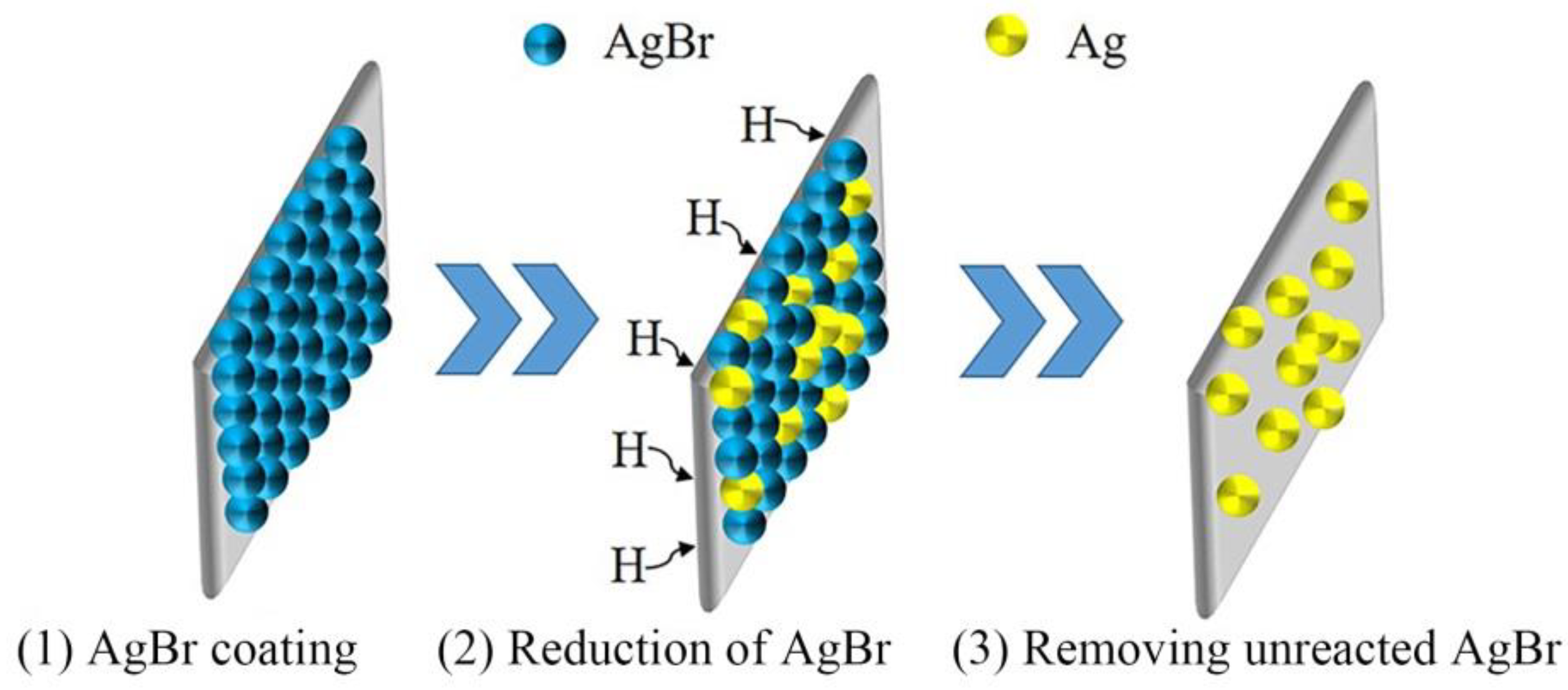
2.4. Hydrogen Microprint Technique (HMT)

HMT, as shown in Figure 2, is an effective characterization method for hydrogen diffusion paths in steels [23,24]. The preparation of the sample is the same as that for the electrochemical test. To reveal the relations between hydrogen diffusion and the microstructure, the hydrogen charging surface of the sample needs to be etched before the test. The etched samples were charged at a current density of 5 mA/cm2 for 20, 60, 90, or 120 min. The charged sample was removed within 1 min, and subsequently, the emulsion (1 g of silver bromide and 2 mL of 1.4 M sodium nitrite solution) was coated onto the etched surface in a darkroom for the hydrogen reduction of the silver ions to metallic silver according to Equation (6).
Ag + + H = Ag + H +
To wash off the remaining unreacted emulsion, the surfaces were dipped into a mixed solution containing 0.6 M sodium thiosulfate solution and 1.4 M sodium nitrite solution for 7 min. Then, the surfaces were cleaned three times using distilled water. Eventually, white spherical particles superimposed on the microstructure could be observed by SEM.

3. Results and Discussion

3.1. Hydrogen Diffusion Behaviors and Traps

Figure 3 shows the hydrogen permeation curves of A-1200 and A-1800 steels. It can be seen that the curves have two distinct polarization steady-state current (Ia) values for both steels, in which the first one is higher than the second one. This can be attributed to both reversible and irreversible hydrogen trapping sites being involved and saturated during the first hydrogen charging, while only the reversible traps are involved in the second one [14,15,25]. The calculated hydrogen permeation parameters are listed in Table 2. The hydrogen trapping sites (Nt) were determined to be 1.29 × 10²¹ and 1.59 × 1021 cm−3 for A-1200 and A-1800 steels, respectively. Traps can reduce the mobile ability of hydrogen; thus, A-1800 steel exhibits a lower hydrogen diffusion coefficient (Deff). Owing to the elimination of the strong effect of the saturated irreversible traps, the second value of Deff is reasonably higher than the first one for both steels. Significantly, the irreversible hydrogen trapping sites (Nir) were approximately two times higher in A-1800 steel than that in A-1200 steel.
Because the high Nir value must be linked to the microstructure, TEM micrographs of A-1200 and A-1800 steels are compared to those shown in Figure 4. It can be seen that a fully lath martensite structure is achieved in both steels after hot stamping. However, the average widths of the laths are about 370 and 200 nm for A-1200 and A-1800 steels, respectively (see Figure 4a,c). This indicates that more substructures considered as hydrogen traps could be achieved in A-1800 steel. Figure 4b further shows the high-density dislocation tangles present in the laths of A-1200 steel. In addition to the high-density dislocations, abundant precipitates (indicated by black arrows) with a size of 2~10 nm were found to be uniformly dispersed near the dislocations (indicated by red arrows) in A-1800 steel, which were further revealed to be nano-sized (Nb, V, Ti)C by energy-dispersive X-ray spectrometry (EDX) (see Figure 4d,e). The formation of carbides is directly associated with the increased carbon and the introduced micro-alloying elements (see Table 1), which also strongly improved the strength of steel to 1.8 GPa. Previous studies have indicated that carbides, such as nano-sized NbC, VC, and TiC, are often identified as “good irreversible straps” with high hydrogen binding energy (Eb > 60 kJ mol−1 H), decrease hydrogen diffusivity and increase critical hydrogen concentration in steel, leading to enhanced resistance to HE [26]. Therefore, reduced hydrogen damage is expected for A-1800 steel. In fact, damages often originate in hydrogen accumulation sites. Thus, the process of segregation was further investigated by HMT, as described in the following section.

3.2. Locations of Hydrogen Accumulation

Figure 5 displays SEM micrographs of the HMT test specimen surfaces of both steels, in which HMT produced observable white silver particles correlated to the location of hydrogen. As shown in Figure 5a, a few silver particles seem to vaguely emerge in the grain boundaries of the A-1200 sample charged for 20 min. When increasing the charging time to 60 min, it can be clearly seen that the silver particles are distributed along the grain boundaries (see Figure 5b). The investigations tangibly demonstrate that the grain boundary acts as an initial location of hydrogen segregation due to its weak trapping ability. Compared with A-1200 steel, the lag in hydrogen diffusion and accumulation can be confirmed for the A-1800 samples, which is consistent with the results of hydrogen permeation. For example, negligible silver particles were found on the surface of the sample charged for 20 min (see Figure 5e). Clearly, Figure 5c shows that hydrogen diffused from the grain boundary to the grain interior and partially clustered in laths for the A-1200 sample charged for 90 min. However, this phenomenon was very rarely detected in the A-1800 sample charged for 90 min. Although both steels exhibited the initial hydrogen segregation in the grain boundary, their differences can be further identified from their comparison as follows: (i) noticeably alleviated hydrogen aggregation was achieved for A-1800 steel charged for 120 min (see Figure 5d,h); (ii) the preferential sites of hydrogen aggregation were determined to be lath and grain boundaries for A-1200 and A-1800 steels, respectively (see Figure 6).
Wang et al. [27] reported that the grain boundary promoted hydrogen diffusion and formed a short-circuit diffusion path. In fact, plenty of reports have confirmed that the role of the grain boundary strongly depends on its trap binding energy; i.e., a low-angle grain boundary (LAGB, angle misorientation θ < 15°) has higher binding energy than a high-angle one (HAGB, θ > 15°) and results in relatively difficult hydrogen diffusion, even acting as an obstacle [28]. Figure 7a,b compare the grain sizes of A-1200 and A-1800 steels. The linear intercept method was used to estimate their average grain sizes of 23.65 ± 0.32 μm and 7.59 ± 0.27 μm, respectively. The refinement of grains can be attributed to the addition of Ti + Nb + V; their nano-sized carbides pinned the movement of the grain boundary during hot stamping. Figure 7c,d show the EBSD maps of A-1200 and A-1800 samples, and their misorientation distribution and statistical LAGB area fraction are further shown in Figure 7e,f. It was found that the LAGB area fractions were 24.35% and 35.34% for A-1200 and A-1800, respectively. In general, the HAGBs provide diffusion channels to obtain high permeability (JL) and apparent hydrogen solubility (Capp) [29,30]. This indicates that the low JL and Capp of A-1800 steel (see Table 2) relate to the high LAGB area fraction, resulting in fewer hydrogen atoms reaching the hydrogen discharging surface. Moreover, the increased grain boundary area caused by refinement also reduces the hydrogen concentration per unit area. On the other hand, abundant nano-sized carbides were uniformly achieved in laths of A-1800 steel. These “good irreversible straps” play a vital role in sluggish hydrogen diffusion and alleviative hydrogen accumulation in laths. The various accumulation behaviors imply different hydrogen damage characteristics, and thus, hydrogen-induced crack initiation and propagation were further investigated for both steels.

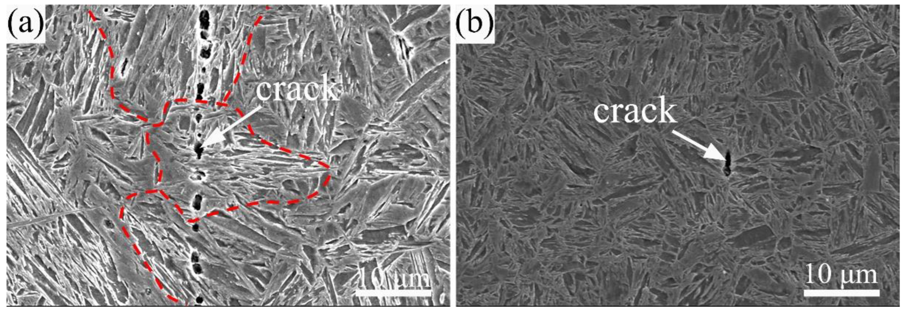
3.3. Hydrogen-Induced Crack Initiation and Propagation Behaviors

To evaluate the resistance to hydrogen damage, the samples were charged at a current density of 50 mA/cm2 for 24 h. Table 3 lists the features of the observed cracks on surfaces with a size of 25 × 25 mm2 according to SEM. Compared with the A-1200 sample, a greatly decreased number, length, and width of cracks were achieved for the A-1800 sample. Besides the remarkably alleviated HE, different preferential initiation sites and propagation methods of cracks were observed for the A-1800 sample. Figure 8 shows representative SEM images of hydrogen-induced cracks in the samples. It can be seen that a severe, long transgranular crack was induced in the A-1200 sample. Clearly, the long crack consists of multiple short micro-cracks initiated in laths. As shown in Figure 8b, however, the A-1800 sample shows a short crack initiated in the triple junction of grain boundaries and propagated along with it. This indicates that the hydrogen-induced crack initiation and propagation behaviors are closely related to the site and level of hydrogen accumulation.
The kernel average misorientation (KAM) maps of both samples are shown in Figure 9. The KAM map is routinely used to determine the dislocation density and stress status of the material. Figure 9 clearly demonstrates that A-1200 steel has a higher dislocation density and internal stress than A-1800 steel. This result is consistent with our previous investigation on micro-alloyed steel [9]. The structural transformation during hot stamping is a complex process involving deformation, recovery, recrystallization, phase transformation, etc. The EBSD recrystallization maps shown in Figure 10 further reveal that incomplete recrystallization was achieved in both steels due to the short stamping time (10 s). The dual effects of deformation and martensitic transformation caused a large number of dislocations and high internal stress in laths, resulting in fast hydrogen diffusion and accumulation in the grain interior due to their role as reversible hydrogen traps [10]. The higher number of reversible trap sites (Nr) (see Table 2) must be responsible for the preferential hydrogen accumulation on laths for A-1200 steel. The HELP mechanism revealed that hydrogen can bring about dislocation mobility, pile-up, and H-dislocation Cottrell atmospheres, which is the direct cause of the formation of hydrogen-induced micro-cracks [31,32]. Micro-cracks initiated in laths and severe transgranular cracks were also found in the A-1200 sample. Figure 10 shows that A-1800 steel had a higher recrystallization fraction than A-1200 steel. This caused the relatively low dislocation density and internal stress (see Figure 9), which must be responsible for the great suppression of hydrogen damage in A-1800 steel. In particular, nano-sized carbides as “good hydrogen traps” alleviated hydrogen accumulation in laths and reduced H-dislocation Cottrell atmospheres in the grain interior. On the other hand, these dispersive carbides, such as NbC, VC, and TiC, can pin H-dislocations and impede their mobility during hydrogen charging [33,34]. Thus, the HELP process was remarkably mitigated in the grain interior for A-1800 steel. Moreover, higher precipitation strengthening was obtained in laths, so the grain boundary strength was lower than that of the matrix. The aggregated hydrogen near the grain boundary (see Figure 6) drove dislocations to move and pile on the triple junction, resulting in the nucleation and growth of micro-cracks in A-1800 steel.

4. Conclusions

In this study, the preferential locations of hydrogen accumulation and damage in A-1200 and A-1800 steels were investigated by electrochemical hydrogen permeation experiments and HMT. The relations between hydrogen diffusion behavior, segregation, damage, and microstructure were systematically analyzed by OM, TEM, and EBSD analysis. The obtained results can be summarized as follows:
(1)
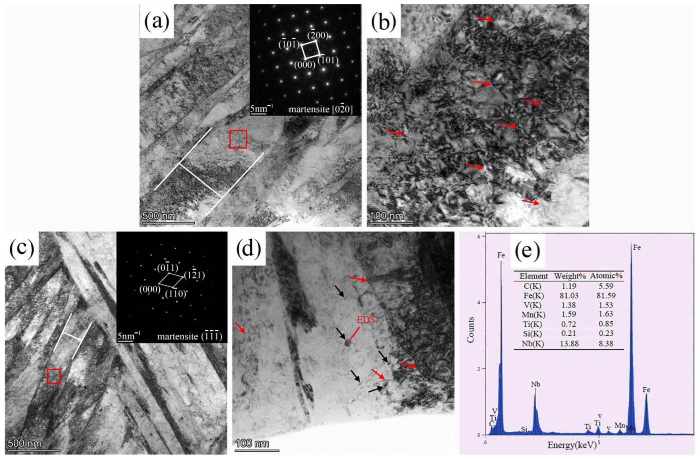
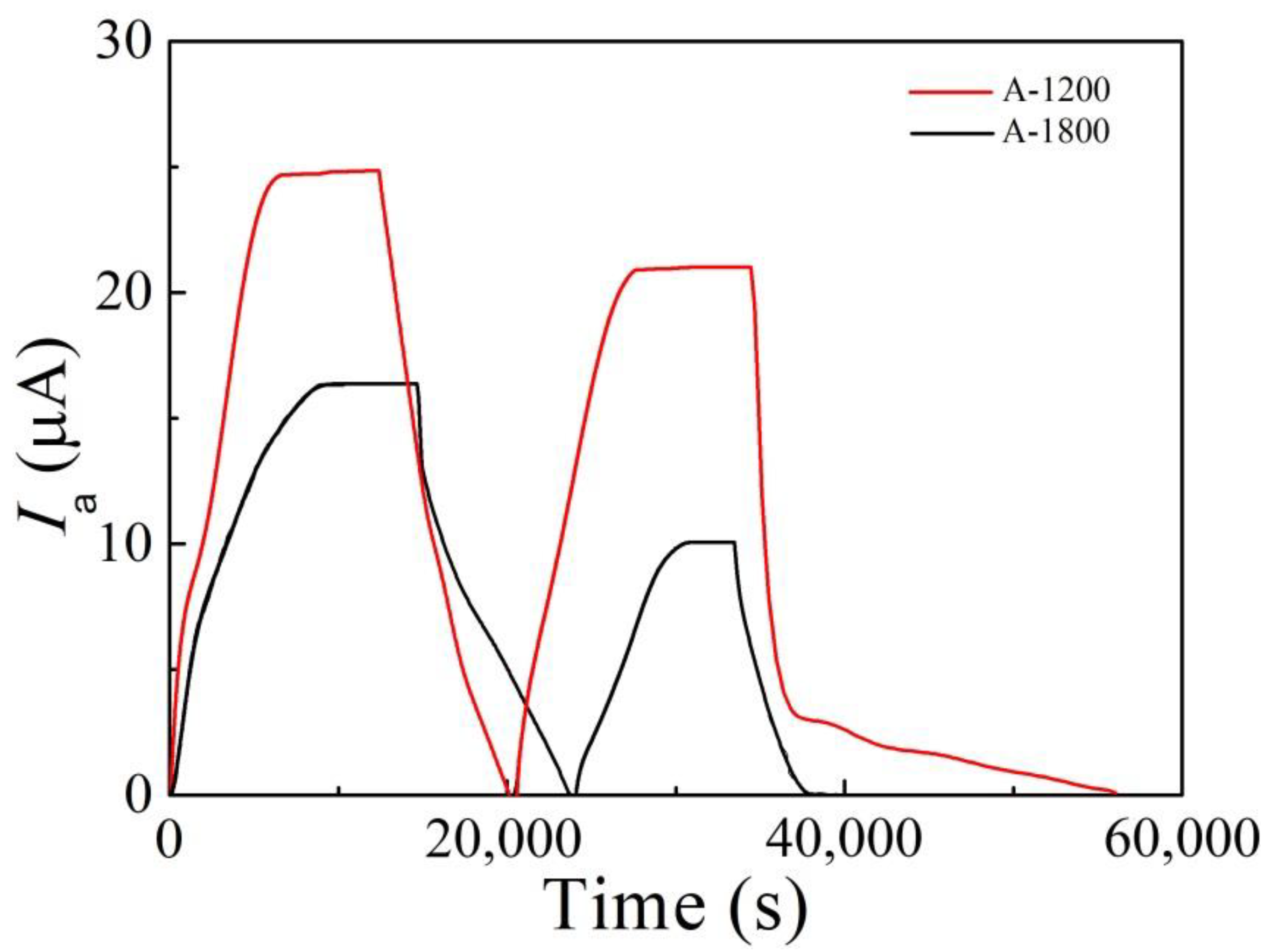
Compared with A-1200 steel, A-1800 steel had a lower hydrogen diffusion coefficient Deff (4.15 × 10⁻⁷ cm2/s) and a higher hydrogen trap density Nt (1.59 × 1021 cm−3). This was ascribed to its fine microstructure and the introduction of a large number of nano-sized carbides.
(2)
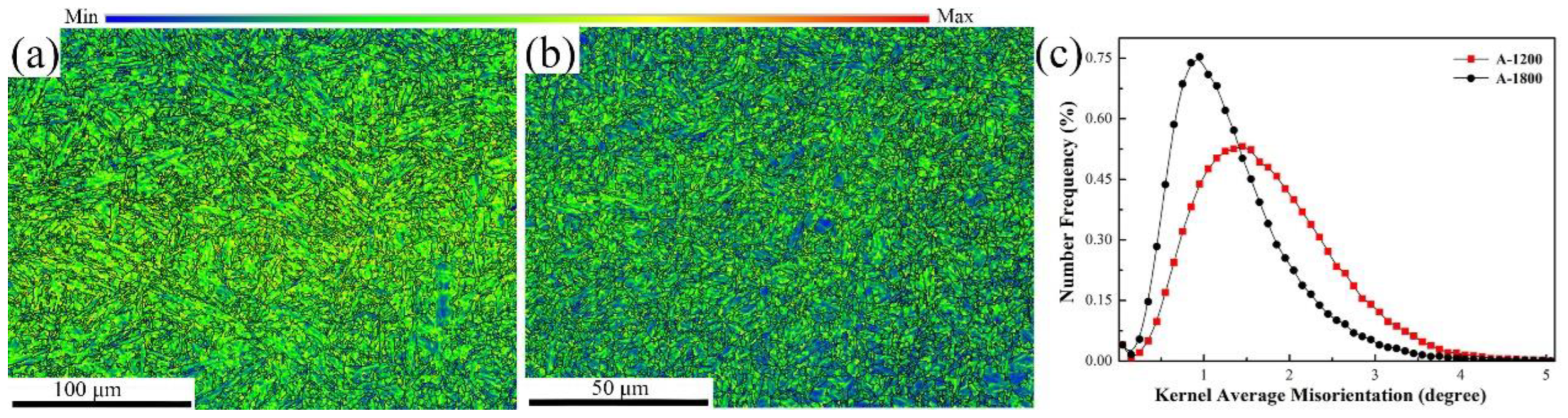
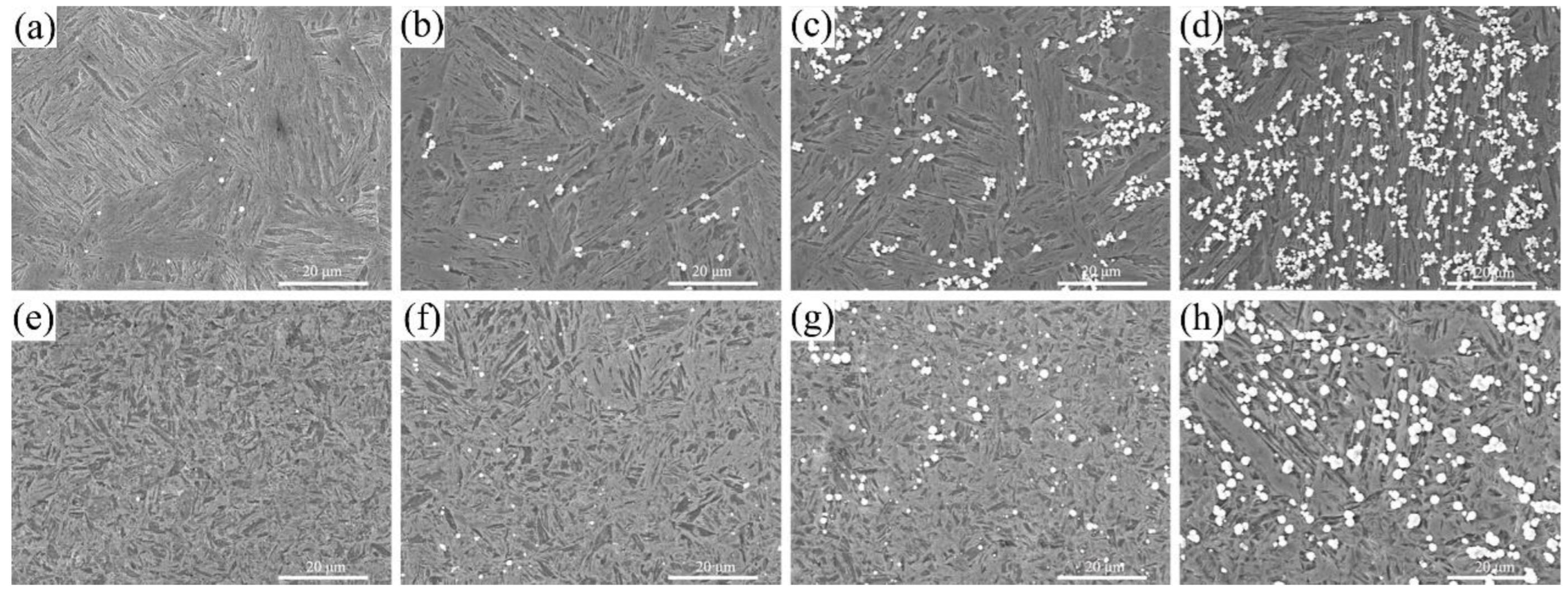
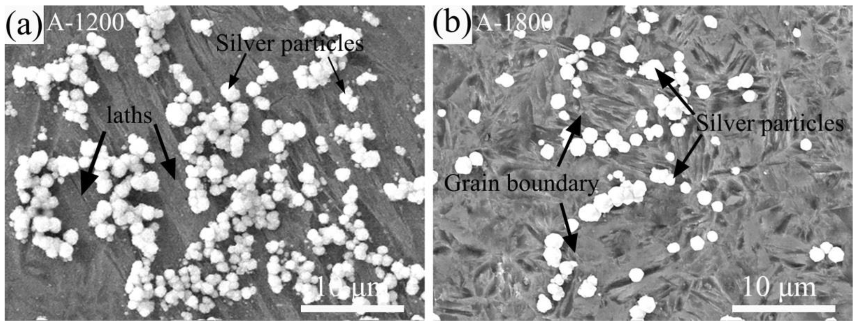
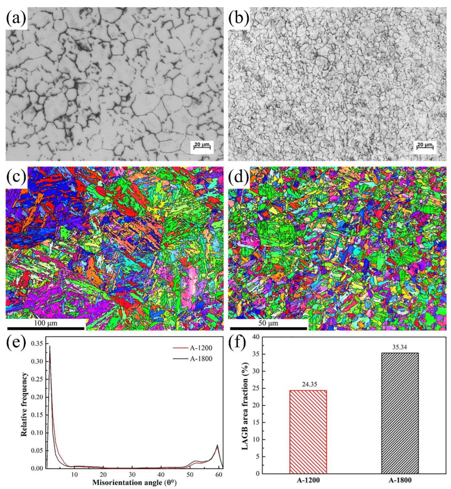
Both steels exhibited the initial hydrogen segregation in the grain boundary. However, the preferential locations of hydrogen accumulation were determined to be lath and grain boundaries for A-1200 and A-1800 steels, respectively. Moreover, markedly improved hydrogen aggregation also was found in A-1800 steel, owing to its fine microstructure and high LAGB area fraction.
(3)
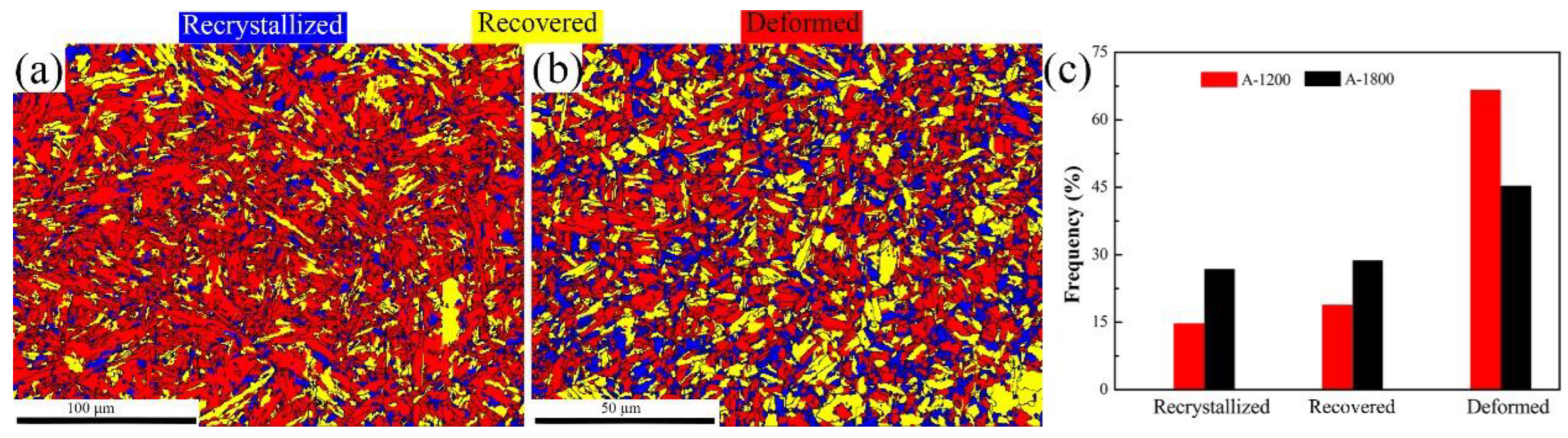
Hydrogen-induced cracking was mainly initiated at lath and grain boundaries for the A-1200 and A-1800 samples, respectively, charged at a current density of 50 mA/cm2 for 24 h. The greatly alleviated hydrogen damage of A-1800 steel was attributed to the low internal stress, high recrystallization fraction, and abundance of nano-sized carbides to weaken the process of HELP.

Author Contributions

T.S., P.W., H.G., Q.D. and H.S. conceived and designed the experiments; P.W. and Q.D. performed the experiments; T.S. and P.W. analyzed the data; and P.W. wrote the paper. All authors have read and agreed to the published version of the manuscript.

Funding

Scientific Research Foundation of Education Department of Anhui Province of China (No. KJ2020ZD26), Key S&T Special Project of Anhui Province (No. 202103a05020036).

Data Availability Statement

Not applicable.

Conflicts of Interest

The authors declare no conflict of interest.

References

  1. Krbasian, H.; Tekkaya, A.E. A review on hot stamping. J. Mater. Process. Technol. 2010, 210, 2103–2118. [Google Scholar] [CrossRef]
  2. Taylor, T.; Clough, A. Critical review of automotive hot-stamped sheet steel from an industrial perspective. J. Mater. Sci. Technol. 2018, 34, 809–861. [Google Scholar] [CrossRef]
  3. Okayasu, M.; Fujiwara, T. Hydrogen embrittlement characteristics of hot-stamped 22MnB5 steel. Int. J. Hydrog. Energy 2021, 46, 19657–19669. [Google Scholar] [CrossRef]
  4. Zheng, Q.; Noorderhaven, N.; Du, J. Making the unlikely marriage work: The integration process of Chinese strategic asset-seeking acquisitions. J. World Bus. 2022, 57, 101305. [Google Scholar] [CrossRef]
  5. Jo, M.C.; Yoo, J.; Kim, S.; Kim, S.; Oh, J.; Bian, J.; Sohn, S.S.; Lee, S. Effects of Nb and Mo alloying on resistance to hydrogen embrittlement in 1.9 GPa-grade hot-stamping steels. Mater. Sci. Eng. A 2020, 789, 139656. [Google Scholar] [CrossRef]
  6. Garet, M.; Brass, A.M.; Haut, C.; Guttierez-Solana, F. Hydrogen trapping on non-metallic inclusions in Cr-Mo low alloy steels. Corros. Sci. 1998, 40, 1073–1086. [Google Scholar] [CrossRef]
  7. Szost, B.A.; Vegter, R.H.; Rivera-Díaz-Del-Castillo, P. Developing bearing steels combining hydrogen resistance and improved hardness. Mater. Des. 2013, 43, 499–506. [Google Scholar] [CrossRef]
  8. Michler, T.; Balogh, M.P. Hydrogen environment embrittlement of an ODS RAF steel—Role of irreversible hydrogen trap sites. Int. J. Hydrog. Energy 2010, 35, 9746–9754. [Google Scholar] [CrossRef]
  9. Huang, W.; Gu, H.; Liu, Q.; Si, T. Suppression of hydrogen-induced damage in 22MnB5 hot stamping steel by micro-alloying. Mater. Chem. Phys. 2020, 256, 123729. [Google Scholar] [CrossRef]
  10. Depover, T.; Verbeken, K. Evaluation of the effect of V4C3 precipitates on the hydrogen induced mechanical degradation in Fe-CV alloys. Mater. Sci. Eng. A 2016, 675, 299–313. [Google Scholar] [CrossRef]
  11. Zhang, S.; Wan, J.; Zhao, Q.; Liu, J.; Huang, F.; Huang, Y.; Li, X. Dual role of nanosized NbC precipitates in hydrogen embrittlement susceptibility of lath martensitic steel. Corros. Sci. 2020, 164, 108345. [Google Scholar] [CrossRef]
  12. Lin, L.; Li, B.; Zhu, G.; Kang, Y.-L.; Liu, R.-D. Effect of niobium precipitation behavior on microstructure and hydrogen induced cracking of press hardening steel 22MnB5. Mater. Sci. Eng. A 2018, 721, 38–46. [Google Scholar] [CrossRef]
  13. Turk, A.; San Martín, D.; Rivera-Díaz-Del-Castillo, P.E.; Galindo-Nava, E.I. Correlation between vanadium carbide size and hydrogen trapping in ferritic steel. Scr. Mater. 2018, 152, 112–116. [Google Scholar] [CrossRef]
  14. Thomas, A.; Szpunar, J.A. Hydrogen diffusion and trapping in X70 pipeline steel. Int. J. Hydrog. Energy 2020, 45, 2390–2404. [Google Scholar] [CrossRef]
  15. Chen, S.S.; Wu, T.I.; Wu., J.K. Effects of deformation on hydrogen degradation in a duplex stainless steel. J. Mater. Sci. 2004, 39, 67–71. [Google Scholar] [CrossRef]
  16. Ichitani, K.; Kanno, M. Visualization of hydrogen diffusion in steels by high sensitivity hydrogen microprint technique. Sci. Technol. Adv. Mater. 2003, 4, 545–551. [Google Scholar] [CrossRef]
  17. Okayasu, M.; Yang, L. Influence of microstructure on the mechanical properties and hydrogen embrittlement characteristics of 1800 MPa grade hot-stamped 22MnB5 steel. J. Mater. Sci. 2019, 54, 5061–5073. [Google Scholar] [CrossRef]
  18. Park, J.; Seong, H.G.; Kim, S.J. Effect of heat treatment conditions on corrosion and hydrogen diffusion behaviors of ultra-strong steel used for automotive applications. Corros. Sci. Technol. 2019, 18, 267–276. [Google Scholar]
  19. Williams, M.M.R. The Mathematics of Diffusion; Crank, J., Ed.; Clarendon Press: Oxford, UK, 1975; 414p. [Google Scholar]
  20. Yen, S.K.; Huang, I.B. Critical hydrogen concentration for hydrogen-induced blistering on AISI 430 stainless steel. Mater. Chem. Phys. 2003, 80, 662–666. [Google Scholar] [CrossRef]
  21. Devanathan, M.A.V.; Stachurski, Z. The mechanism of hydrogen evolution on iron in acid solutions by determination of permeation rates. J. Electrochem. Soc. 1964, 111, 619–623. [Google Scholar] [CrossRef]
  22. Xue, H.B.; Cheng, Y.F. Characterization of inclusions of X80 pipeline steel and its correlation with hydrogen-induced cracking. Corros. Sci. 2011, 53, 1201–1208. [Google Scholar] [CrossRef]
  23. Ovejero-García, J. Hydrogen microprint technique in the study of hydrogen in steels. J. Mater. Sci. 1985, 20, 2623–2629. [Google Scholar] [CrossRef]
  24. Ichitani, K.; Kuramoto, S.; Kanno, M. Quantitative evaluation of detection efficiency of thehydrogen microprint technique applied to steel. Corros. Sci. 2003, 45, 1227–1241. [Google Scholar] [CrossRef]
  25. Mohtadi-Bonab, M.A.; Szpunar, J.A.; Collins, L.; Stankievech, R. Evaluation of hydrogen induced cracking behavior of API X70 pipeline steel at different heat treatments. Int. J. Hydrog. Energy 2014, 39, 6076–6088. [Google Scholar] [CrossRef]
  26. Si, T.; Liu, Y.; Zhang, Q.; Liu, D.; Li, Y. Effect of Microstructure on Hydrogen Permeation in EA4T and 30CrNiMoV12 Railway Axle Steels. Metals 2019, 9, 164. [Google Scholar] [CrossRef] [Green Version]
  27. Wang, Y.; Xiong, L.; Liu, S. Rapid Hydrogen Transportation Along Grain Boundary in Nickel. Acta. Metall. Sin. 2014, 27, 615–620. [Google Scholar] [CrossRef]
  28. Tian, H.; Li, Y.; Wang, X.; Cui, Z. Combined effect of cathodic potential and sulfur species on calcareous deposition, hydrogen permeation and hydrogen embrittlement of a low carbon bainite steel in artificial seawater. Corros. Sci. 2019, 158, 108089. [Google Scholar] [CrossRef]
  29. Harris, T.M.; Latanision, M. Grain boundary diffusion of hydrogen in nickel. Metall. Trans. A 1991, 22, 351–355. [Google Scholar] [CrossRef]
  30. Brass, A.M.; Chanfreau, A. Accelerated diffusion of hydrogen along grain boundaries in nickel. Acta Mater. 1996, 44, 3823–3831. [Google Scholar] [CrossRef]
  31. Li, L.; Song, B.; Cai, Z.; Liu, Z.; Cui, X. Effect of vanadium content on hydrogen diffusion behaviors and hydrogen induced ductility loss of X80 pipeline steel. Mater. Sci. Eng. A 2019, 742, 712–721. [Google Scholar] [CrossRef]
  32. Du, Y.A.; Ismer, L.; Rogal, J.; Hickel, T.; Neugebauer, J.; Drautz, R. First-principles study on the interaction of H interstitials with grain boundaries in α-and γ-Fe. Phys. Rev. B 2011, 84, 144121. [Google Scholar] [CrossRef]
  33. Hojo, T.; Akiyama, E.; Saitoh, H.; Shiro, A.; Yasuda, R.; Shobu, T.; Kinugasa, J.; Yuse, F. Effects of residual stress and plastic strain on hydrogen embrittlement of a stretch-formed TRIP-aided martensitic steel sheet. Corros. Sci. 2020, 177, 108957. [Google Scholar] [CrossRef]
  34. Zhang, S.; Xu, D.; Huang, F.; Gao, W.; Wan, J.; Liu, J. Mitigation of hydrogen embrittlement in ultra-high strength lath martensitic steel via Ta microalloying. Mater. Des. 2021, 210, 110090. [Google Scholar] [CrossRef]
Figure 1. Devanathan–Stachurski cell for hydrogen permeation.
Metals 12 01075 g001
Figure 2. Schematic diagram of HMT.
Metals 12 01075 g002
Figure 3. Hydrogen permeation curves of A-1200 and A-1800 steels.
Metals 12 01075 g003
Figure 4. TEM images showing (a) lath martensite and (b) dislocation tangle in A-1200 steel, as well as (c) lath martensite and (d) precipitates in A-1800 steel and (e) the corresponding EDX results of the carbide marked by red arrows in d. The inset maps in a,b show the SAD patterns of the corresponding red box regions.
Metals 12 01075 g004
Figure 5. SEM micrographs of HMT test specimens charged for 20, 60, 90, and 120 min: (ad) A-1200 and (eh) A-1800.
Metals 12 01075 g005
Figure 6. Locations of hydrogen accumulation in samples charged for 120 min: (a) A-1200 and (b) A-1800.
Metals 12 01075 g006
Figure 7. Grain sizes and EBSD maps of (a,c) A-1200 steel and (b,d) A-1800 steel, as well as their (e) misorientation distributions and (f) LAGB area fractions.
Metals 12 01075 g007
Figure 8. SEM images of crack distribution: (a) A-1200 and (b) A-1800 samples.
Metals 12 01075 g008
Figure 9. KAM maps of (a) A-1200 steel and (b) A-1800 steel, as well as (c) their KAM fractions.
Metals 12 01075 g009
Figure 10. EBSD recrystallization maps of (a) A-1200 and (b) A-1800 steels, as well as (c) volume fractions of recrystallized, recovered, and deformed regions.
Metals 12 01075 g010
Table 1. Chemical compositions of hot-stamped steels (wt.%).
SampleCSiMnPSCrBTiNbVFe
A-12000.230.291.270.010.0060.180.0035---Bal.
A-18000.320.251.000.010.0030.200.00370.0300.0350.035Bal.
Table 2. Hydrogen permeation parameters of A-1200 and A-1800 steels.
ParametersA-1200 SteelA-1800 Steel
1st Charging2nd Charging1st Charging2nd Charging
L (mm)1.031.031.051.05
T0.63 (s)3305301044304010
I (μA)23.8620.0117.3712.08
JL (mol m−1 s−1)1.44 × 10−111.21 × 10−111.07 × 10−110.74 × 10⁻¹¹
Deff (cm2 s−1)5.35 × 10−75.43 × 10−74.15 × 10−74.58 × 10−7
Capp (wppm)3.54 ± 0.022.92 ± 0.013.39 ± 0.042.13 ± 0.02
Nt (cm−3)1.29 × 10211.05 × 10211.59 × 10210.91 × 1021
Nr (cm−3)1.05 × 10²¹ 0.91 × 10²¹
Nir (cm−3)0.24 × 10²¹ 0.68 × 10²¹
Table 3. Features of cracks for the hydrogen-charged samples.
SampleNumber of CracksAverage Length (μm)Average Width (μm)Initiation Site (number)Propagation
Method
A-12001112.251.37Lath (8)Transgranular
A-180033.710.74Grain boundary (2)Intergranular
Publisher’s Note: MDPI stays neutral with regard to jurisdictional claims in published maps and institutional affiliations.

