
In-Situ Alloying of CoCrFeNiX High Entropy Alloys by Selective Laser Melting


Abstract
:1. Introduction
2. Materials and Methods
3. Results
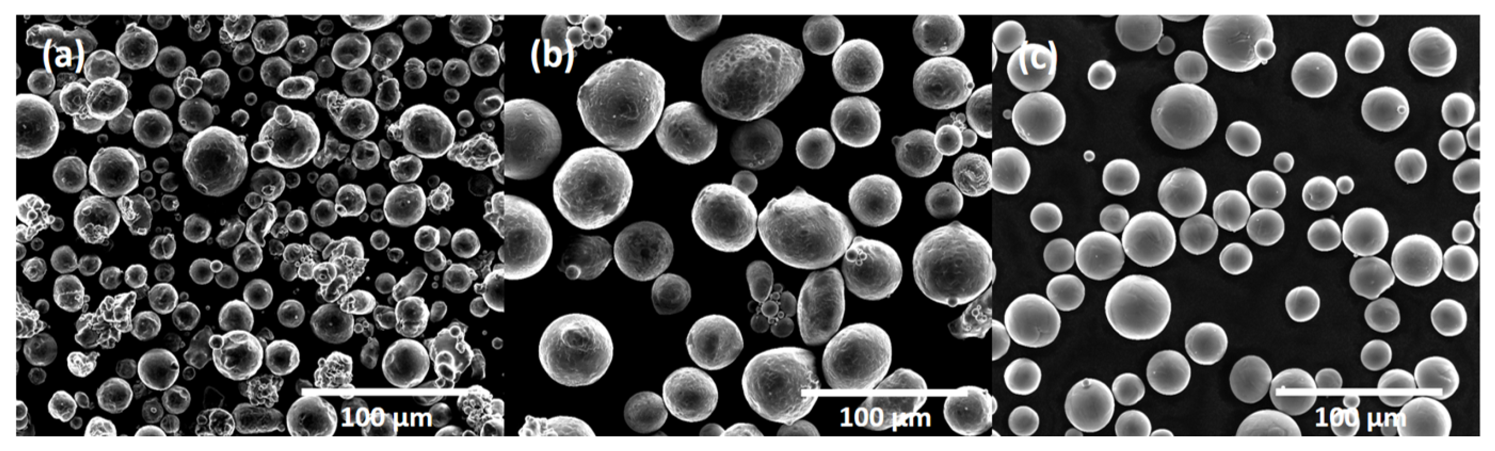
3.1. Powder Analysis
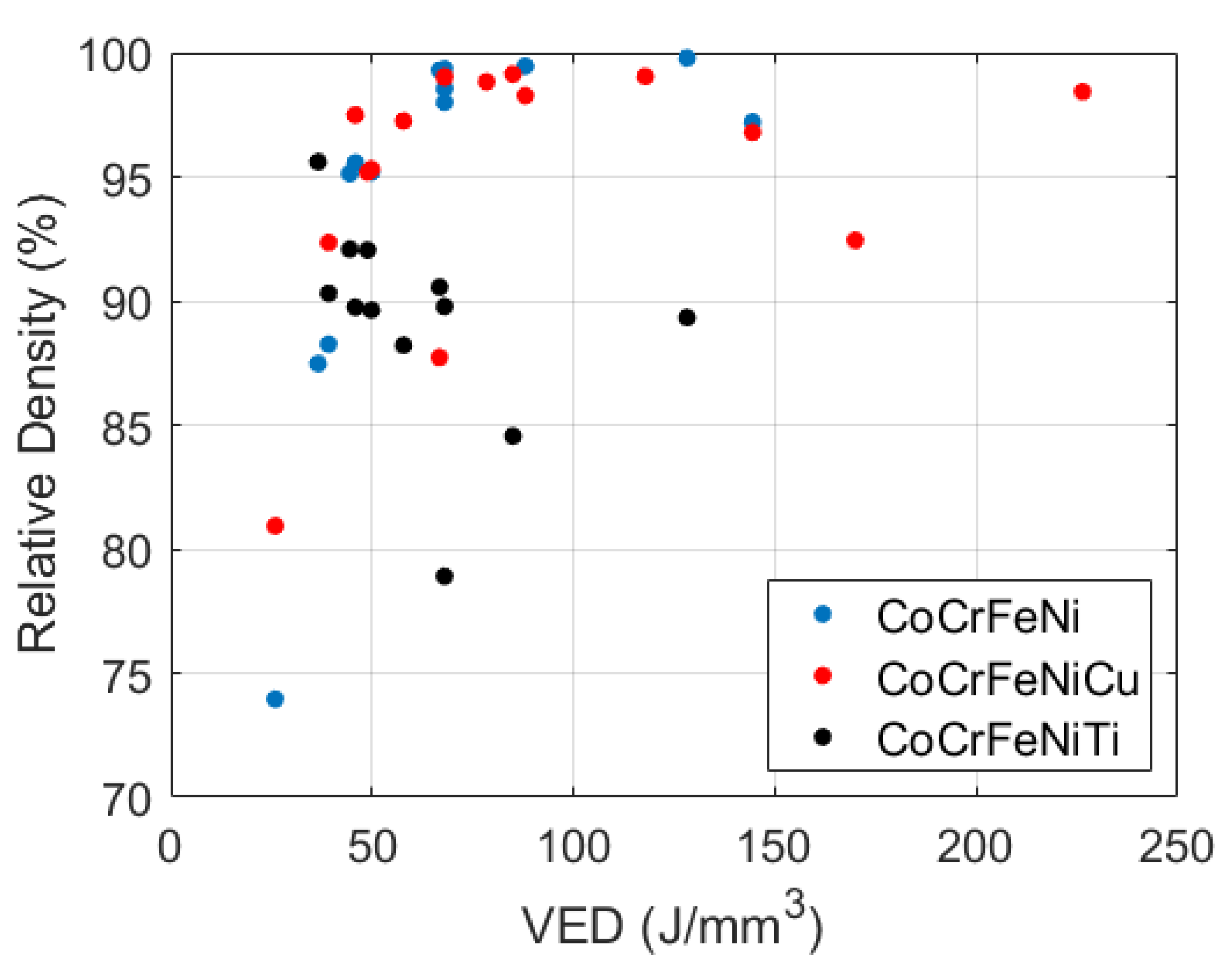
3.2. Processing Parameters and Density
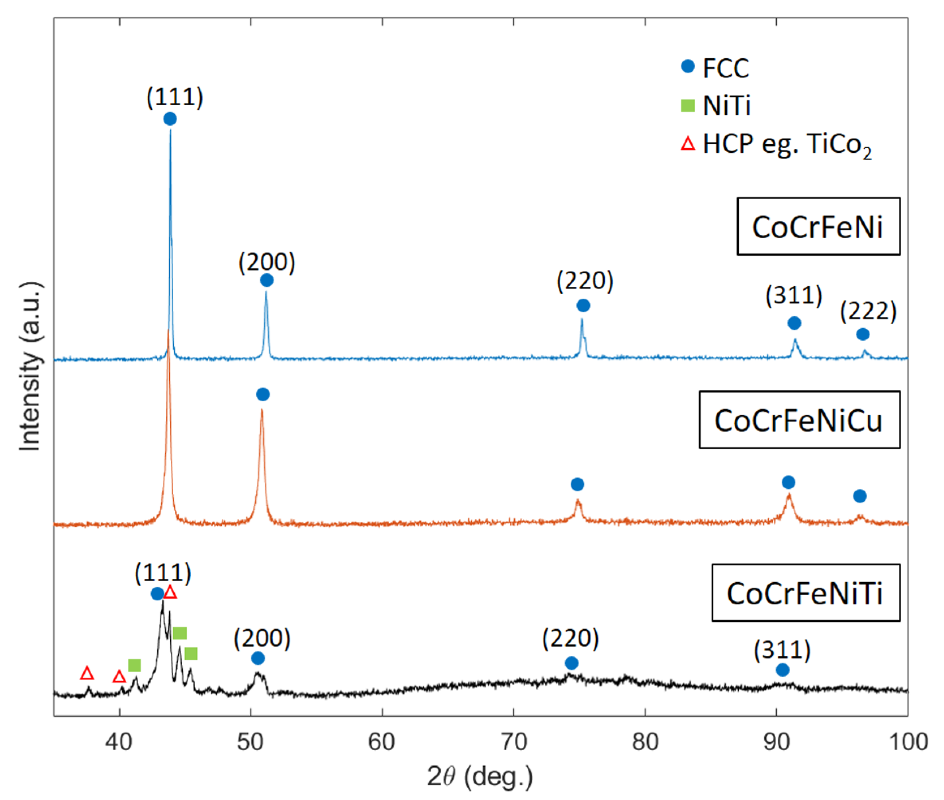
3.3. XRD
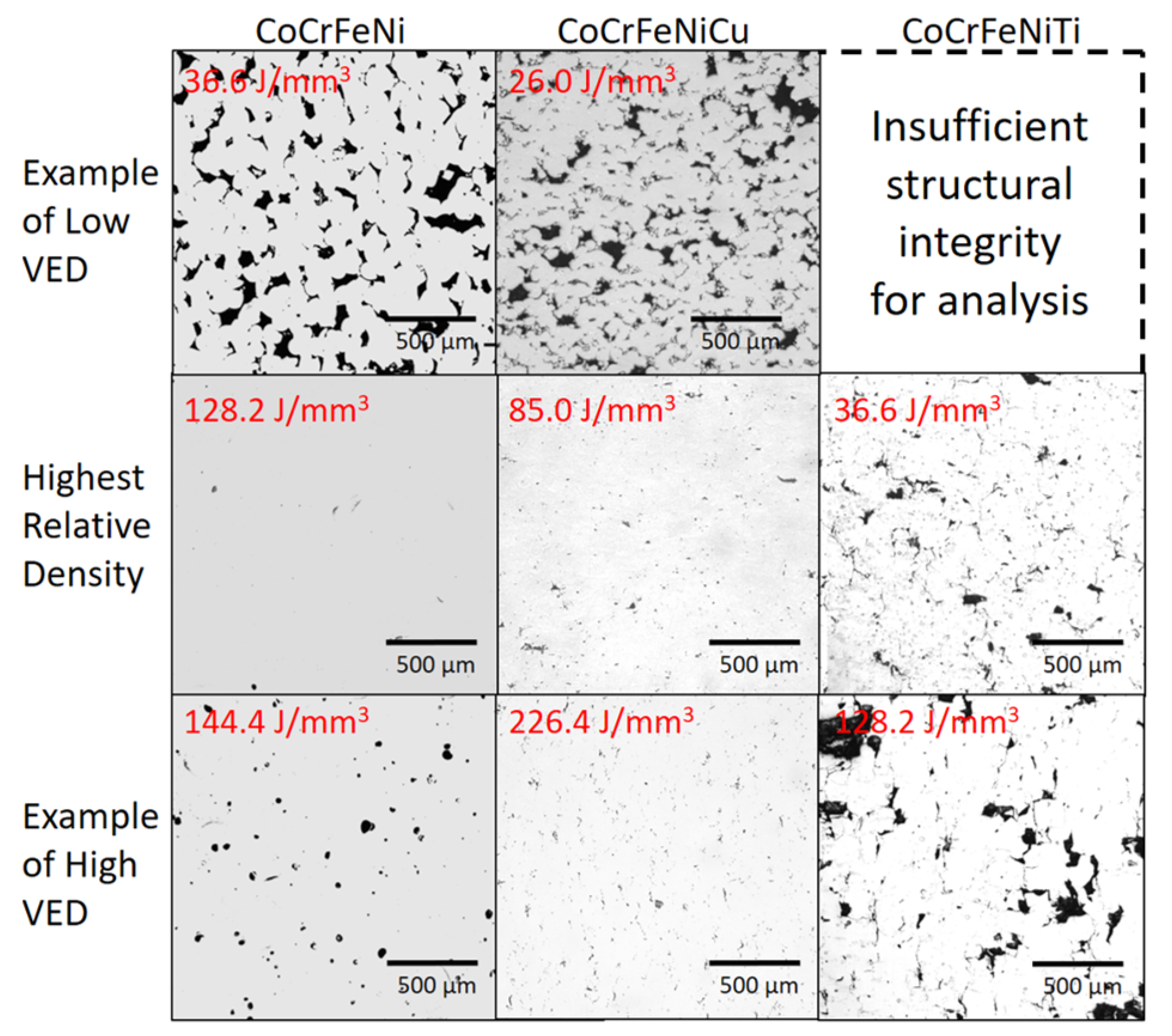
3.4. Microstructure
4. Discussion
5. Conclusions
- The build of the CoCrFeNi alloy resulted in a sample with high relative density at a VED of 128.2 J/mm and single phase FCC microstructure with a clear and wide processing window.
- The build of the CoCrFeNiCu alloy showed high relative density, a well-defined processing window and two FCC phases; one depleted and one rich in Cu. The VED which produced the highest relative density was low at 85.0 J/mm compared to that of the CoCrFeNi, most likely due to the addition of Cu which has a lower melting point. The Cu did alloy with the pre-alloyed base powder but there were large areas of high Cu concentration due to its inherent tendency to segregate with the other constituent elements.
- The build of CoCrFeNiTi show a low relative density and no clear processing window. Some Ti particles remained un-melted, while some Ti had alloyed to produce brittle intermetallic NiTi and HCP phases in an FCC matrix. There was extensive solid-state residual stress cracking seen in every sample. The VED which resulted in the sample of highest density was low at 36.6 J/mm, as this was the sample in which the least cracking occurred even though there was some lack of fusion porosity.
- A component of the success of in-situ alloying is deemed dependent on the melting temperature of the elemental powder being less than or comparable to the melting temperature of the base alloy powder. In this case the melting temperature of Cu (1084 C) is much lower than that of CoCrFeNi (1414 C) and the melting point of Ti is higher (1688 C), resulting in un-melted Ti particles.
- The tendency of the additional element to segregate at grain boundaries, in the same alloy manufactured by other methods, should also be an indicator of whether that elemental addition is suitable for in-situ alloying. If the element tends to segregate, like Cu in this study, this can result in areas of high concentration of that element, with a differing morphology to common grain boundary segregation.
Author Contributions
Funding
Institutional Review Board Statement
Informed Consent Statement
Data Availability Statement
Conflicts of Interest
References
- Yeh, J.W.; Chen, S.K.; Lin, S.J.; Gan, J.Y.; Chin, T.S.; Shun, T.T.; Tsau, C.H.; Chang, S.Y. Nanostructured high-entropy alloys with multiple principal elements: Novel alloy design concepts and outcomes. Adv. Eng. Mater. 2004, 6, 299–303. [Google Scholar] [CrossRef]
- Brif, Y.; Thomas, M.; Todd, I. The use of high-entropy alloys in additive manufacturing. Scr. Mater. 2015, 99, 93–96. [Google Scholar] [CrossRef]
- Wu, Z.; Bei, H.; Otto, F.; Pharr, G.M.; George, E.P. Recovery, recrystallization, grain growth and phase stability of a family of FCC-structured multi-component equiatomic solid solution alloys. Intermetallics 2014, 46, 131–140. [Google Scholar] [CrossRef]
- Salishchev, G.A.; Tikhonovsky, M.A.; Shaysultanov, D.G.; Stepanov, N.D.; Kuznetsov, A.V.; Kolodiy, I.V.; Tortika, A.S.; Senkov, O.N. Effect of Mn and v on structure and mechanical properties of high-entropy alloys based on CoCrFeNi system. J. Alloys Compd. 2014, 591, 11–21. [Google Scholar] [CrossRef]
- Cantor, B.; Chang, I.T.; Knight, P.; Vincent, A.J. Microstructural development in equiatomic multicomponent alloys. Mater. Sci. Eng. A 2004, 375–377, 213–218. [Google Scholar] [CrossRef]
- Ostovari Moghaddam, A.; Shaburova, N.A.; Samodurova, M.N.; Abdollahzadeh, A.; Trofimov, E.A. Additive manufacturing of high entropy alloys: A practical review. J. Mater. Sci. Technol. 2021, 77, 131–162. [Google Scholar] [CrossRef]
- Torralba, J.M.; Campos, M. High entropy alloys manufactured by additive manufacturing. Metals 2020, 10, 639. [Google Scholar] [CrossRef]
- Zhang, H.; Pan, Y.; He, Y.Z. Synthesis and characterization of FeCoNiCrCu high-entropy alloy coating by laser cladding. Mater. Des. 2011, 32, 1910–1915. [Google Scholar] [CrossRef]
- Yao, J.; Weng, Z.; Dong, G.; Yang, L. Microstructure and hardness of FeCrNiCoMn high-entropy alloy coating prepared by laser cladding with pre-alloyed gas atomized powder. In Proceedings of the ICALEO 2013—32nd International Congress on Applications of Lasers and Electro-Optics, Miami, FL, USA, 8–10 October 2013; Volume 480, pp. 480–486. [Google Scholar] [CrossRef]
- Zhang, C.; Chen, G.J.; Dai, P.Q. Evolution of the microstructure and properties of laser-clad FeCrNiCoBx high-entropy alloy coatings. Mater. Sci. Technol. 2016, 32, 1666–1672. [Google Scholar] [CrossRef]
- Muangtong, P.; Rodchanarowan, A.; Chaysuwan, D.; Chanlek, N.; Goodall, R. The corrosion behaviour of CoCrFeNi-x (x = Cu, Al, Sn) high entropy alloy systems in chloride solution. Corros. Sci. 2020, 172, 108740. [Google Scholar] [CrossRef]
- Qiu, Z.; Yao, C.; Feng, K.; Li, Z.; Chu, P.K. Cryogenic deformation mechanism of CrMnFeCoNi high-entropy alloy fabricated by laser additive manufacturing process. Int. J. Lightweight Mater. Manuf. 2018, 1, 33–39. [Google Scholar] [CrossRef]
- Xiang, S.; Luan, H.; Wu, J.; Yao, K.F.; Li, J.; Liu, X.; Tian, Y.; Mao, W.; Bai, H.; Le, G.; et al. Microstructures and mechanical properties of CrMnFeCoNi high entropy alloys fabricated using laser metal deposition technique. J. Alloys Compd. 2019, 773, 387–392. [Google Scholar] [CrossRef]
- Xiang, S.; Li, J.; Luan, H.; Amar, A.; Lu, S.; Li, K.; Zhang, L.; Liu, X.; Le, G.; Wang, X.; et al. Effects of process parameters on microstructures and tensile properties of laser melting deposited CrMnFeCoNi high entropy alloys. Mater. Sci. Eng. A 2019, 743, 412–417. [Google Scholar] [CrossRef]
- Chen, P.; Li, S.; Zhou, Y.; Yan, M.; Attallah, M.M. Fabricating CoCrFeMnNi high entropy alloy via selective laser melting in-situ alloying. J. Mater. Sci. Technol. 2020, 43, 40–43. [Google Scholar] [CrossRef]
- Cagirici, M.; Wang, P.; Ng, F.L.; Nai, M.L.S.; Ding, J.; Wei, J. Additive manufacturing of high-entropy alloys by thermophysical calculations and in situ alloying. J. Mater. Sci. Technol. 2021, 94, 53–66. [Google Scholar] [CrossRef]
- Zhang, H.; Zhao, Y.; Huang, S.; Zhu, S.; Wang, F.; Li, D. Manufacturing and analysis of high-performance refractory high-entropy alloy via selective laser melting (SLM). Materials 2019, 12, 720. [Google Scholar] [CrossRef] [Green Version]
- Zhang, H.; Xu, W.; Xu, Y.; Lu, Z.; Li, D. The thermal-mechanical behavior of WTaMoNb high-entropy alloy via selective laser melting (SLM): Experiment and simulation. Int. J. Adv. Manuf. Technol. 2018, 96, 461–474. [Google Scholar] [CrossRef]
- Melia, M.A.; Whetten, S.R.; Puckett, R.; Jones, M.; Heiden, M.J.; Argibay, N.; Kustas, A.B. High-throughput additive manufacturing and characterization of refractory high entropy alloys. Appl. Mater. Today 2020, 19, 100560. [Google Scholar] [CrossRef]
- Moorehead, M.; Bertsch, K.; Niezgoda, M.; Parkin, C.; Elbakhshwan, M.; Sridharan, K.; Zhang, C.; Thoma, D.; Couet, A. High-throughput synthesis of Mo-Nb-Ta-W high-entropy alloys via additive manufacturing. Mater. Des. 2020, 187, 108358. [Google Scholar] [CrossRef]
- Wu, Y.; Liaw, P.K.; Zhang, Y. Preparation of bulk tizrnbmov and nbtialtav high-entropy alloys by powder sintering. Metals 2021, 11, 1748. [Google Scholar] [CrossRef]
- Kuzminova, Y.; Firsov, D.; Dudin, A.; Sergeev, S.; Zhilyaev, A.; Dyakov, A.; Chupeeva, A.; Alekseev, A.; Martynov, D.; Akhatov, I.; et al. The effect of the parameters of the powder bed fusion process on the microstructure and mechanical properties of CrFeCoNi medium-entropy alloys. Intermetallics 2020, 116, 106651. [Google Scholar] [CrossRef]
- Zhu, Z.G.; Nguyen, Q.B.; Ng, F.L.; An, X.H.; Liao, X.Z.; Liaw, P.K.; Nai, S.M.; Wei, J. Hierarchical microstructure and strengthening mechanisms of a CoCrFeNiMn high entropy alloy additively manufactured by selective laser melting. Scr. Mater. 2018, 154, 20–24. [Google Scholar] [CrossRef]
- Sun, Z.; Tan, X.; Wang, C.; Descoins, M.; Mangelinck, D.; Tor, S.B.; Jägle, E.A.; Zaefferer, S.; Raabe, D. Reducing hot tearing by grain boundary segregation engineering in additive manufacturing: Example of an AlxCoCrFeNi high-entropy alloy. Acta Mater. 2021, 204, 116505. [Google Scholar] [CrossRef]
- Wang, P.; Huang, P.; Ng, F.L.; Sin, W.J.; Lu, S.; Nai, M.L.S.; Dong, Z.L.; Wei, J. Additively manufactured CoCrFeNiMn high-entropy alloy via pre-alloyed powder. Mater. Des. 2019, 168, 107576. [Google Scholar] [CrossRef]
- Li, R.; Niu, P.; Yuan, T.; Cao, P.; Chen, C.; Zhou, K. Selective laser melting of an equiatomic CoCrFeMnNi high-entropy alloy: Processability, non-equilibrium microstructure and mechanical property. J. Alloys Compd. 2018, 746, 125–134. [Google Scholar] [CrossRef]
- Kim, Y.K.; Choe, J.; Lee, K.A. Selective laser melted equiatomic CoCrFeMnNi high-entropy alloy: Microstructure, anisotropic mechanical response, and multiple strengthening mechanism. J. Alloys Compd. 2019, 805, 680–691. [Google Scholar] [CrossRef]
- Niu, P.; Li, R.; Zhu, S.; Wang, M.; Chen, C.; Yuan, T. Hot cracking, crystal orientation and compressive strength of an equimolar CoCrFeMnNi high-entropy alloy printed by selective laser melting. Opt. Laser Technol. 2020, 127, 106147. [Google Scholar] [CrossRef]
- Xu, Z.; Zhang, H.; Li, W.; Mao, A.; Wang, L.; Song, G.; He, Y. Microstructure and nanoindentation creep behavior of CoCrFeMnNi high-entropy alloy fabricated by selective laser melting. Addit. Manuf. 2019, 28, 766–771. [Google Scholar] [CrossRef]
- Niu, P.D.; Li, R.D.; Yuan, T.C.; Zhu, S.Y.; Chen, C.; Wang, M.B.; Huang, L. Microstructures and properties of an equimolar AlCoCrFeNi high entropy alloy printed by selective laser melting. Intermetallics 2019, 104, 24–32. [Google Scholar] [CrossRef]
- Karlsson, D.; Marshal, A.; Johansson, F.; Schuisky, M.; Sahlberg, M.; Schneider, J.M.; Jansson, U. Elemental segregation in an AlCoCrFeNi high-entropy alloy—A comparison between selective laser melting and induction melting. J. Alloys Compd. 2019, 784, 195–203. [Google Scholar] [CrossRef]
- Zhou, P.F.; Xiao, D.H.; Wu, Z.; Ou, X.Q. Al0.5FeCoCrNi high entropy alloy prepared by selective laser melting with gas-atomized pre-alloy powders. Mater. Sci. Eng. A 2019, 739, 86–89. [Google Scholar] [CrossRef]
- Ocelík, V.; Janssen, N.; Smith, S.N.; De Hosson, J.T.M. Additive Manufacturing of High-Entropy Alloys by Laser Processing. JOM 2016, 68, 1810–1818. [Google Scholar] [CrossRef] [Green Version]
- Luo, S.; Gao, P.; Yu, H.; Yang, J.; Wang, Z.; Zeng, X. Selective laser melting of an equiatomic AlCrCuFeNi high-entropy alloy: Processability, non-equilibrium microstructure and mechanical behavior. J. Alloys Compd. 2019, 771, 387–397. [Google Scholar] [CrossRef]
- Wang, Y.; Li, R.; Niu, P.; Zhang, Z.; Yuan, T.; Yuan, J.; Li, K. Microstructures and properties of equimolar AlCoCrCuFeNi high-entropy alloy additively manufactured by selective laser melting. Intermetallics 2020, 120, 106746. [Google Scholar] [CrossRef]
- Zhang, M.; Zhou, X.; Wang, D.; Zhu, W.; Li, J.; Zhao, Y.F. AlCoCuFeNi high-entropy alloy with tailored microstructure and outstanding compressive properties fabricated via selective laser melting with heat treatment. Mater. Sci. Eng. A 2019, 743, 773–784. [Google Scholar] [CrossRef]
- Fujieda, T.; Shiratori, H.; Kuwabara, K.; Kato, T.; Yamanaka, K.; Koizumi, Y.; Chiba, A. First demonstration of promising selective electron beam melting method for utilizing high-entropy alloys as engineering materials. Mater. Lett. 2015, 159, 12–15. [Google Scholar] [CrossRef]
- Fujieda, T.; Shiratori, H.; Kuwabara, K.; Hirota, M.; Kato, T.; Yamanaka, K.; Koizumi, Y.; Chiba, A.; Watanabe, S. CoCrFeNiTi-based high-entropy alloy with superior tensile strength and corrosion resistance achieved by a combination of additive manufacturing using selective electron beam melting and solution treatment. Mater. Lett. 2017, 189, 148–151. [Google Scholar] [CrossRef]
- Fujieda, T.; Chen, M.; Shiratori, H.; Kuwabara, K.; Yamanaka, K.; Koizumi, Y.; Chiba, A.; Watanabe, S. Mechanical and corrosion properties of CoCrFeNiTi-based high-entropy alloy additive manufactured using selective laser melting. Addit. Manuf. 2019, 25, 412–420. [Google Scholar] [CrossRef]
- Liu, H.; Li, X.; Liu, J.; Gao, W.; Du, X.; Hao, J. Microstructural evolution and properties of dual-layer CoCrFeMnTi0.2 high-entropy alloy coating fabricated by laser cladding. Opt. Laser Technol. 2021, 134, 106646. [Google Scholar] [CrossRef]
- Shun, T.T.; Chang, L.Y.; Shiu, M.H. Microstructures and mechanical properties of multiprincipal component CoCrFeNiTi x alloys. Mater. Sci. Eng. A 2012, 556, 170–174. [Google Scholar] [CrossRef]
- Park, N.; Watanabe, I.; Terada, D.; Yokoyama, Y.; Liaw, P.K.; Tsuji, N. Recrystallization Behavior of CoCrCuFeNi High-Entropy Alloy. Metall. Mater. Trans. Phys. Metall. Mater. Sci. 2015, 46, 1481–1487. [Google Scholar] [CrossRef] [Green Version]
- Chen, R.; Qin, G.; Zheng, H.; Wang, L.; Su, Y.; Chiu, Y.; Ding, H.; Guo, J.; Fu, H. Composition design of high entropy alloys using the valence electron concentration to balance strength and ductility. Acta Mater. 2018, 144, 129–137. [Google Scholar] [CrossRef]
- Tong, C.J.; Chen, Y.L.; Chen, S.K.; Yeh, J.W.; Shun, T.T.; Tsau, C.H.; Lin, S.J.; Chang, S.Y. Microstructure characterization of AlxCoCrCuFeNi high-entropy alloy system with multiprincipal elements. Metall. Mater. Trans. Phys. Metall. Mater. Sci. 2005, 36, 881–893. [Google Scholar] [CrossRef]
- Wu, P.H.; Liu, N.; Zhou, P.J.; Peng, Z.; Du, W.D.; Wang, X.J.; Pan, Y. Microstructures and liquid phase separation in multicomponent CoCrCuFeNi high entropy alloys. Mater. Sci. Technol. 2016, 32, 576–580. [Google Scholar] [CrossRef]
- Rogal, Ł. Semi-solid processing of the CoCrCuFeNi high entropy alloy. Mater. Des. 2017, 119, 406–416. [Google Scholar] [CrossRef]
- Schneider, C.A.; Rasband, W.S.; Eliceiri, K.W. NIH Image to ImageJ: 25 years of image analysis. Nat. Methods 2012, 9, 671–675. [Google Scholar] [CrossRef]
- Farzadfar, S.A.; Murtagh, M.J.; Venugopal, N. Impact of IN718 bimodal powder size distribution on the performance and productivity of laser powder bed fusion additive manufacturing process. Powder Technol. 2020, 375, 60–80. [Google Scholar] [CrossRef]
- Thomas, M.; Baxter, G.J.; Todd, I. Normalised model-based processing diagrams for additive layer manufacture of engineering alloys. Acta Mater. 2016, 108, 26–35. [Google Scholar] [CrossRef] [Green Version]
- Verma, A.; Tarate, P.; Abhyankar, A.C.; Mohape, M.R.; Gowtam, D.S.; Deshmukh, V.P.; Shanmugasundaram, T. High temperature wear in CoCrFeNiCux high entropy alloys: The role of Cu. Scr. Mater. 2019, 161, 28–31. [Google Scholar] [CrossRef]
- Zhang, C.; Feng, K.; Kokawa, H.; Han, B.; Li, Z. Cracking mechanism and mechanical properties of selective laser melted CoCrFeMnNi high entropy alloy using different scanning strategies. Mater. Sci. Eng. A 2020, 789, 139672. [Google Scholar] [CrossRef]


| Element | Fe | Co | Cr | Ni | Al | Si | Zr | Other |
|---|---|---|---|---|---|---|---|---|
| wt.% | 23.48 | 26.28 | 21.07 | 27.16 | 0.14 | 0.10 | 0.11 | <0.05 |
| Powder | D10 (m) | D50 (m) | D90 (m) |
|---|---|---|---|
| CoCrFeNi | 17.9 | 30.1 | 49.0 |
| Cu | 26.5 | 40.0 | 59.8 |
| Ti | 19.9 | 29.2 | 42.8 |
| Alloy | Relative Density (%) | Laser Power P (W) | Scanning Velocity v (mm/s) | Hatch Spacing h (m) | Layer Thickness t (m) | VED (J/mm) |
|---|---|---|---|---|---|---|
| CoCrFeNi | 99.88 | 94 | 582 | 42 | 30 | 128.2 |
| CoCrFeNiCu | 99.13 | 130 | 850 | 60 | 30 | 85.0 |
| CoCrFeNiTi | 95.61 | 70 | 850 | 75 | 30 | 36.6 |
Publisher’s Note: MDPI stays neutral with regard to jurisdictional claims in published maps and institutional affiliations. |
© 2022 by the authors. Licensee MDPI, Basel, Switzerland. This article is an open access article distributed under the terms and conditions of the Creative Commons Attribution (CC BY) license (https://creativecommons.org/licenses/by/4.0/).
Share and Cite
Farquhar, L.; Maddison, G.; Hardwick, L.; Livera, F.; Todd, I.; Goodall, R. In-Situ Alloying of CoCrFeNiX High Entropy Alloys by Selective Laser Melting. Metals 2022, 12, 456. https://doi.org/10.3390/met12030456
Farquhar L, Maddison G, Hardwick L, Livera F, Todd I, Goodall R. In-Situ Alloying of CoCrFeNiX High Entropy Alloys by Selective Laser Melting. Metals. 2022; 12(3):456. https://doi.org/10.3390/met12030456
Chicago/Turabian StyleFarquhar, Lucy, George Maddison, Liam Hardwick, Frances Livera, Iain Todd, and Russell Goodall. 2022. "In-Situ Alloying of CoCrFeNiX High Entropy Alloys by Selective Laser Melting" Metals 12, no. 3: 456. https://doi.org/10.3390/met12030456
APA StyleFarquhar, L., Maddison, G., Hardwick, L., Livera, F., Todd, I., & Goodall, R. (2022). In-Situ Alloying of CoCrFeNiX High Entropy Alloys by Selective Laser Melting. Metals, 12(3), 456. https://doi.org/10.3390/met12030456