Article

Tribocorrosion Behavior of CoCrNi Medium Entropy Alloy in Simulated Seawater

State Key Laboratory of Solidification Processing, Center of Advanced Lubrication and Seal Materials, Northwestern Polytechnical University, Xi’an 710072, China
*
Authors to whom correspondence should be addressed.
Metals 2022, 12(3), 401; https://doi.org/10.3390/met12030401
Submission received: 29 December 2021 / Revised: 14 February 2022 / Accepted: 16 February 2022 / Published: 25 February 2022
(This article belongs to the Special Issue Deformation of High Entropy Alloys under Extreme Conditions)

Abstract

:
Understanding the fundamental behaviors of tribocorrosion for metals is critical for their possible application in seawater. For the recently emerging medium entropy alloys (MEAs), while mechanical wear and corrosion phenomena have been established, such experimental exploration is still lacking regarding the tribocorrosion behavior. In this work, the tribocorrosion behavior of CoCrNi MEA was investigated on a reciprocating sliding friction testing machine. Although a significant increase of current density formed due to sliding, CoCrNi exhibits superior passivity when compared with 316L and Inconel 600. In addition, the total tribocorrosion volume loss increases with positive shifting of the applied potential for CoCrNi. Specifically, the total material loss at an applied potential more positive than the pitting potential is one order in magnitude larger than that under pure mechanical wear, confirming the synergy between wear and corrosion. The generated pits on the worn surface became the preferred locations of wear and tear, leading to accelerated materials’ loss rate. Through detecting the morphologies of the contact surfaces, the features of abrasive wear, adhesive wear, delamination, and plastic deformation were revealed for CoCrNi during tribocorrosion at different potentials.

1. Introduction

High-entropy alloys (HEAs), as a class of newly superior-performance alloys, composed of five or more than five equiatomic or nearly equiatomic elements, are expected to be utilized at extreme elevated, cryogenic, strong corrosive conditions, due to their excellent structure stability, chemical inertness, and mechanical properties [1,2,3,4,5,6]. The initial research about HEAs mainly focused on face-centered cubic (FCC) crystal structures, where quinary equiatomic CoCrFeNiMn HEAs receive great interest [7,8,9]. However, with further research, it has been found that medium-entropy alloys (MEAs) represented by CoCrNi have superior damage tolerance compared with CoCrFeNiMn HEAs [10,11]. In addition, CoCrNi MEA displays exceptional wear and corrosion resistance in a variety of environments [12,13].
Over the past few years, considerable attention has been dedicated to alloy development and an understanding of the monotonic corrosion or wear behavior of CoCrNi [14,15,16,17]. However, service conditions in practical application inevitably involve combined chemical, electrochemical, and mechanical influences. To be specific, along with ocean development, the tribocorrosion phenomenon is inevitably encountered in ocean engineering structures, e.g., water hydraulic transmission, port plate, and a cylinder block of the axial piston motor [18]. Therefore, the development of MEAs possessing excellent tribocorrosion performance is vital for their wider applications. In spite of the fact that wear/corrosion properties of CoCrNi have been studied, tribocorrosion study for CoCrNi is still lacking and the mechanisms behind it remain elusive. Therefore, the deep research of tribocorrosion behavior of CoCrNi is desperately needed due to its significant impact on seawater application.
Generally, metallic materials can form protective oxide films and maintain passivity in seawater. In the tribocorrosion process, these alloys are subjected to combined corrosion and wear. The tribological contacts may accelerate corrosion by damaging or even removing the protective passive film and exposing the electrochemical fresh surface available to surrounding aggressive seawater. In return, the corrosion within the wear track will play a significant role in the tribology between alloys and the counterparts, leading to synergy and accelerated material degradation. As a result, volume loss caused by tribocorrosion is greater than pure mechanical wear and static corrosion [19]. In seawater, this synergy was controlled by potentials through deteriorating the characteristics of the contact surfaces, resulting in premature failure of the alloys. Hong et al. reported that the corrosion-induced wear increased with increasing applied potential up to 200 mV [20]. In addition, the change of friction coefficient is also dependent on the corrosion state of the rubbing surfaces [21]. This phenomenon is ascribed to the competing of the corrosion production and compositional change in the passivating film formed under different applied potentials. Yahagi et al. found that the friction coefficient at the passivating potential was higher than that at the pitting potential [22]. However, Zhang et al. found that, during sliding friction, the occurrence of corrosion would increase the friction coefficient, and the friction and wear depend mainly on the level of corrosion [23]. Therefore, examination of the potential effect on tribocorrosion has far-reaching significance in selecting appropriate protection technology for CoCrNi.
As a demo of the tribocorrosion phenomenon in MEA, we take CoCrNi as the model material in the present study. With high levels of chromium and nickel, which are the well-known alloying elements for enhancing corrosion resistance, CoCrNi offers chloride resistance superior to other common stainless steels [15], and is therefore suited for seawater environments. In this study, unidirectional sliding wear tests were carried out to illuminate the tribocorrosion mechanism of CoCrNi in seawater. The electrochemical measurements both under static corrosion and under tribocorrosion were carried out to illustrate the synergy between wear and corrosion. In addition, the effect of applied potential on the tribocorrosion behavior was also studied, which provides further understanding for MEAs to satisfy the corrosive seawater application.

2. Materials and Methods

2.1. Material Preparation and Microstructural Characterization

The CoCrNi MEA was fabricated by arc melting in a Ti-gettered argon atmosphere [24] and copper mold suction casting at an ambient temperature. Among these, Co, Cr, and Ni, three kinds of elements are proportioned according to an equal atomic ratio, and the purity of each element is greater than 99.95%. To ensure chemical homogeneity, the CoCrNi MEA ingots were overturned and re-melted at least five times and, after that, the specimens were cut into 15 × 15 × 2 mm for the test. The hardness of CoCrNi alloy samples in the as-cast state was tested, and the average value was 164 HV calculated through several groups of experiments. Each sample was wet ground using a series of SiC emery papers from grade 400 to 2000 grit, and then ultrasonically cleaned with ethanol and dried with N2 prior to tribocorrosion tests. During the tests, an inert Si3N4 ball with a diameter of 4.7 mm slid against the stationary CoCrNi specimen.
The microstructure of CoCrNi MEA is identified by the XRD pattern (Supplementary Material Figure S1), which exhibits a typical single-phase FCC crystal structure.

2.2. Tribocorrosion Tests

The tribocorrosion tests were carried out using UMT TriboLab (Bruker, Billerica, MA, USA) connected with an electrochemical workstation, which is illustrated in Figure 1.
Samples were mounted at the bottom of the electrochemical cell including an electrolyte and a three-electrode system. The CoCrNi sample is used as the working electrode with an exposure area of 1 cm2 while count electrodes (CE) and reference electrodes (RE) are platinum wire and Ag/AgCl (saturated KCl solution). All friction tests (with and without corrosion) were carried out under a fixed load of 4 N, a sliding frequency of 0.5 Hz, and a stroke length of 1 mm for 40 min.
Three different electrochemical measurements were carried out to investigate the relationship between electrochemical corrosion and friction of CoCrNi MEA: (i) open circuit potential (OCP) which was monitored before (10 min), during (40 min), and after (10 min) tribocorrosion to investigate the relationship between friction and the resulting potential response. (ii) potentiodynamic polarization measurements were used to measure the polarization curves with a scan rate of 2 mV/s during the static corrosion and tribocorrosion. (iii) The CoCrNi specimen was polarized to study the influence of different applied potentials on the tribological behaviour. The applied potential is selected according to the polarization curve characteristics of CoCrNi alloy under static conditions, which are described in detail later. Before the potentiostatic polarization test, the sample was polarized stably at the corresponding potential of 10 min. All tests were carried out at room temperature and at least three times per experiment under identical conditions to ensure reproducibility.

2.3. Characterization

Phase identification for CoCrNi MEA was conducted by X-ray diffraction (XRD Bruker D8, Billerica, MA, USA) using Cu Kα radiation, scanning from 20° to 100° with a step size of 0.02°. The hardness of the alloy was measured by a 439SVD Vickers hardness tester (Wilson Hardness, Waukegan Road Lake Bluff, IL, USA). After the tribocorrosion tests, the worn morphology was checked characterized by the scanning electron microscope (SEM FEI Helios G4 CX, FEI, Hillsboro, OR, USA), equipped with an energy dispersive spectrometer (EDS). Furthermore, the wear volume and depth profiles of specimens were measured using a three-dimensional surface profile analysis device (NPFLEX, Bruker, Billerica, MA, USA). X-ray photoelectron spectroscopy (XPS, Phi5000 Probe III, ULVAC-PHI, Japan) was used to determine the surface element valence of the wear track of the specimen.

3. Results and Discussion

3.1. Electrochemical Behavior

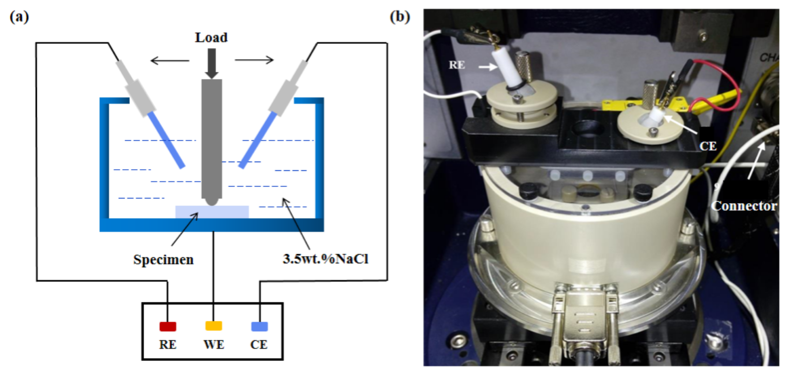
The tribocorrosion experiments of CoCrNi alloy sliding against Si3N4 were carried out in 3.5 wt.% NaCl solution under 4 N normal load. The changes of OCP overtime during the whole process are shown in Figure 2. The OCP remained in the stable range, and the CoCrNi surface was passivated for 10 min before the sliding. OCP rapidly shifts negatively after the slide begins. This is due to the fact that the passive film covering the surface of CoCrNi is destroyed under external load after the friction begins, exposing the fresh metal to the solution and increasing the corrosion tendency of the material [25,26]. As a mixed potential, OCP reflects the relative state of the passivated area and the non-passivated area, and its value depends on the integrity of the passivating film on the material surface [27]. The continuous negative shift of CoCrNi potential indicates that the rupture rate of passive film is greater than the regeneration rate, and depassivation is dominant in this condition. In addition, as can be seen from the time range from the 1800 s to 2000 s in Figure 2, the potential fluctuates seriously during friction but still keeps a declining trend. This is because, in the process of tribocorroison, the mechanical worn (depassivated) area is served as the anode, while the surrounding unworn (passive) areas are served as the cathode, resulting in galvanic coupling, which greatly increases the corrosion rate. After the sliding is finished, OCP starts to increase abruptly for the first 100 s and then more gradually reaches −0.28 V. As many reports have mentioned [28,29], this is a result of the reestablishment of damaged passive film on the worn surface [30,31,32]. In conclusion, the potential transfer of CoCrNi during tribocorroison is closely related to the integrity of the passive film. As a thermodynamic judgment basis for metal stability, the continuous negative potential shift indicates that the corrosion resistance of CoCrNi is reduced, which is a typical wear accelerated corrosion phenomenon.
OCP measurement enables gathering the electrochemical state of wear track and can easily evaluate the change of electrochemical state of the metal surface caused by rubbing. However, this measurement technique is insufficient for investigating corrosion kinetics upon friction, which can otherwise be completed by potentiodynamic polarization [19].
Then, the potentiodynamic polarization curves of CoCrNi under both static and corrosive wear conditions were measured and compared with commercial 316L stainless (Shanghai Lan Dong Industrial, Shanghai, China) steel and Inconel 600 (Shanghai Lan Dong Industrial, Shanghai, China). The corresponding electrochemical parameters obtained by extrapolation according to the standard Tafel were shown in Table 1. As can be seen from Figure 3, the three alloys showed a clear active-passive transition in both static and tribocorroison states in NaCl solution, and 316L stainless steel even exhibits secondary passivation under static conditions, The reason is that the passivation layer generated on the surface of 316L was unstable at the beginning, and the dissolution made the corrosion current density rise. The secondary passivation area indicated that the surface of 316L was passivated again. CoCrNi exhibits a wider passivation zone (438 mV) than that of 316L stainless steel (414 mV) and Inconel 600 (371 mV) under static conditions, indicating that the passivating film formed on the CoCrNi surface is more stable. From Table 1, the corrosion current density of Inconel 600 in the static state is 2.473 μA/cm2, about twice that in CoCrNi, suggesting that Inconel 600 has a faster corrosion rate and poor corrosion resistance compared with CoCrNi under static conditions.
The polarization curves under corrosive wear conditions can be used to analyze the corrosion rate and repassivation ability of metals after the passive film is mechanically damaged or removed [33]. It can be seen from Figure 3b that, compared with static conditions, the self-corrosion potential of the three alloys is shifted towards a cathodic direction under corrosive wear conditions, which is consistent with the results measured under OCP. In addition, the corrosion current density of the three alloys is found to increase significantly under tribocorrosion, indicating that the presence of wear accelerates corrosion to a further extent. When the potential in the anode region is below the pitting potential, metastable pits will be formed on the worn surface during sliding. The study of Burstein et al. [34,35] shows that the formation of metastable pits largely depends on the state of perforated cover composed of corrosion products and any remnant passive film over the pit mouth. In the process of tribocorroison, the perforated cover is repeated in a process of removal and regeneration due to mechanical sliding and passivation, making the concentration of chloride less than the required value for the growth of metastable pits (about 75% of saturation). This leads to a fluctuated current as shown in Figure 3b. By comparing Figure 3a,b, the potentiodynamic polarization curve of Inconel 600 showed a rapid increase in current density on the right side of Epit accompanied by violent current fluctuation, indicating the severe anodic dissolution of Inconel 600 in both conditions. It is worth noting that CoCrNi shows a very wide range of passivation zones (719 mV) during tribocorroison compared to 316L stainless steel (467 mV) and Inconel 600 (348 mV), further demonstrating the superior ability to maintain the passivation of CoCrNi.

3.2. Wear Behavior

Generally speaking, applied potential can change the tribological characteristics of the contact surface, which plays an important role in determining the tribocorrosion behavior of metals. Here, we will evaluate the tribocorroison resistance of the three alloys in the passivation state by exploring the wear volume and friction coefficient.
In view of the difference of the polarization curves of the three alloys under static conditions, the potentiostatic friction tests of CoCrNi and Inconel 600 at −0.2 V and CoCrNi and 316L SS at 0.1 V were compared to ensure a passivated surface state for all alloys. As can be seen from Figure 4a, at −0.2 V, the mass loss of CoCrNi is about 1/5 lower than that of Inconel 600, showing distinguished wear resistance. In addition, the average friction coefficient of CoCrNi (0.26) is also lower than that of Inconel 600 (0.31). Similarly, compared with 316L SS (Figure 4b), CoCrNi showed lower mass loss and friction coefficient at 0.1 V. By comparing Figure 4a,b, it can be seen that, as the applied potential changes from −0.2 V to 0.1 V, the total mass loss of CoCrNi increases by about three times. This is related to the formation of thick passive film on the surface of CoCrNi, which is easy to be destroyed or removed under external loading at high potential, resulting in the increased material loss reminiscent of corrosion accelerated wear. In conclusion, the comparison of friction coefficient and wear volume between the three alloys in the passivated state shows that CoCrNi has better tribological properties in 3.5 wt. % NaCl solution over the others.
To further systematically investigate the influence of potential on the tribocorrosion behavior of CoCrNi alloy in 3.5 wt.% NaCl, seven potentials (−0.8 V, −0.42 V, 0.2 V, OCP, 0 V, 0.1 V and 0.25 VAg/AgCl) were selected from potentiodynamic polarization curves, as indicated by Figure 3a. It must be pointed out that the seven potentials correspond to different surface states of CoCrNi, which is crucial to the analysis of tribocorrosion behaviors. To be specific, −0.8 V corresponds to a cathode potential, which inhibits the corrosion process and then the material loss only depends on the pure mechanical wear. In addition, −0.42 V is the self-corrosion potential of CoCrNi. Under this condition, bare metal will not spontaneously form a passive film nor will polarization occur. The other three potentials of −0.2 V, 0 V, and 0.1 V correspond to the three states at the beginning, middle, and end of the passivation process, respectively, and the anodic dissolution will occur on the alloy surface under a potential of 0.25 V.
Figure 5a shows the evolution of wear volume with different potentials in CoCrNi. It is obvious that the applied potential has a significant effect on the total material loss of CoCrNi alloy, and the wear volume increases with the applied potential. At −0.8 V, the CoCrNi wear volume is about 42,879 μm3, which is much lower than that under other potentials. There is little difference between the wear amount of CoCrNi under self-corrosion potential and OCP conditions. It is worth noting that, when the applied potential is −0.2 V, the total material loss is only 132,736 μm3, which is much lower than under the other two passive conditions of 0 V and 0.1 V (45,368 μm3 and 501,461 μm3). In anodic polarization tests, material loss is enhanced by the corrosive attack, and the synergistic effect between wear and corrosion results in high volume loss.
The evolutions COF with time are shown in Figure 5b for CoCrNi at different electrochemical states. The COF reaches a steady-state value exhibiting some peaks at fairly regular time intervals, especially at −0.8 V. Such fluctuations can be attributed to the formation and ejection of debris under pure mechanical wear. In addition, there is a general trend that COF decreases with the increasing potential. At −0.8 V, CoCrNi has a high friction coefficient of about 0.505 reflecting a mechanical wear-dominated friction process [36]. When the potential is −0.42 V, the friction coefficient decreases first and then stabilizes after the run-in stage, while under OCP, the friction coefficient increases gradually and then stabilizes. This difference of friction coefficient may be related to the passive film formed spontaneously on the CoCrNi surface under OCP conditions. At −0.2 V, the friction coefficient shows obvious undulation in the whole sliding process when compared with conditions at 0 V. This is probably associated with the insufficient passivation on CoCrNi at −0.2 V, but a continuous passive film can be formed at a higher potential. In the friction process, the passive films are easily removed at –0.2 V, and the recovery rate for the passive film is relatively slow (but still greater than that at OCP). The varied area ratio between the depassivated zone and the surrounding passivated zone in the wear track results in the undulation of the friction coefficient.
The morphologies of the wear track under seven applied potential conditions were further obtained via the 3D profilometer(NPFLEX, Bruker, Billerica, MA, USA). The depth and width of the wear track were shown in Figure 6 and summarized in Table 2. It has been found that the width and depth of wear track showed an increasing trend with the applied potential, which was consistent with the material loss as shown in Figure 5a. It is also worth noting that the wear depth marks increase significantly from −0.1 V to 0 V (from 1.99 μm to 3.34 μm), and the wear depth was five times larger for CoCrNi tested at 0.25 V when compared to the values at −0.8 V.

3.3. Morphologies and Component Analysis of the Worn Surfaces

The above results indicate that the deterioration of CoCrNi can be significantly affected by the surface chemical state. To further clarify the effect of potential, surface micrographs were explored after tribocorrosion tests. Figure 7a shows the overall morphology of the wear track of CoCrNi alloy at −0.8 V potential. It can be seen that CoCrNi forms a thin oxide layer on the wear mark under the condition of cathode polarization and distinct spallation is found as shown in the magnified images (Figure 7b–d). Some grooves and microcracks parallel to the sliding direction and a small amount of grinding debris can be observed on the surface (Figure 7e), which indicates that the wear mechanism under this condition mainly includes abrasive wear and oxidation wear. Grooves and spalling are caused by plastic deformation of CoCrNi during tribological load. Under the condition of strong cathodic polarization, corrosion is inhibited, and no protective passive film is formed on the CoCrNi surface. The formation of oxide film in this condition may be caused by the large amount of friction heat generated on the friction surface. The corresponding EDS of Figure 7a shows that the tribo-film is rich in O, Cr, and Si but depleted with Co and Ni, which indicates that the generated oxide film may be Cr oxide. In addition, the enrichment of Si in the oxides proves that the material transfer from Si3N4 counterpart occurs during the sliding process, which also indicates an adhesive wear and the impressive wear resistance of CoCrNi at this condition. XPS test results will be used to analyze the specific composition of the oxide layer.
The worn surface of CoCrNi tested at the self-corrosive potential is shown in Figure 8. By analyzing the characteristic areas in the wear tracks (Figure 8b,c), a large number of grooves parallel to the sliding direction are detected, indicating that abrasive wear is the main wear mechanism. In addition, driven by the shear stress upon periodic sliding, spalling caused by micro-cracks propagation and coalesce on the surface can also be observed. EDS results show that all elements in the wear track are evenly distributed without obvious segregation.
The worn surface of CoCrNi tested at OCP is shown in Figure 9. It can be seen from Figure 9b,c that a large number of furrows and a small amount of debris accumulation are found inside the wear track, indicating significant ductile deformation along with the grooves which were formed by counterface asperities plowing the surface. This suggested that abrasion was prevailing throughout sliding wear in the OCP condition. Obvious delamination was also found on the end face of the wear track (Figure 9d), which was a result of severe plastic deformation [37,38]. EDS mapping is performed on the wear track as shown in Figure 9d, and it found that the substrate material is rich in Co and Cr, while the surface film is rich in O, Si, and Ni. Under OCP conditions, the activation of surface metal elements will spontaneously produce a passive film, which is generally composed of metal oxide. According to EDS results, the passive film produced may be Ni oxide, which is different from the passive film produced under cathode polarization conditions (Figure 7). The Si element accumulated on the surface is a result of material transfer from Si3N4, indicating that adhesive wear is also one of the wear mechanisms of CoCrNi in this condition.
When the applied potential is −0.2 V, the surface of CoCrNi alloy has the same state as the initial stage of passivation. The metal anode loses its electrochemical activity and the anodic dissolution rate decreases. From the SEM image (Figure 10), it can be seen that delamination at the end of the wear scar was also examined, indicating that delamination wear was another primary mechanism for CoCrNi during sliding in 3.5wt. % NaCl solution. Combined with EDS results, it can also be seen that oxidation is dominated on the wear surface. In addition, there are a large number of corrosion products and wear debris in the inner area of the wear track (Figure 10c–e), which is due to the poor bearing capacity of the passive film formed on the CoCrNi surface, which breaks easily under the action of mechanical sliding and then accumulates inside the wear track.
Figure 11 shows the wear morphology of CoCrNi at 0.1 V applied potential. Under such conditions, the surface state of CoCrNi is in the transition from passivation to anodic dissolution. A large number of grooves and a few corrosion pits can be seen inside the wear track (Figure 11b). The EDS mapping analysis of the characteristic area of the wear track shows that the metal elements are evenly distributed, and there is obvious Si enrichment in the corrosion pits (Figure 11d). It should be noted that this Si aggregation is not a result of adhesive wear from the counter-body as mentioned earlier, but a phenomenon intimately related to the corrosion behavior. The large number of grooves produced at 0.1 V potential indicates that the wear mechanism is mainly abrasive wear.
Figure 12 shows the wear morphology of CoCrNi at 0.25 V applied potential. A large number of grooves and corrosion pits are the main features of wear scar under this condition (Figure 12b). When the applied potential was more positive than the pitting potential, a thick passive film is formed on the surface of CoCrNi, which reduces the shear stress during friction between the fiction pair and the metal matrix, leading to a reduced COF. However, this passive film is easily destroyed under the action of load and then dissolved in the corrosive medium in the form of wear debris, thereby accelerating the material loss. Under the high potential condition, the aggressive Cl in the solution will erode the passive film, resulting in many corrosion pits as shown in Figure 12c. These corrosion pits were scattered on CoCrNi surface and growing deeper into the inner material. EDS mapping of Figure 12d shows that the corrosion pits are rich in O and Cr while depleted in Co and Ni. Some Si elements are also attached to the surface of CoCrNi, which is consistent with the conclusion obtained under the condition of 0.1 V. The “cover” over the pit mouth, consisting of a remnant of the passive film and corrosion products, was very perforated and had poor adhesion, which would be peeled off readily when hard Si3N4 counterpart passed by. Thus, the occurrence of pitting corrosion must facilitate wear of CoCrNi although a low COF is reached in this condition.
Figure 13 presents the high-resolution XPS spectra of Ni 2p, Cr 2p, Co 2p, and O 1s recorded from the worn surface of CoCrNi alloy at the different potentials in 3.5 wt.% NaCl solution. After deconvolution analysis of each core-level spectrum, the valence states of concerned elements were identified. From Figure 13, similar patterns of these four elements can be found at different potentials. After friction, visible Co, Cr, and Ni elements were oxidized [39]. This is confirmed by the O 1s spectra, in that the curve can be divided into three peaks ascribed to oxide, hydroxide, and chemisorbed water, respectively. Therefore, the passive films formed at different potentials are composed of oxides, including NiO, Cr2O3, and CoO. For relative intensities of compounds from the high-resolution core-level spectrum of each element, several interesting results can be further discussed as follows. Firstly, the passive film at higher potential shows higher oxide and hydroxide content but chemisorbed water content, illustrating that a higher potential obviously enhances the oxidation and corrosion processes. Secondly, at the higher potential, the stable valence CoO amount decreases, and the intermediate valence Co3O4 amount increases. Thus, the electrochemical stability of passive film decreases. Thirdly, the Cr2O3 amount at 0.25 V increases significantly when compared with that of OCP. This suggests the acceleration of selective dissolution of Cr at higher potential, which may provide the channel for the permeation of Cl into the passive film. In summary, the stability of the passive film becomes weak at a higher potential, leading to a deteriorated corrosion resistance of CoCrNi.

3.4. Tribocorrosion Mechanism

The tribocorrosion mechanism of CoCrNi in 3.5 wt. % NaCl solution was investigated through SEM, EDS, and XPS analysis of wear track, and was combined with three kinds of electrochemical states, as shown in Figure 14. In Figure 14a, cathode polarization is achieved by applying cathode current in a three-electrode system and the cathodic reaction is dominated by the reduction of dissolved oxygen as [40,41]:
O2 + 2H2O + 4e → 4OH
Under the condition of cathodic polarization, the corrosion is inhibited, and mechanical wear dominates the tribocorrosion process with no synergistic effect between corrosion and wear. In fact, under the condition of cathode polarization, there is no passive film involved in the tribocorroison process, and the contact between the pin and the metal substrate is not uniform due to the difference of surface roughness, which leads to a higher friction coefficient and larger shear stress. Upon sliding, the heavy plastic deformation and fatigue loading on the surface produce a large number of micro-cracks, which then extend to the surface, causing a certain degree of spalling. Once the protective tribo-layer is detached from the contact surface, scratches and tearing of base material can also be examined (Figure 14a).
As shown in Figure 14b, in OCP conditions, the potentiostat only plays a role of monitoring the electrochemical signal in the process of tribocorroison. Similar to most passivated metals, CoCrNi exposed to 3.5 wt. % NaCl forms a passive film on the metal surface under the action of dissolved oxygen. Since the passivation and depassivation processes are dynamic, the removal and regeneration of passive film occur repeatedly during rubbing. As described by Celis et al. [40], the areas where the passive film is constantly destroyed and removed (worn area) act as the anode while the surrounding passivated areas (unworn area) act as a cathode, which forms a macroscopic galvanic cell and results in groove erosion. This will accelerate the corrosion of the wear zone and cause the mechanical properties of CoCrNi to deteriorate when compared with the case in the cathodic polarization condition. On the other hand, different from the tribocorrosion process in Figure 13a, there is no direct contact between the pin and the metal base in the OCP condition. The passive film formed on the surface of CoCrNi plays a certain role for lubrication here, which can be confirmed by the difference of friction coefficient between the cathodic polarization and OCP conditions in Figure 5b.
In Figure 14c, at anode polarization, CoCrNi surface forms a thicker passive film, which can greatly reduce the COF in the process of mechanical sliding (Figure 5b). The tribocorrosion process is similar to that in the OCP condition, where the passive film can be removed and regenerated quickly. However, driven by the high potential, the passivated CoCrNi alloy may still have a reaction with the aggressive Cl contained in the corrosion medium (reactions are displayed below). As shown in Figure 14c, the Cl ion with a small radius can more easily penetrate the passivation film to form chloride on CoCrNi, which is soluble in water. As a result, the passive film is partially dissolved, and the growth of passive film will be inhibited [42,43]. This process will destroy the dynamic equilibrium (e.g., dissolution and repassivation) at the surface, leading to pitting corrosion occurring inside the wear track (Figure 13):
M → Mn+ + ne (M: Co, Cr and Ni)
Mn+ + Cl + OH → MOCln−3 + H+
O2 + 2H2O + 4e → 4OH
Corrosion pits inside the wear track can therefore promote crack initiation and propagation resulting in accelerated wear.
In summary, at the cathodic potential, the corrosion dissolution of metal ions is negligible, and CoCrNi degradation is mainly through mechanical wear, which results in low volume loss. Under open circuit and anodic polarizing conditions, due to the occurrence of corrosion, the material loss of CoCrNi increased obviously compared with that under pure mechanical wear (cathodic polarization condition), demonstrating that the rate of material degradation could be controlled by external potentials. Furthermore, at 0 V potential, volume loss increased sharply and approached 448,934 um3 (Figure 5a), a rise of nearly 10 times that under pure mechanical wear (−0.8 V) due to the beginning of pitting corrosion. In this case, the synergistic effect between wear and corrosion results in high volume loss (Supplementary Material Figure S2). Clearly, corrosion has a significant effect on the degradation of CoCrNi during tribocorrosion, although it has excellent corrosion resistance in static conditions.

4. Conclusions

The degradation behavior of CoCrNi MEA in artificial seawater was systematically investigated in the present study. It was found that the sliding contact at CoCrNi surface leads to the cathodic shift of OCP, the increase of anodic current, and the accelerated wear loss. In addition, potentials play an important role in determining CoCrNi’s tribocorrosion behavior by changing the features of contact surfaces. The influence of electrochemical potential on tribocorrosion is then addressed in terms of the synergism between corrosion and wear, the correlation between COF and applied potentials, and, more importantly, the accelerated volume loss caused by anodic potentials. These phenomena are explained in detail by the formation and breakdown of oxide film during friction. Abrasive wear, adhesion, delamination, and plastic deformation were detected to be the predominant wear mechanism for CoCrNi at lower potential. At high applied potential, pitting corrosion occurred on the CoCrNi surface, and the generated pits became the preferred locations for wear, leading to a stronger synergy and accelerated material loss. This comprehensive investigation of the tribocorrosion mechanism of MEA will play a guiding role in its practical application and protection in seawater.

Supplementary Materials

The following are available online at https://www.mdpi.com/article/10.3390/met12030401/s1, Figure S1. XRD pattern of CoCrNi alloy. Figure S2. The proportion of mass fractions of C0, ∆C, W0 and ∆W in volume loss after CoCrNi friction corrosion for 40min under different potential conditions.

Author Contributions

Conceptualization, X.-Z.W., Y.W., Q.Z. and H.W.; Data curation, X.-Z.W., Y.W., Z.H., Q.Z. and H.W.; Formal analysis, Y.W. and Z.H.; Funding acquisition, Y.W.; Investigation, Y.W. and Z.H.; Methodology, X.-Z.W., Z.H., Q.Z. and H.W.; Writing—original draft, X.-Z.W.; Writing—review and editing, X.-Z.W., Q.Z. and H.W. All authors have read and agreed to the published version of the manuscript.

Funding

The authors would like to thank the Natural Science Foundation of China (Nos. 51901188 and 51801161) and the Fundamental Research Funds for the Central Universities (3102019JC001).

Institutional Review Board Statement

Not applicable.

Informed Consent Statement

Informed consent was obtained from all subjects involved in the study.

Data Availability Statement

Not applicable.
Conflicts of interest: The authors declare no conflict of interest.

References

  1. Yeh, J.W.; Chen, S.K.; Lin, S.J.; Gan, J.Y.; Chin, T.S.; Shun, T.T.; Tsau, C.H.; Chang, S.Y. Nanostructured high-entropy alloys with multiple principal elements novel alloy design concepts and outcomes. Adv. Eng. Mater. 2004, 6, 299–303. [Google Scholar] [CrossRef]
  2. Cantor, B.; Chang, I.T.H.; Knight, P.; Vincent, A.J.B. Microstructural development in equiatomic multicomponent alloys. Mater. Sci. Eng. A 2004, 375–377, 213–218. [Google Scholar] [CrossRef]
  3. Li, W.; Xie, D.; Li, D.; Zhang, Y.; Gao, Y.; Liaw, P.K. Mechanical behavior of high-entropy alloys. Prog. Mater. Sci. 2021, 118, 100777. [Google Scholar] [CrossRef]
  4. Zhang, Y.; Zuo, T.T.; Tang, Z.; Gao, M.C.; Dahmen, K.A.; Liaw, P.K.; Lu, Z.P. Microstructures and properties of high-entropy alloys. Prog. Mater. Sci. 2014, 61, 1–93. [Google Scholar] [CrossRef]
  5. George, E.P.; Raabe, D.; Ritchie, R.O. High-entropy alloys. Nat. Rev. Mater. 2019, 4, 515–534. [Google Scholar] [CrossRef]
  6. Fu, Y.; Li, J.; Luo, H.; Du, C.; Li, X. Recent advances on environmental corrosion behavior and mechanism of high-entropy alloys. J. Mater. Sci. Technol. 2021, 80, 217–233. [Google Scholar] [CrossRef]
  7. Otto, F.; Dlouhý, A.; Somsen, C.; Bei, H.; Eggeler, G.; George, E.P. The influences of temperature and microstructure on the tensile properties of a CoCrFeMnNi high-entropy alloy. Acta Mater. 2013, 61, 5743–5755. [Google Scholar] [CrossRef] [Green Version]
  8. Couzinié, J.P.; Lilensten, L.; Champion, Y.; Dirras, G.; Perrière, L.; Guillot, I. On the room temperature deformation mechanisms of a TiZrHfNbTa refractory high-entropy alloy. Mater. Sci. Eng. A 2015, 645, 255–263. [Google Scholar] [CrossRef]
  9. Zhang, M.; George, E.P.; Gibeling, J.C. Tensile creep properties of a CrMnFeCoNi high-entropy alloy. Scr. Mater. 2021, 194, 113633. [Google Scholar] [CrossRef]
  10. Laplanche, G.; Kostka, A.; Reinhart, C.; Hunfeld, J.; Eggeler, G.; George, E.P. Reasons for the superior mechanical properties of medium-entropy CrCoNi compared to high-entropy CrMnFeCoNi. Acta Mater. 2017, 128, 292–303. [Google Scholar] [CrossRef]
  11. Laplanche, G.; Kostka, A.; Horst, O.M.; Eggeler, G.; George, E.P. Microstructure evolution and critical stress for twinning in the CrMnFeCoNi high-entropy alloy. Acta Mater. 2016, 118, 152–163. [Google Scholar] [CrossRef] [Green Version]
  12. Rackwitz, J.; Yu, Q.; Yang, Y.; Laplanche, G.; George, E.P.; Minor, A.M.; Ritchie, R.O. Effects of cryogenic temperature and grain size on fatigue-crack propagation in the medium-entropy CrCoNi alloy. Acta Mater. 2020, 200, 351–365. [Google Scholar] [CrossRef]
  13. Yang, M.; Zhou, L.; Wang, C.; Jiang, P.; Yuan, F.; Ma, E.; Wu, X. High impact toughness of CrCoNi medium-entropy alloy at liquid-helium temperature. Scr. Mater. 2019, 172, 66–71. [Google Scholar] [CrossRef]
  14. Hua, D.; Xia, Q.; Wang, W.; Zhou, Q.; Li, S.; Qian, D.; Shi, J.; Wang, H. Atomistic insights into the deformation mechanism of a CoCrNi medium entropy alloy under nanoindentation. Int. J. Plast. 2021, 142, 102997. [Google Scholar] [CrossRef]
  15. Zhu, M.; He, F.; Yuan, Y.; Guo, S.; Wei, G. A comparative study on the corrosion behavior of CoCrNi medium-entropy alloy and 316L stainless steel in simulated marine environment. Intermetallics 2021, 139, 107370. [Google Scholar] [CrossRef]
  16. Pan, S.; Zhao, C.; Wei, P.; Ren, F. Sliding wear of CoCrNi medium-entropy alloy at elevated temperatures: Wear mechanism transition and subsurface microstructure evolution. Wear 2019, 440–441, 203108. [Google Scholar] [CrossRef]
  17. Guo, X.; Baker, I.; Kennedy, F.E.; Song, M. A comparison of the dry sliding wear behavior of NiCoCr medium entropy alloy with 316 stainless steel. Mater. Charact. 2020, 160, 110132. [Google Scholar] [CrossRef]
  18. Li, Z.Y.; Yu, Z.Y.; He, X.F.; Yang, S.D. The development and perspective of water hydraulics. Proc. JFPS Int. Symp. Fluid Power 1999, 1999, 335–342. [Google Scholar] [CrossRef]
  19. Chen, J.; Wang, J.; Yan, F.; Zhang, Q.; Li, Q.-a. Effect of applied potential on the tribocorrosion behaviors of Monel K500 alloy in artificial seawater. Tribol. Int. 2015, 81, 1–8. [Google Scholar] [CrossRef]
  20. Hong, M.H.; Pyun, S.I. Corrosive wear behaviour of 304-L stainless steel in 1 N H2SO4 solution Part 1. Effect of applied potential. Wear 1991, 147, 59–67. [Google Scholar] [CrossRef]
  21. Zhang, Y.; Yin, X.-Y.; Yan, F.-Y. Tribocorrosion behaviour of type S31254 steel in seawater: Identification of corrosion–wear components and effect of potential. Mater. Chem. Phys. 2016, 179, 273–281. [Google Scholar] [CrossRef]
  22. Yahagi, Y.; Mizutani, Y. Corrosive Wear of Carbon and Austenitic Stainless-Steels in Nacl Solution. Wear 1986, 110, 401–408. [Google Scholar] [CrossRef]
  23. Zhang, Y.; Yin, X.; Wang, J.; Yan, F. Influence of potentials on the tribocorrosion behavior of 304SS in artificial seawater. RSC Adv. 2014, 4, 55752–55759. [Google Scholar] [CrossRef]
  24. Du, Y.; Zhou, Q.; Jia, Q.; Shi, Y.; Wang, H. Imparities of shear avalanches dynamic evolution in a metallic glass. Mater. Res. Lett. 2020, 8, 357–363. [Google Scholar] [CrossRef]
  25. Vieira, A.C.; Rocha, L.A.; Papageorgiou, N.; Mischler, S. Mechanical and electrochemical deterioration mechanisms in the tribocorrosion of Al alloys in NaCl and in NaNO3 solutions. Corros. Sci. 2012, 54, 26–35. [Google Scholar] [CrossRef] [Green Version]
  26. Stojadinović, J.; Bouvet, D.; Declercq, M.; Mischler, S. Effect of electrode potential on the tribocorrosion of tungsten. Tribol. Int. 2009, 42, 575–583. [Google Scholar] [CrossRef]
  27. Pina, V.G.; Amigó, V.; Muñoz, A.I. Microstructural, electrochemical and tribo-electrochemical characterisation of titanium-copper biomedical alloys. Corros. Sci. 2016, 109, 115–125. [Google Scholar] [CrossRef]
  28. Chen, J.; Zhang, Q.; Li, Q.-a.; Fu, S.-l.; Wang, J.-z. Corrosion and tribocorrosion behaviors of AISI 316 stainless steel and Ti6Al4V alloys in artificial seawater. Trans. Nonferrous Met. Soc. China 2014, 24, 1022–1031. [Google Scholar] [CrossRef]
  29. Ponthiaux, P.; Wenger, F.; Drees, D.; Celis, J.P. Electrochemical techniques for studying tribocorrosion processes. Wear 2004, 256, 459–468. [Google Scholar] [CrossRef]
  30. Liu, X.; Zhao, X.; An, Y.; Hou, G.; Li, S.; Deng, W.; Zhou, H.; Chen, J. Effects of loads on corrosion-wear synergism of NiCoCrAlYTa coating in artificial seawater. Tribol. Int. 2018, 118, 421–431. [Google Scholar] [CrossRef]
  31. Mahdi, E.; Rauf, A.; Eltai, E.O. Effect of temperature and erosion on pitting corrosion of X100 steel in aqueous silica slurries containing bicarbonate and chloride content. Corros. Sci. 2014, 83, 48–58. [Google Scholar] [CrossRef]
  32. Sinnett-Jones, P.E.; Wharton, J.A.; Wood, R.J.K. Micro-abrasion–corrosion of a CoCrMo alloy in simulated artificial hip joint environments. Wear 2005, 259, 898–909. [Google Scholar] [CrossRef]
  33. Li, Z.; Yu, H.; Sun, D. The tribocorrosion mechanism of aluminum alloy 7075-T6 in the deep ocean. Corros. Sci. 2021, 183, 109306. [Google Scholar] [CrossRef]
  34. Burstein, G.T.; Pistorius, P.C.; Mattin, S.P. The Nucleation and Growth of Corrosion Pits on Stainless-Steel. Corros. Sci. 1993, 35, 57–62. [Google Scholar] [CrossRef]
  35. Burstein, G.T.; Sasaki, K. The birth of corrosion pits as stimulated by slurry erosion. Corros. Sci. 2000, 42, 841–860. [Google Scholar] [CrossRef]
  36. Zhou, Q.; Han, W.; Luo, D.; Du, Y.; Xie, J.; Wang, X.-Z.; Zou, Q.; Zhao, X.; Wang, H.; Beake, B.D. Mechanical and tribological properties of Zr–Cu–Ni–Al bulk metallic glasses with dual-phase structure. Wear 2021, 474–475, 203880. [Google Scholar] [CrossRef]
  37. Bhardwaj, V.; Zhou, Q.; Zhang, F.; Han, W.; Du, Y.; Hua, K.; Wang, H. Effect of Al addition on the microstructure, mechanical and wear properties of TiZrNbHf refractory high entropy alloys. Tribol. Int. 2021, 160, 107031. [Google Scholar] [CrossRef]
  38. Luo, D.; Zhou, Q.; Ye, W.; Ren, Y.; Greiner, C.; He, Y.; Wang, H. Design and characterization of self-lubricating refractory high entropy alloy-based multilayered films. Appl. Mater. Interfaces 2021, 13, 55712–55725. [Google Scholar] [CrossRef]
  39. Liu, Y.; Zhang, F.; Huang, Z.; Zhou, Q.; Ren, Y.; Du, Y.; Wang, H. Mechanical and dry sliding tribological properties of CoCrNiNb medium-entropy alloys at room temperature. Tribol. Int. 2021, 163, 107160. [Google Scholar] [CrossRef]
  40. Celis, J.P.; Ponthiaux, P.; Wenger, F. Tribo-corrosion of materials: Interplay between chemical, electrochemical, and mechanical reactivity of surfaces. Wear 2006, 261, 939–946. [Google Scholar] [CrossRef]
  41. Zhang, Y.; Yin, X.; Yan, F. Effect of halide concentration on tribocorrosion behaviour of 304SS in artificial seawater. Corros. Sci. 2015, 99, 272–280. [Google Scholar] [CrossRef]
  42. Strehblow, H.H.; Titze, B. Pitting potentials and inhibition potentials of iron and nickel for different aggressive and inhibiting anions. Corros. Sci 1977, 17, 461–472. [Google Scholar] [CrossRef]
  43. Kolotyrkin, J.M. Pitting corrosion of metals. Corros. Sci. 1963, 19, 261–268. [Google Scholar] [CrossRef]
Figure 1. Schematic view (a) and some components (b) of the tribocorrosion tester.
Metals 12 00401 g001
Figure 2. OCP curve of CoCrNi before (10 min), during (40 min), and after (10 min) rubbing with Si3N4 at 4 N normal loads. The insert map is the enlarged view presenting the details of the OCP curve.
Metals 12 00401 g002
Figure 3. Potentiodynamic polarization curves of 316L stainless steel, Inconel 600, and CoCrNi rubbing against Si3N4 in 3.5 wt.% NaCl solution under (a) static corrosion and (b) tribocorrosion.
Metals 12 00401 g003
Figure 4. Comparison of friction coefficient and wear volume of CoCrNi in 3.5 wt.% NaCl solution with (a) Inconel 600 at −0.2 V and (b) 316L stainless steel at 0.1 V. Sliding speed and time are 1 mm/s and 40 min, respectively.
Metals 12 00401 g004
Figure 5. Wear volume (a) and friction Coefficient (b) of CoCrNi in 3.5 wt. % NaCl Solution under different applied potentials.
Metals 12 00401 g005
Figure 6. The three-dimensional image of the worn surface of CoCrNi in 3.5 wt. % NaCl solution under different applied potential conditions, −0.8 V (a), −0.42 V (b), OCP (c), 0.2 V (d), 0 V (e), 0.1 V (f), 0.25 V (g).
Metals 12 00401 g006
Figure 7. SEM and EDS micrographs of overall morphology (a) and some details (b-f) of the wear track for CoCrNi tested in 3.5 wt. % NaCl solution at −0.8 V applied potential.
Metals 12 00401 g007
Figure 8. SEM and EDS micrographs of overall morphology (a) and some details (b-d) of the wear track for CoCrNi tested at an applied potential of −0.42 V.
Metals 12 00401 g008
Figure 9. SEM and EDS micrographs of overall morphology (a) and some details (b-d) of the wear track for CoCrNi tested at OCP.
Metals 12 00401 g009
Figure 10. SEM and EDS micrographs of overall morphology (a) and some details (b-d) of the wear track for CoCrNi tested at an applied potential of −0.2 V.
Metals 12 00401 g010
Figure 11. SEM and EDS micrographs of overall morphology (a) and some details (b and c) of the wear track for CoCrNi tested at an applied potential of 0.1 V.
Metals 12 00401 g011
Figure 12. SEM and EDS micrographs of overall morphology (a) and some details (b-d) of the wear track for CoCrNi tested at an applied potential of 0.25 V.
Metals 12 00401 g012
Figure 13. XPS spectrum of the worn surface of CoCrNi tested at different applied potentials.
Metals 12 00401 g013
Figure 14. Schematic diagram of tribocorrosion mechanism at (a) cathodic polarization, (b) OCP, and (c) anodic dissolution state of CoCrNi alloy in 3.5 wt. % NaCl.
Metals 12 00401 g014
Table 1. Triboelectrochemical parameters of three alloys under both static and tribocorroison state in 3.5 wt.%NaCl solution.Ecorr: self-corrosion potential; Epit: pitting potential; icorr: corrosion current density; βc and βa: cathodic and anodic slopes.
SampleConditionEcorr
(VAg/AgCl)
Epit
(VAg/AgCl)
icorr
(μA/cm2)
βc
(mV/dec)
βa
(mV/dec)
316LStatic−0.3160.1681.209−104.38245.01
Silding−0.3650.1823.120−1876.50621.86
Inconel
600
Static−0.4480.0212.473−275.62558.21
Silding−0.5020.0042.605−208.40451.97
CoCrNiStatic−0.4410.0821.064−153.32240.87
Silding−0.4790.4232.144−160.26215.58
Table 2. Depth and width of wear tracks of CoCrNi under different applied potentials.
Applied Potential (V)−0.8 V−0.42 VOCP−0.1 V0 V0.1 V0.25 V
Wear depth (μm)0.931.311.851.993.344.004.62
Wear width (μm)209.76216.51220.55223.66254.89281.65314.64
Publisher’s Note: MDPI stays neutral with regard to jurisdictional claims in published maps and institutional affiliations.

