Article

Observation of Microstructure and Mechanical Properties in Heat Affected Zone of As-Welded Carbon Steel by Using Plasma MIG Welding Process

by
Sarizam Mamat
1,
Nur Azmina Sidek
1,
Nur Aina Aqilah Mohd Afandi
1,
Rose Alifah Ellyana Roslan
1,
Teo Pao Ter
1,
Toshifumi Yuji
2,
Shinichi Tashiro
3,* and
Manabu Tanaka
3
1
Advanced Materials Research Cluster, Faculty of Bioengineering and Technology, Universiti Malaysia Kelantan, Jeli Campus, Jeli 17600, Malaysia
2
Faculty of Education, University of Miyazaki, 1-1 Gakuenkibanadai-Nishi, Miyazaki 889-2192, Japan
3
Joining and Welding Research Institute, Osaka University, Osaka 567-0047, Japan
*
Author to whom correspondence should be addressed.
Metals 2022, 12(2), 315; https://doi.org/10.3390/met12020315
Submission received: 12 January 2022 / Revised: 29 January 2022 / Accepted: 4 February 2022 / Published: 10 February 2022

Abstract

:
Plasma MIG welding is a hybrid welding process that combines two welding methods of conventional metal inert gas (MIG) welding with plasma arc welding. This study investigates the effect of plasma and plasma current values on the microstructure and microhardness properties of welded carbon steel plates. It was found that utilization of the plasma has resulted in a refined microstructure in the heat affected zones (HAZ), and a decrease in microhardness values as compared to conventional MIG welds. This potentially increases the ductility of the plasma MIG weldments. Furthermore, decreasing the plasma currents would result in the decrease of microhardness and grain sizes, thus further increasing the ductility of the welds.

1. Introduction

Gas metal arc welding (GMA), also known as metal inert gas (MIG) welding, is a common method for joining various metals, such as carbon steel, aluminum and stainless steel. It is a highly reliable and cost-effective technique, with high speeds and productivity [1]. However, the unstable arc of the MIG process causes low weld penetration and high spatter generation [2]. To overcome this limitation, several hybrid methods have been developed to enhance the MIG process. M. Gao et al. has studied the CO2 laser—MIG hybrid welding to relate the melting energy and heat source interaction. The report showed that the hybridization increased the melting energy up to 23% compared to the individual welding process [3]. Further studied on microstructure characteristics of the welded steel by using laser—MIG hybrid welding found that the laser zone affects the microstructure grain size to be finer and narrower heat affected zone (HAZ) compared to the GMA arc zone due to the difference of temperature gradient [4]. Meanwhile, S. Kanemaru et al. studied the tungsten inert gas (TIG)—MIG hybrid welding and the report confirmed the higher quality and efficiency compared to the conventional MIG welding [5,6]. The hybridization of TIG—MIG welding also capable to reduce the welding defect such as undercut as reported by Ran Zong et al. [7]. The above aforementioned hybridization of welding processes was developed individually and combined to contemplate the advantages of each process.
The development of plasma MIG welding is the hybrid welding process that realizes the plasma welding and MIG welding in a single torch [8]. This is a promising technology that utilizes the merits of plasma arc and MIG welding processes [8]. A recent study on plasma MIG has shown that the total heat input into base metal can be controlled through reduction of metal droplet temperature [9]. However, the plasma flow surrounding the MIG arc reduces the cooling rate at the weld zone. The combination of these two factors of total heat input and cooling rate influences the microstructure formation in weld as well as in the heat affected zone (HAZ) [10,11]. Thus, by using the plasma MIG welding system, the microstructure formation and sizes at the HAZ can be controlled, which leads to improvements in mechanical properties of the area [12].
In this study, the effects of plasma current in the plasma MIG welding process on the microstructure refinement and mechanical properties of the HAZ were evaluated. The observation was made on the microstructure at the HAZ for as-welded SPCC steel weldments using optical microscopy and electron backscatter diffraction (EBSD). The mechanical properties of the weldments were determined by Vickers micro-hardness tests. Comparisons would be made with conventional MIG welding to determine the effect of plasma and plasma currents on the microstructure and mechanical properties of the welds.

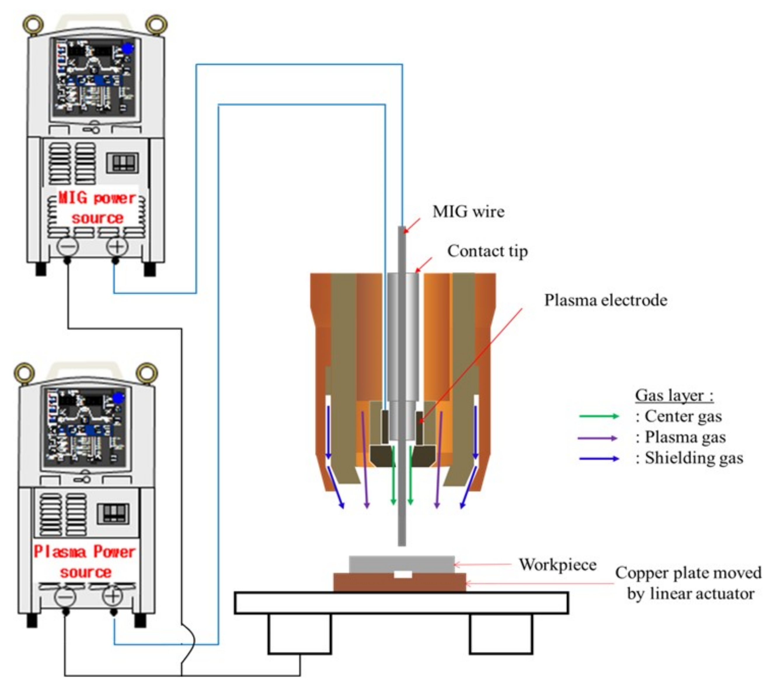
2. Experimental Method

In this study, a bead-on-plate weld was conducted on a 4 mm thick commercial cold rolled steel plate, SPCC steel (TP Giken Co. Ltd., Osaka, Japan) using a 1.2 mm diameter mild steel wire, YGW11 (Kobelco, Japan). Figure 1 shows the schematic of the plasma MIG welding system used, comprising of a plasma power source and a specially designed hybrid torch, which allows the system to operate either in normal MIG or plasma MIG modes. The chemical compositions of the SPCC steel and filler wire are listed in Table 1 and Table 2, respectively. Table 3 lists the values for the constant welding parameters of the wire feeding speed, welding speed, contact tip to work distance and the MIG voltage. Argon gas was supplied into all three layers at flow rates of 5 L/min (center gas), 10 L/min (plasma gas) and 10 L/min (shielding gas) from three different gas cylinders. The welds were conducted for plasma currents of DC25 A, DC50 A, DC75 A and DC100 A. For comparison purposes, conventional MIG welding tests were also conducted using the same plasma MIG welding system, with the plasma current disabled. A two-color temperature measurement method was used to measure the weld bead temperatures during welding [13].
Cross-sections of the resultant welds were micrographically prepared by grinding and polishing to a mirror surface and etched using nital 2%. The microstructures of the specimen were analyzed using optical microscopy (Meiji Techno Model IM7530, Meiji Techno, Miyoshi, Japan) and EBSD (Hitachi Model NB5000, HITACHI High-Tech Co., Hitachi, Japan). The mechanical properties of the weldments were investigated using a Vickers Hardness Tester (Mitutoyo HM-200, Aurora, IL, UAS).

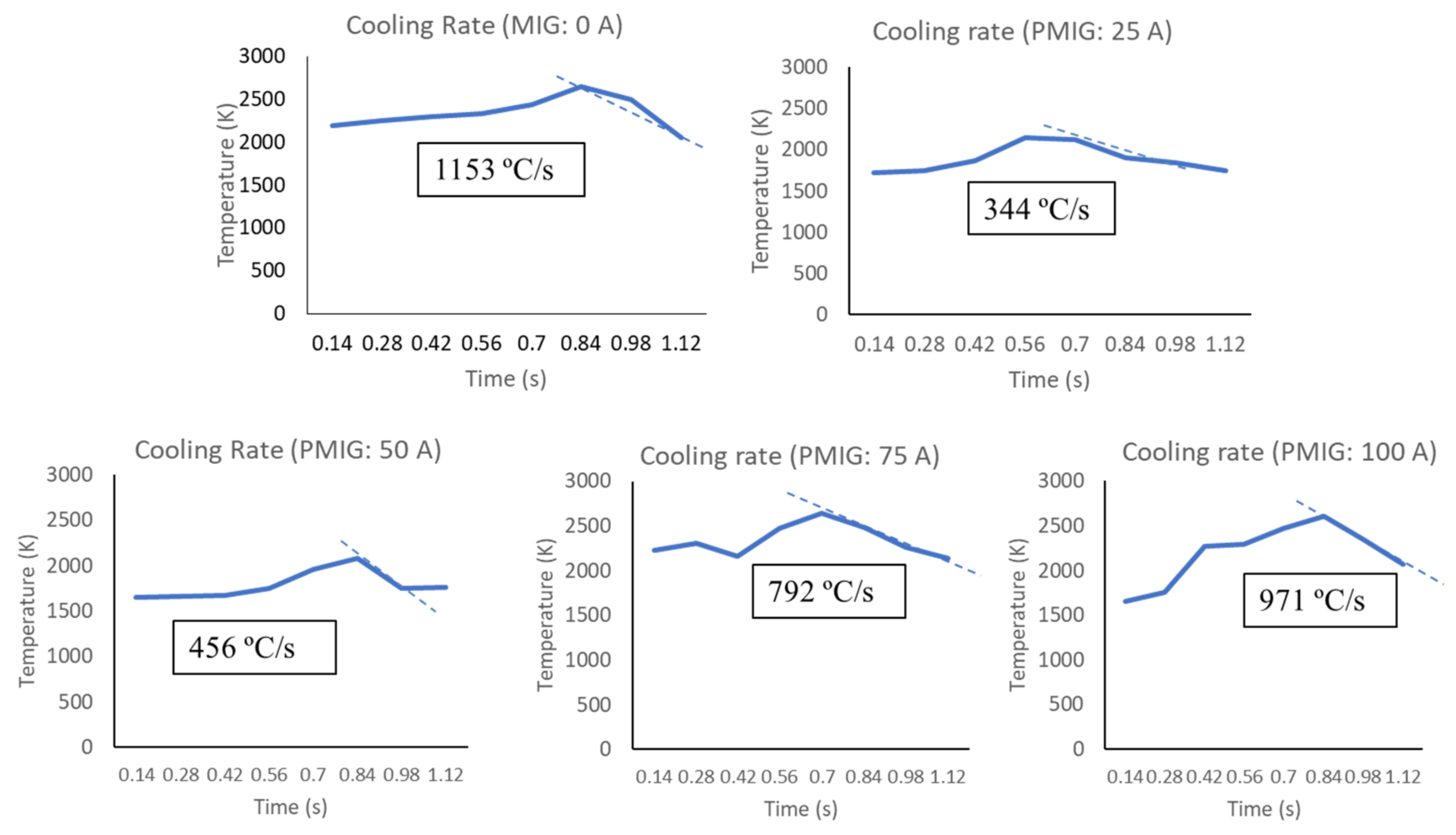
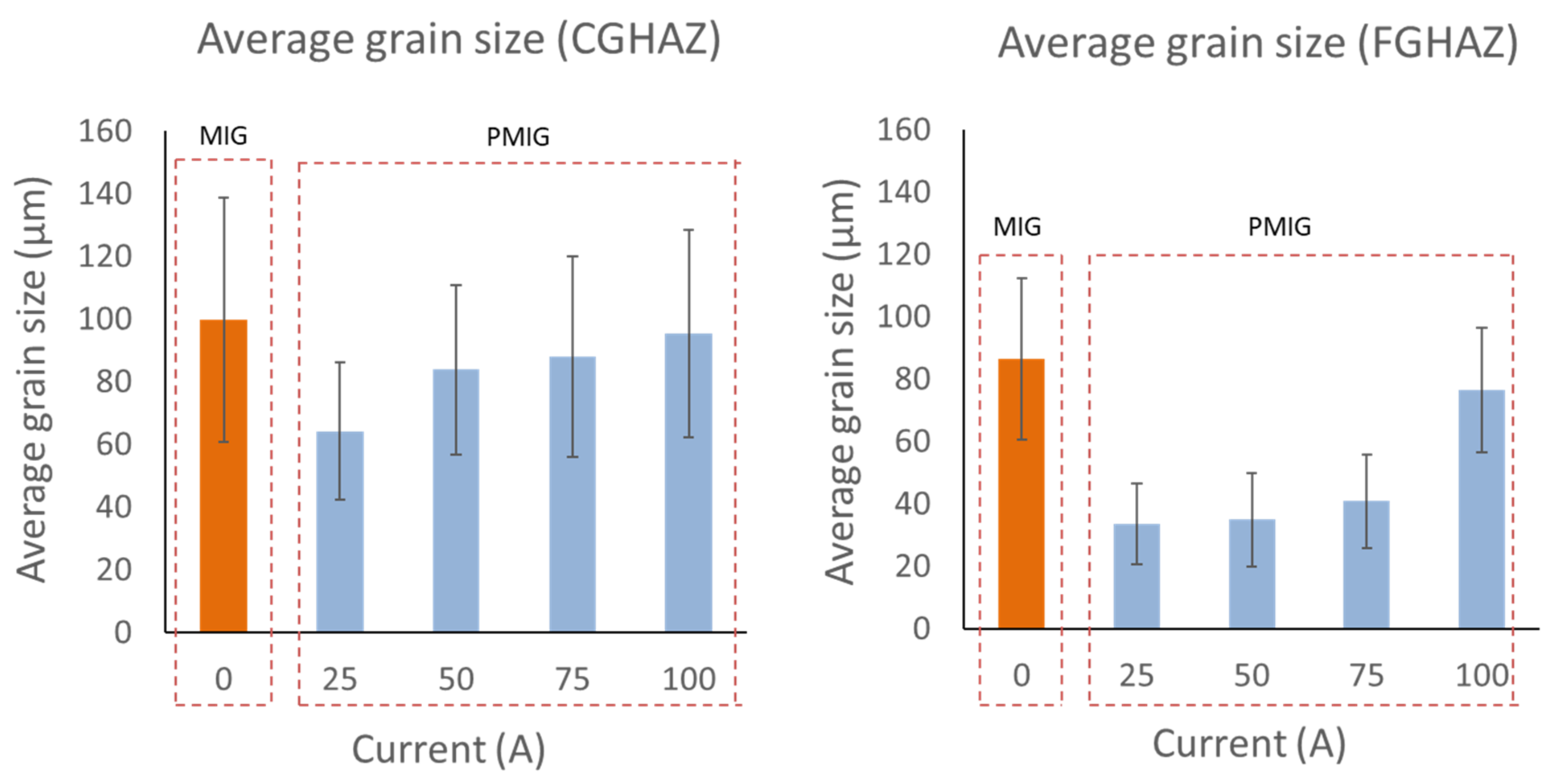
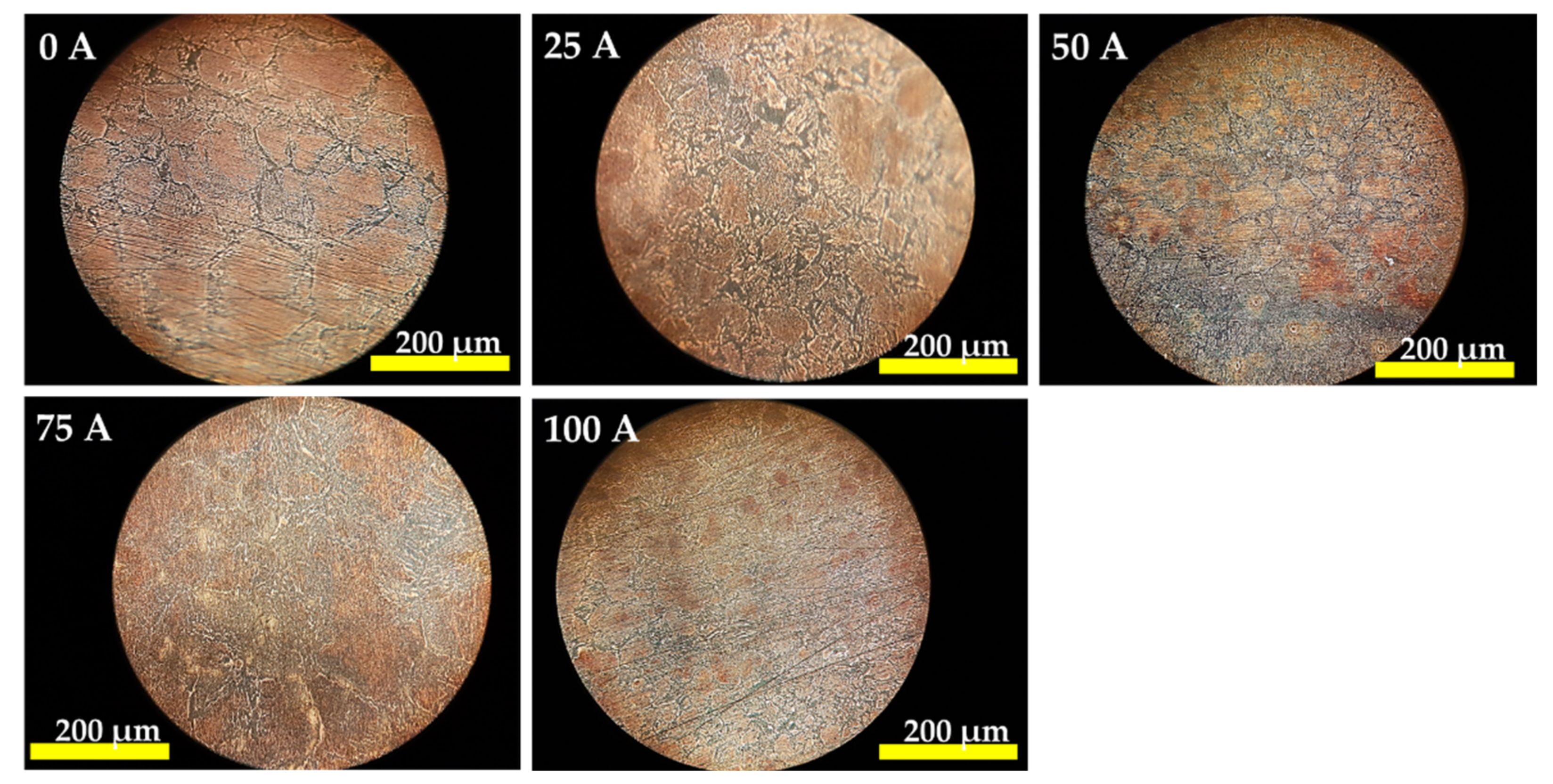
3. Results and Discussion

In general, it was seen that the plasma current influences the width of the HAZ. Table 4 shows that as the plasma current increases, the width of the HAZ would also increase. The change in the HAZ width suggests that the plasma current contributes to the increase of heat input into the base metal. The increase of plasma current also increases the weld bead size of the specimen. This suggests that the presence of plasma flow with increasing of plasma current improves the melting rate of the welding wire.
Microscopic analysis of the coarse grain HAZ (CGHAZ) region shows the grain boundaries at the area of each 0 A, 25 A, 50 A, 75 A and 100 A under microscope at 20× magnification, as shown in Figure 2. It was seen that finer grain structures were obtained for plasma currents of 25 A, 50A, and 75 A as compared to 100 A and conventional MIG welding. The finer grain structures in plasma MIG welding is believed due to the low heat input into base metal during welding as a consequence of the lower droplet temperature as a result of the presence of plasma flow in plasma MIG welding process [9].
During the welding process, the weld bead temperature is measured by using a two-color temperature measurement method [13]. Figure 3 shows the analysis of the weld pool temperatures for different plasma currents. The temperature measurement was carried out immediately after the arc eliminated. The weld pool temperature of conventional MIG welding (0 A plasma current) was 2287 K, while for plasma MIG welding the measured weld pool temperatures for 25, 50, 75 and 100 A plasma currents were 1864, 1845, 1896 and 1885 K, respectively. Thus, the temperature difference between 100 A plasma MIG and conventional MIG was approximately 400 K. This suggests that the higher peak temperature of weld pool in conventional MIG welding result in a coarser grain structure. The results also show the good agreement with the previous result in Figure 2.
Heat transferred to the workpiece during welding may originate from radiation, convection and conduction modes. In conventional arc welding, the heat from the arc accounts for the largest part of the heat transferred. The heat input originates from the molten filler metal, as is then transferred to the workpiece as the molten bead is dropped and spreads on the surface of the weld metal. However, in plasma MIG welding, the combination of two weld heat sources (plasma arc welding and MIG welding) enables the formation of an inner (MIG) and outer (plasma) arc sources, resulting in variations in the heat input. This heat input can be varied by altering the current and voltage values. In the plasma MIG welding, the heat input into the workpiece was reduced as the current did not flow through the workpiece but is collected by the lower nozzle instead [15].
In this study, it was found that regardless of MIG current or plasma current selection, a high current value increases the heat input of the carbon steel weld metal. The increase in heat input increases the welding temperature and size of the weld bead formed. Heat input can influence the cooling rate, which may affect the mechanical properties and metallurgical structure of the weld metal and the HAZ. It was found that increase in the heat input reduces the hardness and strength values of the welded steel.
It was found that a stable weld bead formation was obtained for plasma MIG as compared to conventional MIG. This could be due to the reduction in the cooling rate during solidification, as the plasma flow has enveloped the weld bead during solidification. Figure 4 shows a graph of temperature versus time which represents the cooling rate.
Figure 5 shows the inverse pole figure (IPF) map for the specimen welded by conventional MIG welding (plasma current 0 A) and by plasma MIG welding with 25, 50, 75 and 100 A of plasma current. The black lines shown in the figures represent the boundary lines of the weld metal (WM), the CGHAZ, and the FGHAZ. The grain sizes in the CGHAZ of conventional MIG welding (0 A plasma current) was larger than the grain size welded by 25, 50 and 100 A plasma current. In the plasma MIG welds, the grain sizes in the CGHAZ and FGHAZ regions of the as-welded steel were almost similarly sized, thus making it difficult to distinguish the boundaries between these areas. The reduction in the cooling rate during solidification is believed to affects the refinement of the CGHAZ regions.
20 grains at each CGHAZ and FGHAZ region were calculated by using the Image J software and the average value of the grain size for the different plasma currents are shown in Figure 6. The largest average grain size in the CGHAZ was obtained for conventional MIG welding (0 A plasma current) at 99.699 µm. For plasma-MIG welding, the grain sizes were 64.106 µm, 83.756 µm, 87.801 µm and 95.267 µm for plasma currents of 25 A, 50 A, 75 A and 100 A, respectively. Similar trends were recorded for FGHAZ at average grain sizes of 86.326 µm for the conventional MIG (0 A plasma current), and grain sizes of 33.442 µm, 34.834 µm, 40.721 µm, and 76.322 µm for the plasma currents of 25, 50, 75 and 100 A, respectively. This shows that in general, the application of plasma currents reduces the grain sizes of the HAZ as compared to MIG welds, and decreasing the plasma current would further decrease the grain sizes.
Vickers microhardness tests were performed at the FZ (fusion zone), HAZ and the base metal of the as-welded carbon steel. The highest microhardness value of 196 Hv was obtained for conventional MIG welding (plasma current 0 A). Figure 7 shows the distribution of the microhardness values at the HAZ, weld metal (WM) and the base metal (BM), indicating that all samples have higher hardness values in the weld zone than the base metal. The higher weld bead temperature and higher cooling rate in conventional MIG welding coarsened the microstructure at CGHAZ. The lower heat input causes the finer microstructure and promotes the formation of low temperature microstructure [16]. This phenomenon results in the higher hardness of the specimen welded by conventional MIG welding. On the other hand, in plasma MIG welding, the lower weld bead temperature and lower cooling rate results in the suppression of the grain growth, thus refines the grain. The lower cooling rate hindered the formation of low temperature microstructure, thus reduce the hardness value at the area.
Meanwhile, the difference of the base metal’s hardness of the specimen welded by using conventional MIG welding (0 A plasma current) and 100 A of plasma MIG welding is mainly due to the difference of the weld bead size of both specimens compared with the others. The hardness value at the distance 10 mm from the weld center is believed yet to be in HAZ region.

4. Conclusions

It was seen that the use of plasma MIG welding process has resulted in the refinement of the microstructure in the CGHAZ region, thus improving the mechanical properties of the as-welded SPCC steel. The highest microhardness values were obtained for conventional MIG in the CGHAZ regions. Incorporation of the plasma arc reduces the hardness, potentially increasing the ductility of the joining by plasma MIG welds. Further reduction in hardness can be obtained by decreasing the plasma current values.

Author Contributions

Conceptualization, methodology, writing, supervision, S.M.; experiment; N.A.S. and N.A.A.M.A.; discussion, S.M., N.A.S., N.A.A.M.A., R.A.E.R., T.P.T., T.Y., S.T. and M.T. All authors have read and agreed to the published version of the manuscript.

Funding

This research received a financial support of the Malaysia Government through FRGS RACER grant (RACER/1/2019/TK03/UMK//1) and JWRI International Joining Research Collaboration 2018 from Osaka University, Japan.

Data Availability Statement

Data can be available based on the requirements to verify this work.

Acknowledgments

The author gratefully acknowledges the financial support of the Malaysia Government through FRGS RACER grant (R/FRGS/A1300/00896A/003/2019/00669) and JWRI International Joining Research Collaboration 2018 from Osaka University, Japan.

Conflicts of Interest

The authors declare no conflict of interest.

References

  1. Sen, M.; Mukherjee, M.; Pal, T.K. Evaluation of correlations between DP-GMAW process parameters and bead geometry. Weld. J. 2015, 94, 265s–279s. [Google Scholar]
  2. Modenesi, P.J.; Nixon, J.H. Arc instability phenomena in GMA welding. Weld. Res. Suppl. 1994, 9, 219s–224s. [Google Scholar]
  3. Gao, M.; Zeng, X.Y.; Hu, Q.W. Effects of welding parameters on melting energy of CO2 laser—GMA hybrid welding. Sci. Technol. Weld. Join. 2006, 11, 517–522. [Google Scholar] [CrossRef]
  4. Gao, M.; Zeng, X.; Yan, J.; Hu, Q. Microstructure characteristics of laser—MIG hybrid welded mild steel. Appl. Surf. Sci. 2008, 254, 5715–5721. [Google Scholar] [CrossRef]
  5. Kanemaru, S.; Sasaki, T.; Sato, T.; Mishima, H.; Tashiro, S.; Tanaka, M. Study for TIG—MIG hybrid welding process. Weld World 2014, 58, 11–18. [Google Scholar] [CrossRef]
  6. Kanemaru, S.; Sasaki, T.; Sato, T.; Era, T.; Tanaka, M. Study for the mechanism of TIG—MIG hybrid welding process. Weld World 2015, 59, 261–268. [Google Scholar] [CrossRef]
  7. Zong, R.; Chen, J.; Wu, C. A comparison of TIG—MIG hybrid welding with conventional MIG welding in the behaviors of arc, droplet and weld pool. J. Mater. Processing Tech 2019, 270, 345–355. [Google Scholar] [CrossRef]
  8. Ono, K.; Lie, Z.; Era, T.; Ueono, T.; Ueyama, T.; Tanaka, M.; Nakata, K. Development of a plasma MIG welding system for aluminum. Weld. Int. 2019, 23, 805–809. [Google Scholar] [CrossRef]
  9. Bin Mamat, S.S.; Tashiro, M.; Tanaka, M. Study on factors affecting the droplet temperature in plasma MIG welding process. J. Phys. D. Appl. Phys. 2018, 51, 135206. [Google Scholar] [CrossRef]
  10. Tsujimura, Y.; Tanaka, M. Numerical Simulation of heat source property with metal vapor behavior in GMA Welding. J. Japan Weld. Soc. 2012, 30, 68–76. (In Japanese) [Google Scholar] [CrossRef] [Green Version]
  11. Valensi, F.; Pellerin, S.; Castillon, Q.; Boutaghane, A.; Dzierzega, K.; Zielinska, S.; Pellerin, N.; Briand, F. Study of the spray to globular transition in gas metal arc welding: A spectroscopic investigation. J. Phys. D Appl. Phys. 2013, 46, 1–12. [Google Scholar] [CrossRef]
  12. Mamat, S.; Afandi, A.A.M.; Abu Bakar, M.B.; Masri, M.N.; Mohamed, M.; Abdul Razab, M.K.A.; Yuji, T.; Tashiro, S.; Tanaka, M. Effect of plasma flow in plasma mig welding process to the microstructure refinement at heat affected zone of as-welded carbon steel. Mater. Sci. Forum 2020, 1010, 15–20. [Google Scholar] [CrossRef]
  13. Long, N.P.; Katada, Y.; Tanaka, Y. Cathode diameter and operating parameter effects on hafnium cathode evaporation for oxygen plasma cutting arc. J. Phys. D. Appl. Phys. 2012, 45, 1–14. [Google Scholar] [CrossRef] [Green Version]
  14. Bin Mamat, S.; Tashiro, S.; Masri, M.N.; Hong, S.M.; Bang, H.S.; Tanaka, M. Application of pulse plasma MIG welding process to Al/steel dissimilar joining. Weld. World 2020, 64, 857–871. [Google Scholar] [CrossRef]
  15. Essers, W.G.; Walter, A.R. Heat Transfer and Penetration Mechanisms with GMA and Plasma-GMA Welding. Weld. Res. Suppl. 1981, 2, 37s–42s. [Google Scholar]
  16. Seri, M.; Mukerjee, M.; Sigh, S.K.; Pal, T.K. Effect of double-pulsed gas metal arc welding (DP-GMAW) process variables on microstructural constituents and hardness of low carbon steel weld deposits. J. Manuf. Processes 2018, 13, 424–439. [Google Scholar]
Figure 1. Schematic illustration of plasma MIG welding system reprinted with permission from ref [14]. Copyright 2022 Springer Nature.
Metals 12 00315 g001
Figure 2. Optical micrograph of CGHAZ for conventional MIG welding for 0 A plasma MIG current, 25 A plasma MIG welding, 50 A plasma MIG welding, 75 A plasma MIG welding and 100 A plasma MIG welding under 20× magnification.
Metals 12 00315 g002
Figure 3. Weld pool peak temperature in conventional MIG welding for 0 A plasma current, 25 A plasma MIG welding, 50 A plasma MIG welding, 75 A plasma MIG welding and 100 A plasma MIG welding.
Metals 12 00315 g003
Figure 4. Cooling rate graph for different plasma currents.
Metals 12 00315 g004
Figure 5. IPF maps of the specimen welded by different plasma currents (0, 25, 50 and 100 A) using plasma MIG welding.
Metals 12 00315 g005
Figure 6. Average grain size (µm) versus current for different plasma currents in plasma MIG welding at CGHAZ and FGHAZ.
Metals 12 00315 g006
Figure 7. Graph of microhardness versus distance from the weld center for different plasma currents.
Metals 12 00315 g007
Table 1. Composition of the SPCC steel.
ElementCMnPSCuFe
Composition (%)0.0180.2060.0920.0040.051Bal
Table 2. Chemical composition of filler wire.
Wire TypeWire Diameter (mm)Chemical Composition (%)
CMnSiPSNi
JIS YGW11Ø 1.20.070.90–1.400.40–0.700.025 max0.035 max0.15 max
CrMoVCuTiAl
0.15 max0.15 max0.03 max0.50 max0.05–0.150.05–0.15
Table 3. Welding parameters.
ParametersValues
PolarityDCEP
Filler wireJIS YGW Ø 1.2 mm
Wire feeding speed980 cm/min
MIG current200 A
MIG voltage25 V
Welding speed50 cm/min
Contact tip to work distance20 mm
Plasma currentConventional MIG: 0 A
Plasma MIG: 25 A, 50 A, 75 A, 100 A
Argon gas flow rateCenter gas: 5 L/min
Plasma gas: 10 L/min
Shielding gas: 10 L/min
Table 4. HAZ widths and weld bead size for different plasma currents.
Plasma Current (A)HAZ Width (mm)Weld Bead Size (mm)
03.59.6
254.55.7
505.06.6
756.07.4
1007.07.9
Publisher’s Note: MDPI stays neutral with regard to jurisdictional claims in published maps and institutional affiliations.

