Article

Modeling of Laser Melting Deposition Equipment Based on Digital Twin

1
College of Mechanical and Electrical Engineering, Wenzhou University, Wenzhou 325035, China
2
Zhejiang Provincial Key Laboratory of Laser Processing Robots, Wenzhou 325035, China
*
Authors to whom correspondence should be addressed.
Metals 2022, 12(2), 169; https://doi.org/10.3390/met12020169
Submission received: 14 December 2021 / Revised: 7 January 2022 / Accepted: 16 January 2022 / Published: 18 January 2022

Abstract

:
With the rapid development of new-generation information technologies such as big data, cloud computing, Internet of Things, and mobile internet in traditional manufacturing, the development of intelligent manufacturing (IM) is accelerating. Digital twin is an important method to achieve the goal of IM, and provides an effective means for the integrated development of design and manufacturing (R & M). In view of the problems of long installation and debugging cycles, and process parameters requiring multiple trial and error in the research and development (R & D) process of laser melting deposition (LMD) equipment, this paper focuses on building an LMD equipment model based on digital twin technology. It involves performing virtual assembly, motion setting, collision inspection, and PLC debugging, thereby providing an innovative method and insights for improving the R & D efficiency of the IM of LMD equipment.

1. Introduction

In recent years, with the rapid development of new-generation information technologies such as big data, cloud computing, Internet of Things, and mobile internet in traditional manufacturing industries, the personalized needs of customers have become more and more urgent, and the development of IM production models has also been accelerating [1,2]. In this context, various countries have introduced corresponding advanced manufacturing development strategies, such as Germany’s “Industry 4.0”, the United States’ “Industrial Internet”, and China’s “Made in China 2025”, to achieve deep integration of cyber-physics [3]. Design is the first stage of IM. The information and physical integration of R & M is the most important link. It is key to realizing the personalized needs of users, and can provide important support for the subsequent links of intelligent processing, assembly, operation, and maintenance. However, there is a disconnection between the current product R & M, resulting in low reusability of design information, and manufacturing data cannot effectively support the optimal design of the product. This disconnection leads to the inability to realize the virtual-real mapping, loop iteration, and integrated development of R & M. Digital twin is an important starting point in realizing the goal of IM, and provides an effective means for the integration of R & M.
In 2003, Grieves, a professor from the University of Michigan in the United States, first proposed the concept of digital twins, and proposed the comparison of digital twins with engineering design to better understand product manufacture and design, and to form a close relationship between design and implementation [4]. In 2017, Lockheed Martin, the world’s largest weapons manufacturer, listed the digital twin as the first of the six top technologies in the future defense and aerospace industry; at the World Intelligent Manufacturing Conference, the China Association for Science and Technology Intelligent Manufacturing Academic Consortium listed the digital twin as one of the top ten scientific and technological advances in IM in the world.
Tao et al. [5,6] conducted a preliminary exploration of the digital twin design framework, including mission planning and identification, conceptual design, concrete design, detailed design, and virtual verification. Victor et al. [7] provided the mathematical definition of the digital bus in engineering design, which is used to make design decisions. Monee et al. [8] proposed a digital bus based on standard modeling specifications, to connect R & M based on digital twins. Roland Rosen et al. [9] defined the future driving forces of the manufacturing industry, including modularity, connectivity, autonomy, and digital twins. Stavropoulos et al. [10] simulated molecular dynamics by digital twin technology, which was accurate to the molecular level, and combined with machine learning technology, physics, and decision-making algorithms. It reduced the probability of model adaptation and quality evaluation errors.
As a new type of rapid prototyping technology, laser additive manufacturing technology has the characteristics of rapid and precise prototyping, and can meet individual needs. It is widely used in aerospace, automobile manufacturing, and military industries [11,12,13,14,15]. Common laser additive manufacturing technologies include LMD technology [16,17] and selective laser melting technology [18,19]. Among them, LMD has received extensive attention due to its ability to prepare large-scale high-performance parts, to realize the formation of gradient materials of different compositions and proportions, and to repair and remanufacture parts and equipment [20,21,22]. Huang et al. [23] believe that LMD is a process suitable for computer automation. It uses metals, plastics, ceramics, composite materials, or biological materials, to generate physical three-dimensional objects, layer by layer from a computer-aided design (CAD) model, which is better than traditional manufacturing. The process has more advantages. Wagener Rainer et al. [24] considered the fatigue characteristics of LMD parts from macroscopic and microscopic perspectives, and combined the images of the actual LMD process as the basis of digital twinning, to better analyze the stress and strain process of LMD. Debroy et al. [25] controlled LMD to achieve high productivity, and improved process sensing and adaptation, and to avoid the common defects of the proposed comprehensive model. Bhatt et al. [26] designed a path planning algorithm to avoid collisions between tools and layers that have been built, thereby reducing collision checks, and performing collision detection in a computationally efficient manner, which improves the efficiency of additive manufacturing. Liu et al. [27] used numerical methods to explore the influence of scanning strategies on the microstructure and mechanical behavior of Ti-6Al-4V alloys, manufactured by laser powder bed fusion (LPBF). The results showed that various scanning strategies led to the failure of samples constructed by LPBF. The microstructure and phase composition were diversified. Knapp et al. [28] built a transient three-dimensional model of the LMD process based on digital twin technology. The temperature field and velocity field, cooling rate, solidification parameters, and coating morphology were calculated by the model, and verified with the physical experiment of single-pass single-layer deposition. Klingaa et al. [29] believe that digital twins should be based on fast-calculated response surface models to generate 3D point cloud visualization, thereby in situ processing can evaluate the impact of variability on component quality, and analyze the stress and strain process of LMD.
LMD equipment is a special equipment for a single machine. In the process of R & D and production, it is mainly affected by the need for repeated debugging and improvement after the equipment is installed, and during the processing of LMD equipment, the process parameters require multiple trial and error for optimization, which is not conducive to the realization of high-efficiency, and low-cost R & D and production. Based on the digital twin technology, this paper focuses on the construction of a LMD equipment model, and then performs virtual assembly, motion setting, collision inspection, and PLC debugging to form a combination of virtual and real, thereby providing a new method idea for improving the R & D efficiency of LMD equipment.

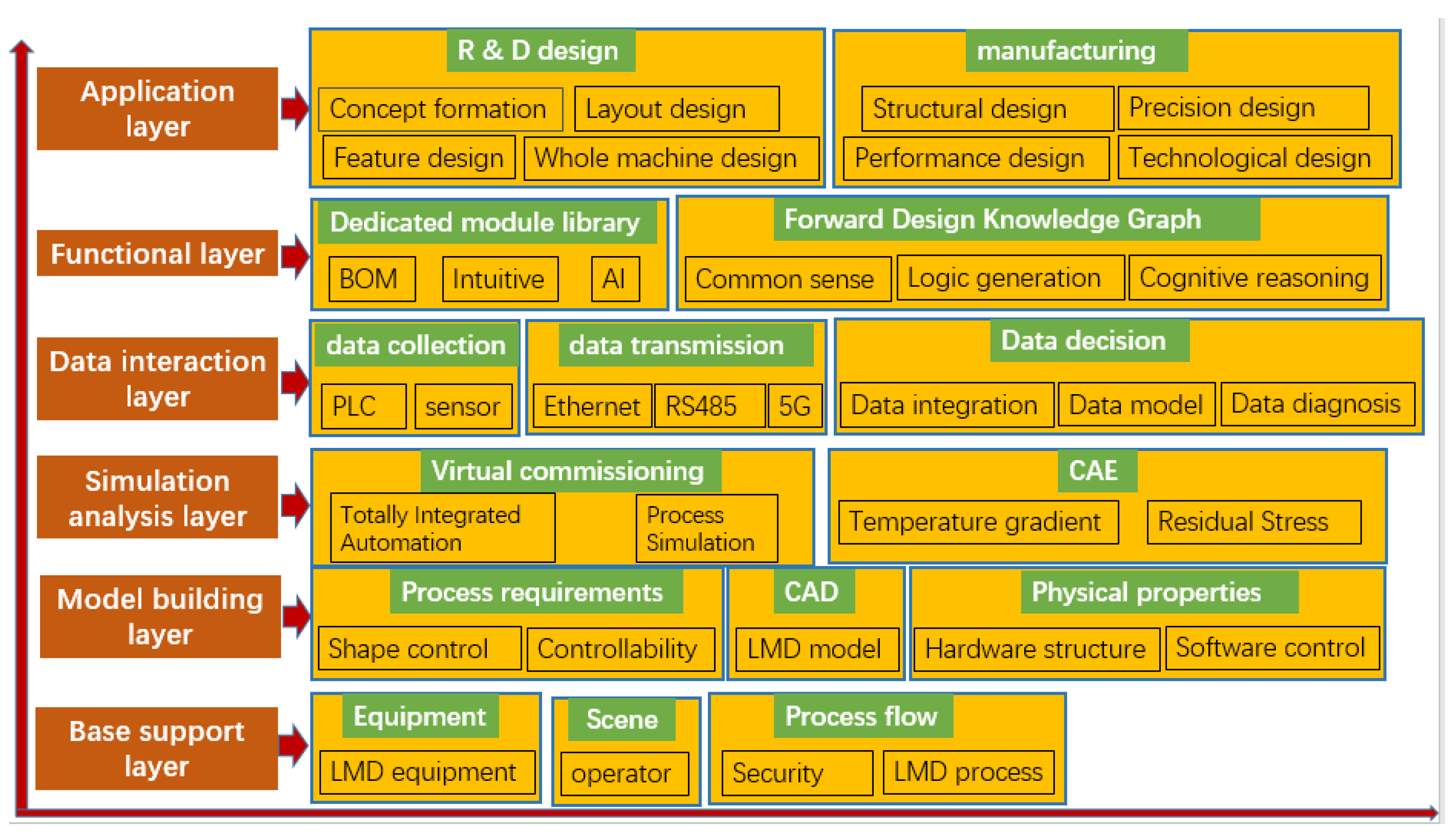
2. Structure Frame of LMD Equipment Based on Digital Twin

Digital twins have the characteristics of intersecting multiple disciplines, personalized customization, and combining virtual and real [30]. As shown in Figure 1, the digital twin model framework is expanded from six dimensions: application layer, functional layer, data interaction layer, simulation analysis layer, model construction layer, and basic support layer. Among them, the application layer originates from the R & D of R & M, and involves research and analysis of the concept formation, function design, overall design, layout design, structure design, precision design, performance design, and process design of the digital twin. Mass data will be generated at different stages. Professional module libraries and integral design knowledge maps in the functional layer are used as support. The data interaction layer is also required to collect, transmit and decide the data generated by R & D of R & M in the application layer, which requires simulation. The analysis layer and model building layer involve: the geometric information acquisition, controllability, and shape control process requirements of LMD equipment, hardware structure and physical properties of software control, component assembly, and PLC debugging, temperature gradient, and residual stress in the processing process, etc. In addition to the simulation analysis process of product structure characteristics, it is also necessary to consider the actual LMD equipment processing environment. On-site operators and equipment can produce safely and efficiently, forming a LMD process flow, and integrating real-time sensor data information for optimization and decision-making.
The main structure of LMD equipment is integrated by five major parts, namely the equipment platform structure, print head structure, powder feeding structure laser structure, and cooling structure, as shown in Figure 2. The structure of the equipment platform is mainly formed by the X, Y, Z axis lead screws and the motor (X, Y, Z guide rail strokes are 700 mm, 200 mm, and 200 mm, respectively), the working platform (1100 mm × 1200 mm), and two additional rotating shafts. It is five-axis linkage equipment. The print head structure includes coaxial powder feeding nozzles and laser print heads. The powder feeding structure includes a single-tube carrier gas powder feeder. The laser structure is mainly a 1000 W semiconductor laser. The cooling structure comprises a water chiller. It cools the laser head to prevent the temperature of the laser head from becoming too high, and the powder melting inside the powder feeding pipe, which causes the powder feeding pipe to become blocked and the LMD cannot be performed normally.
The process requirements of LMD equipment are mainly to achieve shape control and controllability in the LMD process. In the actual LMD process, the main reasons for the uneven temperature field distribution and stress concentration of the entire part are the continuous deposition of local features, the deposition of different wall thicknesses, and the heat dissipation [31,32]. In order to achieve control of internal stress and the diagnosis and suppression of defects in the LMD process, simulation technology is used to predict the changing law of the temperature field in the LMD forming process, and then the laser energy, scanning speed, powder feeding speed, and other process parameters are adjusted. This minimizes or even eliminates the cracks caused by the continuous local heating of the LMD [33,34]. Nassar et al. [35] used temperature feedback as a closed-loop control of the LMD process within the layer, to ensure that the ambient temperature of the starting point was lower than the threshold temperature before LMD, thereby making the microhardness more uniform. Farshidianfar [36] et al. developed an infrared imaging system to detect changes in the surface temperature of LMD, and real-time control of the closed-loop method of microstructure deposition. It uses the correlation between the cooling speed, travel speed, and the microstructure of the LMD layer, and establishes a PID controller (proportional-integral-derivative controller) to control the cooling speed, thereby improving the microstructure performance of the LMD layer. In order to achieve real-time control of the temperature field of the molten pool, an additional infrared thermal imager is used to collect the surface temperature field pixels of the LMD molten pool, and directly extract the temperature data in the temperature field pixels, through professional software. The mapping clustering algorithm is organized for training. After the training is successful, the proportional integral derivative and feedforward compensation are combined to form a closed-loop control.
The LMD equipment model based on digital twins has virtual and real consistency, can fully integrate, collect data in real time, interact with data, diagnose and analyze data, and make optimization decisions. It cannot only debug directly in the virtual layer, but also does not need to wait until the physical layer is built to complete the debugging, thus providing systematic design information for the R & D of LMD equipment, and reducing the cycle and cost from R & D to application production. It can also achieve the purpose of virtual control, which requires receiving information from the physical layer through the sensor system, and transmitting the information to the virtual layer in real-time; providing diagnosis and analysis through machine learning, and real-time feedback control of the processing activity of the LMD equipment. This ensures that the stability of the LMD equipment processing activity is conducive to solving the complex non-equilibrium physical, metallurgical, and thermal physics changes in the LMD process, thus controlling the distribution of thermal stress, preventing deformation and cracking, and improving the LMD layer internal quality and related mechanical properties, and other characteristics. It can be found that the physical information system can play a role in supporting the dynamic connection between the physical entity and the virtual entity model, forming the characteristics of virtual control of the real, and the fusion of virtual and real.

3. LMD Equipment Model Based on Digital Twin

3.1. Virtual Assembly

Figure 3 is a schematic diagram of the virtual assembly of the LMD equipment model. The virtual assembly of LMD equipment mainly involves the assembly of the geometric model of LMD equipment. The 3D model generated by Solidworks is converted into its format through CrossManager software and imported into Siemens’ Tecnomatix PS (Tecnomatix Process Simulate) software. The sequence editor and path editor in Tecnomatix PS are used for virtual assembly of the equipment platform structure. After the assembly is completed, the print head is installed on the equipment platform structure. On the above model, the assembly of the print head on the equipment platform structure is realized, the assembly method is similar, and the effect of assembly animation is finally presented, which is beneficial to guide the assembly personnel to install more efficiently.

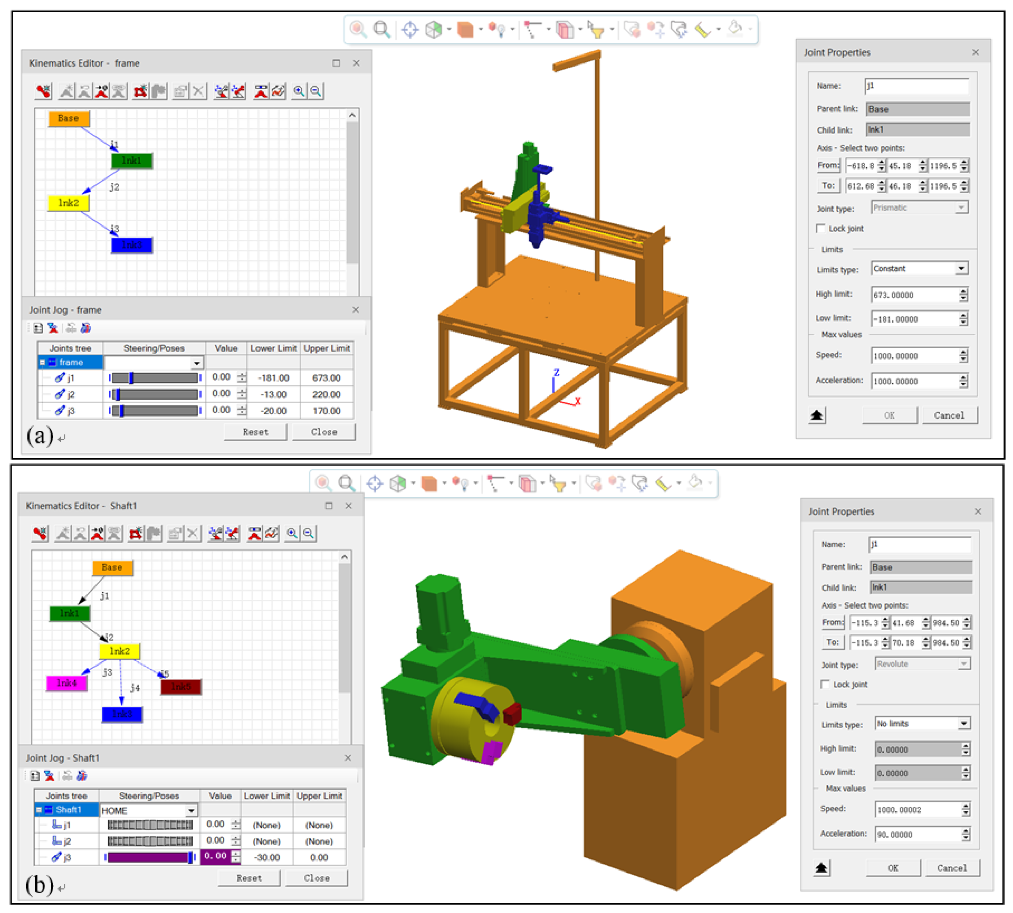
3.2. Sports Settings

Figure 4 is a schematic diagram of the movement setting of the LMD equipment model. The movement setting of the equipment platform structure and the print head structure of the LMD equipment model is carried out. Firstly, the various components of the equipment platform and the print head are selected. The direction and speed of movement of the selected components are then set. From the left half of Figure 4a,b, it can be seen that the blue arrows are connected in turn, according to the transmission of the components, while the right half of Figure 4a,b, shows the component transmission setting. This part mainly includes the settings of the sequence, form, direction, speed, and acceleration of the equipment platform structure in X, Y, Z, and rotary axis components. The movement setting is conducive to the full integration of the physical conditions of each part of the LMD equipment model with the actual structure, thereby ensuring the success of the consistency of virtual and real.

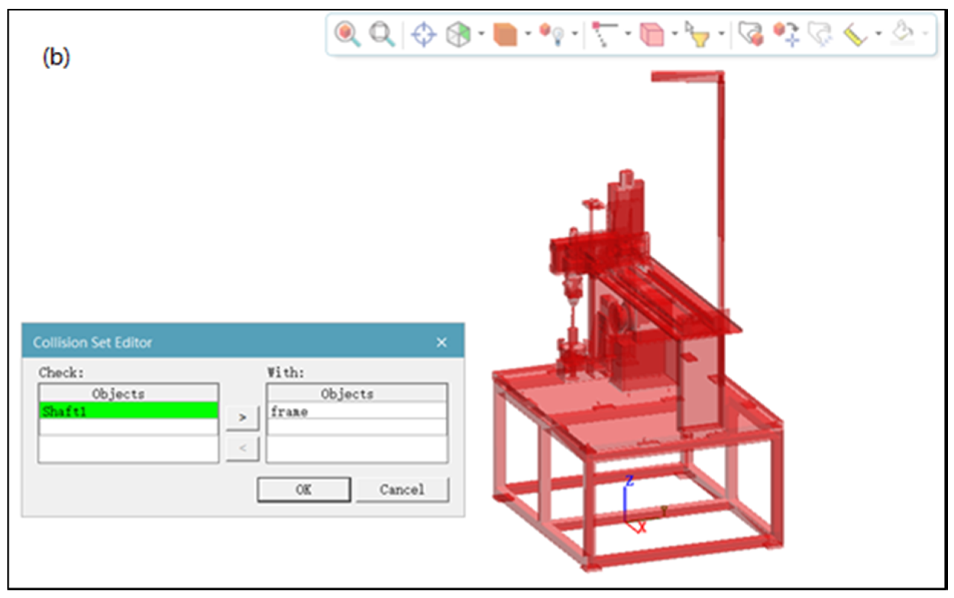
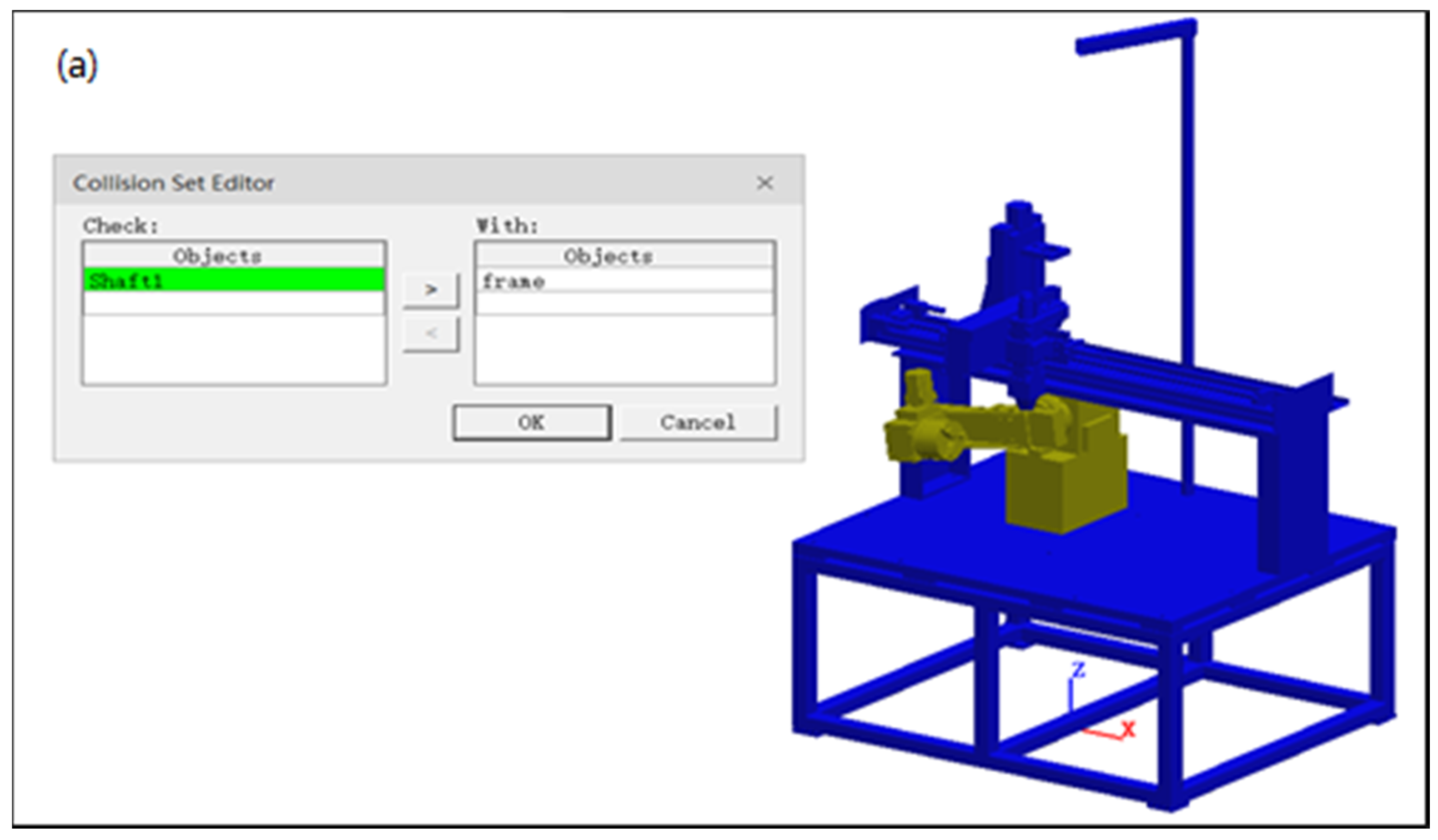
3.3. Collision Inspection
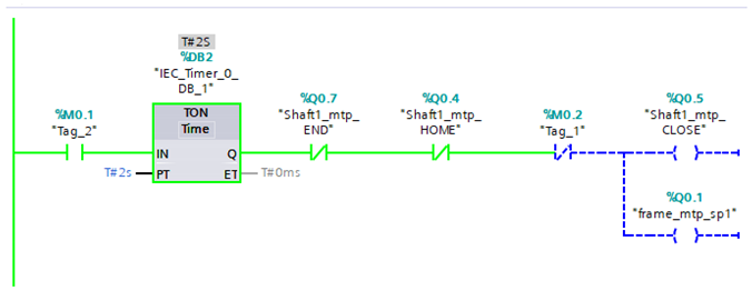
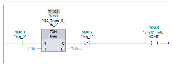
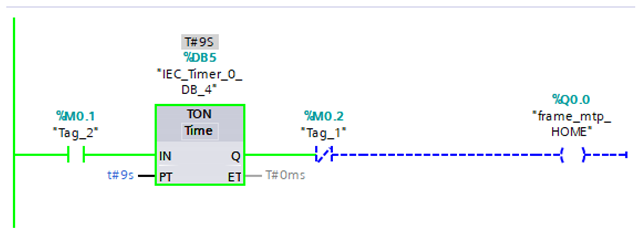
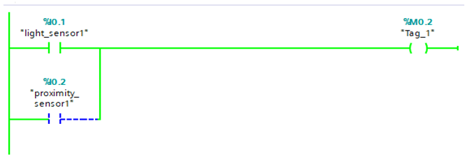
Figure 5 is a flow chart of collision inspection work. The movement of the LMD equipment model structure and the trajectory of the strengthened part surface are set for collision inspection, so that the LMD equipment model structure can detect the parts. After the setting is completed, collision inspection is required to be opened for testing. Otherwise, during PLC debugging, no warning sound will be issued for the collision between the digital twin structure of the LMD equipment and the movement of the print head, and the red indicator will be displayed for the overall collision structure. The collision detection between the remanufactured and printed working parts, and the digital twin structure of the LMD equipment, is beneficial to planning the processing trajectory and avoiding collisions caused by the processing trajectory. Figure 6 is a schematic diagram of the collision inspection of the LMD equipment model; Figure 6a shows that no collision has been detected, and Figure 6b shows that a collision has been detected and an alarm activated.

3.4. PLC Debugging

The core of the PLC debugging of the LMD equipment model is the OPC (OLE for Process Control) technology. In order to debug the LMD equipment in advance, the production cell can verify and analyze the parameters in the design stage, connecting with PLC through OPC DA (Data Access). In addition, the logic block for PLC debugging is equivalent to the logic block in CEE (Cyclic Event Evaluation) simulation. These two types of simulation can be combined arbitrarily. This study uses a virtual PLC to connect. After running the PLC, it can control the normal operation and processing of the equipment, and there will be no equipment collision and injury. It is only necessary to connect with real PLC, to further realize production automation through PLC programming.
The digital twin motion logic signal of the LMD equipment is loaded into the simulation panel, and then, through the connected virtual PLC, PLC programming can be used to realize the setting of the digital twin motion logic signal of the LMD equipment, as shown in Figure 7.
In order to avoid safety accidents with LMD equipment, it is necessary to conduct a virtual check of the safety early warning of LMD equipment. Through the analysis of the equipment operating status, the data collected by the sensors are extracted for information processing, and judgment and identification, and finally the diagnosis decision is made. The dynamic response process of the safety early warning virtual check control of the analysis and monitoring cycle includes three main aspects: (1) During the operation of the LMD equipment, because of the possibility of manual operation errors, the equipment operation will exceed the equipment mechanical stroke. In order to ensure that there will be no accidents during the operation of the LMD equipment, it is necessary to install and arrange the displacement sensor of the LMD equipment through Siemens’ Tecnomatix PS software, and generate corresponding sensor signals; (2) In order to ensure that there will be no machine injury accidents, when people enter the operating range of the LMD equipment at less than a safe distance, it is necessary to further restrict the safe movement range for people, by installing a proximity displacement sensor; (3)PLC motion programming of the digital twin of LMD equipment is carried out through Siemens’ TIA Portal V15.1 software. The specific PLC programming is shown in Appendix A.

4. Conclusions

Digital twin is a complex product simulation model that integrates multi-physics, multi-scale, and probability. It can reflect the status of real products in real time. It is a key way to realize the integration of product R & M information and physical. Under the concept of digital twins, this paper explores the system framework and modeling of LMD equipment based on digital twins. After explaining the development process of digital twins, the application progress of digital twins is summarized.
On this basis, this research proposes an LMD equipment model framework based on digital twins, including geometric information acquisition, process requirements, physical properties, component assembly, and PLC debugging. It constructs an LMD equipment model, and performs virtual assembly, motion settings, collision inspection and PLC debugging. This article provides a new perspective and insights for improving the R & D efficiency of LMD equipment. It is hoped that the research work in this article will assist the further application of digital twin technology in IM in the future.

Author Contributions

Conceptualization, C.C.; C.W.; methodology, A.F.; C.C.; C.W.; investigation, A.F.; C.C.; data curation, Y.W. (Yacheng Wei); Y.W. (Yu Wang); writing—original draft preparation, A.F.; C.C.; writing—review and editing, A.F.; C.C.; C.W. All authors have read and agreed to the published version of the manuscript.

Funding

This research was funded by the Wenzhou Science and Technology Bureau Major Science and Technology Special Project, grant number 2018ZG018, Zhejiang Provincial Natural Science Foundation of China, grant number LY20E050027 and the Zhejiang University Student Science and Technology Innovation Activity Plan, grant number 2019R429051.

Institutional Review Board Statement

Not applicable.

Informed Consent Statement

Not applicable.

Data Availability Statement

Not applicable.

Conflicts of Interest

The authors declare no conflict of interest. The funders had no role in the design of the study; in the collection, analyses, or interpretation of data; in the writing of the manuscript, or in the decision to publish the results.

Appendix A. PLC Programming for Virtual Check of Safety Warning

Program segment 1:
Metals 12 00169 i001
Program segment 2:
Metals 12 00169 i002
Program segment 3:
Metals 12 00169 i003
Program segment 4:
Metals 12 00169 i004
Program segment 5:
Metals 12 00169 i005
Program segment 6:
Metals 12 00169 i006
Program segment 7:
Metals 12 00169 i007

References

  1. Tao, F.; Zhang, L.; Lu, K.; Zhao, D. Research on manufacturing grid resource service optimal-selection and composition framework. Enterp. Inf. Syst. 2012, 6, 237–264. [Google Scholar] [CrossRef]
  2. Tao, F.; Feng, Y.; Zhang, L.; Liao, T.W. CLPS-GA: A case library and Pareto solution-based hybrid genetic algorithm for en-ergy-aware cloud service scheduling. Appl. Soft Comput. 2014, 19, 264–279. [Google Scholar] [CrossRef]
  3. Tao, F.; Zhang, M. Digital Twin Shop-Floor: A New Shop-Floor Paradigm towards Smart Manufacturing. IEEE Access 2017, 5, 20418–20427. [Google Scholar] [CrossRef]
  4. Grieves, M. Virtually Perfect: Driving Innovate and Lean Products through Product Levycle Management; NCMS: Ann Arobr, MI, USA, 2011. [Google Scholar]
  5. Tao, F.; Sui, F.; Liu, A.; Qi, Q.; Zhang, M.; Song, B.; Guo, Z.; Lu, S.C.-Y.; Nee, A.Y.C. Digital twin-driven product design framework. Int. J. Prod. Res. 2019, 57, 3935–3953. [Google Scholar] [CrossRef] [Green Version]
  6. Tao, F.; Cheng, J.; Qi, Q.; Zhang, M.; Zhang, H.; Sui, F. Digital twin-driven product design, manufacturing and service with big data. Int. J. Adv. Manuf. Technol. 2018, 94, 3563–3576. [Google Scholar] [CrossRef]
  7. Singh, V.; Willcox, K.E. Engineering Design with Digital Thread. AIAA J. 2018, 56, 4515–4528. [Google Scholar] [CrossRef]
  8. Helu, M.; Joseph, A.; Hedberg, T. A standards-based approach for linking as-planned to as-fabricated product data. CIRP Ann. 2018, 67, 487–490. [Google Scholar] [CrossRef] [PubMed]
  9. Rosen, R.; Heinzerling, T.; Schmidt, P. The role of simulation in the context of digital twins Virtual commissioning models as mediator between phases and applications. ATP Mag. 2021, 4, 82–89. [Google Scholar] [CrossRef]
  10. Stavropoulos, P.; Papacharalampopoulos, A.; Athanasopoulou, L. A molecular dynamics based digital twin for ultrafast laser material removal processes. Int. J. Adv. Manuf. Technol. 2020, 108, 413–426. [Google Scholar] [CrossRef]
  11. Haberland, C.; Elahinia, M.; Walker, J.M.; Meier, H.; Frenzel, J. On the development of high quality NiTi shape memory and pseudoelastic parts by additive manufacturing. Smart Mater. Struct. 2014, 23, 2. [Google Scholar] [CrossRef]
  12. Breuninger, J. Additive manufacturing: Challenges and advantages for the medical industry. Puerto Rico Health Sci. J. 2000, 19, 57. [Google Scholar]
  13. Xu, W.; Lui, E.; Pateras, A.; Qian, M.; Brandt, M. In situ tailoring microstructure in additively manufactured Ti-6Al-4V for superior mechanical performance. Acta Mater. 2017, 125, 390–400. [Google Scholar] [CrossRef]
  14. Abdel-latif, M.; Abdel-Ghany, K.; El-Mahallawy, N. Effect of Laser Speed on Microstructure and Mechanical Properties of AISI H13 Tool Steel Prepared by Laser Powder Bed Fusion Process. J. Mater. Eng. Perform. 2021, 30, 8821–8830. [Google Scholar] [CrossRef]
  15. Yu, L.; Chen, K.; Zhang, Y.L.; Liu, J.; Yang, L.; Shi, Y. Microstructures and mechanical properties of NiTi shape memory alloys fabricated by wire arc additive manufacturing. J. Alloys Compd. 2022, 892, 162193. [Google Scholar] [CrossRef]
  16. Tang, L.; Landers, R.G. Melt Pool Temperature Control for Laser Metal Deposition Processes-Part I: Online Temper-ature Control. J. Manuf. Sci. Eng. 2010, 132, 1. [Google Scholar] [CrossRef]
  17. Cui, X.; Zhang, S.; Zhang, C.; Chen, J.; Zhang, J.; Dong, S. A comparison on microstructure features of 24CrNiMo low alloy steel prepared by selective laser melting and laser melting deposition. Vacuum 2021, 191, 110394. [Google Scholar] [CrossRef]
  18. Chekotu, J.C.; Groarke, R.; O’Toole, K.; Brabazon, D. Advances in Selective Laser Melting of Nitinol Shape Memory Alloy Part Production. Materials 2019, 12, 809. [Google Scholar] [CrossRef] [Green Version]
  19. Wang, X.; Kustov, S.; Van Humbeeck, J. A Short Review on the Microstructure, Transformation Behavior and Functional Properties of NiTi Shape Memory Alloys Fabricated by Selective Laser Melting. Materials 2018, 11, 1683. [Google Scholar] [CrossRef] [Green Version]
  20. Gu, D.; Meiners, W.; Wissenbach, K.; Poprawe, R. Laser additive manufacturing of metallic components: Materials, processes and mechanisms. Int. Mater. Rev. 2012, 57, 133–164. [Google Scholar] [CrossRef]
  21. Wang, T.; Zhu, Y.Y.; Zhang, S.Q.; Tang, H.B.; Wang, H.M. Grain morphology evolution behavior of titanium alloy com-ponents during laser melting deposition additive manufacturing. J. Alloys Compd. 2015, 623, 505–513. [Google Scholar] [CrossRef]
  22. Chen, X.; Liu, K.; Guo, W.; Gangil, N.; Siddiquee, A.N.; Konovalov, S. The fabrication of NiTi shape memory alloy by selec-tive laser melting: A review. Rapid Prototyp. J. 2019, 25, 1421–1432. [Google Scholar] [CrossRef]
  23. Huang, Y.; Leu, M.C.; Mazumder, J.; Donmez, A. Additive Manufacturing: Current State, Future Potential, Gaps and Needs, and Recommendations. J. Manuf. Sci. Eng. 2015, 137, 014001. [Google Scholar] [CrossRef] [Green Version]
  24. Wagener, R.; Scurria, M.; Bein, T. About a Digital Twin for the Fatigue Approach of Additively Manufactured Components. In Proceedings of the 11th International Conference on Porous Metals and Metallic Foams (MetFoam 2019); Springer: Berlin/Heidelberg, Germany, 2019; pp. 371–382. [Google Scholar]
  25. DebRoy, T.; Zhang, W.; Turner, J.; Babu, S.S. Building digital twins of 3D printing machines. Scr. Mater. 2017, 135, 119–124. [Google Scholar] [CrossRef]
  26. Bhatt, P.M.; Kulkarni, A.; Malhan, R.K.; Shah, B.C.; Yoon, Y.J.; Gupta, S.K. Automated Planning for Robotic Multi-Resolution Additive Manufacturing. J. Comput. Inf. Sci. Eng. 2022, 22, 1–18. [Google Scholar] [CrossRef]
  27. Liu, J.; Li, G.; Sun, Q.; Li, H.; Sun, J.; Wang, X. Understanding the effect of scanning strategies on the microstructure and crystallographic texture of Ti-6Al-4V alloy manufactured by laser powder bed fusion. J. Mater. Process. Technol. 2021, 299, 117366. [Google Scholar] [CrossRef]
  28. Knapp, G.L.; Mukherjee, T.; Zuback, J.S.; Wei, H.L.; Palmer, T.A.; De, A.; DebRoy, T. Building blocks for a digital twin of additive manufacturing. Acta Mater. 2017, 135, 390–399. [Google Scholar] [CrossRef]
  29. Klingaa, C.; Mohanty, S.; Funch, C.; Hjermitslev, A.; Haahr-Lillevang, L.; Hattel, J. Towards a digital twin of laser powder bed fusion with a focus on gas flow variables. J. Manuf. Process. 2021, 65, 312–327. [Google Scholar] [CrossRef]
  30. Stavropoulos, P.; Papacharalampopoulos, A.; Michail, C.K.; Chryssolouris, G. Robust Additive Manufacturing Performance through a Control Oriented Digital Twin. Metals 2021, 11, 708. [Google Scholar] [CrossRef]
  31. Wang, H.; Hu, Y.; Ning, F.; Cong, W. Ultrasonic vibration-assisted laser engineered net shaping of Inconel 718 parts: Effects of ultrasonic frequency on microstructural and mechanical properties. J. Mater. Process. Technol. 2020, 276, 116395. [Google Scholar] [CrossRef]
  32. Khamidullin, B.; Tsivilskiy, I.; Gorunov, A.; Gilmutdinov, A. Modeling of the effect of powder parameters on laser cladding using coaxial nozzle. Surf. Coat. Technol. 2019, 364, 430–443. [Google Scholar] [CrossRef]
  33. Zhang, Z.; Kovacevic, R. A thermo-mechanical model for simulating the temperature and stress distribution during laser cladding process. Int. J. Adv. Manuf. Technol. 2019, 102, 457–472. [Google Scholar] [CrossRef]
  34. DebRoy, T.; Wei, H.L.; Zuback, J.S.; Mukherjee, T.; Elmer, J.W.; Milewski, J.O.; Beese, A.M.; Wilson-Heid, A.; De, A.; Zhang, W. Additive manufacturing of metallic components–Process, structure and properties. Prog. Mater. Sci. 2018, 92, 112–224. [Google Scholar] [CrossRef]
  35. Nassar, A.R.; Keist, J.; Reutzel, E.; Spurgeon, T.J. Intra-layer closed-loop control of build plan during directed energy additive manufacturing of Ti–6Al–4V. Addit. Manuf. 2015, 6, 39–52. [Google Scholar] [CrossRef]
  36. Farshidianfar, M.H.; Khajepour, A.; Gerlich, A.P. Real-time control of microstructure in laser additive manufacturing. Int. J. Adv. Manuf. Technol. 2016, 82, 1173–1186. [Google Scholar] [CrossRef]
Figure 1. Digital twin system framework of LMD equipment.
Metals 12 00169 g001
Figure 2. Schematic diagram of LMD.
Metals 12 00169 g002
Figure 3. Virtual assembly of LMD equipment model.
Metals 12 00169 g003
Figure 4. Movement setting of LMD equipment model: (a) Three-axis component movement setting, and (b) Rotary axis component movement setting.
Metals 12 00169 g004
Figure 5. Flow chart of collision inspection.
Metals 12 00169 g005
Figure 6. Collision inspection of LMD equipment model: (a) no detection of collision; (b) detection of collision and alarm.
Metals 12 00169 g006aMetals 12 00169 g006b
Figure 7. PLC debugging of LMD equipment model: (a) debugging of LMD equipment model connected to CEE simulation, and (b) debugging of LMD equipment model connecting to virtual PLC.
Metals 12 00169 g007aMetals 12 00169 g007b
Publisher’s Note: MDPI stays neutral with regard to jurisdictional claims in published maps and institutional affiliations.

