
Experimental Study on Titanium Coating Carbide Drill Cutting Nickel-Base Superalloy

Abstract
:1. Introduction
2. Materials and Methods
- (1)
- Workpiece material
- (2)
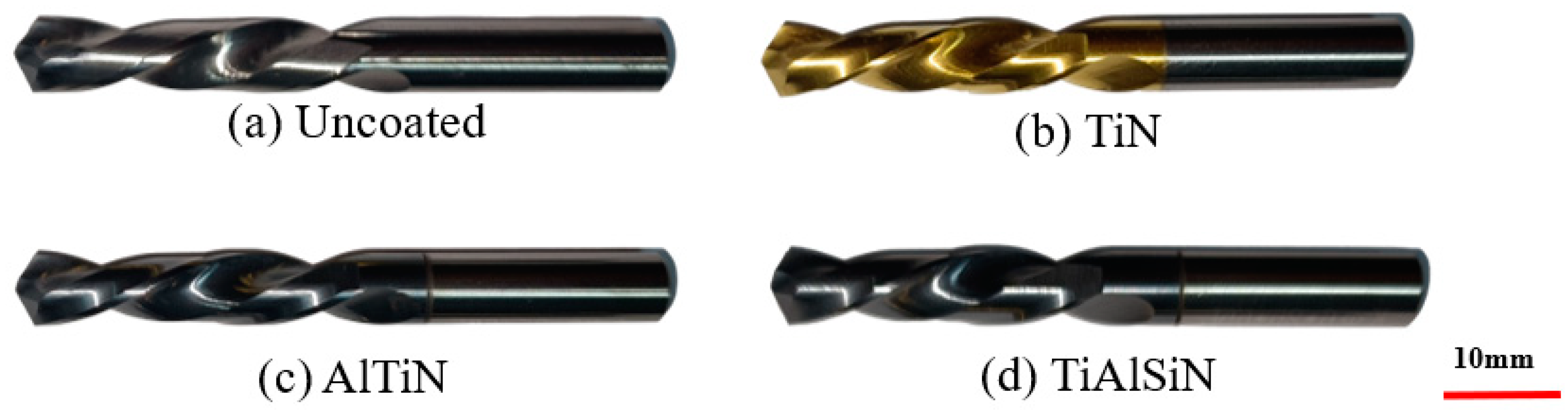
- Drill
- (3)
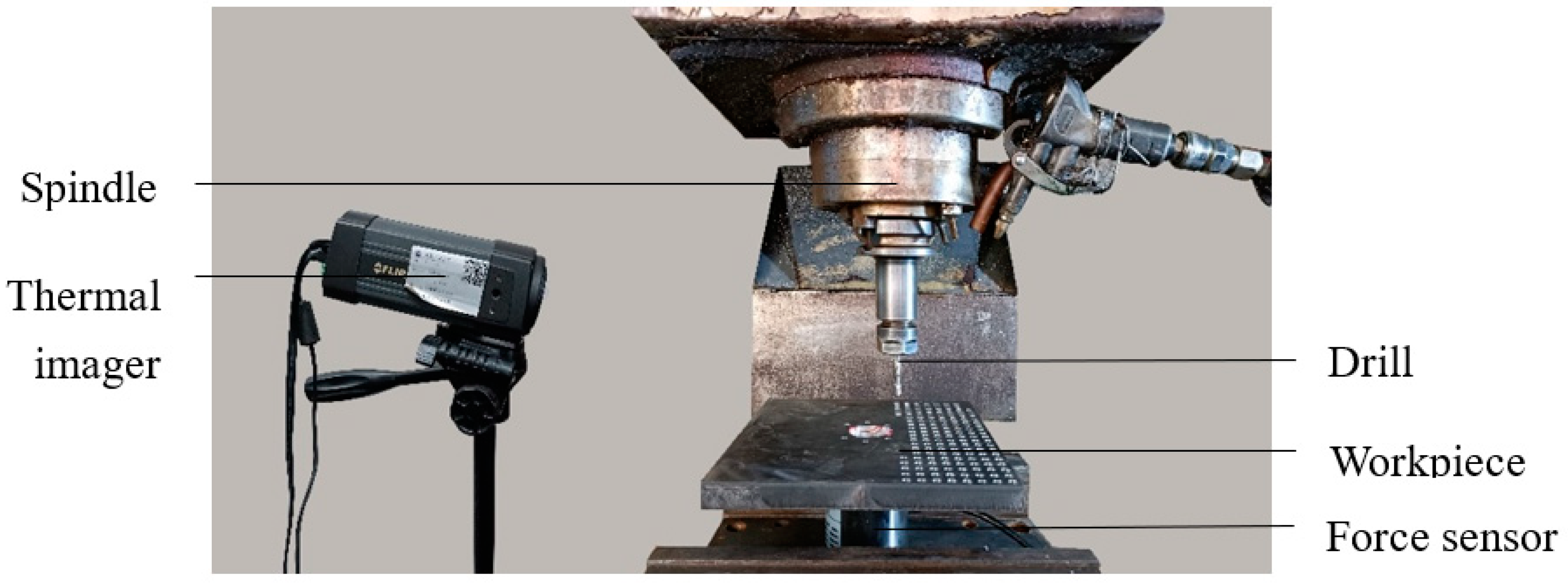
- Test condition
3. Test Results and Analysis
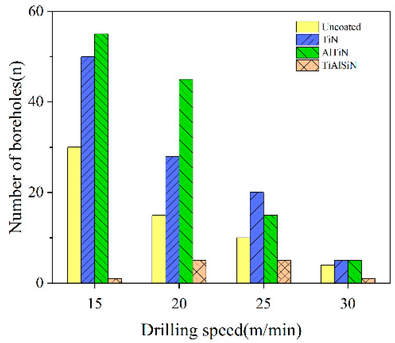
3.1. Drill Life
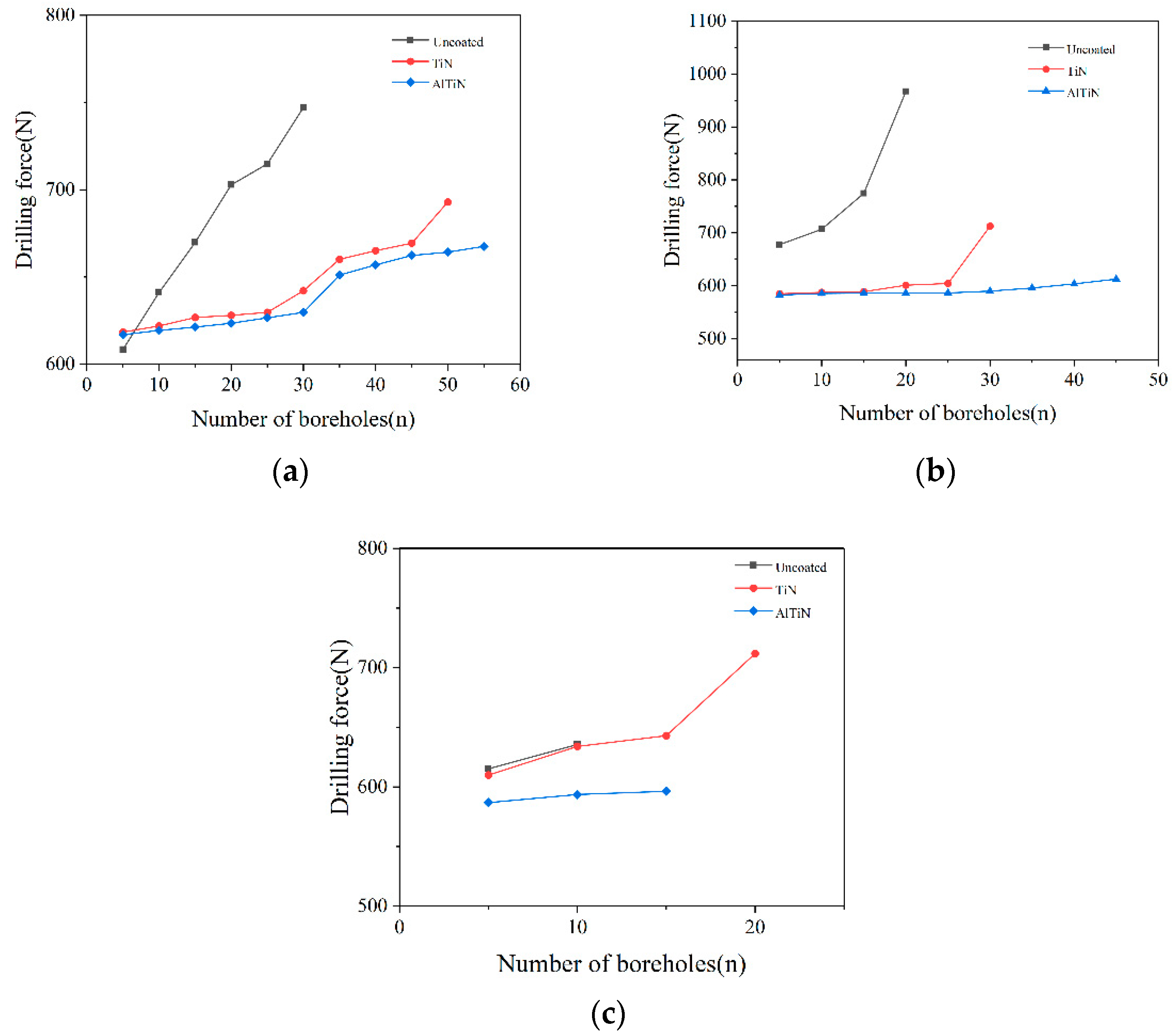
3.2. Drilling Force
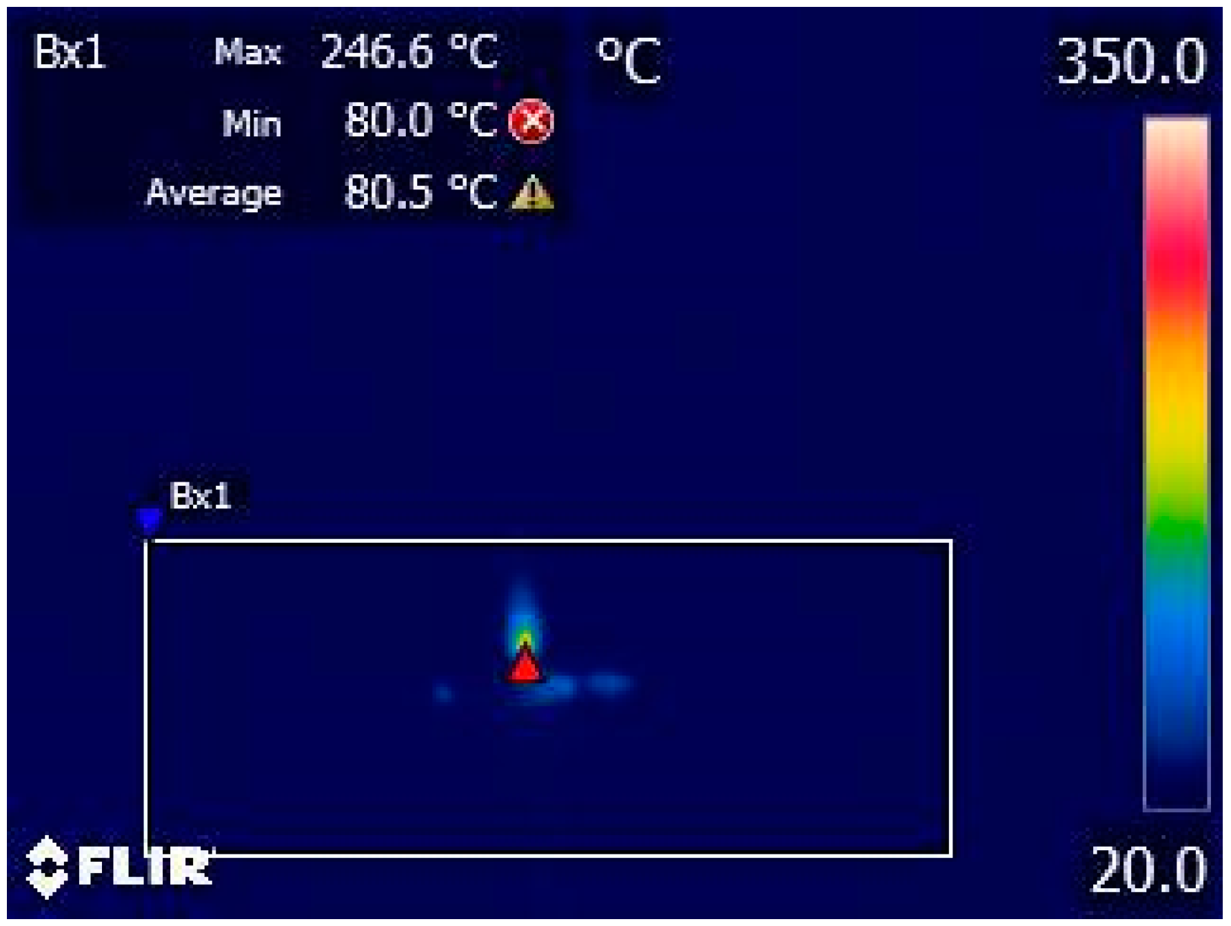
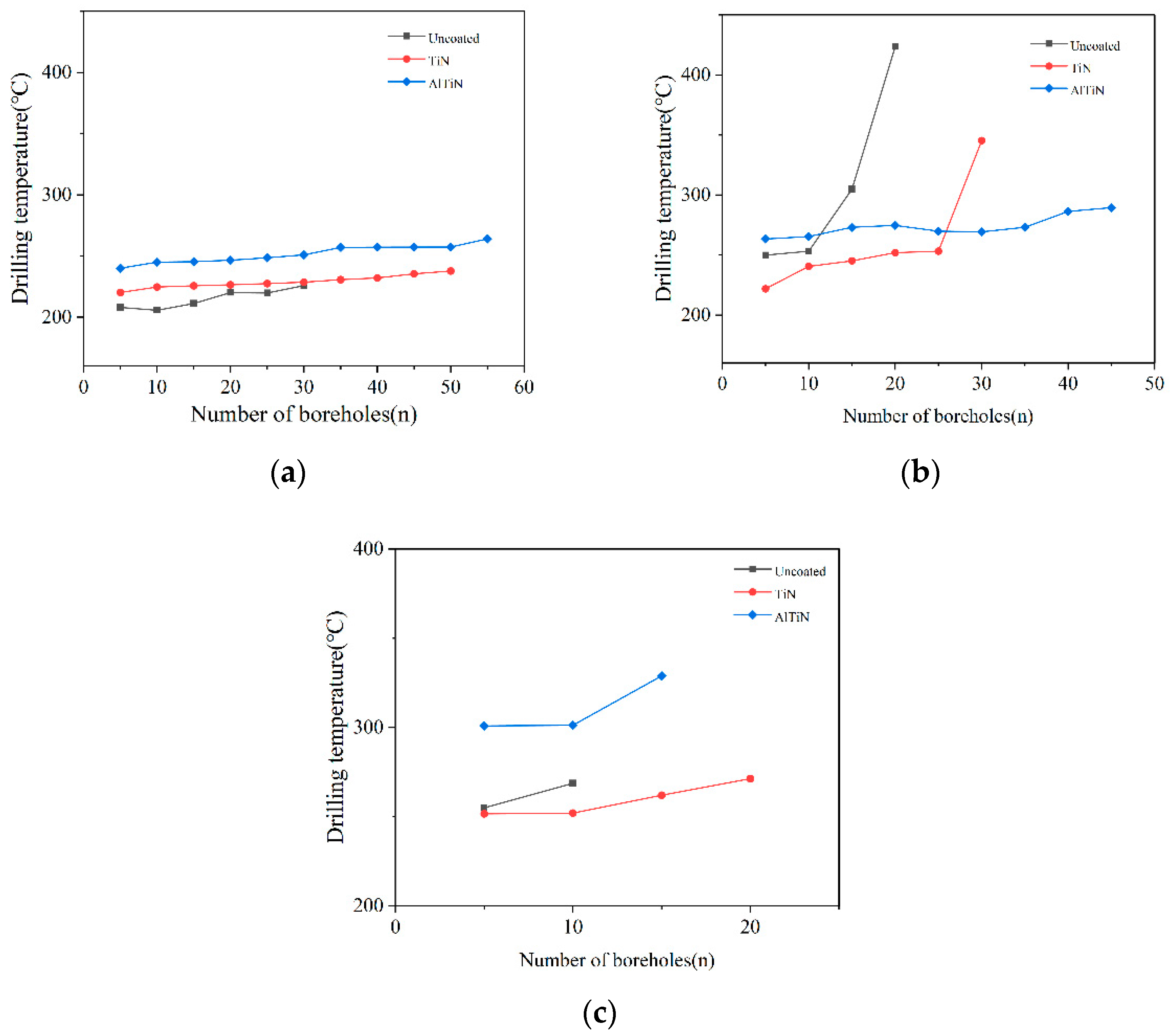
3.3. Drilling Temperature
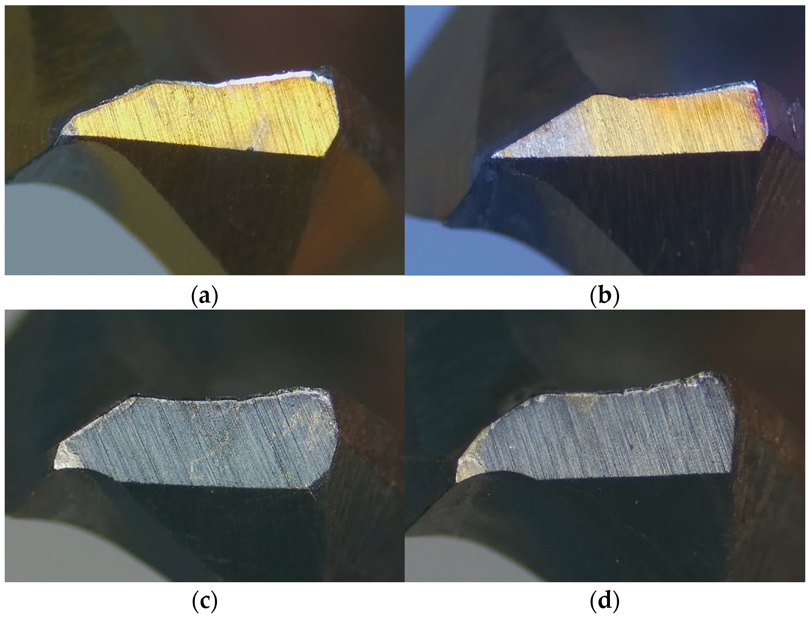
3.4. The Wear Mechanism of Coated Drill
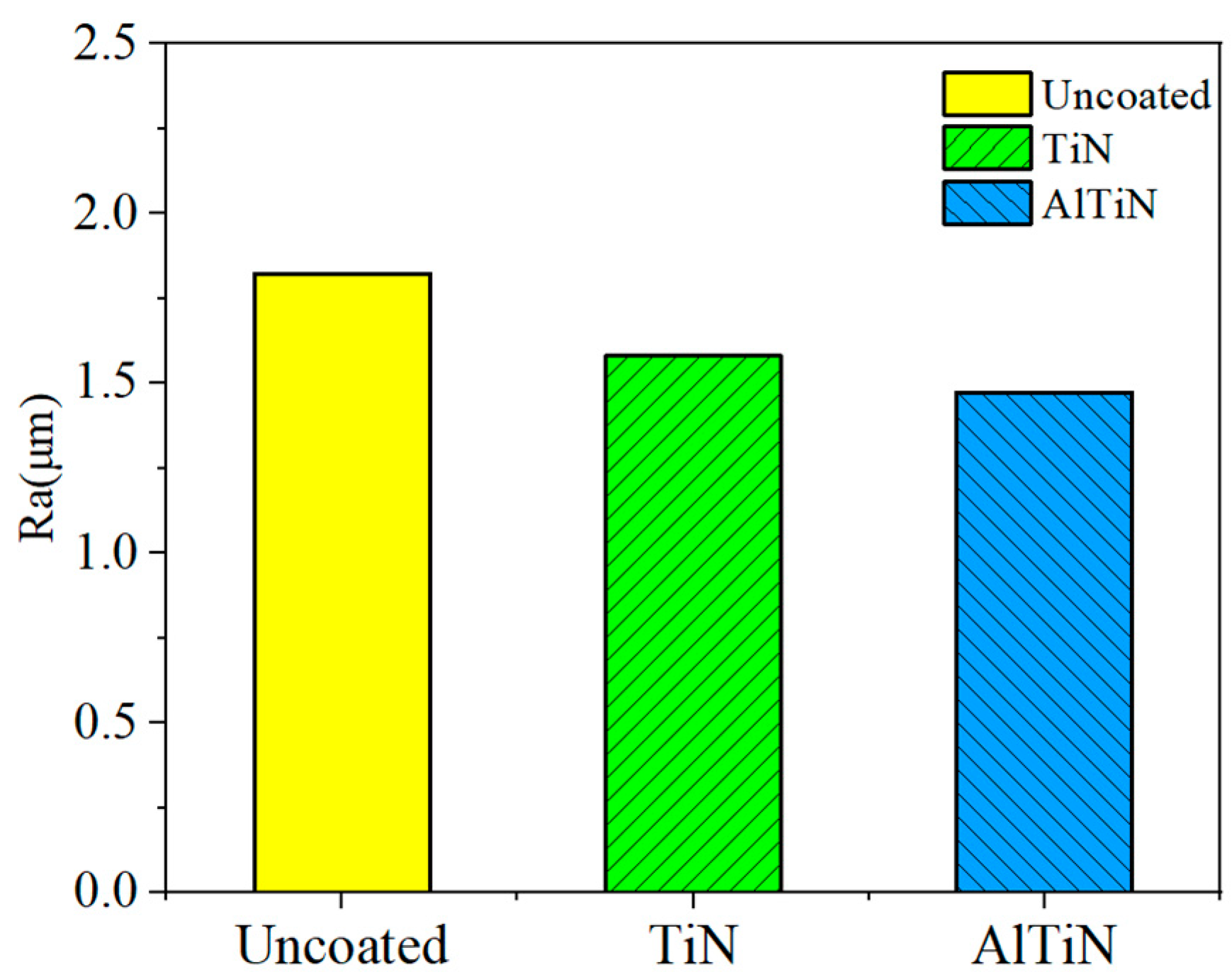
3.5. Roughness of Workpiece Machined Surface
4. Conclusions
- (1)
- TiN coating and AlTiN coating can prolong the tool life of the carbide drill YG10 when drilling nickel-base superalloy GH4169. The TiN coating can prolong tool life by 1.67 times, while the AlTiN coating can prolong tool life by 1.83 times.
- (2)
- The friction force of TiAlSiN coating is small, but the hardness is poor, which leads to it being easily worn. Therefore, it is not suitable for the processing of nickel-base superalloy with high hardness and high strength.
- (3)
- Adhesive wear is the main form of coating drill failure form. As the number of drilling holes of the coated drill increases, the adhesion becomes heavier and the drilling force and temperature increase.
- (4)
- Coating can reduce the roughness of the machined surface of carbide drill drilling nickel-base superalloy and improve the machined quality. The AlTiN-coated drill is slightly better than the TiN coated drill.
Author Contributions
Funding
Institutional Review Board Statement
Informed Consent Statement
Data Availability Statement
Conflicts of Interest
References
- Moreau, E.; Corbin, S. Assessing the influence of Cr and Fe in the filler metal on dissolution and isothermal solidification kinetics during TLPB of Ni-based superalloys. Metall. Mater. Trans. A 2020, 51, 6307–6317. [Google Scholar] [CrossRef]
- Cheng, Y.; Wang, G.; Liu, J.; He, L. Atomic configurations of planar defects in μ phase in Ni-based superalloys. Scr. Mater. 2021, 193, 27–32. [Google Scholar] [CrossRef]
- Gupta, S.; Bronkhorst, C.A. Crystal plasticity model for single crystal Ni-based superalloys: Capturing orientation and temperature dependence of flow stress. Int. J. Plast. 2020, 137, 102896. [Google Scholar] [CrossRef]
- Ezugwu, E.; Bonney, J.; Yamane, Y. An overview of the machinability of aeroengine alloys. J. Mater. Process. Technol. 2003, 134, 233–253. [Google Scholar] [CrossRef]
- Wang, Z.; Liu, B.; Zhao, Z.; Bai, P.; Dong, M.; Zhang, J.; Fan, J.; Ding, T.; Guo, Z. Formability and hardness studies of selective laser melting of GH4169 Ni-based alloy powders. Emerg. Mater. Res. 2020, 9, 758–769. [Google Scholar] [CrossRef]
- Sun, J.L. Research on Chip Formation Mechanism and Cutting Tool Wear in Drilling Superalloy; Shenyang University of Science and Technology: Shenyang, China, 2017. [Google Scholar]
- Eckstein, M.; Vrabel, M.; Mankova, I. Tool Wear and Surface Roughness Evolution in Hole Making Process of Inconel 718. Mater. Sci. Forum 2016, 862, 11–17. [Google Scholar] [CrossRef]
- Kannan, S.; Pervaiz, S.; Vincent, S.; Karthikeyan, R. Tool life and surface integrity aspects when drilling nickel alloy. IOP Conf. Ser. Mater. Sci. Eng. 2018, 346, 012042. [Google Scholar] [CrossRef]
- Li, H.; Gao, F.; Li, Y.; Bai, L. Experimental Study on the Dry Drilling Nickel-Based Superalloy of CrAlYN Coated Carbide Bit. Materials 2022, 15, 4302. [Google Scholar] [CrossRef] [PubMed]
- Jindal, P.C.; Santhanam, A.T.; Schleinkofer, U.; Shuster, A.F. Performance of PVD TiN, TiCN, and TiAlN coated cemented carbide tools in turning. Int. J. Refract. Met. Hard Mater. 1999, 17, 163–170. [Google Scholar] [CrossRef]
- Ucak, N.; Cicek, A. The effects of cutting conditions on cutting temperature and hole quality in drilling of Inconel 718 using solid carbide drills. J. Manuf. Process. 2018, 31, 662–673. [Google Scholar] [CrossRef]
- Umbrello, D. Investigation of surface integrity in dry machining of Inconel 718. Int. J. Adv. Manuf. Technol. 2013, 69, 2183–2190. [Google Scholar] [CrossRef]
- Ren, M. Research on Drilling Characteristics of Superalloy; Shenyang Ligong University: Shenyang, China, 2016; pp. 48–59. (In Chinese) [Google Scholar]
- Ma, S.; Dong, C. Analysis Prediction and optimization of surface residual stress in Micro-milling Superalloy GH4169. Tool Eng. 2018, 52, 79–82. (In Chinese) [Google Scholar]


| Element | Ni | Cr | Nb | Mo | Ti | C | Si | Mn | B | Fe |
|---|---|---|---|---|---|---|---|---|---|---|
| Mass/% | 51.75 | 17 | 5.15 | 2.93 | 1.07 | 0.042 | 0.21 | 0.03 | 0.006 | Bal |
| Density/(kg/m3) | Poisson’s Ratio μ | Thermal Conductivity/(W/m·K) | Specific Heat Capacity/(J/kg·°C) | Modulus of Elasticity/GPa |
|---|---|---|---|---|
| 8240 | 0.3 | 14.7 | 435 | 199.9 |
| Elongation/% | Reduction of section/% | Tensile strength/GPa | Impact Toughness/(MJ/m3) | Yield Strength/MPa |
| 24 | 40 | 1430 | 348 | 1110 |
| Cutting Tool Serial No. | Element Mass Fraction(%) | ||
|---|---|---|---|
| W | Co | C | |
| YG10 | 84 | 10 | 6 |
| Cutting Tool Serial No. | Mechanical Properties | |||||
|---|---|---|---|---|---|---|
| Density g/cm−3 | Hardness HRA | Bending Strength MPa | Compressive Strength MPa | Elastic Modulus GPa | Impact Toughness J/cm−2 | |
| YG10 | 14.7 | 88.5 | 2700 | 4700 | 585 | 2.8 |
| Coating Type | Element Mass Fraction (Wt%) | |||
|---|---|---|---|---|
| Ti | Al | Si | N | |
| TiN | 69.14 | - | - | 30.86 |
| AlTiN | 22.78 | 47.37 | - | 29.86 |
| TiAlSiN | 23.84 | 41.24 | 6.36 | 28.56 |
Publisher’s Note: MDPI stays neutral with regard to jurisdictional claims in published maps and institutional affiliations. |
© 2022 by the authors. Licensee MDPI, Basel, Switzerland. This article is an open access article distributed under the terms and conditions of the Creative Commons Attribution (CC BY) license (https://creativecommons.org/licenses/by/4.0/).
Share and Cite
Li, H.; Gao, F.; Li, Y.; Bai, L. Experimental Study on Titanium Coating Carbide Drill Cutting Nickel-Base Superalloy. Metals 2022, 12, 2136. https://doi.org/10.3390/met12122136
Li H, Gao F, Li Y, Bai L. Experimental Study on Titanium Coating Carbide Drill Cutting Nickel-Base Superalloy. Metals. 2022; 12(12):2136. https://doi.org/10.3390/met12122136
Chicago/Turabian StyleLi, Hui, Feng Gao, Yan Li, and Lijing Bai. 2022. "Experimental Study on Titanium Coating Carbide Drill Cutting Nickel-Base Superalloy" Metals 12, no. 12: 2136. https://doi.org/10.3390/met12122136
APA StyleLi, H., Gao, F., Li, Y., & Bai, L. (2022). Experimental Study on Titanium Coating Carbide Drill Cutting Nickel-Base Superalloy. Metals, 12(12), 2136. https://doi.org/10.3390/met12122136