Article

Innovative Approach for the Evaluation of the Mechanical Behavior of Dissimilar Welded Joints

by
Simone Carone
1,
Pasqualino Corigliano
2,
Gabriella Epasto
2,*,
Vincenzo Moramarco
1,*,
Giulia Palomba
2,
Giovanni Pappalettera
1 and
Caterina Casavola
1
1
Department of Mechanics, Mathematics and Management, Polytechnic University of Bari, Via Orabona n.4, 70125 Bari, Italy
2
Department of Engineering, University of Messina, Contrada Di Dio, 98166 Messina, Italy
*
Authors to whom correspondence should be addressed.
Metals 2022, 12(12), 2039; https://doi.org/10.3390/met12122039
Submission received: 1 November 2022 / Revised: 22 November 2022 / Accepted: 23 November 2022 / Published: 27 November 2022
(This article belongs to the Special Issue Welded and Adhesive Joints for Marine Applications)

Abstract

:
This study aims to propose a thorough experimental methodology to assess the mechanical quality of dissimilar joints. This comprehensive approach investigates the fatigue behavior by exploiting the thermographic method, accompanying and correlating the results with information obtained from extensive measurements of residual stresses and detailed evaluation of fracture surfaces. The integration of the information obtained by this hybrid approach allows for a deeper understanding in terms of fatigue behavior even in complicated situations as those represented by dissimilar welded joints. A complex laser-welded Ti6Al4V/Inconel 625 dissimilar joint, obtained using intermediate inserts of Vanadium and AISI 304, was considered as case study. The residual stresses, both longitudinal and transverse to the weld beads, were measured on surface by means of X-ray diffraction, whereas, for in-depth measurements, the multiple-cut contour method was implemented to determine full 2D maps of longitudinal residual stresses with the first cut, and transverse stresses in the Vanadium insert with the second cut. In the investigation of longitudinal residual stresses, the area mostly affected by harmful tensile residual stresses is the weld between the stainless steel and Vanadium, where the maximum value of about 560 MPa is reached; the analysis of transverse residual stresses highlighted a maximum value of 350 MPa at the core of the Vanadium insert. The fatigue behavior of the joints was investigated along with a detailed analysis of the fractured surfaces by scanning electron and confocal microscopes. The analysis of the fracture surfaces indicated that the failure modes are mainly related to the occurrence of defects on the crack path, especially at stress range higher than 200 MPa, for which a large number of pores cluster were detected. Nevertheless, the crack initiation is usually on the side of Vanadium. When the crack path deviates on the stainless-steel region, the fracture mode is brittle due to high residual stresses.

1. Introduction

One of the extremely interesting research topics, resulting from the continuous and unstoppable industrial progress, is the development of advanced technologies to weld dissimilar materials. Indeed, the development of application-oriented engineering solutions which combine the unique properties of different materials has become increasingly compelling [1]. These solutions arise from the need to enhance design flexibility and product functionality, and respond as well to the demand for cost savings, by minimizing the use of expensive materials. It is straightforward that solutions to join dissimilar materials have become almost indispensable for cutting-edge applications that aim to lighten structures, especially in the automotive, marine and aerospace fields, where they have an impact also on the relevant target of greenhouse gas emissions reduction [2,3,4,5,6]. Therefore, all these factors collectively increase the need to study dissimilar welds. This should not only be performed from a manufacturing point of view, but the evaluation of the mechanical quality of these joints should be considered, as well.
Advanced techniques to join dissimilar metals are constantly developed and optimized [7,8,9,10,11] and among those, laser welding is one of the most widely employed, being a flexible process capable of producing high-quality welds with narrow heat affected zones [1,12]. However, the process of welding dissimilar materials entails several critical issues [1,13]. Due to different physical and chemical properties, a direct junction of the dissimilar materials can lead to the formation of micro-cracks and brittle intermetallic compounds, thereby deteriorating the mechanical properties of the dissimilar joint [14,15,16,17]. On the one hand, a way to address these problems, when adopting fiber laser welding, is to properly tune the processing parameters, selecting a combination of higher laser power, higher welding speed, and focusing the beam with an offset toward one of the two welded materials [5,18]. On the other hand, the above mentioned issues can also be overcome by interposing suitable metallic inserts, thus inhibiting the development of brittle phases [19,20,21,22,23,24]. As a result, dissimilar joints can be particularly complex being made of more than two materials. The inherent complexity of this kind of joint would require a wise integration of different experimental approaches for a deeper comprehension of the mechanical behavior.
However, an up-to-date quality assessment of these joints mostly relies on research focused on evaluating microstructure, hardness, shear strength for lap joints or tensile strength for butt welds [5,12,20,21,22,23], and corrosion [25,26]. Many aspects cannot be fully captured by those analyses, especially when dealing with complex loading states, such as fatigue, which is a crucial condition for numerous applications in the automotive, marine, and aerospace fields, for which specific requirements are included in rules and regulation. As reported in [13,27], the fatigue strength of welded structures is a critical issue due to the formation of brittle intermetallic compounds and micro-cracks during welding [1,5,28]. Furthermore, the dissimilar welding process produces a residual stress field [29]. When welding dissimilar materials, residual stresses develop as a result of thermal cycles and of different Coefficients of Thermal Expansion (CTE) for each material, thereby significantly affecting the mechanical properties of the joint, most notably fatigue life [30,31]. Therefore, a comprehensive assessment of the residual stress state plays a key role in the characterization of dissimilar joints [32].
Nevertheless, most of literature studies investigating the residual stress state of laser-welded dissimilar joints are limited to localized and superficial measurements by X-ray diffraction (XRD) and hole drilling without any attempt to correlate this information with the fatigue behavior of the joint [33,34,35,36]. Furthermore, the majority of the research on fatigue properties of dissimilar welded joints does not analyze residual stresses and their contribution by any means. Conversely, only few studies investigated at the same time fatigue and residual stresses in dissimilar joints [37,38,39,40,41]. Scialpi et al. [37] analyzed the fatigue behavior of an ultra-thin friction stir welded joint consisting of two different aluminum alloys, and performed hole drilling measurements. They found limited compressive residual stresses affecting the dissimilar joint; however, these results were influenced by the low plate thickness. Zhang et al. [38] studied the fatigue life of a dissimilar welded T-joint between SAF2205 and AISI 304. Residual stresses were measured using impact indentation method along a linear path at the weld toe; nevertheless, to obtain more information, the authors had to perform a finite element simulation of the welding process. They found that the effect of residual stresses on fatigue estimation was significant and that residual stresses mainly affected mean stress rather than the stress amplitude. In addition, Ahmad et al. [39] had to perform a finite element analysis for residual stress assessment of a multi-pass welded joint between a Nickel alloy and 12Cr steel, using six surface hole drilling measurements to qualitatively validate numerical results. Therefore, the numerical results were used to investigate the effect of residual stresses on the fatigue stress range by exploiting a modified Goodman equation which takes into account welding residual stresses. Other research works on the fatigue behavior of dissimilar joints have only carried out point and surface measurements by X-ray diffractometry [40,41].
In view of the foregoing, to pursue a comprehensive investigation of the mechanical quality of dissimilar joints, it is necessary to study the fatigue properties and their correlation with residual stresses and defects. To carry out this extensive analysis, the authors propose to integrate information from fatigue characterization accompanied by thermographic analysis techniques, residual stress field assessment using experimental techniques as X-ray diffractometry and contour method, and fractographic and chemical evaluation of fracture surfaces. Therefore, a better understanding of the fracture modes can be obtained from information on the residual stress field, not only at the surface but also at depth, and from the analysis of fracture surfaces. Consequently, these results can be correlated with fatigue results with more confidence and accuracy, especially considering the complexity of dissimilar welds.
The aim of this research is to propose a comprehensive experimental approach to characterize the fatigue behavior of dissimilar joints, taking into account the relationship with residual stresses and fracture modes. A complex 2-mm-thick laser-welded Ti6Al4V/Inconel 625 dissimilar welded joint with intermediate inserts of Vanadium and AISI 304 was considered as case study [42,43]. Titanium alloys combine high strength with good corrosion resistance, while Inconel alloys exhibit superior mechanical properties even at elevated temperatures. This combination of materials would greatly reduce production costs of gas turbine engines, power industry parts, and even for ocean engineering systems (pipelines) [43]. Residual stresses, both longitudinal and transverse to the weld beads, were measured on surface by means of X-ray diffraction, whereas, for in-depth measurements, the multiple-cut contour method was implemented to determine full 2D maps of longitudinal residual stresses with the first cut, and transverse stresses in the Vanadium insert. A detailed analysis of the fractured surfaces was performed. In this way, the fatigue behavior was investigated, highlighting the correlation between fatigue strength, residual stresses, and fracture modes to thoroughly evaluate the mechanical quality of the dissimilar joint. The suggested investigation approach, which combines information from several advanced experimental and numerical analysis, is aimed at providing a reliable and complete methodology to assess the quality and retrieve information on fatigue life of complex dissimilar welded joints. This approach provides more detailed and consistent data in comparison to the great majority of current literature, which are crucial to assess the reliability of similar welded solutions, especially in applications requiring advanced performance and accurate knowledge of the main features of the material.

2. Materials and Methods

The suggested experimental methodology aimed at analyzing the fatigue behavior of dissimilar joints is structured as follows:
  • as a first step, surface residual stresses are measured, both in the longitudinal direction and transverse to the weld seams, through a more precise and possibly nondestructive technique, such as X-ray diffraction;
  • next, measurements are extended to depth by exploiting the contour method, which determines a 2D map of residual stresses acting normal to a plane [44]. This technique is easily applicable and particularly suitable to welded joints, owing to the fact that it is not affected by microstructural changes and inhomogeneities, and it is capable of capturing even steep stress gradients [44,45]. Indeed, it has been successfully employed on dissimilar joints, especially friction-welded [42,46,47,48,49];
  • since the contour method is a destructive technique and capable of measuring only one stress component per each cut, longitudinal stresses, which are generally larger in magnitude, should be measured as first followed by transverse stress;
  • subsequently, fatigue tests have to be performed in conjunction with a thermographic analysis of the increase in surface temperature of the specimens to monitor the failure zone [43];
  • finally, fractographic and chemical assessment of the fracture surfaces has to be carried out;
  • a final integration of all the information will allow for a thorough evaluation of the fatigue behavior of the joint and of the mechanisms and the nature of the observed fracture.

2.1. Materials and Welding Conditions

To manufacture the complex dissimilar joints examined, two inserts of pure Vanadium and AISI 304 were selected to join Ti6Al4V and Inconel 625 to inhibit the formation of TixNiy brittle phases. Additional information on the selection of this particular combination of interlayers can be found in [42,43]. Table 1 reports the nominal chemical compositions of the base metals and Vanadium, as well as the chemical composition of AISI 304 measured by X-ray Fluorescence (XRF). Moreover, the mechanical properties of the investigated alloys are summarized in Table 2.
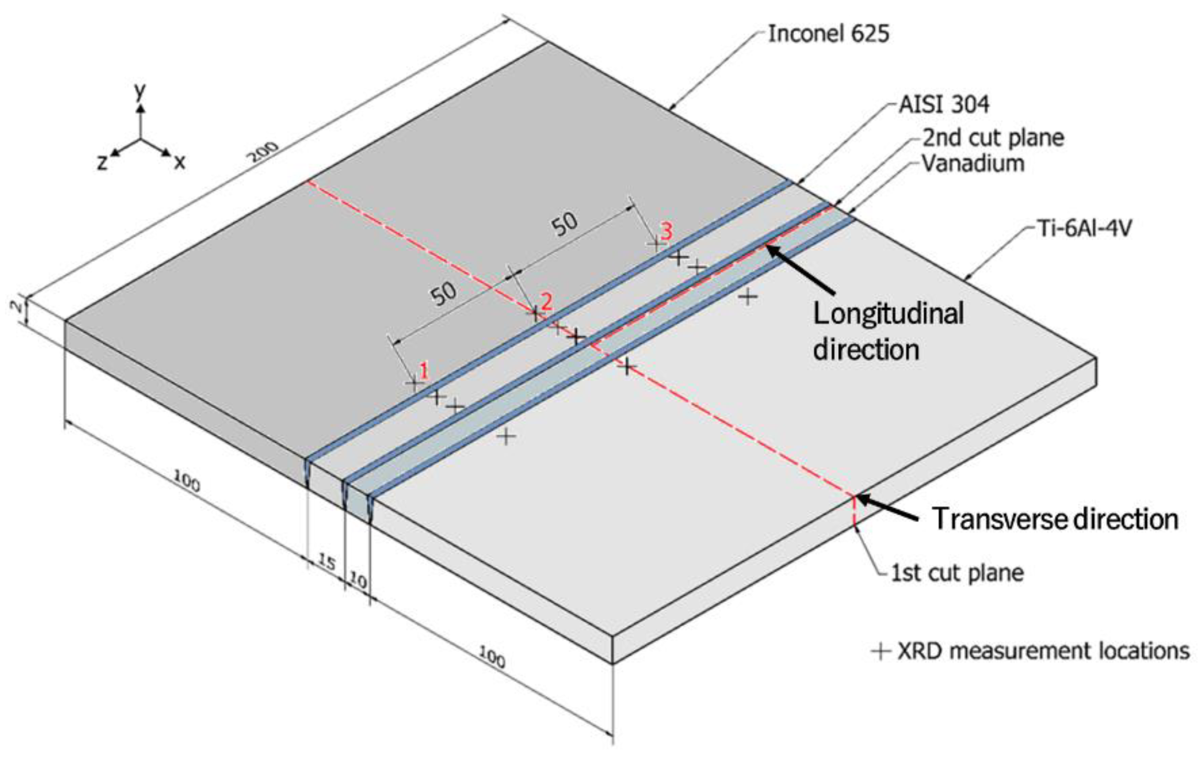
Welded joints were manufactured using an Ytterbium Fiber Laser System (YLS-4000-CT) with the following main characteristics: Maximum output power 4200 W at 1070 nm, optical fiber diameter 100 µm, mobile optics with 250 mm focal length, divergence 50 mrad, and beam product 3 mm mrad. The welding head was equipped with a wobbling device that conveys oscillatory movements to the focal spot to improve the joint quality by means of two galvanometric mirrors. The welding setup is displayed in Figure 1. Two butt-welded specimens were manufactured, with the same welding conditions, by interposing between 2-mm-thick sheets of Titanium grade 5 and two inserts of Inconel 625: One in pure Vanadium, 10 mm large, and one in stainless steel AISI 304, 15 mm large. Full penetration, in a single pass without filler material, was obtained using a laser power of 1750 W and a laser spot diameter of 250 µm. The three welds were made using different welding speeds: 40 mm/s at the Inconel 625/AISI 304 interface; 30 mm/s at the AISI304/Vanadium interface, with the wobbling of the laser spot set to 500 Hz frequency and 0.5 mm amplitude; 45 mm/s at the Vanadium/Ti6Al4V interface. Argon was applied to protect the melt and welded material and to suppress plasma, as shown in Figure 1. A schematic drawing of the welded plates along with their dimensions is depicted in Figure 2.

2.2. Residual Stresses

The residual stress state of the dissimilar welded joints was evaluated both on the surface and in depth to predict the fracture zone.
First, surface residual stresses, both longitudinal and transverse to the weld seams, were measured using X-ray diffraction. Thereafter, with the purpose of extending the investigation in depth as well, longitudinal residual stresses along the cross section were evaluated using the contour method. Finally, to complete the residual stress characterization and to consider fatigue test conditions, where the load is applied along the transverse direction, this component of residual stresses was also investigated. Due to the fact that the contour method is a destructive measurement technique, the plane along which the second cut is made was carefully chosen. As reported in the following sections, the surface measurements by X-ray diffraction and the longitudinal residual stress map obtained by the contour method revealed that the most critical area was at the interface between AISI 304 and Vanadium; which has the lowest mechanical strength (Table 2); therefore, the second cut was carried out in the Vanadium insert near the weld with the stainless steel.
To investigate surface residual stresses, X-ray diffractometry measurements were carried out. A Xstress 3000 G3R X-ray diffractometer by Stresstech (Rennerod, Germany) was used to measure both longitudinal and transverse surface residual stresses. It was instrumented with a Ti tube (λ = 0.274851 nm) for Titanium grade 5, and with a Cr tube (λ = 0.22897 nm) for Inconel 625 and AISI 304. Residual stresses were evaluated at three different points for each material composing the dissimilar joint, except for Vanadium for which the measurement could not be performed due to instrumental limitations. Each measurement point was located approximately 0.5 mm from the weld seams, as shown in Figure 2. The sin2ψ method was applied according to UNI EN 15305 standard [44]. The experimentally measured peak profile was interpolated by Pearson VII function, which allowed for the identification of the diffracted intensity, the K-alpha 1 position of the diffraction peak, and the width of the peak itself. Table 3 lists the parameters used to perform X-ray diffraction measurements.
The implementation of the contour method complied with the following steps: Specimen cuts were performed using wire electric discharge machining (EDM), the contours of the cut surfaces were acquired using fringe projection. Contour data were processed and finally a finite element analysis was performed [42,50]. Standard contour method procedure was used to map longitudinal residual stresses along the first cut plane, which divides the welded plate in half along the transverse direction (Figure 2) [42,44,50,51]. Conversely, the new approach for asymmetric stiffness cuts, reported in [52], was applied for the second cut, which separated the welded joint into two parts that did not possess mirror symmetric stiffness (Figure 2). Furthermore, the original transverse residual stresses, in the plane of the second cut, were obtained by elastic superposition of the calculated stresses relaxed from both cuts [53].
Each contour cut was performed using an Agiecut Classic 2S wire EDM machine (GF Machining Solutions, Biel, The Switzerland) with a 250-µm-diameter brass wire and skim cut settings, submerging the specimen with deionized water and clamping it symmetrically with fixtures placed as close as possible to the cut line to minimize deformation during relaxing of residual stresses [44,50,51,54]. Moreover, to assess the longitudinal residual stresses, the plate was divided in half along a plane transverse to the three welds. The second cut, for transverse stresses evaluation, was parallel to the weld beads and crossed the Vanadium insert at a distance of 0.5 mm to the weld with the stainless steel, as shown in Figure 2. Before measuring the surface profile, the cut parts were kept in a temperature-controlled laboratory until reaching thermal equilibrium with the environment. In this study, rather than using a coordinate measurement machine, the measurement of the cut surfaces was achieved using fringe projection, a full-field optical technique that shortens the time of this phase of the contour method [42,54,55]. The measurement setup, consisting of a fringe projector, a camera with resolution of 2 MPix and a computer, is shown in Figure 3.
The processing of the two point clouds obtained from the first cut was carried out following the same procedure reported in [42]. A three-dimensional elastic Finite Element (FE) model of the cut part of the sample was built using ABAQUS® software (Dassault Systèmes, Vélizy-Villacoublay, France) and applying the mechanical properties reported in Table 2. C3D8R elements were used with dimension of 0.1 × 0.1 × 0.1 mm3 for the first and second cut planes. The sign of the averaged and smoothed contour of the first cut was reversed, then this point cloud was imposed to the FE model as initial boundary displacement. To process the clouds of the second cut, the procedure outlined in [52] was adopted. According to this methodology, the point clouds are not averaged before back-calculating the residual stresses, as in the standard contour method, which does not allow for the contribution of shear stresses to be eliminated. Conversely, the two contours are considered separately, they are smoothed and then applied to distinct FE models of the two cut parts with side-specific stiffnesses. After FE analyses, the back-calculated stresses are averaged to remove shear stress errors. Finally, as mentioned above, the uncut transverse residual stresses were reconstructed using the superposition of results from the first and second cut [53].

2.3. Fatigue Testing

Fatigue tests were performed with an Italsigma servo-hydraulic testing machine (Italsigma Srl, Forli, Italy) equipped with a 25 kN load cell, at a frequency of 10 Hz. An infrared (IR) camera (FLIR Systems SC640 IR camera, with a resolution of 640 × 480 pixels, (Teledyne FLIR LLC, Wilsonville, OR, USA) was employed to monitor the surface temperature of the specimen during each fatigue test. The specimens were black painted to enhance their emissivity. The thermograms were captured at 1 frame each 30 s by FLIR ResearchIR Max 4.4 software (Teledyne FLIR LLC, Wilsonville, OR, USA). Tests were performed using a load ratio R = 0.1 to avoid compression stresses, which could affect the results causing compression instability [56]. Given that the weld is a weak point of the specimen, no dog-bone sample shapes were needed.

2.4. Failure Analysis

Fractographies were carried out by both Optical Stereomicroscope (OM) and Scanning Electron Microscope (SEM). The former is a Leica Microsystems M165C stereomicroscope (Leica Microsystems GmbH, Wetzlar, Germany); the latter is a Hitachi TM3030 plus (Hitachi, Tokyo, Japan) equipped with Thermo Scientific NORAN System 7 X-ray Microanalysis System (ThermoFisher Scientific, Waltham, MA, USA)). Energy Dispersive X-ray Analyses (EDS) were carried out by point-and-shot spectrum, line-scan and surface map tools to assess the elemental composition of the fracture surface and to evaluate whether the crack path was affected by the presence of some particular phases formed after the welding process. The surface topographies and the average values of surface roughness (Sa) were measured by a confocal microscope (Leica DCM 3D, Leica Microsystems, Wetzlar, Germany). Statistical analyses were made on an area of 0.64 × 0.5 mm2 according to ISO 25178, by means of LeicaMap 6.2 software (Leica Microsystems GmbH, Wetzlar, Germany). These scansions were obtained by an EPI 20X-L objective in LeicaScan DCM 3D software (Leica Microsystems GmbH, Wetzlar, Germany). The z-scan covered a height of 360 μm with a z-step of 6 μm, being z the orthogonal direction to the fracture surface.

3. Results

3.1. Residual Stresses

The measurement and analysis of residual stresses provide a variety of information. Prior to fatigue tests, it allows for the presence of stress concentration zones to be highlighted, and consequently to predict possible fracture zones. Whereas, after the analysis of fracture surfaces, knowing residual stresses supports a better understanding of the main mechanisms and causes of failure.
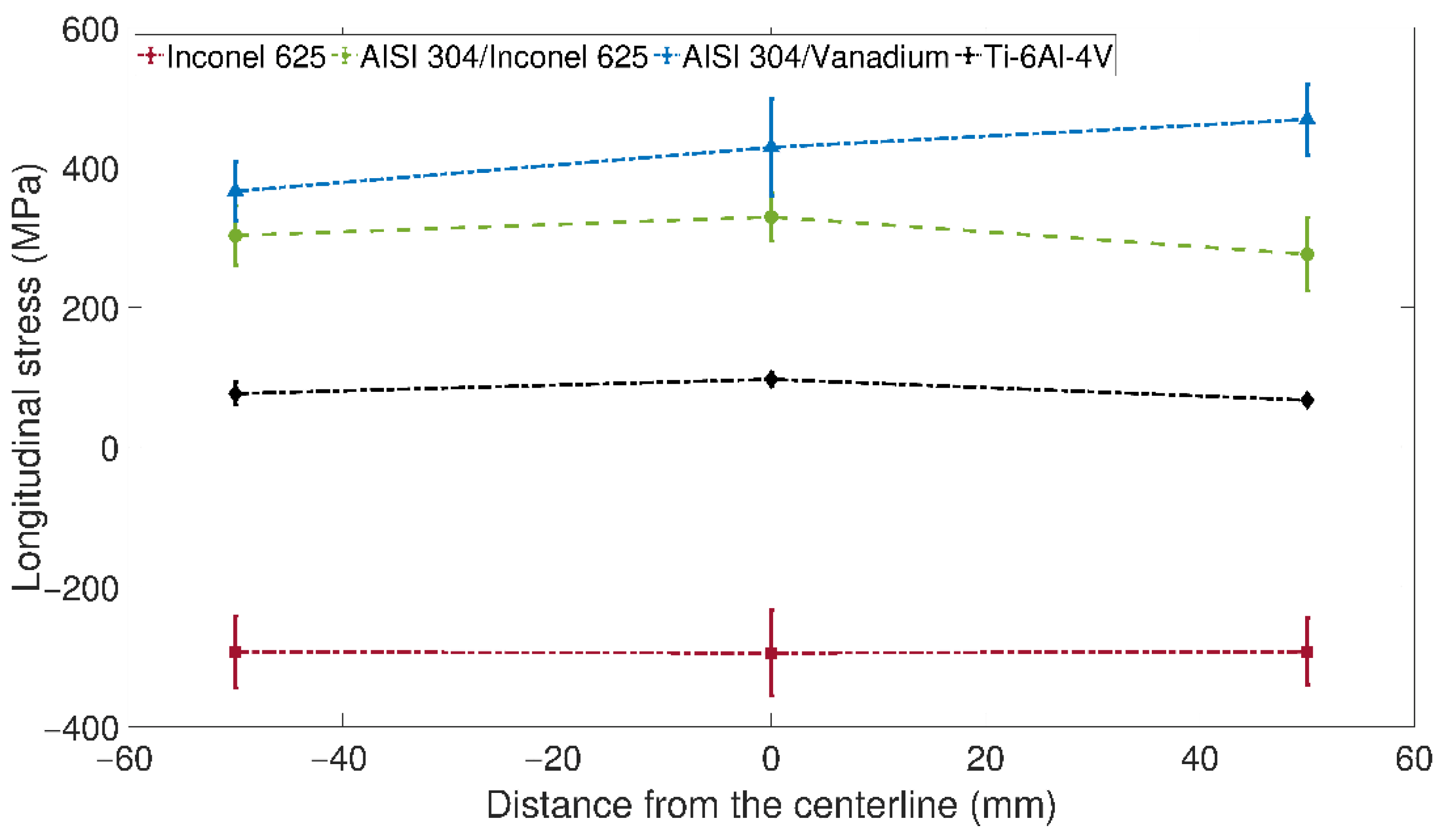
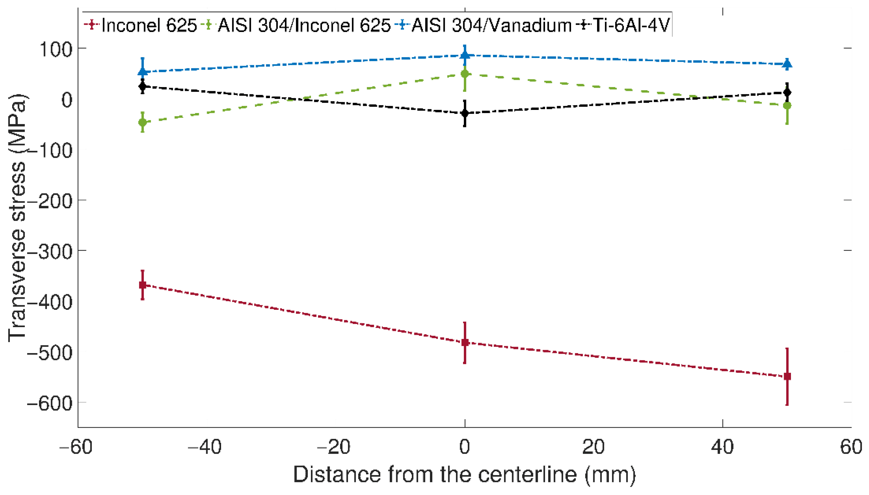
Surface longitudinal and transverse residual stresses, measured by X-ray diffraction at the spots marked in Figure 2, are given in Figure 4 and Figure 5, respectively.
Figure 4 shows high compression on the surface of the Inconel 625 reaching −300 MPa, while the highest tensile stresses occur in the AISI 304 at the weld with the Vanadium. The transverse residual stresses, reported in Figure 5, highlight extremely high compressive stresses, up to −550 MPa, in the Inconel. Furthermore, in the Ti6Al4V and in the AISI 304 at the interface with the Inconel, slight compression or low tension is detected, whereas, at the weld with the Vanadium, the AISI 304 is always characterized by surface tension, ranging from 60 to 90 MPa.
The procedure developed by Prime et al. [57] was adopted in the implementation of the contour method to select the cubic fitting splines which minimize the average stress uncertainties over the whole stress maps. To evaluate these uncertainties, the number of knots along the largest dimension of the cross sections was varied uniformly, while along the thickness only two knots were used to avoid overfitting. The average stress uncertainties with the corresponding knot spacing of the cross sections’ largest dimension are reported in Table 4. For the second cut, the average stress uncertainties were calculated separately, where side A corresponds to the Inconel 625 side of the cut part, while side B is the Ti6Al4V side. In addition, the uncertainty for the final map of the transverse residual stresses was estimated by averaging the stress maps of the two sides and then applying the procedure outlined in [57].
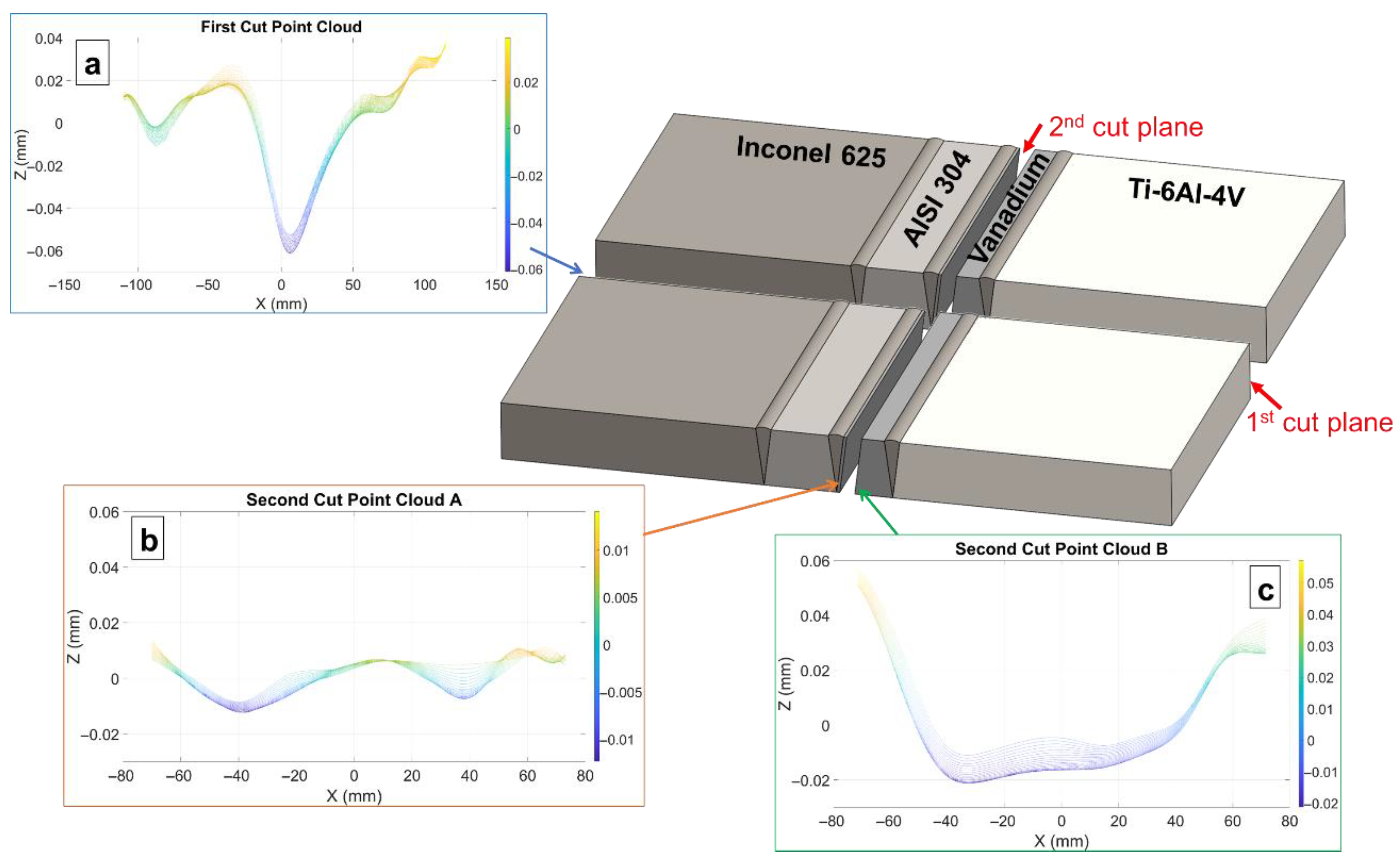
The smoothed surface profiles of the first cut and of the two sides of the second cut are displayed in Figure 6. The peak-to-valley difference of the first cut was about 100 µm, for the second cut on the side with the Titanium Grade 5 it was around 70 µm, while on the side containing the Inconel 625, the stiffer side, it was only 30 µm. Therefore, this large asymmetry in the normal displacements of the second cut must be taken into account by following the methodology reported in [52], rather than using the standard procedure of the contour method.
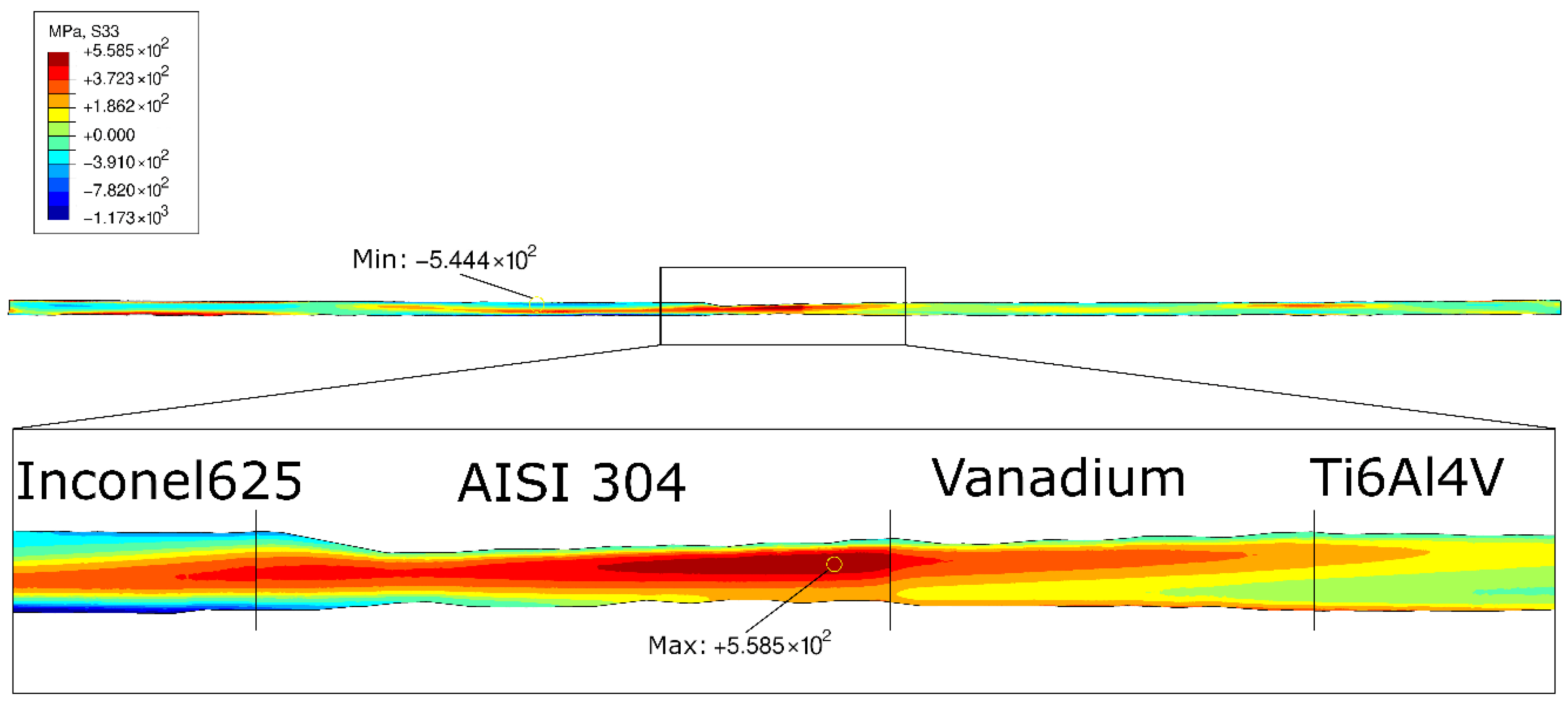
The 2D longitudinal residual stress map is shown in Figure 7. There are harmful tensile residual stresses in the area of the three welds, balanced by compression in the base metals. Notably, the most affected area by detrimental tensile residual stresses is the weld between the stainless steel and Vanadium, where the maximum value of nearly 560 MPa is reached. Furthermore, in the weld between Inconel 625 and AISI 304, high compression is recorded on the surface of the Inconel 625 side extending from the joint toward the base metal.
In dissimilar welds, residual stresses are generated not only by the welding process, but also by the different CTEs of the two welded materials [30,31]. During cooling from the melting temperature, a larger shrinkage affects the material with the higher CTE, but this is restrained by the parent material and the material with the lower CTE, which undergoes a lower contraction. Once the cooling process is over and room temperature is reached, the material with higher CTE has experienced greater shrinking limitation and consequently is subjected to higher tensile residual stresses. CTEs of the materials are reported in Table 5. The greatest variation in thermal properties is found at the weld between the AISI 304 and the Vanadium. Indeed, the maximum tensile stress is located in the stainless-steel insert right next to the interface with the Vanadium.
From surface residual stress measurements, high tensile stress was found in the weld between the stainless steel and Vanadium. This finding was confirmed by the analysis of longitudinal stresses in depth using the contour method. Moreover, Vanadium is the most critical material since it is characterized by the lowest ultimate tensile stress.
Figure 8 shows the map of the transverse residual stresses acting in the Vanadium insert, measured by asymmetric stiffness analysis and superimposing the relaxed transverse stresses from the first cut [52,53]. The end of the welded plate is stress free, while from about 8 mm distance up to the first cut plane tensile residual stresses occur in the core of the insert, whereas compression affects the surface. The maximum tensile residual stress is about 350 MPa. A zone of lower tension, ranging between 60 and 120 MPa, can be seen near the first cut plane; however, no cracks or other sources of stress relaxation were found by visual inspection.
Furthermore, specimens cut in the central plate region, where significantly lower transverse tensile stresses are recorded, might be characterized by better fatigue behavior, if compared to those obtained from the area where the highest transverse tensile stresses were generated. As a consequence, it is possible that the interface between Vanadium and AISI 304 would not be the failure zone. Moreover, compressive residual stresses at the surface, aligned with the loading direction of the fatigue tests, are beneficial for fatigue life. Indeed, as reported in the fatigue results section, the fatigue strength in terms of stress range was found to be high, thus confirming the good quality of the joint.
In the outer region of the maps, high magnitude residual stresses can be found (e.g., −1173 MPa in Figure 7) owing to errors related to splines extrapolation; therefore, they should not be considered [58]. In fact, the maxima and minima stress values in Figure 7 and Figure 8 do not include results from these extrapolated regions.
From the analysis of the residual stresses, it is shown that the most critical area is the interface between AISI 304 and Vanadium, where the highest values of the residual stresses occur, and the most critical material is Vanadium, which has the lowest mechanical strength (Table 2).

3.2. Fatigue

The surface temperature was monitored by an IR camera during each test. A typical temperature map during fatigue tests is shown in Figure 9. The IR technique proved its suitability in identifying the failure zone, which is detected as the area subjected to the maximum temperature. Indeed, the red dot in the images indicates the hottest point (in correspondence of the Vanadium/Ti6Al4V for test 4) which is the site of crack initiation and final fracture of the specimen. The thermographic analyses confirm the results obtained by the evaluation of the residual stresses: Vanadium is the critical material in the dissimilar welded joints.
The parameters used and the results obtained are shown in Table 6 and are retrieved from [43]. The applied stress range Δσ was calculated considering the nominal stress on the cross-net area to simplify its evaluation. However, in some cases, structural or local approaches in the presence of welds [13,59] could be preferred.
Table 6 reports the fracture zone, where “V-SS” is the interface between Vanadium and AISI 304 stainless steel, while “Ti-V” is the interface between Ti6Al4V alloy and Vanadium. As reported in Table 6, the fatigue tests confirm the results, obtained by analyses of residual stress and thermographic images, that the fracture region is related to the presence of Vanadium, which has the lowest tensile strength. The Δσ-N curve is shown in Figure 10, where arrows are referred to the run-out tests.
Although the residual stress analysis correctly identified the most critical material where failure always occurs, the failure originated in the zone of maximum residual stresses only on half of the specimens. Several reasons could be responsible for this phenomenon. First, this observation highlights that residual stresses are not the only factor affecting failure, and it is therefore necessary to perform a thorough fractographic analysis. As can be seen in Table 6, the contribution of a plurality of factors is further confirmed by the absence of a clear correlation between the applied stress range and the failure zone. Therefore, the residual stresses affect this area. For similar welded joints, numerical analyses on the effect of residual stresses on fatigue life have shown that high stress ranges produce a relaxation of residual stresses, as a result of plastic strain, thus their influence is mitigated. Some researchers have found that this relaxation occurs almost exclusively in the very early cycles [60]. While others have reported that residual stresses are significantly lowered in the first cycle due to large plastic deformations, and in the following cycles these decrease progressively due to fatigue damage [61]. The major impact of residual stresses on fatigue life over the high number of cycles was also observed by Zhang et al. in [38] through numerical simulations of a T-joint between dissimilar steels. Due to the complex nature of the dissimilar joint under investigation, this correlation between the applied stress range ΔϬ and residual stresses is not apparent. In fact, the Ti-V interface experiences a lower residual stress state than V-SS interface, but it turns out to be a fracture zone even for the low applied stress range ΔϬ, when instead residual stresses should be the predominant fracture cause (Table 6). However, it should also be noted that specimens 4, 5, and 6 were extracted from the central portion of the plate, where transverse residual stresses are lower, and thus other causes may have been responsible for the fracture at the interface between Vanadium and Ti6Al4V.
The value of the fatigue strength in terms of stress range Δσ, as evaluated in [43], is in the range between 160 and 170 MPa. The value confirmed the good quality of the obtained joints, since the fatigue strength is higher than the value of tensile strength (145 MPa), obtained during static tests which were carried out on laser-welded Ti-Inconel joint [22].

3.3. Failure Analysis

Starting from the fatigue test results, the fracture surface topography of two specimens (Figure 11) subjected to the same value of stress range Δσ = 200 MPa were analyzed by a confocal microscope. This choice was related to the significantly different fatigue life experienced by the specimens, as well as to the different occurrence of the fracture zone (Table 7).
The parameters related to the surface topography are reported in Table 7 and highlight the higher roughness (Sa) of V-SS interface, as well as inverted values of the skewness (Ssk). Considering that the skewness is the measure of the profile asymmetry with regard to the mean line, it is expected that the surface of specimen 7 is very unsmoothed. Nevertheless, Persistent Slip Bands (PSB) and a number of irregular crack planes can be seen on the surface (Figure 12b). The fatigue life could have been affected by the presence of voids on the crack path. As measured by SEM observations (Figure 12b), the dimensions of the discontinuities are similar to those analyzed in [62].
Specimen 6 experienced an initial ductile mode in correspondence of a large void (about 500 mm, Figure 12a), while the fast propagation was influenced by other voids, which produced a brittle and flat surface. The initial ductile behavior can be related to the presence of Vanadium at the fracture interface.
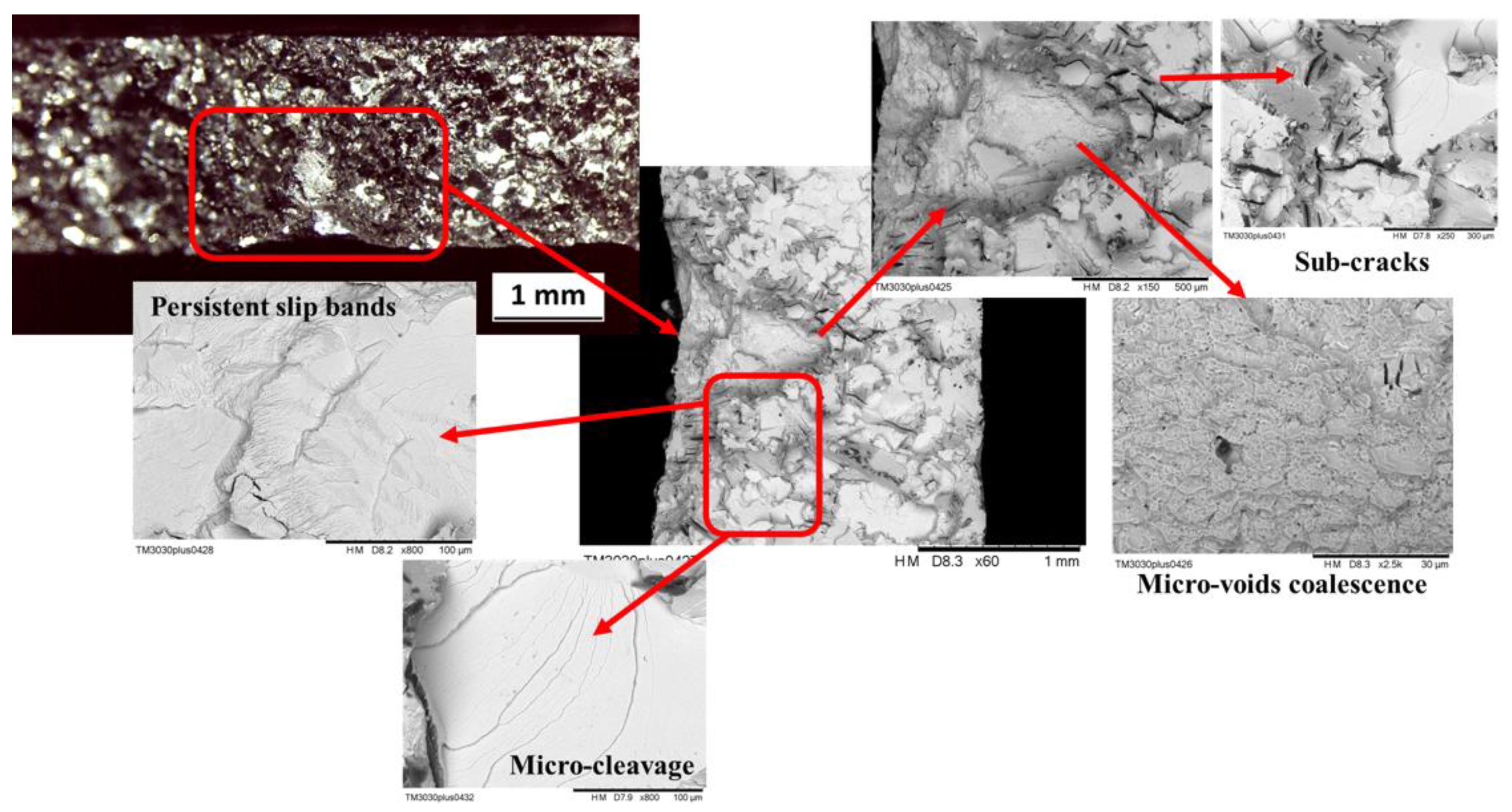
Microcleavage crack growth is a low energy process and therefore an undesirable fatigue crack growth mechanism. As shown in Figure 12b, the microcleavage involves the fracture along specific crystallographic planes, which is the reason for its transcrystalline origin. The surface appears flat and contains several parallel ridges which represent the cleavage planes.
Analyzing in depth the elemental composition of the fracture surface of specimen 7 (Figure 13), the brittle behavior is due to the presence of voids, considering that EDS did not highlight any relevant modification. In addition to the occurrence of voids, as Panontin and Hill highlighted in [63], the onset of brittle fracture is strongly influenced by the residual stress field, which decrease the J-value for brittle fracture initiation as a consequence of an increase in constraint. In fact, the highest harmful residual stresses occurred at the weld between Vanadium and AISI 304.
The specimens subjected to Δσ = 220 MPa experienced very different fatigue lives (Table 8). In this case, the fracture mode is ductile for the Ti-V interface and brittle for the V-SS.
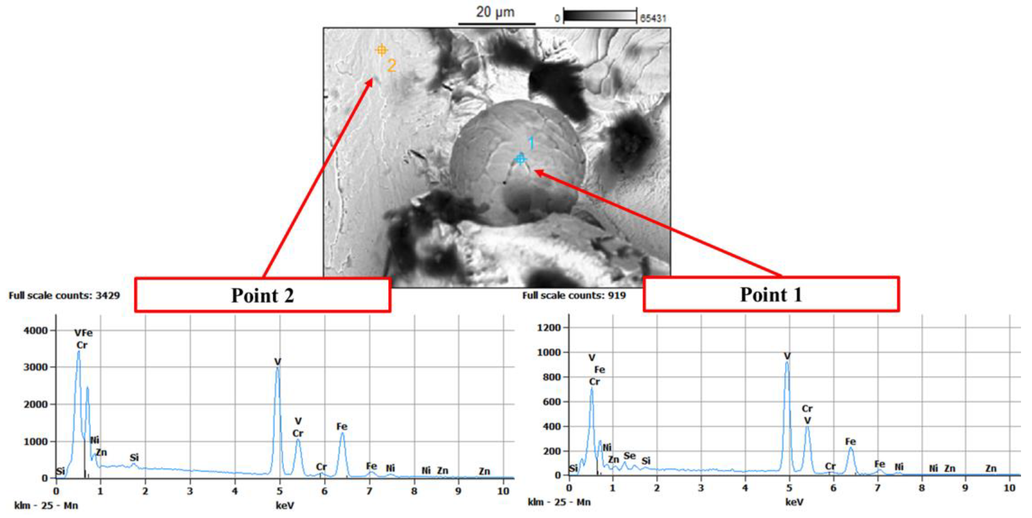
In specimen 8, the fracture initiation occurred near the surface of the wider side, where some pores were detected by SEM analysis (Figure 14a). The fracture surface is characterized by a ductile mode, with fatigue striations, visible also at a magnitude of 2000X, corroborating the assumption that the crack initiation occurred as a result of notch effect due to the defects. Nevertheless, the crack propagation was triggered by some discontinuities, about 30 mm wide, found on the fracture surface (Figure 14b). EDS spectrum supported the hypothesis that crack path was affected only by defects, as the elemental composition is stable, highlighting elements belonging mainly to the Vanadium phase, considering that its Ka second peak is higher than the Titanium (Figure 14b). The first peaks (La1) are superimposed, due to their proximity in the periodic table of the elements. According to both the shape and the chemical composition of the spherical void, it follows that the void is derived from a gas bubble trapped during the welding process and it is not a slag inclusion that flew out during failure.
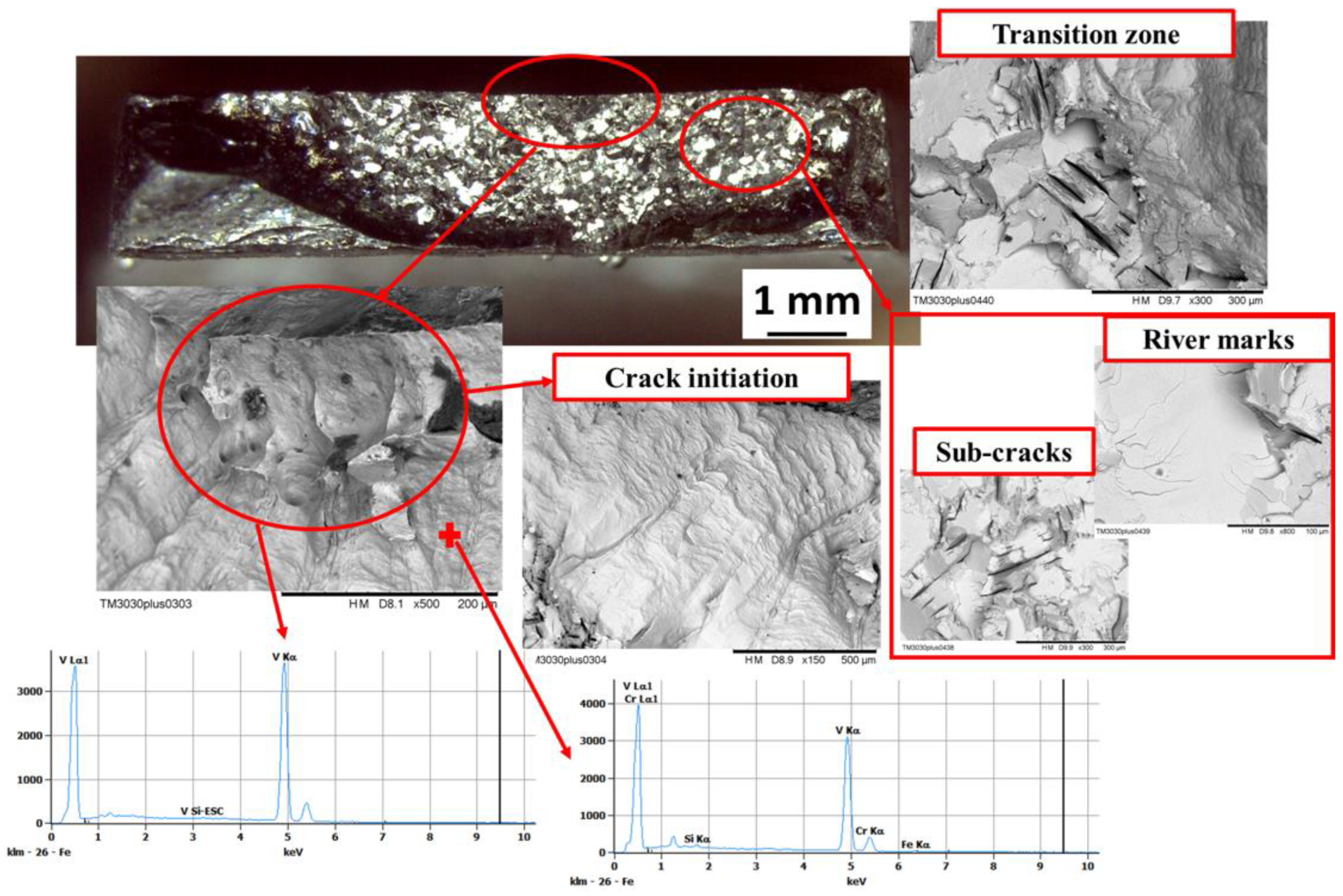
Specimen 9 experienced similar brittle behavior of specimen 7. The fracture surface is characterized by the presence of an initiation site due to a wide notch effect near the external surface of the specimen. Crack initiation started in a ductile/shear mode on the Vanadium phase. A transition zone follows, in which the crack path became fast and flat (tensile mode), experiencing sub-cracks and river marks, that are the evidence of a brittle and fast rupture phase (Figure 15).
As shown in Figure 10, the stress value which represented the boundary between runout and finite cycles to fracture is Δσ = 170 MPa (specimen 3). The fracture occurred at the V-SS interface, with an interesting mixed mode (Figure 16). The macroscopic appearance of the fracture surface is brittle, but, at higher magnitude observed by SEM, it is possible to highlight the presence of slip bands pile-up and micro-voids coalescence (ductile mode), followed by a fast micro-cleavage mechanism (brittle mode).
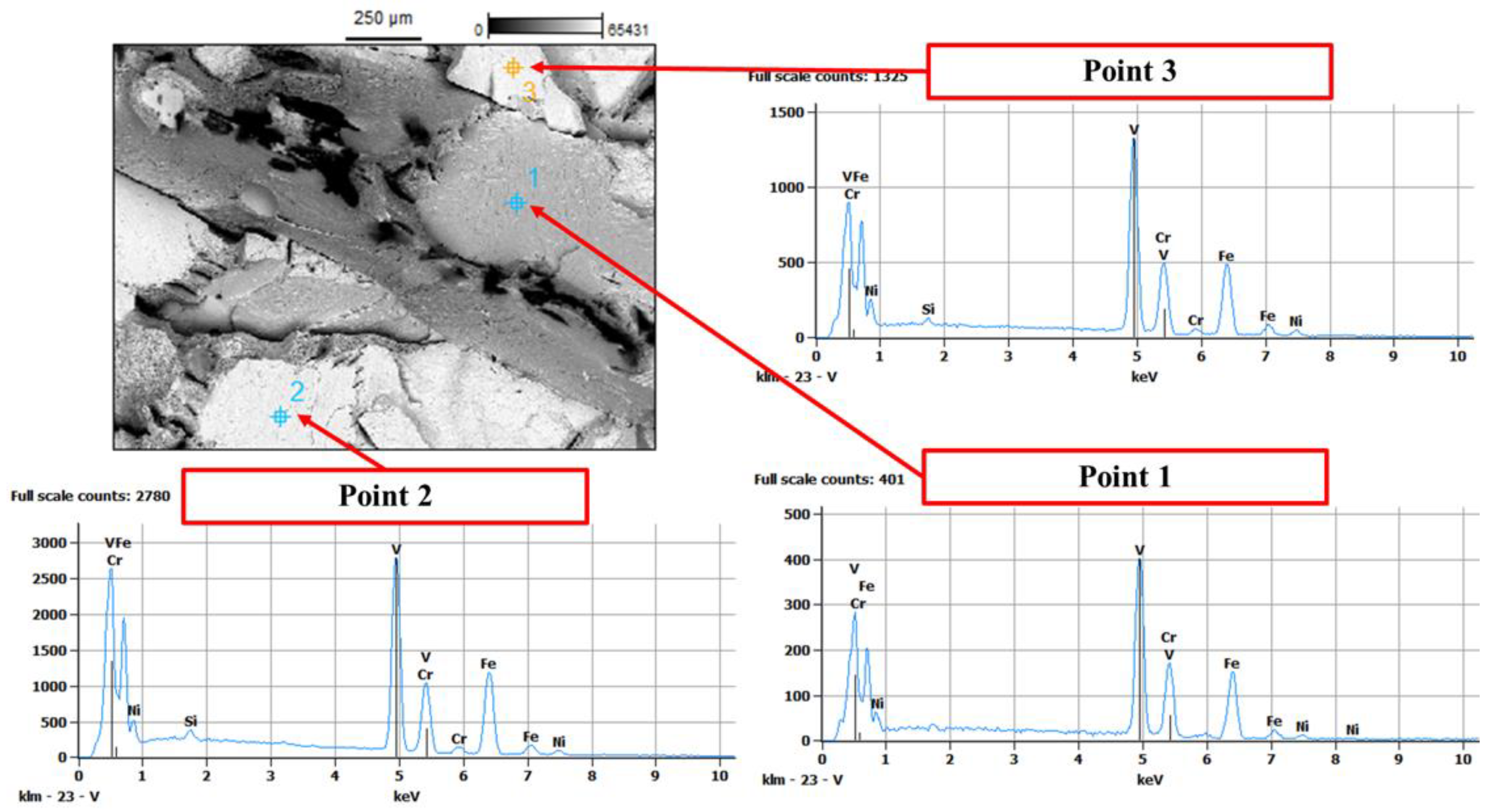
This complex mechanism can be explained by analyzing the findings of EDS (Figure 17). The initiation site is on the Vanadium phase, which has lower mechanical strength than steel. The change in crack path was triggered by the presence of intermetallic phases, that enriched the area in which the ductile mode was modified in the brittle one. The latter occurred on the steel interface, which, as reported above, is subjected to very high tensile residual stresses due to the welding process.
The variation in the crack path due to instable phases is testified by the presence in the same spectrum of Vanadium and Chromium, Iron, Nickel, and traces of Silicon. The analyses of all failed specimens are summarized in Table 9. It is evident how the residual stress field severely influenced the fracture mode of the fatigue-tested specimens, predominantly causing brittle fracture where the residual stresses were higher [58].
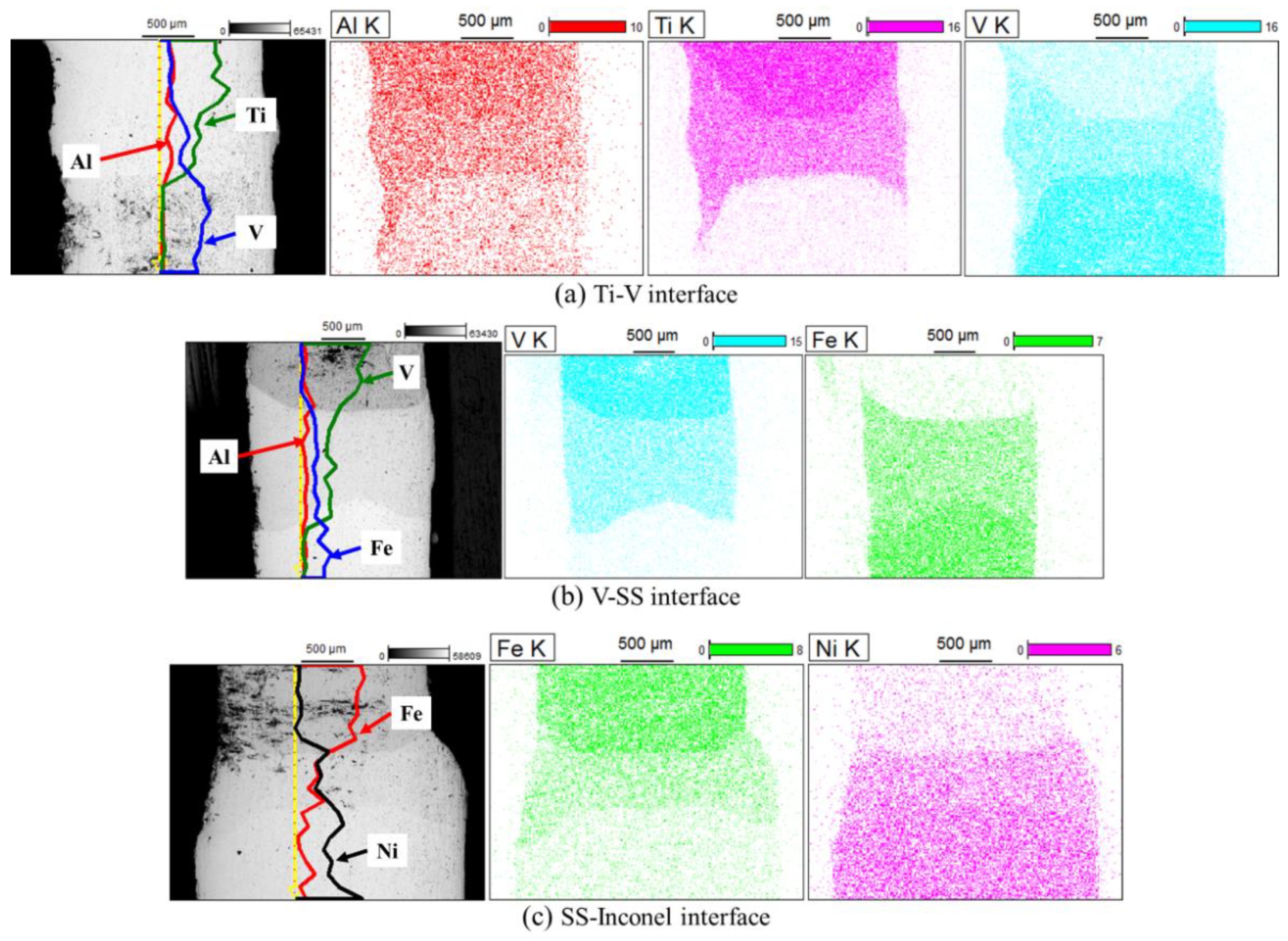
The chemical composition of a runout specimen (specimen 1) was analyzed by recording the line-scan of the longitudinal side and the map on the whole lateral side (Figure 18).

4. Conclusions

The present research work proposed an experimental methodology to assess the mechanical quality of dissimilar joints by investigating the fatigue behavior, the residual stress field and the fracture modes, highlighting the intrinsic correlation of all the information collected.
First, a comprehensive evaluation of the residual stress state was carried out on a Ti6Al4V/Inconel 625 dissimilar welded joint by measuring it at both surface and depth, exploiting X-ray diffraction and multiple-cut contour method, respectively.
Measurements revealed that harmful tensile longitudinal stresses are located in the three-welds region, balanced by compression in the base metals. The most critical area, exhibiting the highest tensile residual stresses, was the interface between AISI 304 and Vanadium, where the greatest difference in the CTEs occurred. Furthermore, the most critical material, where the fracture was more likely to occur, was the Vanadium, which was affected by high tensile residual stresses and has the lowest mechanical strength.
The fatigue tests, performed at load ratio R = 0.1, confirm the location of the fracture zone, predicted by the analysis of the residual stress and the thermographic images; the fracture zone is related to the presence of Vanadium. However, no direct correlation was found between the applied stress range and the residual stresses. This emphasizes that the fatigue failure mechanisms of dissimilar joints are not dependent on a single factor, but on a set of concurrences. The value of the fatigue strength, obtained by the S-N curve, is particularly promising and confirms the good quality of the proposed dissimilar joints with the two intermediate inserts.
Failure analysis was performed to evaluate the fracture modes of specimens tested at the same Δσ. These specimens experienced different modalities and fatigue lives. It was found that the brittle fracture was mainly due to the high residual stresses on the stainless-steel side, which exhibited micro-cleavage mechanism, with the presence of PSB, sub-cracks, and river marks. At the optical microscope, the appearance of fracture surface is the typical rock candy one. In these cases, the crack initiation is due to voids (pores).
Persistent slip bands were detected at stress range Δσ values of 170 and 200 MPa on the specimens that showed brittle fractures. Therefore, fatigue life could be related to the presence of this mechanism, due to the high local plastic deformation. At higher value of stress range Δσ (220 MPa), the fatigue life seems to be not related to the fracture mode but to a large number of pores cluster on the crack path.
Although the fatigue results showed high mechanical performance, it is worth mentioning that the studied welding process needs to be further optimized to reduce the occurrence of defects. Nevertheless, by means of the proposed comprehensive experimental analysis, which involves careful evaluation of residual stresses and fracture surfaces, it is evident that the components produced by this technology need to be subjected to treatments that promote stress relief by a thermal or mechanical process (shot peening).

Author Contributions

Conceptualization, P.C., G.P. (Giulia Palomba), G.E., V.M., and G.P. (Giovanni Pappalettera); methodology, P.C., G.E., S.C., V.M., and G.P. (Giovanni Pappalettera); formal analysis, S.C.; investigation, P.C., G.E., S.C., and V.M.; data curation, S.C.; writing—original draft preparation, P.C. and S.C.; writing—review and editing, P.C., G.P. (Giulia Palomba), G.E., V.M., and G.P. (Giovanni Pappalettera); visualization, G.P. (Giulia Palomba), G.E., and S.C., supervision, G.P. (Giovanni Pappalettera); project administration, C.C.; funding acquisition, C.C. All authors have read and agreed to the published version of the manuscript.

Funding

This research was funded by the Italian Ministry of Education, University and Research (MIUR), grant PRIN-2015PN8CEA “Characterization of Laser/Electron—Beam welded JOINTs made by dissimilar materials for aeronautical applications—CLEBJOINT”.

Institutional Review Board Statement

Not applicable.

Informed Consent Statement

Not applicable.

Data Availability Statement

Not applicable.

Conflicts of Interest

The authors declare no conflict of interest.

References

  1. Fang, Y.; Jiang, X.; Mo, D.; Zhu, D.; Luo, Z. A review on dissimilar metals’ welding methods and mechanisms with interlayer. Int. J. Adv. Manuf. Technol. 2019, 102, 2845–2863. [Google Scholar] [CrossRef]
  2. Wu, T.; Ma, Y.; Xia, H.; Geng, P.; Niendorf, T.; Ma, N. Measurement and simulation of residual stresses in laser welded CFRP/steel lap joints. Compos. Struct. 2022, 292, 115687. [Google Scholar] [CrossRef]
  3. Farabi, N.; Chen, D.L.; Zhou, Y. Microstructure and mechanical properties of laser welded dissimilar DP600/DP980 dual-phase steel joints. J. Alloys Compd. 2011, 509, 982–989. [Google Scholar] [CrossRef]
  4. Vaidya, W.V.; Horstmann, M.; Ventzke, V.; Petrovski, B.; Koçak, M.; Kocik, R.; Tempus, G. Improving interfacial properties of a laser beam welded Dissimilar joint of aluminium AA6056 and titanium Ti6Al4V for aeronautical applications. J. Mater. Sci. 2010, 45, 6242–6254. [Google Scholar] [CrossRef] [Green Version]
  5. Chen, H.C.; Pinkerton, A.J.; Li, L. Fibre laser welding of dissimilar alloys of Ti-6Al-4V and Inconel 718 for aerospace applications. Int. J. Adv. Manuf. Technol. 2011, 52, 977–987. [Google Scholar] [CrossRef]
  6. Zhou, Z.; Gao, X.; Zhang, Y. Research Progress on Characterization and Regulation of Forming Quality in Laser Joining of Metal and Polymer, and Development Trends of Lightweight Automotive Applications. Metals 2022, 12, 1666. [Google Scholar] [CrossRef]
  7. Handa, V.; Goyal, P.; Sehgal, S. Low Cost Joining of Inconel 625 and Super Duplex Stainless Steel 2507 through Novel Technique. J. Mater. Eng. Perform. 2022, 1–6. [Google Scholar] [CrossRef]
  8. Handa, V.; Goyal, P.; Goyal, S. Application of graphite rods in producing Inconel 625 (UNS N06625) joints through the use of microwave radiation energy. Indian J. Eng. Mater. Sci. 2022, 29, 378–384. [Google Scholar] [CrossRef]
  9. Hao, X.; Dong, H.; Xia, Y.; Li, P. Microstructure and mechanical properties of laser welded TC4 titanium alloy/304 stainless steel joint with (CoCrFeNi)100-xCux high-entropy alloy interlayer. J. Alloys Compd. 2019, 803, 649–657. [Google Scholar] [CrossRef]
  10. Liu, H.; Aoki, Y.; Aoki, Y.; Ushioda, K.; Fujii, H. Principle for obtaining high joint quality in dissimilar friction welding of Ti-6Al-4V alloy and SUS316L stainless steel. J. Mater. Sci. Technol. 2020, 46, 211–224. [Google Scholar] [CrossRef]
  11. Liu, G.; Gao, X.; Peng, C.; Huang, Y.; Fang, H.; Zhang, Y.; You, D.; Nanfeng, Z. Optimization of laser welding of DP780 to Al5052 joints for weld width and lap-shear force using response surface methodology. Opt. Laser Technol. 2020, 126, 106072. [Google Scholar] [CrossRef]
  12. Quazi, M.M.; Ishak, M.; Fazal, M.A.; Arslan, A.; Rubaiee, S.; Qaban, A.; Aiman, M.H.; Sultan, T.; Ali, M.M.; Manladan, S.M. Current research and development status of dissimilar materials laser welding of titanium and its alloys. Opt. Laser Technol. 2020, 126, 106090. [Google Scholar] [CrossRef]
  13. Corigliano, P.; Crupi, V. Review of fatigue assessment approaches for welded marine joints and structures. Metals 2022, 12, 1010. [Google Scholar] [CrossRef]
  14. Zhu, Z.; Lee, K.Y.; Wang, X. Ultrasonic welding of dissimilar metals, AA6061 and Ti6Al4V. Int. J. Adv. Manuf. Technol. 2012, 59, 569–574. [Google Scholar] [CrossRef]
  15. Seretsky, J.; Ryba, E.R. Laser Welding of Dissimilar Metals: Titanium to Nickel. Weld. J. 1976, 55, 121–208. [Google Scholar]
  16. Chatterjee, S.; Abinandanan, T.A.; Chattopadhyay, K. Microstructure development during dissimilar welding: Case of laser welding of Ti with Ni involving intermetallic phase formation. J. Mater. Sci. 2006, 41, 643–652. [Google Scholar] [CrossRef]
  17. Chatterjee, S.; Abinandanan, T.A.; Chattopadhyay, K. Phase formation in Ti/Ni dissimilar welds. Mater. Sci. Eng. A 2008, 490, 7–15. [Google Scholar] [CrossRef]
  18. Zhang, Y.; Gao, X.; You, D.; Jiang, X.; Ge, W. Investigation of Laser Butt Welding of AISI 304L and Q235 Steels Based on Numerical and Experimental Analyses. Metals 2022, 12, 803. [Google Scholar] [CrossRef]
  19. Pugacheva, N.B.; Orishich, A.M.; Volkova, E.G.; Makarov, A.V.; Senaeva, E.I.; Malikov, A.G. Role of ultra-fine intermetallic particles and martensite in strengthening of AISI 321/Cu/Ti laser welded joint. Mater. Charact. 2022, 185, 111702. [Google Scholar] [CrossRef]
  20. Gao, Y.; Huang, L.; An, Q.; Bao, Y.; Li, X.; Zhang, J.; Geng, L. Microstructure evolution and mechanical properties of titanium matrix composites and Ni-based superalloy joints with Cu interlayer. J. Alloys Compd. 2018, 764, 665–673. [Google Scholar] [CrossRef]
  21. Gao, Y.; Huang, L.; Bao, Y.; An, Q.; Sun, Y.; Zhang, R.; Geng, L.; Zhang, J. Joints of TiBw/Ti6Al4V composites- Inconel 718 alloys dissimilar joining using Nb and Cu interlayers. J. Alloys Compd. 2020, 822, 153559. [Google Scholar] [CrossRef]
  22. Gao, X.L.; Liu, J.; Zhang, L.J. Dissimilar metal welding of Ti6Al4V and Inconel 718 through pulsed laser welding-induced eutectic reaction technology. Int. J. Adv. Manuf. Technol. 2018, 96, 1061–1071. [Google Scholar] [CrossRef]
  23. Liu, J.; Liu, H.; Gao, X.L.; Yu, H. Microstructure and mechanical properties of laser welding of Ti6Al4V to Inconel 718 using Nb/Cu interlayer. J. Mater. Process. Technol. 2020, 277, 116467. [Google Scholar] [CrossRef]
  24. Shehbaz, T.; Khan, F.N.; Junaid, M.; Haider, J. Investigating nanoindentation creep behavior of pulsed-tig welded inconel 718 and commercially pure titanium using a vanadium interlayer. Metals 2021, 11, 1492. [Google Scholar] [CrossRef]
  25. Wojewoda-Budka, J.; Bugajska, M.; Guspiel, J.; Terlicka, S.; Bigos, A.; Wierzbicka-Miernik, A.; Szulc, Z. On Selected Properties of Inconel 625/Ti6Al4V Explosively Welded Clad. J. Mater. Eng. Perform. 2022, 31, 7080–7087. [Google Scholar] [CrossRef]
  26. Gao, F.; Sun, Z.; Yang, S.; Jiang, P.; Liao, Z. Stress corrosion characteristics of electron beam welded titanium alloys joints in NaCl solution. Mater. Charact. 2022, 192, 112126. [Google Scholar] [CrossRef]
  27. Crupi, V.; Guglielmino, E.; Risitano, A.; Taylor, D. Different Methods for Fatigue Assessment of T Welded Joints Used in Ship Structures. J. Ship Res. 2007, 51, 150–159. [Google Scholar] [CrossRef]
  28. Auwal, S.T.; Ramesh, S.; Yusof, F.; Manladan, S.M. A review on laser beam welding of titanium alloys. Int. J. Adv. Manuf. Technol. 2018, 97, 1071–1098. [Google Scholar] [CrossRef]
  29. Withers, P.J.; Bhadeshia, H. Residual stress: Part 2—Nature and origins. Mater. Sci. Technol. 2001, 17, 366–375. [Google Scholar] [CrossRef]
  30. Joseph, A.; Rai, S.K.; Jayakumar, T.; Murugan, N. Evaluation of residual stresses in dissimilar weld joints. Int. J. Press. Vessel. Pip. 2005, 82, 700–705. [Google Scholar] [CrossRef]
  31. Jenney, C.L.; Brien, A.O. (Eds.) Welding Handbook, 9th ed.; Woodhead Publishing: Sawston, UK, 2001; Volume 1, ISBN 0871716577. [Google Scholar]
  32. Schajer, G.S.; Ruud, C.O. Overview of Residual Stresses and Their Measurement. In Practical Residual Stress Measurement Methods; John Wiley & Sons, Ltd.: Hoboken, NJ, USA, 2013; pp. 1–27. [Google Scholar]
  33. Mujica, L.; Weber, S.; Pinto, H.; Thomy, C.; Vollertsen, F. Microstructure and mechanical properties of laser-welded joints of TWIP and TRIP steels. Mater. Sci. Eng. A 2010, 527, 2071–2078. [Google Scholar] [CrossRef]
  34. Ramkumar, K.D.; Kumar, P.S.G.; Krishna, V.R.; Chandrasekhar, A.; Dev, S.; Abraham, W.S.; Prabhakaran, S.; Kalainathan, S.; Sridhar, R. Influence of laser peening on the tensile strength and impact toughness of dissimilar welds of Inconel 625 and UNS S32205. Mater. Sci. Eng. A 2016, 676, 88–99. [Google Scholar] [CrossRef]
  35. Logesh, M.; Selvabharathi, R.; Thangeeswari, T.; Palani, S. Influence of severe double shot peening on microstructure properties of Ti 6Al-4V and Titanium Grade 2 dissimilar joints using laser beam welding. Opt. Laser Technol. 2020, 123, 105883. [Google Scholar] [CrossRef]
  36. Du, C.; Wang, X.; Hu, L. Microstructure, mechanical properties and residual stress of a 2205DSS/Q235 rapidly formed LBW joint. J. Mater. Process. Technol. 2018, 256, 78–86. [Google Scholar] [CrossRef]
  37. Scialpi, A.; De Giorgi, M.; De Filippis, L.A.C.; Nobile, R.; Panella, F.W. Mechanical analysis of ultra-thin friction stir welding joined sheets with dissimilar and similar materials. Mater. Des. 2008, 29, 928–936. [Google Scholar] [CrossRef]
  38. Zhang, W.; Jiang, W.; Zhao, X.; Tu, S.T. Fatigue life of a dissimilar welded joint considering the weld residual stress: Experimental and finite element simulation. Int. J. Fatigue 2018, 109, 182–190. [Google Scholar] [CrossRef]
  39. Ahmad, H.W.; Hwang, J.H.; Lee, J.H.; Bae, D.H. Welding residual stress analysis and fatigue strength assessment of multi-pass dissimilar materialwelded joint between alloy 617 and 12Cr steel. Metals 2018, 8, 21. [Google Scholar] [CrossRef] [Green Version]
  40. Janardhan, G.; Kishore, K.; Mukhopadhyay, G.; Dutta, K. Fatigue Properties of Resistance Spot Welded Dissimilar Interstitial-Free and High Strength Micro-Alloyed Steel Sheets. Met. Mater. Int. 2021, 27, 3432–3448. [Google Scholar] [CrossRef]
  41. Meneghetti, G.; Campagnolo, A.; Berto, D.; Pullin, E.; Masaggia, S. Fatigue strength of austempered ductile iron-to-steel dissimilar arc-welded joints. Weld. World 2021, 65, 667–689. [Google Scholar] [CrossRef]
  42. Carone, S.; Moramarco, V.; Pappalettera, G.; Barbieri, G.; Casavola, C. Residual stress measurement on Titanium Grade 5 and Inconel 625 thin dissimilar welded joints by contour method. J. Mater. Sci. 2022, 57, 671–686. [Google Scholar] [CrossRef]
  43. Corigliano, P.; Crupi, V. Fatigue analysis of TI6AL4V / INCONEL 625 dissimilar welded joints. Ocean Eng. 2021, 221, 108582. [Google Scholar] [CrossRef]
  44. Prime, M.B. Cross-sectional mapping of residual stresses by measuring the surface contour after a cut. J. Eng. Mater. Technol. Trans. ASME 2001, 123, 162–168. [Google Scholar] [CrossRef] [Green Version]
  45. Zhang, Y.; Ganguly, S.; Edwards, L.; Fitzpatrick, M.E. Cross-sectional mapping of residual stresses in a VPPA weld using the contour method. Acta Mater. 2004, 52, 5225–5232. [Google Scholar] [CrossRef]
  46. Prime, M.B.; Gnäupel-Herold, T.; Baumann, J.A.; Lederich, R.J.; Bowden, D.M.; Sebring, R.J. Residual stress measurements in a thick, dissimilar aluminum alloy friction stir weld. Acta Mater. 2006, 54, 4013–4021. [Google Scholar] [CrossRef]
  47. Jafari, H.; Mansouri, H.; Honarpisheh, M. Investigation of residual stress distribution of dissimilar Al-7075-T6 and Al-6061-T6 in the friction stir welding process strengthened with SiO2 nanoparticles. J. Manuf. Process. 2019, 43, 145–153. [Google Scholar] [CrossRef]
  48. Xie, P.; Zhao, H.; Liu, Y. Measuring residual stresses in linear friction welded joints composed by dissimilar titanium. Sci. Technol. Weld. Join. 2016, 21, 351–357. [Google Scholar] [CrossRef]
  49. Zhang, C.; Shirzadi, A.A. Measurement of residual stresses in dissimilar friction stir-welded aluminium and copper plates using the contour method. Sci. Technol. Weld. Join. 2018, 23, 394–399. [Google Scholar] [CrossRef] [Green Version]
  50. Prime, M.B.; DeWald, A.T. The Contour Method. In Practical Residual Stress Measurement Methods; John Wiley & Sons, Ltd.: Hoboken, NJ, USA, 2013; pp. 109–138. ISBN 9781118402832. [Google Scholar]
  51. Hosseinzadeh, F.; Kowal, J.; Bouchard, P.J. Towards good practice guidelines for the contour method of residual stress measurement. J. Eng. 2014, 2014, 453–468. [Google Scholar] [CrossRef]
  52. Achouri, A.; Hosseinzadeh, F.; Bouchard, P.J.; Paddea, S.; Muransky, O. The incremental contour method using asymmetric stiffness cuts. Mater. Des. 2021, 197, 109268. [Google Scholar] [CrossRef]
  53. Pagliaro, P.; Prime, M.B.; Swenson, H.; Zuccarello, B. Measuring multiple residual-stress components using the Contour method and multiple cuts. Exp. Mech. 2010, 50, 187–194. [Google Scholar] [CrossRef]
  54. Hosseinzadeh, F.; Ledgard, P.; Bouchard, P.J. Controlling the cut in contour residual stress measurements of electron beam welded Ti-6Al-4V alloy plates. Exp. Mech. 2013, 53, 829–839. [Google Scholar] [CrossRef]
  55. Gorthi, S.S.; Rastogi, P. Fringe projection techniques: Whither we are? Opt. Lasers Eng. 2010, 48, 133–140. [Google Scholar] [CrossRef] [Green Version]
  56. Wang, Z.; Nguyen, D.A.; Barnes, J.C. Some practical considerations in fringe projection profilometry. Opt. Lasers Eng. 2010, 48, 218–225. [Google Scholar] [CrossRef]
  57. Prime, M.B.; Sebring, R.J.; Edwards, J.M.; Hughes, D.J.; Webster, P.J. Laser surface-contouring and spline data-smoothing for residual stress measurement. Exp. Mech. 2004, 44, 176–184. [Google Scholar] [CrossRef]
  58. Corigliano, P. On the Compression Instability during Static and Low-Cycle Fatigue Loadings of AA 5083 Welded Joints: Full-Field and Numerical Analyses. J. Mar. Sci. Eng. 2022, 10, 212. [Google Scholar] [CrossRef]
  59. Toparli, M.B.; Fitzpatrick, M.E. Development and application of the contour method to determine the residual stresses in thin laser-peened aluminium alloy plates. Exp. Mech. 2016, 56, 323–330. [Google Scholar] [CrossRef] [Green Version]
  60. Corigliano, P.; Crupi, V.; Pei, X.; Dong, P. DIC-based structural strain approach for low-cycle fatigue assessment of AA 5083 welded joints. Theor. Appl. Fract. Mech. 2021, 116, 103090. [Google Scholar] [CrossRef]
  61. Lee, C.H.; Chang, K.H.; Van Do, V.N. Modeling the high cycle fatigue behavior of T-joint fillet welds considering weld-induced residual stresses based on continuum damage mechanics. Eng. Struct. 2016, 125, 205–216. [Google Scholar] [CrossRef]
  62. Murakami, Y.; Miller, K. What is fatigue damage? A view point from the observation of low cycle fatigue process. Int. J. Fatigue 2005, 27, 991–1005. [Google Scholar] [CrossRef]
  63. Panontin, T.L.; Hill, M.R. The effect of residual stresses on brittle and ductile fracture initiation predicted by micromechanical models. Int. J. Fract. 1996, 82, 317–333. [Google Scholar] [CrossRef]
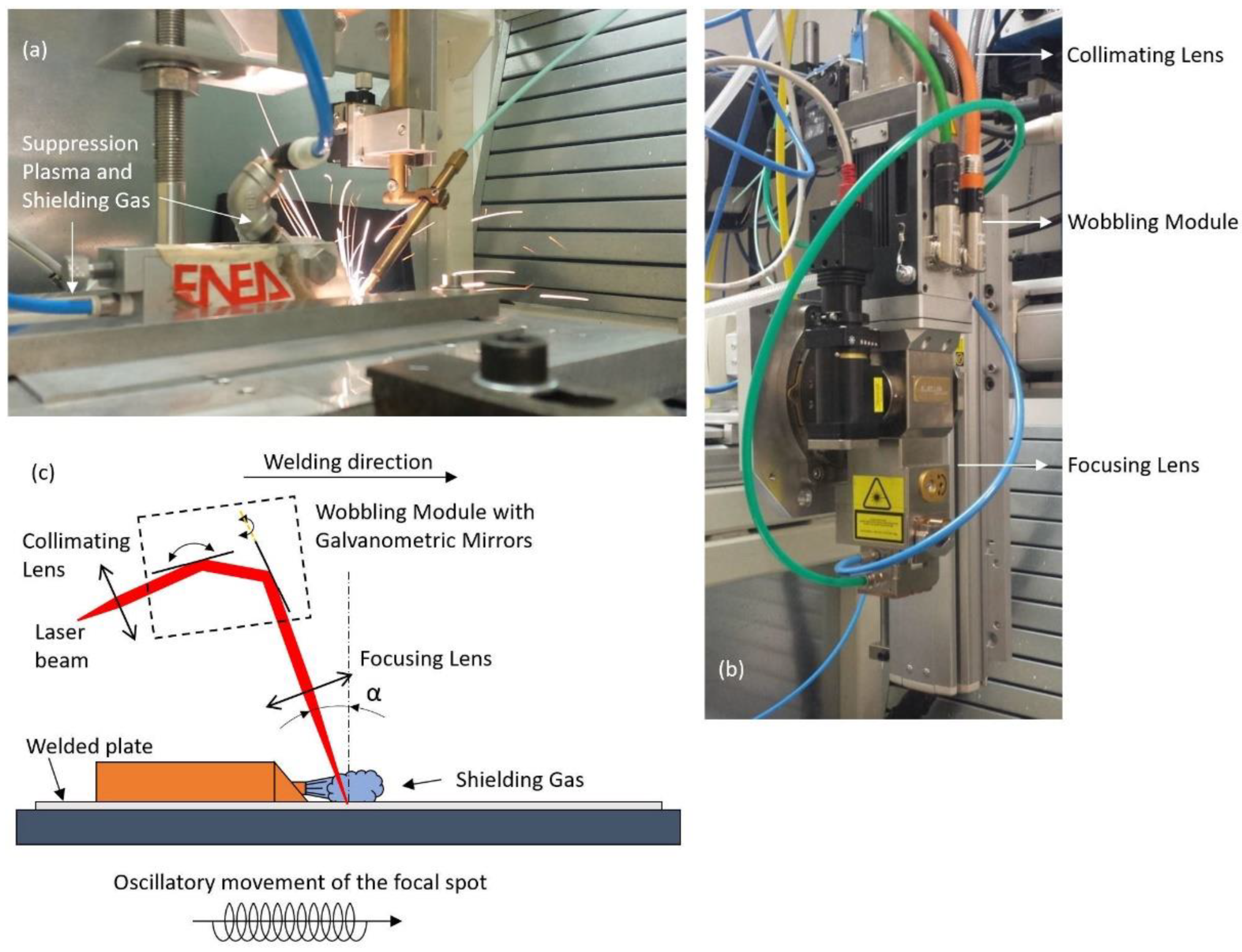
Figure 1. (a) Welding setup; (b) welding head; (c) working principle diagram.
Metals 12 02039 g001
Figure 2. Schematic illustration of the welded plates. XRD measurement locations are indicated by crosses, while the two cuts used for the contour method are displayed by dotted lines. All dimensions are in mm.
Metals 12 02039 g002
Figure 3. Surface contour measurement using fringe projection.
Metals 12 02039 g003
Figure 4. Surface longitudinal residual stresses measured by X-ray diffraction (stresses are in MPa).
Metals 12 02039 g004
Figure 5. Surface transverse residual stresses measured by X-ray diffraction (stresses are in MPa).
Metals 12 02039 g005
Figure 6. Surface profile of (a) the first cut, (b) the second cut side A (Inconel 625 side), and (c) the second cut side B (Ti6Al4V side), after cubic spline smoothing.
Metals 12 02039 g006
Figure 7. Longitudinal residual stress map (stresses are in MPa).
Metals 12 02039 g007
Figure 8. Transverse residual stress map in Vanadium insert using multiple cuts, asymmetric stiffness analysis, and superposition principle (stresses are in MPa).
Metals 12 02039 g008
Figure 9. Temperature map during a fatigue test: (a) stabilized temperature at 30% of the fatigue life; (b) prior to fracture; (c) at fracture.
Metals 12 02039 g009
Figure 10. S-N curve of Ti6Al4V—Inconel 625 joints, reprinted from [43] with permission from Elsevier, 2022 year.
Metals 12 02039 g010
Figure 11. Surface topography of the specimens tested at Δσ = 200 MPa: (a) Failure at 440,740 cycles (specimen 6); (b) failure at 192,951 cycles (specimen 7).
Metals 12 02039 g011
Figure 12. Fracture surfaces of the specimens tested at Δσ = 200 MPa: (a) Failure at 440,740 cycles (specimen 6); (b) failure at 192,951 cycles (specimen 7).
Metals 12 02039 g012
Figure 13. EDS of the specimen tested at Δσ = 200 MPa and failed at 192,951 cycles (specimen 7).
Metals 12 02039 g013
Figure 14. Fracture surface of the specimen tested at Δσ = 220 MPa and failed at 67,000 cycles (specimen 8): (a) Fractographies and (b) EDS spectra with the indication of the analyzed points.
Metals 12 02039 g014
Figure 15. Fracture surface and EDS of the specimen tested at Δσ = 220 MPa and failed at 149,345 cycles (specimen 9).
Metals 12 02039 g015
Figure 16. Fracture surface of the specimen tested at Δσ = 170 MPa and failed at 1,148,109 cycles (specimen 3).
Metals 12 02039 g016
Figure 17. EDS of the specimen tested at Δσ = 170 MPa and failed at 1,148,109 cycles (specimen 3). The arrows indicate the analyzed points.
Metals 12 02039 g017
Figure 18. EDS maps of the specimen tested at Δσ = 140 MPa and runout (specimen 1).
Metals 12 02039 g018
Table 1. Nominal chemical compositions (wt%) of Ti6Al4V, Vanadium, and Inconel 625. Chemical composition (wt%) with percentage error of AISI 304 measured by XRF.
ElementsTi6Al4VVanadiumAISI 304Inconel 625
Al5.5–6.8--≤0.40
C---≤0.10
Co---≤1.0
Cr--19.96 ± 0.27%20.0–23.0
Cu--0.7 ± 2.79%-
Fe≤0.30-71.13 ± 0.18%≤5.0
H≤0.015---
Mo--0.27 ± 2.36%8.0–10.0
Mn---≤ 0.50
N≤0.05---
Nb---3.15–4.15
Ni--7.82 ± 0.66%≥58.0
O≤0.20---
Si---≤0.50
TiBalance-0.12 ± 2.05%≤0.40
V3.5–4.5≥99.9--
Table 2. Mechanical properties of the materials composing the welded plate [42,43].
Materialsσy [MPa]σu [MPa]E [GPa]vɛu %
Ti6Al4V880950125.50.3610
Vanadium439472120.20.3627
AISI 3042155151960.2870
Inconel 6254608802080.2845
Table 3. X-ray diffraction measurement parameters.
MaterialTubeExposure Time (s)No. of TiltsTilt Angle (°)Psi OscillationCollimator Diameter (mm)Voltage (kV)Current (mA)
Inconel 625Cr354±45±31308.0
AISI 304Cr604±45±01308.0
Ti6Al4VTi404±40±01307.5
Table 4. Knot spacings of the cross sections’ largest dimension and average stress uncertainties for the first and second cut. Side A corresponds to the Inconel 625 side of the cut part, while side B is the Ti6Al4V side.
CutsKnot Spacing [mm]Average Stress Uncertainty [MPa]
First Cut18.7232.05
Second Cut Side A15.8278.10
Second Cut Side B14.3212.22
Second Cut Average-35.92
Table 5. Coefficient of thermal expansion of the materials composing the welded plates [42,43].
PropertyInconel 625AISI 304VanadiumTi6Al4V
CTE [µm/m K−1]12.817.38.39.0
Table 6. Parameters and results obtained from fatigue tests, reprinted from [43] with permission from Elsevier.
SpecimenΔσ [MPa]Number of Cycles to FailureZone of Fracture
11405,000,000Runout
21605,000,000Runout
31701,148,109V-SS
41801,011,176Ti-V
51802,885,345Ti-V
6200440,740Ti-V
7200192,951V-SS
822067,000Ti-V
9220149,345V-SS
Table 7. Surface parameters calculated by topographical analysis of specimens 6 and 7.
SpecimenΔσ
[MPa]
NfractureFracture ZoneSq
[μm]
SskSkuSp
[μm]
Sv
[μm]
Sz
[μm]
Sa
[μm]
6200440,740Ti-V48.540.112.45127.63102.33229.9739.72
7200192,951V-SS49.80−0.151.98101.60136.25237.8542.87
Table 8. Fracture details for specimens 8 and 9.
Specimen Δσ [MPa]NfractureFracture ZoneFracture Mode
822067,000Ti-Vductile (striations)
9220149,345V-SSbrittle (micro-cleavage)
Table 9. Summary of fracture modes.
Specimen Δσ
[MPa]
NfractureFracture ZoneFracture Mode
11405,000,000runout-
21605,000,000runout-
31701,148,109V-SSmixed (PSB, micro-voids coalescence, micro-cleavage)
41801,011,176Ti-Vductile (striations)
51802,885,345Ti-Vductile (striations)
6200440,740Ti-Vbrittle and flat (affected by voids, does not change fracture interface but fracture mode and fatigue life)
7200192,951V-SSbrittle (micro-cleavage)
822067,000Ti-Vductile (striations)
9220149,345V-SSbrittle (micro-cleavage)
Publisher’s Note: MDPI stays neutral with regard to jurisdictional claims in published maps and institutional affiliations.