Article

Process Stability and Material Properties of TC4 Alloy Welded by Bypass Current Hot Wire Plasma Arc Welding (BC-PAW)

National Key Laboratory of Science and Technology on Underwater Vehicle, Harbin Engineering University, Harbin 150001, China
*
Author to whom correspondence should be addressed.
Metals 2022, 12(11), 1949; https://doi.org/10.3390/met12111949
Submission received: 24 August 2022 / Revised: 25 October 2022 / Accepted: 8 November 2022 / Published: 14 November 2022
(This article belongs to the Section Metal Casting, Forming and Heat Treatment)

Abstract

:
To improve welding efficiency, bypass current hot wire plasma arc welding (BC-PAW) was employed to weld Ti-6Al-4V alloy. The influence of process variables on metal transfer behaviour was explored using high-speed camera, and the material properties were investigated by means of different microscopes and mechanical test. The result shows that the weld seam has a good surface finish without welding defects. The main current, bypass current, and wire feeding speed have a significant influence on the metal transfer behaviour, which further influence the grains’ formation in the weld zone. The microstructure of the weld mainly comprises α martensite and the average tensile strength (UTS) of the as-received joint is 986 MPa, which is larger than that obtained using the conventional PAW method. The fracture occurs in the heat-affected zone (HAZ), which shows a typical ductile fracture surface.

1. Introduction

Recently, in the shipbuilding industry, Ti6Al4V (TC4) alloy has attracted significant research interest for the manufacturing of important components, thanks to it having some excellent properties [1], including low density, good corrosion, and high temperature resistance properties, among others. Welding is the most frequent method of connecting metals. Many welding methods, such as MIG (metal inert gas arc welding) [2], TIG (tungsten inert gas arc welding) [3], PAW (plasma arc welding) [4], and laser [5], have been successfully applied to the welding of titanium alloys in actual production.
The traditional titanium alloy welding technology is argon arc welding technology and laser welding technology. Arc welding is more convenient in operation and observation. It has a wide range of applicable materials, but there are large welding heat-affected zones, large welding stress, and large post-weld deformation. Laser self-fusion welding is a relatively common laser welding method, but it is very easy to form a depression on the surface of the weld and cause problems such as penetration, which cannot meet the higher accuracy requirements [6]. There are also some defects such as low welding efficiency and weak penetration ability [7]. Thence, when welding thick titanium alloy plates, it is necessary to make large grooves and perform multi-layer and multi-pass welding in spite of increasing the welding cost [8]. The plasma arc is condensed so that we can obtain concentrated energy, stronger straightness, and better penetration ability [9]. The maximum thickness of the disposable weld is 10–12 mm [10], whereas, in the case of wire filling, the melting efficiency of the welding wire is relatively low. If the wire feeding speed is blindly increased, the blocking of the welding wire will weaken the penetration ability of the plasma arc [11]. This will mean that the traditional wire-filled plasma arc welding cannot take into account the penetration ability and the deposition efficiency simultaneously [12]. In the field of medium-thick plate TC4 welding, PAW demonstrates clear advantages, such as high energy density and high flexibility, while being less expensive than laser welding [13]. PAW often requires filler metals to meet the demands of different working conditions. Furthermore, the welding wire needs to be heated in order to increase the cladding mount. However, the conventional hot wire method tends to increase the welding energy and thus be detrimental to the joint quality.
In this work, bypass-current hot wire plasma arc welding (BC-PAW) was used to weld Ti6Al4V alloy. This method can not only increase the cladding, but also reduce the heat input to the substrate. To better understand the essential characteristics of this method in TC4 welding, the process stability was explored to reveal the welding mechanism and the material properties were investigated to reveal the strengthening effect of the weld. This research contributes to improving the strength of welded joints in titanium alloys and offers more possibilities for energy control in the PAW process.

2. Materials and Methods

The apparatus consists of a BC-500AD PAW power source, hot wire feeder, water cooling unit, and travel mechanism, as shown in Figure 1. Ti6Al4V wire with a diameter of 1.2 mm was used to weld Ti6Al4V substrate with dimensions of 100 mm × 50 mm × 8 mm, which conforms to the ASTM B265 specification. The chemical compositions of the base material and wire are shown in Table 1.
The principle of the method is shown in Figure 1. This method works by adding the path of bypass current to separate part of the welding current, which flows through the plasma tungsten electrode to form a bypass current, namely I p , and the remaining current part I m flows through the base metal.
I = I p + I m
This method has two advantages: on the one hand, the welding current through the base metal is reduced and, subsequently, the heat input to the base metal is decreased. It is beneficial to the stability of the welding arc and to reduce the deformation of the base metal. Moreover, it prevents the coarse grains from causing the decrease in the joint mechanical performance. On the other hand, the bypass current flows through the welding wire, which can generate resistance heat to hot wire and then helps to improve the melting efficiency of the wire. The welding process parameters are shown in Table 2.
Both metallographic specimens and mechanical test samples were extracted from the weld for further investigation. The metallographic specimens were hot mounted, ground and polished according to standard procedures, and then etched in Kroll’s reagent (2% vol HF, 6% vol HNO3 with balance H2O). The microstructures were examined using a OLYPUS-SZX12 microscope (Olypus Corporation, Massachusetts, USA, North America) and the microstructures were observed using VHX-1000E optical microscope-OM (Keyence, Kallang Avenue, Singapore, Asia). Vickers hardness testing was performed with HXD-1000TMC hardness tester (CANY, Shanghai, China, Asia) with load of 200gf, dwell time of 15s and the distance between every 2 test points is 0.3mm. Tensile tests were performed on Zwick/Roell Z010 (ZwickRoell, Germany, Europe) at room temperature at a constant cross head displacement rate of 0.4 mm/min. Fracture surface was observed on QUANTA200-SEM (FEI NanoPorts, Oregon, USA, North America).

3. Results and Discussion

3.1. Droplet Transfer Behaviors

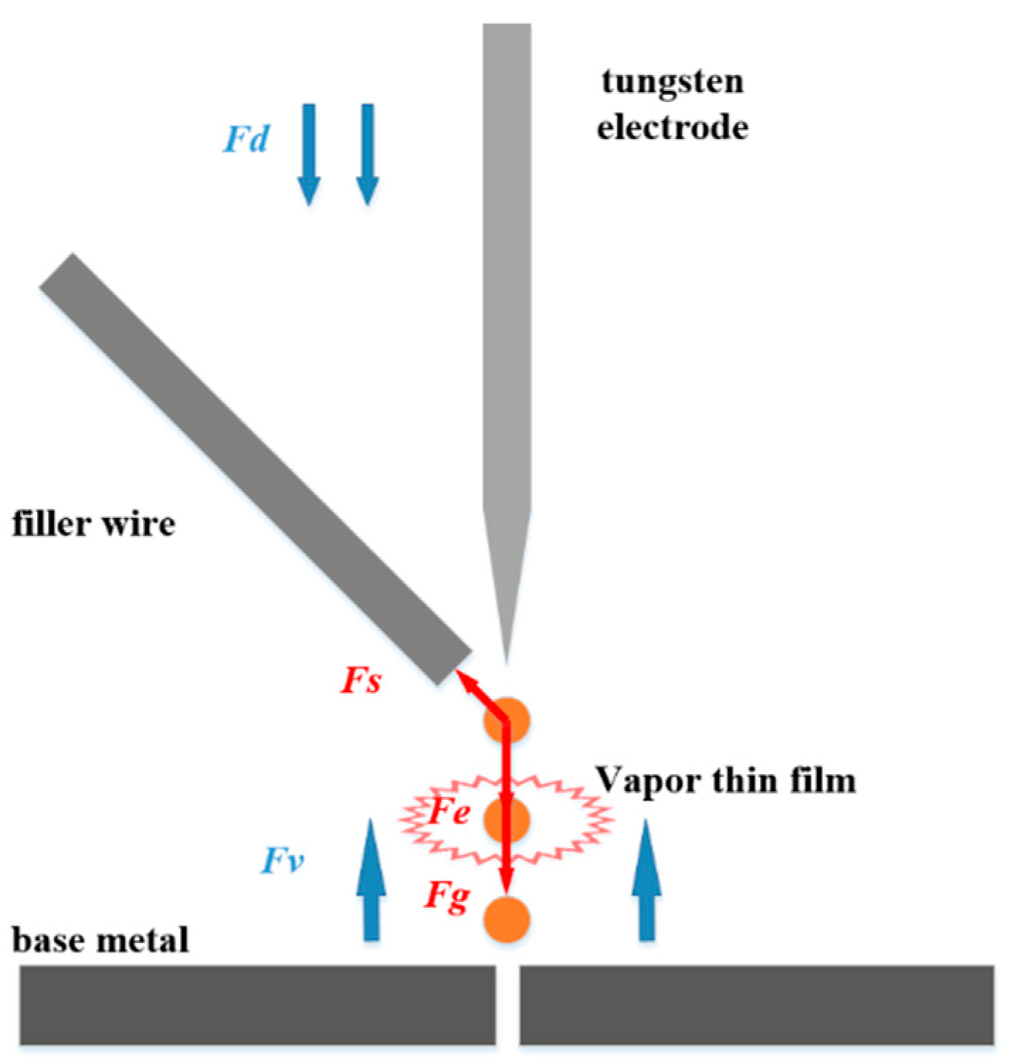
In the welding process, the droplet transfer behaviors have an significant influence on the process stability and weld formation. Smooth droplet transfer often delivers more stability and less spatter. In this study, by changing the wire height, main current, and bypass current, the influence of these parameters on the droplet transfer form, transfer frequency, and droplet size of the bypass hot wire plasma arc is studied. The influence of various parameters on the form of droplet transfer will be discussed below. The effects of process variables on metal transfer behaviors, including droplet size and its transfer mode and frequency, will be discussed during BC-PAW. The droplets can be identified as a certain type by the union of gravitational force ( F g ), drag force ( F d ), surface tension force ( F s ), electromagnetic force ( F e ) , and vapor jet force ( F v ). It is given by
F g + F d + F e = F s + F v
It is shown in the Figure 2 that it consists of the relationship of five kinds of forces on the molten droplets.
In the formula above, F g is the gravitational force, which is generated by the density of the wire material ( ρ ), acceleration of gravity (g), volume (V), and mass of the droplet (m). It shows a major function in globular transfer by promoting the droplet to enter the molten pool. It is given by
F g = m g = ρ V g
where F d is drag (aerodynamic) force due to the flow of gas around the droplet. It helps detach the droplet from the electrode tip and depends on the amount of gas flow in BC. F d is affected by the gas velocity (v), density of shielding gas ( ρ ), droplet radius (r), and drag coefficient ( C d ). It is given by
F d = 1 2 π v 2 ρ r 2 C d
where F e is electromagnetic force generated due to the magnetic field and welding current. It is hardly of any consequence on the solid electrode, but results in a considerable influence on the detachment of the droplet from the electrode and is referred to as the Lorentz force or electromagnetic pinch force. It depends on the magnetic permeability, current in conductor, and radius of the current path ( r or R ). It is given by
F e = 100 μ I 2 8 π 2 R 2 2 r 2 R 2
where F s is surface tension force, which tends to retain the droplets at the tip of the electrode and its magnitude at the time of droplet detachment under its own weight. It depends on the constant of capillarity of the electrode material (c), mass of the droplet ( m ), density of the droplet material ( ρ ), surface tension ( γ ), and electrode radius (r), and it is given by
F s = 2 π γ r · f r c
c 2 = 2 γ m g ρ
The metal-vapor jet force F v is a function of the surface temperature of the droplet. It depends on the total mass vaporized per second per ampere ( m o ), vapor density ( d v ), welding current (I), and current density (J). It is given by
F v = m o d v · I · J
In this study, because of the high heat input of the plasma arc, we will mainly discuss how the surface tension force and vapor jet force affect the metal transfer. By changing the specific parameter based on the formulas above, better metal transfer can be obtained, which is spray transfer. It will be discussed below on two prospects: the distance between wire tips and the work pieces, and the hot wire bypass current.

3.1.1. The Effects of the Distance between Wire Tips and the Work Piece on Droplet Transfer

Figure 3 shows that short-circuit transfer occurs when the distance between the wire tips and work piece is 1 mm. The droplets come into contact with the melt pool and the forces of droplet–wire and droplet–pool counteract each other. The droplet forms a metal liquid bridge that prevents the formation of globular transfer. Instead, the cross section of the droplets shrinks, which reduces the surface area. The surface area directly affects the surface tension force, vapor jet force, and heat loss of the droplets. The droplet flows into the melt pool steadily along the bridge. Thus, it can be in a stable state during the metal transfer process. However, it has some disadvantages that consist of lack-of-fusion, high spatter, and cold lap due to low heat input and low amperages.
Figure 4 shows that, when the distance between the wire and the base metal is increased to 5 mm, the form of metal transfer is globular transfer, which can maintain a good transfer efficiency. When the distance between the filler wire and the base metal is 8 mm or more, the metal transfer form is free transfer with a low efficiency. As the change in distance just obtained short-current and globular transfer, it can be known that distance cannot be the critical factor of transfer form. During parameter adjustment, it should be controlled in an appropriate distance range.

3.1.2. The Effect of Bypass Plasma Arc Current

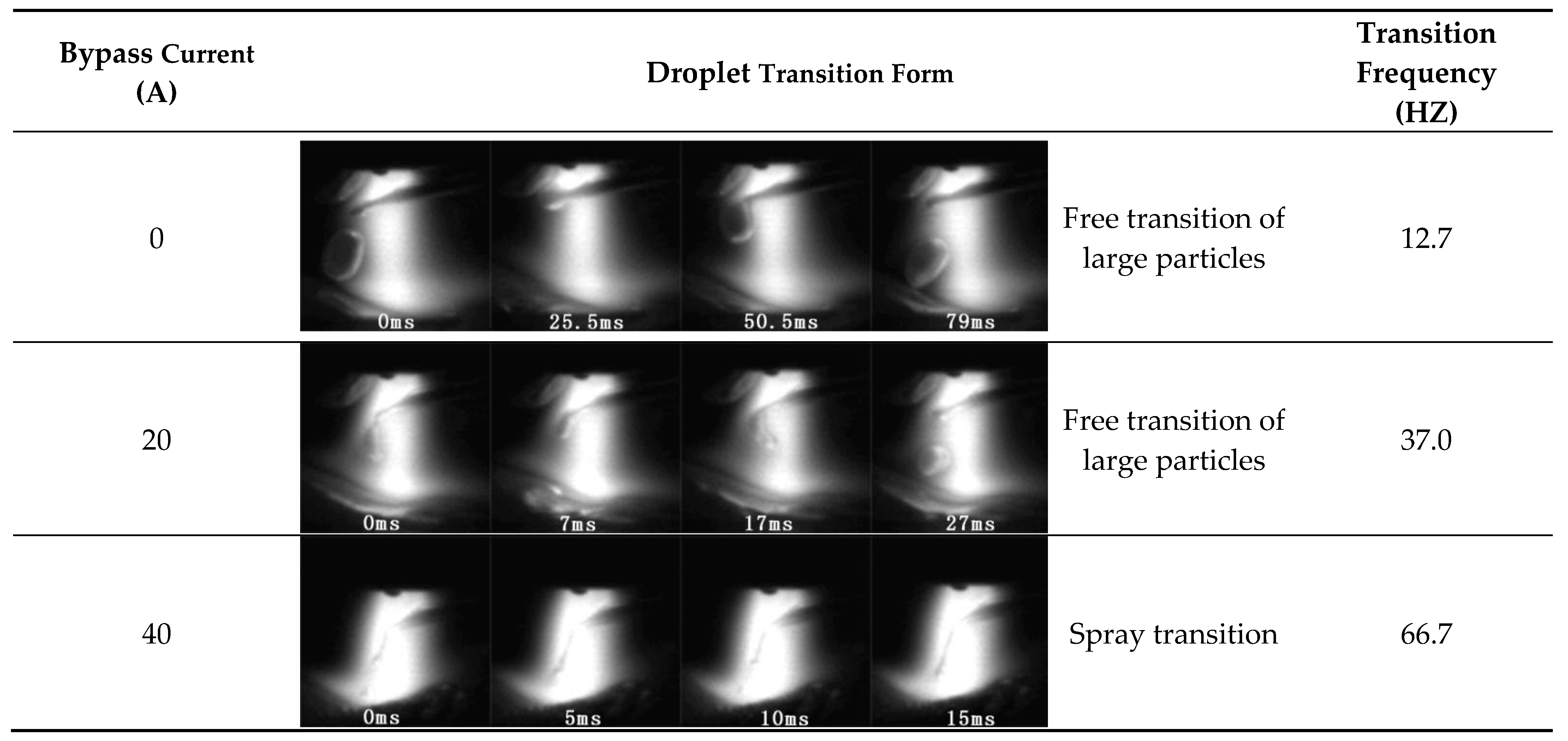
Figure 5 shows that this experiment presents the bypass current. The main current is small and its value is from 140 to 160 A. When the total welding current is stable, part of the plasma arc current flows through the welding wire. Consequently, it reduces the current flowing through the base metal and the heat input of the base metal. When the bypass current is not applied, the transition form of the droplet is free transition. The faster feeding speed makes the wire pass through the arc. The position of the welding wire is behind the arc. The droplet size is larger and the transition frequency is low. In the form of droplet transfer, the droplets directly smash into the melt pool, resulting in violent oscillation of the melt pool and the instability of the pool, leading to poor weld formation. The positional relationship between the plasma arc and the filler wire is not good, which weakens the penetration ability of the plasma arc and reduces the welding efficiency. The bypass current that flows through the wire has an effect as a hot wire. The melting efficiency of the welding wire is increased and the adjustable range of the wire feeding speed is increased. Similarly, the main arc and the bypass arc are coupled with each other and the droplet transfer form is improved.
When the bypass current is set to 20 A, the transfer form is free transfer, the size of the droplet decreases, and the transition frequency increases. When the bypass current is increased to 40 A, it changes to droplet transfer. At this time, the current flowing through the welding wire is increased to 40 A; the effect of the bypass current is more obvious; the melting efficiency of the welding wire is increased; and the wire feeding speed, the bypass current, and the plasma arc current are reasonably matched. Under the action of plasma flow force, gravity, surface tension, and so on, at the end of the welding wire, a small liquid flow transitions to the molten pool. The molten pool is in a stable state, which is conducive to the formation of beautiful and high-quality weld joints.
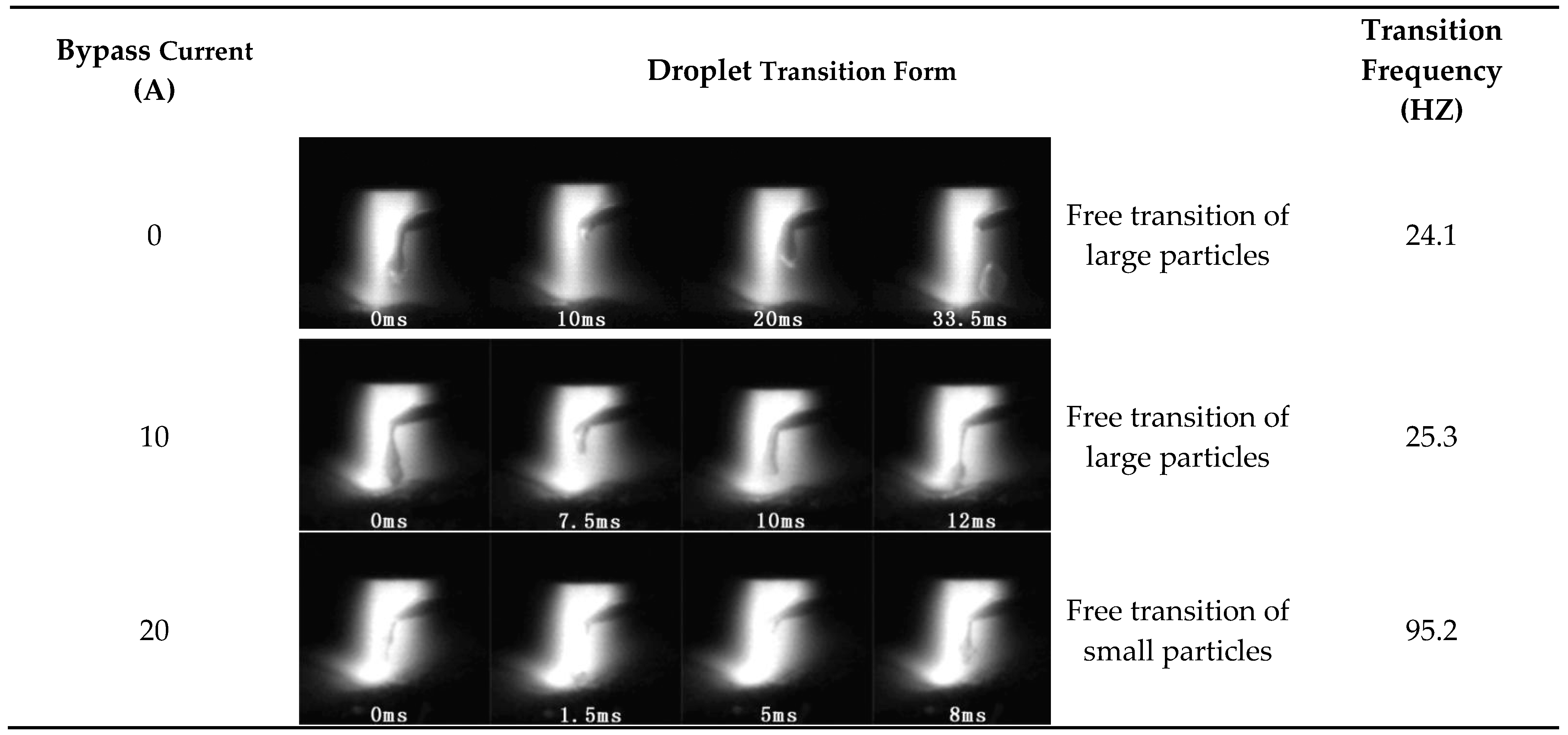
Figure 6 shows the droplet transfer of different small bypass current. The main circuit plasma current used in the test is 270–300 A and the wire feeding speed is relatively low. In the case of high current, the faster wire feeding speed will lead to the loss of plasma arc heat and the decrease in penetration ability. At this time, when the bypass current is not applied, the welding wire melts at the edge of the plasma arc, and the low wire feeding speed makes the droplet transfer form between the large droplet contact and the large droplet free modes. The diameter of the droplet is slightly larger than that of the welding wire. The transition frequency is low and the droplet is prone to deflection, and the melt pool is unstable. When the applied bypass current is 10 A, it has a preheating effect on the welding wire. The viscosity coefficient and surface tension coefficient of the welding wire decrease, the welding wire is more likely to drip, the droplet diameter decreases, and the transition frequency increases. When the bypass current is increased to 20 A, the droplet transfer form is a droplet free transfer (droplet transfer). At this time, the droplet transfer form is stable and the weld seam is beautifully formed. In addition, when the bypass continues to increase, the penetration ability of the plasma arc is significantly weakened owing to the decrease in the current flowing through the base material, and the phenomenon of incomplete penetration appears.

3.2. Microstructure

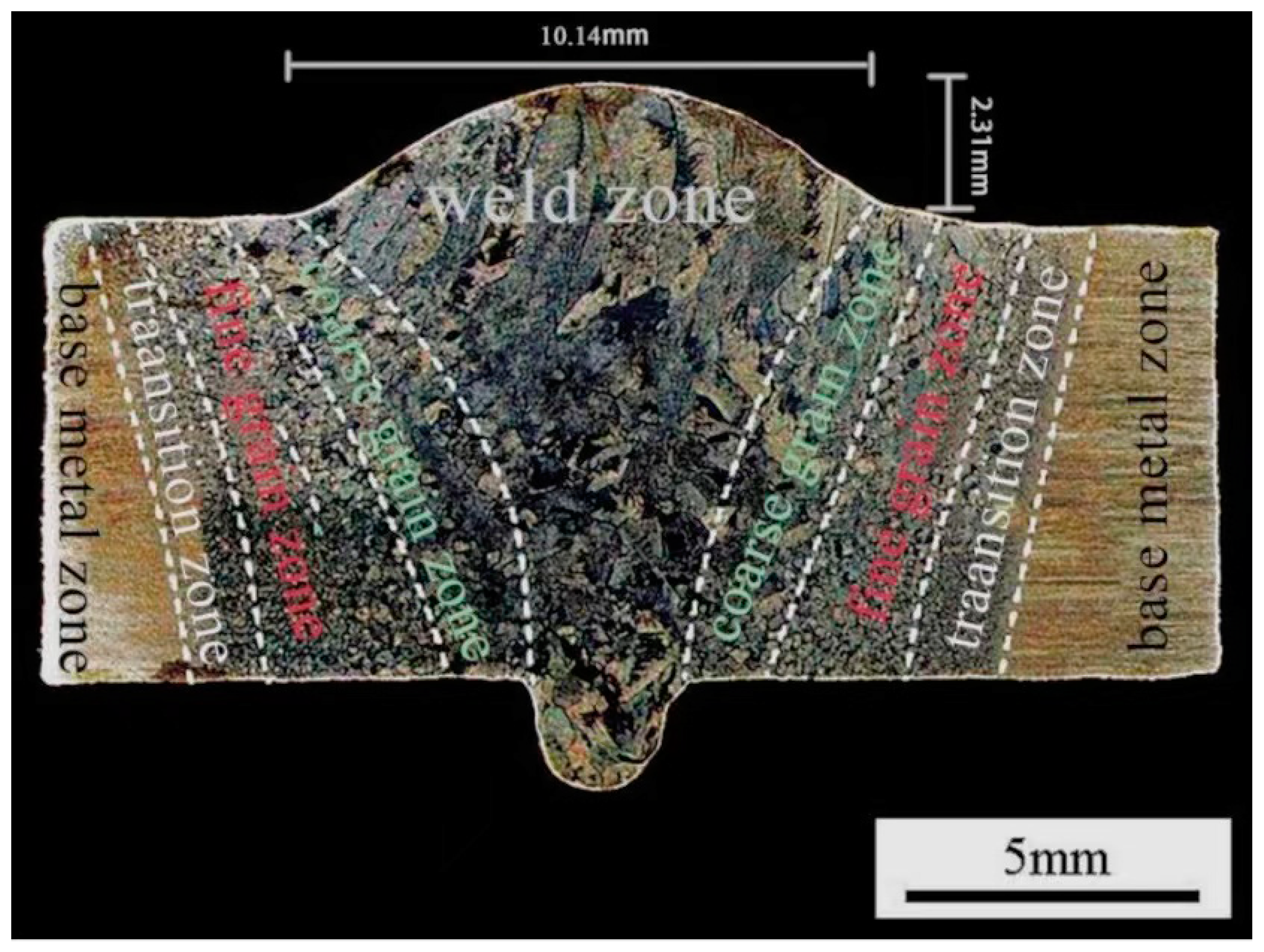
Figure 7 shows a cross-sectional view of the obtained butt joint from the weld to the base metal followed by the weld zone, heat-affected weld zone, heat-affected coarse grain zone, heat-affected fine grain zone, transition zone, and base metal zone.
Figure 8 shows the shape of the weld bead. Through the analysis of droplet transfer above, setting the bypass current to 40 A can obtain a well-shaped weld. The reinforcement of the front weld is 2.31 mm and the width of the weld is 10.14 mm. It shows fish scales on the surface. The reinforcement of the reverse side is 1.89 mm and the width of the weld is 2.73 mm, with a uniform forming. They are fused together to achieve a single-sided and double formed welding surface. There are no splashes on the surface during the process of welding. Similarly, the uniform brightness of the titanium alloy is on both sides of the welding seam welding process. It verifies that the hot wire arc welding process can achieve the valid welding of 8 mm TC4 alloy.

3.3. Microstructure Morphology

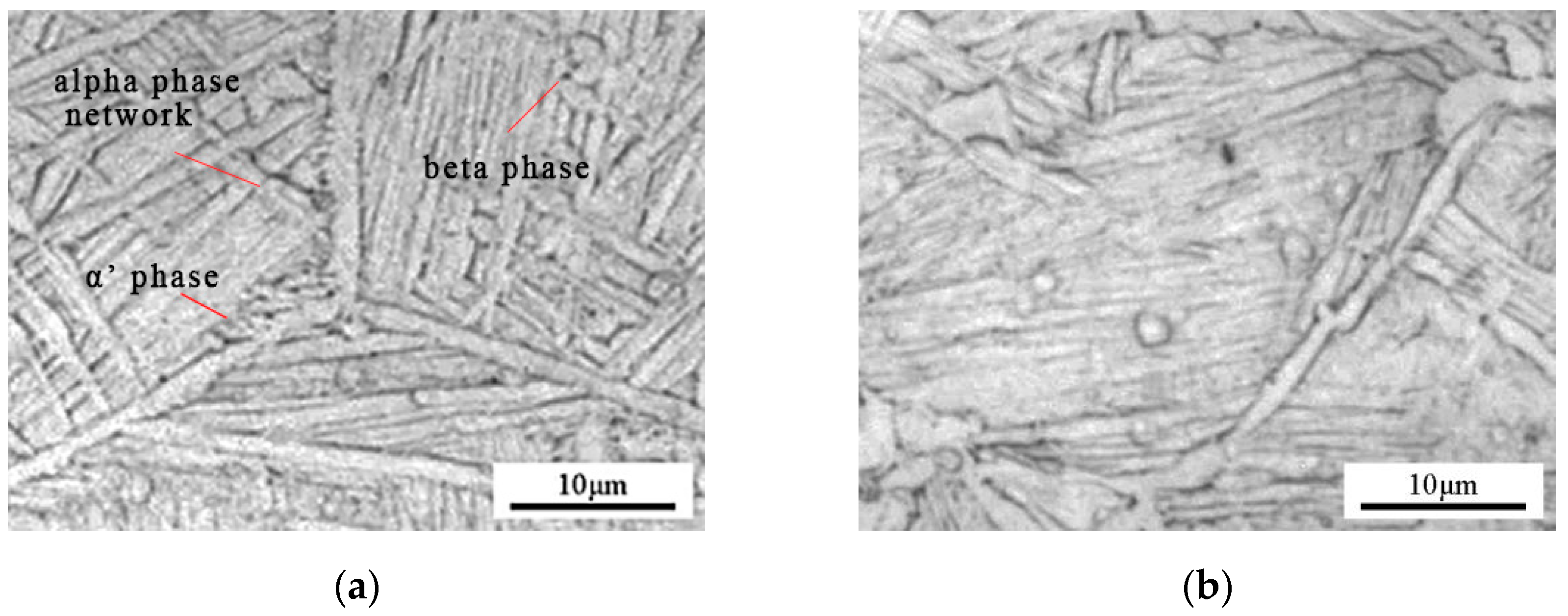
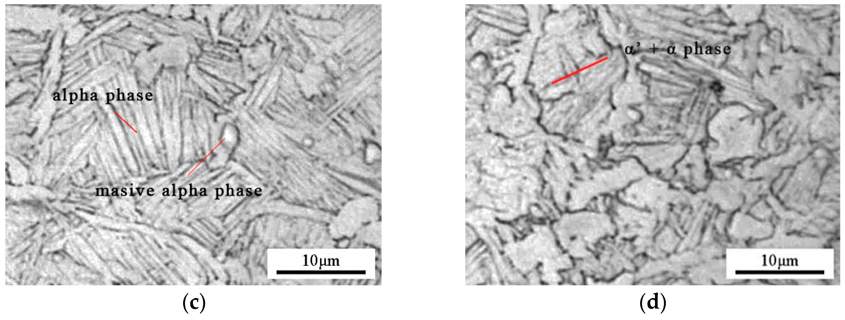
Figure 9 shows the microstructure of each characteristic zone of the joint. The metallographic sample is cut at the middle position on the titanium alloy sample. It is obvious that the microstructure of the weld area is mainly composed of   α   martensite. This is because of the large degree of under-cooling of the molten pool during the gradual cooling process [14]. Simultaneously, the transformation from β phase to α phase occurs inside the coarse grain zone. Then, the nucleation of the martensite phase begins and it is grown perpendicularly to the grain boundary due to the rapid cooling process, so that it forms a uniform arrangement of the beam martensite basket-shaped tissue structure. Because of the fact that the thermal action of the radial crystal zone is less than the weld zone and the time is ephemeral above the β phase change temperature, the thermal action affects the equisum β of the crude crystal zone. The size of the grain is much smaller than the weld zone. Similarly, the cooling rate of the heat-affected coarse-grained zone is faster than the weld zone, the thickness of the alpha phase grain boundary formed is smaller, and the beam-shaped martensite growth distance is shortened. Heat-affected fine grain zone whose temperature just reaches the temperature of the α phase to the β phase, which is far from the weld zone, so that the heat-affected fine grain zone in the β phase area is shorter and the growth of the β phase is restricted. It will form relatively small equiaxed β grains after cooling, which is completed in a very short time [15]. The growth of the martensite is not obvious and the size is small. The transition zone is far from the plasma arc heat source center. The temperature peak is located in the α + β dual phase interval, so that only a small amount of α in the transition zone is converted into β phase, the growth of the β phase is limited, and it is difficult to have a certain size. During the cooling process, these smaller β grains are converted to α martensite and the fine α martensite formation of α + α interlaced distribution.

3.4. Mechanical Properties

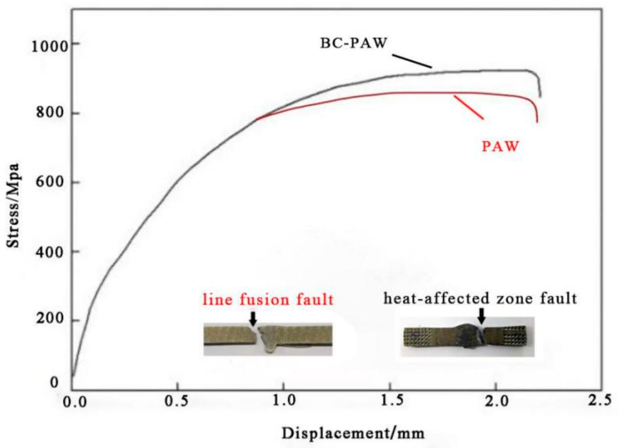
Figure 10 shows the displacement–stress curve of the joint by BC-PAW with and without a hot wire. The tensile strength of the hot wire BCPAW-welded joint is 964 MPa, which is about 98% of the as-reviewed titanium alloy base material, and the fracture occurs at the heat-affected zone. The tensile strength of the BCPAW-welded joint is 928 MPa, and the fracture occurs at the fusion line area. This means that the hot wire during BC-PAW process benefits lead to the improvement in TC4 joint strength.
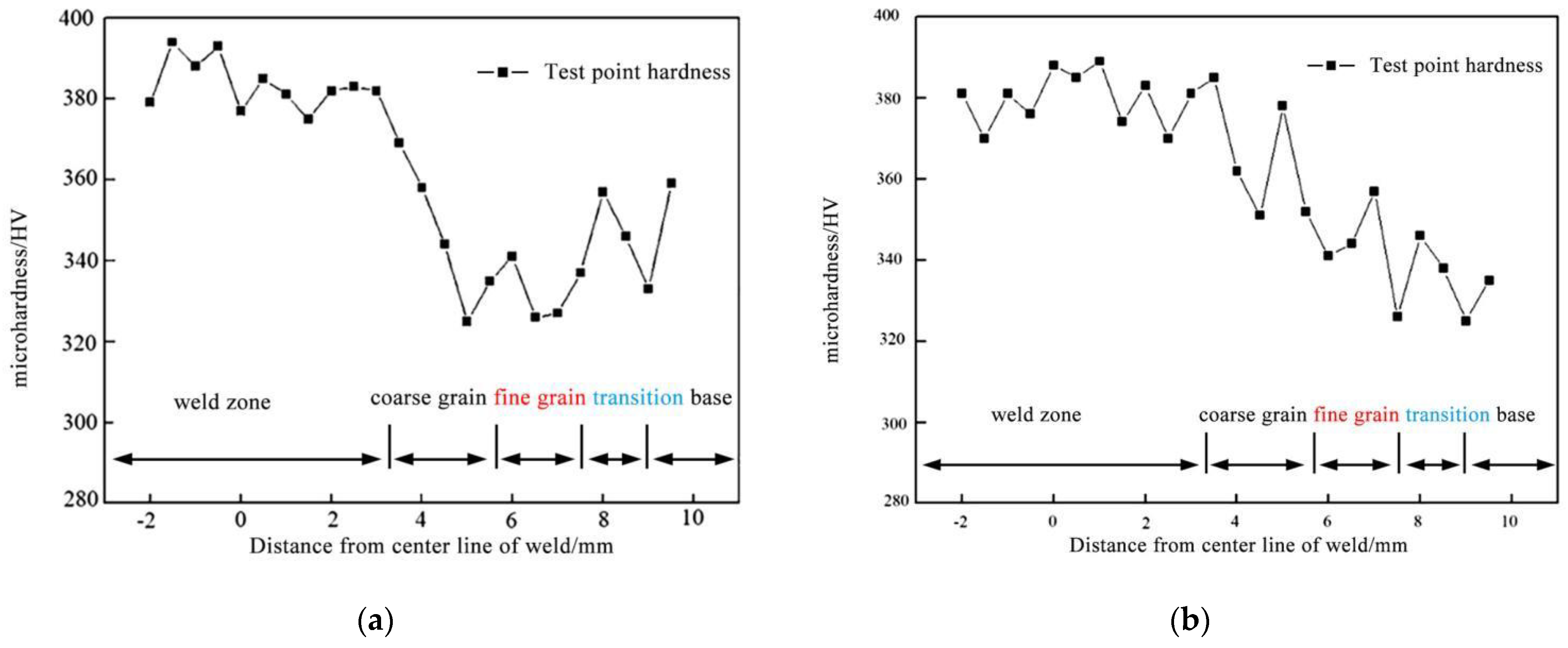
Figure 11a shows the hardness distribution of the joint using hot wire BC-PAW. It can be seen that the hardness value of the weld area is the largest, which is about 15% higher than the base metal zone. Moreover, the hardness value of the heat-affected area shows a gradual decrease from the weld zone to base metal. Figure 11b shows the hardness distribution of joint welded by BC-PAW without a hot wire, and it can be seen that the heat-affected zone has an obvious softening phenomenon [16]. The hardness of the coarse grain zone and the fine grain zone is reduced, and the zone where softening occurs is large. This leads to a decrease in its strength. During the BCPAW with a hot wire process, the heat input into based metal was decreased owing to the part of welding current flowing into the welding wire. This impedes the grin growth and leads to a narrow HAZ generation. Meanwhile, the welding wire melting efficiency is improved by generating resistance heat and the remaining current flowing through the base material is reduced. This reduces the heat input to the base metal. Without reducing the penetration capacity of the plasma arc, it prevents the excessive growth of crystal grains in order to be conducive to achieving the uniformity of the structure. Thence, there is no obvious mutation in the micro-hardness of the joint.

3.5. Fracture Morphology

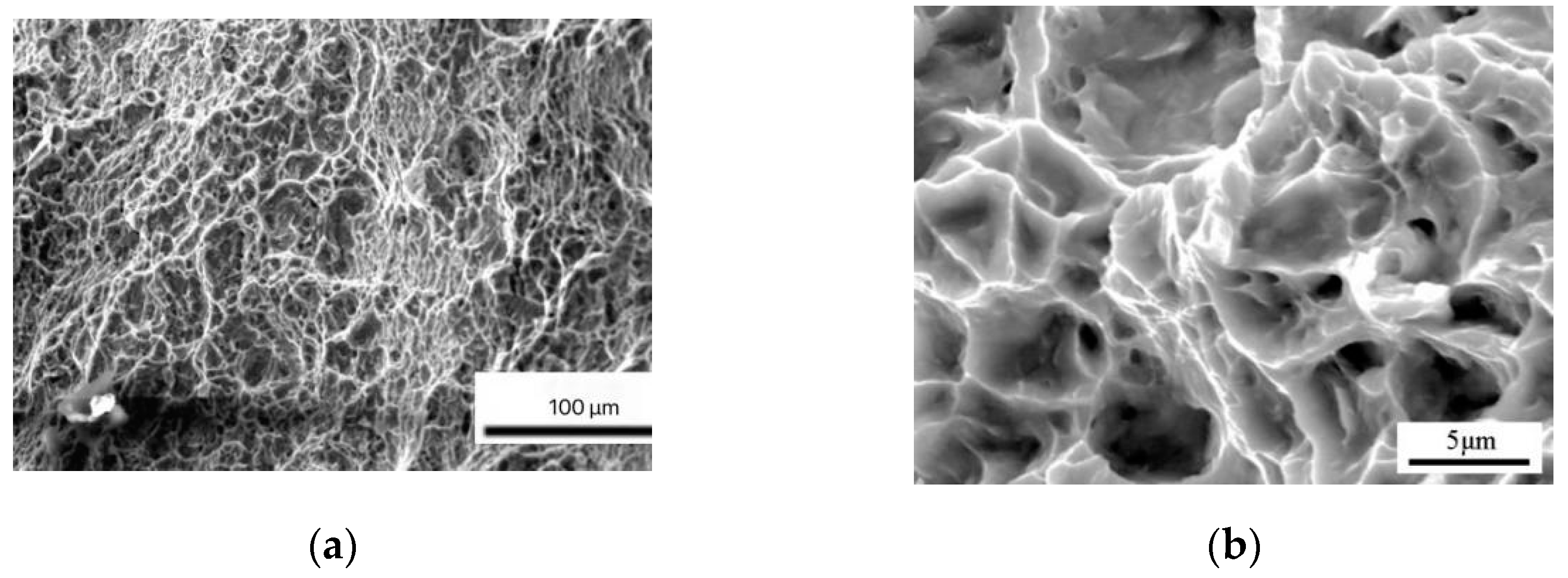
Figure 12 displays the photographs of the tested tensile samples. Both of the samples present ductile morphology with a large number of shallow and stretched dimples in response to fracture. There is no significant difference in the fracture features in the samples that have been produced with and without a hot wire. However, the fracture surface of the specimen welded with BC-PAW using a hot wire presents slightly larger dimples, which demonstrates that the grains in this area are mostly equiaxed grains with smaller size, slightly poorer strength, and good toughness [17]. The fracture position of the traditional wire-filled plasma arc welding joint is in the fusion line or weld zone and there is also a large number of dimples. The dimples’ depth is slightly smaller than that of the former, while the grain size in this area is larger and the toughness is slightly worse. The results show that the joint welded by BC-PAW has good strength and toughness.

4. Conclusions

In this work, TC4 alloy was welded by bypass current hot wire plasma arc welding (BC-PAW) and the process stability and material properties were explored and discussed. The findings include the following:
  • BC-PAW significantly promotes welding efficiency through a rapid increase in wire melting during the welding. A hot wire using bypass current is easily implemented and is beneficial to welded TC4 components, contributing to an appealing surface finish with improved hardness and enhanced strength.
  • Through the microstructure analysis, the weld zone has the largest grains, whose growth direction tends to the center of arc. The heat-affected zone has the small grains, with regular and fine equiaxed crystals.
  • The average tensile strength of the BC-PAW TC4 joint is 986 MPa, which is about 98% of the base metal. The fracture occurs in the heat-affected zone, showing ductile fracture morphology. It is found that the mechanical strength of the TC4 alloy weld can be improved by BC-PAW welding with a hot wire.

Author Contributions

Study design, data analysis, Y.M.; literature search, data collection, data analysis, writing, Y.W.; analogue simulation, data collection, Z.W.; data collection, Y.Z.; data analysis, C.L.; literature search, J.L. All authors have read and agreed to the published version of the manuscript.

Funding

This research received no external funding.

Data Availability Statement

Data presented in this article are available upon request from the corresponding author.

Conflicts of Interest

The authors declare no conflict of interest.

References

  1. Xu, W.; Zhao, Y.; Chen, X.; Zhong, B.; Yu, H.; He, Y.; Tao, C. An Ultra-High Frequency Vibration-Based Fatigue Test and Its Comparative Study of a Titanium Alloy in the VHCF Regime. Metals 2020, 10, 1415. [Google Scholar] [CrossRef]
  2. Kaseem, M.; Choe, H.-C. Acceleration of Bone Formation and Adhesion Ability on Dental Implant Surface via Plasma Electrolytic Oxidation in a Solution Containing Bone Ions. Metals 2021, 11, 106. [Google Scholar] [CrossRef]
  3. Wang, L.; Chen, J.; Wu, C. Auxiliary energy-assisted arc welding processes and their modelling, sensing and control. Sci. Technol. Weld. Join. 2021, 26, 389–411. [Google Scholar] [CrossRef]
  4. Czuprynski, A. Microstructure and Abrasive Wear Resistance of Metal Matrix Composite Coatings Deposited on Steel Grade AISI 4715 by Powder Plasma Transferred Arc Welding Part 1. Mechanical and Structural Properties of a Cobalt-Based Alloy Surface Layer Reinforced with Particles of Titanium Carbide and Synthetic Metal-Diamond Composite. Materials 2021, 14, 2382. [Google Scholar] [CrossRef] [PubMed]
  5. Czuprynski, A. Microstructure and Abrasive Wear Resistance of Metal Matrix Composite Coatings Deposited on Steel Grade AISI 4715 by Powder Plasma Transferred Arc Welding Part 2. Mechanical and Structural Properties of a Nickel-Based Alloy Surface Layer Reinforced with Particles of Tungsten Carbide and Synthetic Metal-Diamond Composite. Materials 2021, 14, 2805. [Google Scholar] [CrossRef] [PubMed]
  6. DiCecco, L.-A.; Mehdi, M.; Edrisy, A. Dry-Sliding Wear Mechanisms of Shot-Peened Additive Manufactured Alpha Titanium Featuring TiB Particles. Tribol. Lett. 2021, 69, 90. [Google Scholar] [CrossRef]
  7. Gliszczynski, A.; Czechowski, L.; Wiacek, N. Heating and Compression at Elevated Temperature of Thin-Walled Titanium Channel Section Columns. Materials 2021, 14, 2928. [Google Scholar] [CrossRef] [PubMed]
  8. Huber, F.; Bartels, D.; Schmidt, M. In-Situ Alloy Formation of a WMoTaNbV Refractory Metal High Entropy Alloy by Laser Powder Bed Fusion (PBF-LB/M). Materials 2021, 14, 3095. [Google Scholar] [CrossRef]
  9. Rogala-Wielgus, D.; Majkowska-Marzec, B.; Zielinski, A.; Bartmanski, M.; Bartosewicz, B. Mechanical Behavior of Bi-Layer and Dispersion Coatings Composed of Several Nanostructures on Ti13Nb13Zr Alloy. Materials 2021, 14, 2905. [Google Scholar] [CrossRef] [PubMed]
  10. Schmeiser, F.; Krohmer, E.; Schell, N.; Uhlmann, E.; Reimers, W. Internal Stress Evolution and Subsurface Phase Transformation in Titanium Parts Manufactured by Laser Powder Bed Fusion—An In Situ X-Ray Diffraction Study. Adv. Eng. Mater. 2021. [Google Scholar] [CrossRef]
  11. Yamanaka, S.; Ikeda, K.-i.; Miura, S. The effect of titanium and silicon addition on phase equilibrium and mechanical properties of CoCrFeMnNi-based high entropy alloy. J. Mater. Res. 2021, 36, 2056–2070. [Google Scholar] [CrossRef]
  12. Mao, X.; Ou, M.; Chen, D.; Yang, M.; Long, W. Effect of Third-Stage Heat Treatments on Microstructure and Properties of Dual-Phase Titanium Alloy. Materials 2021, 14, 2776. [Google Scholar] [CrossRef] [PubMed]
  13. Brandl, E.; Baufeld, B.; Leyens, C.; Gault, R. Additive manufactured Ti6Al4V using welding wire: Comparison of laser and arc beam deposition and evaluation with respect to aerospace material specifications. Phys. Procedia 2010, 5 Pt B, 595–606. [Google Scholar] [CrossRef] [Green Version]
  14. Naksuk, N.; Poolperm, P.; Nakngoenthong, J.; Printrakoon, W.; Yuttawiriya, R. Experimental Investigation of Hot-Wire Laser Deposition for the Additive Manufacturing of Titanium Parts; IOP Publishing: Bristol, UK, 2022. [Google Scholar]
  15. Wu, Y.; Zhang, C.; Zhou, J.; Liang, W.; Li, Y. Analysis of the Microstructure and Mechanical Properties during Inertia Friction Welding of the Near-α TA19 Titanium Alloy. Chin. J. Mech. Eng. 2020, 33, 13. [Google Scholar]
  16. Zhang, Y.; Sun, D.Q.; Gu, X.Y.; Li, H.M. Nd:YAG pulsed laser welding of dissimilar metals of titanium alloy to stainless steel. International Journal of Advanced Manufacturing Technology. J. Adv. Manuf. Technol. 2018, 94, 1073–1085. [Google Scholar] [CrossRef]
  17. Zhang, Y.; Zhang, H.; Zhu, Z.; Pan, J. Microstructure, properties and first principles calculation of titanium alloy/steel by Nd: YAG laser self-fluxing welding. China Weld. 2018, 27, 10. [Google Scholar]
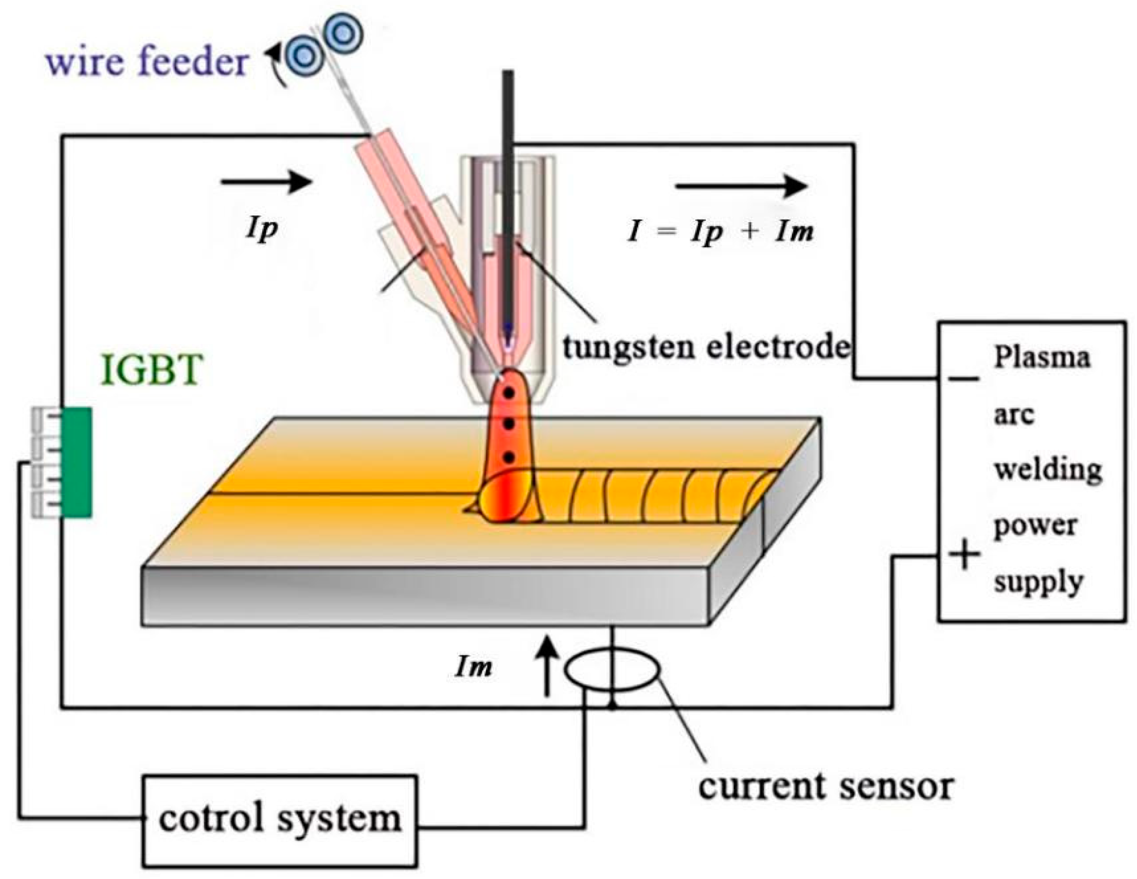
Figure 1. Schematic diagram of titanium alloy bypass current hot wire plasma arc welding.
Metals 12 01949 g001
Figure 2. Force analysis diagram of the molten droplet.
Metals 12 01949 g002
Figure 3. Metal transfer type when the distance between the wire tips and work pieces is 1 mm.
Metals 12 01949 g003
Figure 4. Metal transfer type when the distance between the wire tips and work pieces is 1 mm.
Metals 12 01949 g004
Figure 5. Droplet transfer with the condition of different big bypass current.
Metals 12 01949 g005
Figure 6. Droplet transfer with the condition of different small bypass current.
Metals 12 01949 g006
Figure 7. Sectional appearance of a weld joint containing the weld zone, heat-affected coarse grain zone, heat-affected fine grain zone, transition zone, and base metal zone.
Metals 12 01949 g007
Figure 8. Weld surface morphology: (a) positive forming and (b) back forming.
Metals 12 01949 g008
Figure 9. The microstructure of each characteristic zone of weld joint is (a) weld zone, (b) coarse grain zone, (c) fine grain zone, and (d) transition zone, respectively.
Metals 12 01949 g09aMetals 12 01949 g09b
Figure 10. Stretch stress–displacement curve through bypass current hot wire plasma arc welding compared with the traditional method.
Metals 12 01949 g010
Figure 11. Micro-hardness of the weld joint, (a) bypass hot wire plasma arc welding joint, and (b) traditional filler wire plasma arc welding joint.
Metals 12 01949 g011
Figure 12. Fracture surface morphology: (a) bypass hot wire plasma arc overview welding joint, (b) bypass hot wire plasma arc center zone welding joint, (c) traditional filler wire plasma arc overview welding joint, and (d) traditional filler wire plasma arc center zone welding joint.
Metals 12 01949 g012aMetals 12 01949 g012b
Table 1. Chemical composition of TC4 alloy and wire.
ElementAlVFeCNHOTi
Base5.5–6.753.5–4.50.30.080.050.0150.2Bal
WireTi-6Al-4V
Table 2. Experimental parameters used in this study.
Welding ParametersParameter Values
Main current (A)270
Small main current (A)140–160
Bypass current (A)20
Ionic gas flow rate (L/min)2
Protective gas flow (L/min)17
Wire feeding speed (m/min)3.43
Welding speed (m/min)0.25
Nozzle diameter (mm)3
Distance from nozzle to workpiece (mm)5
Front protective gas flow (L/min)50
Back protective gas flow (L/min)20
Publisher’s Note: MDPI stays neutral with regard to jurisdictional claims in published maps and institutional affiliations.