Abstract
The possibility of hydrometallurgical processing of converter slag from nickel production aimed at integrated use of mineral raw materials and environmental protection is shown. The scheme of hydrometallurgical processing of slag using hydrochloric acid is proposed. The method involves leaching the slag with hydrochloric acid in the presence of ferric ions. The high values of iron and nonferrous metals extraction into the leaching solution are achieved during hydrochloric acid leaching. Silicon is concentrated in an insoluble residue. Liquid extraction was used to extract iron from hydrochloric acid leaching solutions. Silica-containing residues can be successfully used in the construction industry.
1. Introduction
Due to the gradual depletion of mineral resources, obtaining additional products from waste is a fundamental principle of sustainable development [1]. In this connection, research aimed at increasing the complexity of raw materials utilization and recovering valuable elements from waste has been recently developed. Slags from non-ferrous metallurgy plants containing various valuable metals are of particular importance.
The metallurgical complex of the Russian Federation produces more than 80 million tons of slag annually, of which 68.5% are dumped into waste dumps. Slag reserves in dumps are currently at 120 million tons and continue to grow as slag output exceeds its total processing and utilization [2,3]. Slags occupy large areas and cause environmental degradation in adjacent areas due to the gradual leaching of toxic metals from their waste [4,5,6,7,8,9].
In the Orenburg region (Russia), the “Southern Urals Nickel Plant PJSC” (UNKL) was the major polluter in terms of the amount of waste generated. The currently implemented technologies of slag waste processing to extract valuable components do not find positive results [10]. Waste slag masses are moved from place to place, mixed, and as a result of crushing and separation, the content of the 100 mm fraction in the dumps increases, making it much more difficult for further processing. The area occupied by the dumps is expanding due to the winds carrying the fine fraction. On the other hand, even more depleted waste nickel slag reduces the commercial interest in its further disposal. As a result, the utilization of waste nickel slag has not yet been completely solved and it is an acute environmental problem.
The building industry is one way of using slags [5,11,12,13,14,15]. However, the direct use of slags in the construction industry is complicated by several technological features of this type of material. On the one hand, the low activity of slag prevents the synthesis of slag binders. On the other hand, the instability of construction and technical properties, unstable structure, and a large number of metallic impurities does not give reason to consider the involvement of slag in the concrete composition as inert aggregates and fillers. Moreover, hazardous components must be identified and recycled before being used in construction in order to eliminate any risk of dangerous impacts that could affect the ecology of humans and other living beings [16]. In addition, the direct use of slags in the construction industry results in a total loss of base metals.
In recent decades, numerous methods have been developed to extract and utilize valuable metals from slags, including pyro-metallurgical, hydrometallurgical (flotation, chemical leaching or bioleaching) and combined pyro-hydrometallurgical approaches [8,17,18,19,20,21,22]. Since the slags contain a minor part of non-ferrous metals in the form of sulfides and metallized magnetic phase, the hydrometallurgical processes are the most effective in processing this type of waste. Sulfuric acid, hydrochloric acid, chloric acid, nitric acid, iron sulfate or chloride, potassium dichromate, sulfur dioxide and hydrogen peroxide have been suggested for the extraction of metals from slag [6,23,24,25,26,27,28,29]. However, these works are devoted to processing copper production slags and are focused primarily on extracting only non-ferrous metals to a predominant extent [30,31]. The extraction of exclusively non-ferrous metals from slags cannot be commercially feasible, due to the bulk of the production costs are iron, silicon dioxide, and magnesium [32]. Therefore, the search for solutions for integrated slag processing with maximum metal extraction and effective use of the silicate part remains a very urgent task.
This work aims to develop a method of integrated hydrometallurgical processing of waste slags of the Southern Urals Nickel Plant PJSC (UNKL) plant to extract non-ferrous metals and iron in commercial products and obtain a waste rock suitable for application in the construction industry. In addition, mineralogical and chemical slag characterization were investigated in detail.
2. Materials and Methods
2.1. Materials
The initial material was converter slag produced during the conversion of nickel matte obtained during reduction-sulfidation smelting shaft furnaces of sinter from oxidized nickel ores (UNKL, Orenburg region, Russia). Control slag samples were taken from a specialized solid waste storage site at various points to assess the quality of technogenic waste. The dry grinding of slag was carried out in grinding cups on a laboratory roller conveyor with the ratio grinding Bodies:Slag = 4:1 to ensure a material fineness of less than 80 μm. The technical mixture of the 1-octanol and 1-decanol (51.9% and 47.5%, respectively, Crestmont Sdn Bhd, Selangor, Malaysia) and 2-undecanone (Treatt, Suffolk, England) were used as received without any purification. All other reagents employed in the experiments were of analytical reagent grade.
2.2. Characterization Methods
The mineralogical composition of the slag was studied by X-ray diffractometer XRD 6000 (Shimadzu, Kyoto, Japan) with Cu_Kα radiation source. The metallographic studies of the internal structure of the slag were carried out using an Ultraphot-3 (Opton, Jena, Germany) microscope in reflective light, on the ground and polished samples. The structure of slag was studied by scanning electron microscopy using a scanning digital electron microscope with software SEM LEO-420 (ZEISS, Jena, Germany), equipped with the microprobe attachment INKA ENERGY-400 (OXFORD Instrument, Abingdon, UK). The surface area, pore diameter and pore volume were determined according to Brunauer-Emmett-Teller (BET) and Barrett-Joyner-Halenda (BJH) methods from N2 sorption isotherm using a micrometric (TriStar II 3020, Micromeritics, Norcross, GA, USA) surface area and porosity analyzer. The determination of non-ferrous and noble metals in the samples was carried out using the atomic absorption spectrometer “HGA” 4100 ZL (Perkin Elmer, Shelton, CT, USA), emission spectrometer ICPS-9000 (Shimadzu, Kyoto, Japan) and mass spectrometer ELAN 9000 DRC-e (PerkinElmer, Shelton, CT, USA). In order to determine sulfur, the analyzer CS-2000 (ELTRA, Haan, Germany) was used. The gravimetric method was used to determine the silicon content.
2.3. Hydrochloric Acid Leaching Test
Slag leaching was carried out in periodic mode in a 2 L jacketed reactor (Double glass Reactor, XC-2L, Henan, China) containing 1 L slag suspension. In this case, 28 wt.% hydrochloric acid was used to leach slag. Leaching performed in the presence of an oxidizing agent (Fe3+) was taken in stoichiometric or over the amount of the resulting hydrogen sulfide. An iron chloride solution containing 200 g·L−1 Fe(III) was used as an oxidizer. The redox potential was 350–450 mV. The speed of the stirrer was 600 rpm−1. The slag was added to the leaching solution preheated to 50 ± 2 °C. Slag loading into the leaching solution was carried out at a rate of 2.0–2.2 g·min−1. After loading, the slurry was kept stirring for 1–2 h at 80 ± 2 °C. The pulp was filtered through a Buchner funnel. The undissolved residue was first washed with hydrochloric acid at solid-liquid ratio (S:L) = 1:3–5 to reduce the loss of metals with the discharge solution, then washed with distilled water for neutral reaction. The washing hydrochloric acid was used in the leaching stage.
2.4. Solvent Extraction Test
The selected volumes of aqueous (A) and organic (O) phases were placed in a separatory funnel and mixed vigorously for 5 min. After phase disengagement, the raffinate was separated for the determination of concentrations of contained metals. Iron stripping was carried out in the separatory funnel by distilled water for 5 min. After the phase settle, the aqueous phase was separated from the organic phase. All of the processes of solvent extraction and stripping were carried out at room temperature (20 ± 2 °C).
The distribution coefficient (D) were calculated follows equation:
Co is a metal concentration in an organic phase, g·L−1; Cr is a metal concentration in raffinate, g·L−1.
3. Results and Discussion
3.1. Characterization of Nickel Converter Slag
A chemical composition analysis was performed for all specimens. The obtained data on chemical composition and the number of control points are presented in Table 1.

Table 1.
The chemical composition of slag samples from different points of the slag dump.
According to X-ray phase analysis, fayalite (Fe2SiO4) was the main mineral component of the initial slag samples (Figure 1); magnetite (Fe3O4) was found in smaller amounts. The deviation from the number of phases in the quantitative content was observed in the following ranges: 15–40% magnetite and 60–85% fayalite. A deviation from the standard in the spectrum of magnetite was also recorded. This shift in the spectra is due to the isomorphic impurities’ inclusion of nonferrous and light metals in the magnetite structure [33]. The silicate part of the slag on the X-ray was represented by a group of lines, an isomorphic compound of variable composition (Fe,Ca,Mg)(SiO4) with the olivine-fayalite structure.
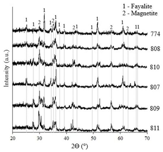
Figure 1.
XRD patterns of samples of converter slag.
The samples selected differ in coloring, granularity, and glassiness. Colors are divided mainly into two colors: light grey (the most common) and black (the rarest). Upon crushing, black specimens were observed to be more brittle under load than grey specimens. Figure 2 represents the X-ray patterns of these samples. As can be seen, the light grey samples are X-ray amorphous, and the black ones, based on the intensity of the lines, have a greater degree of crystallinity.
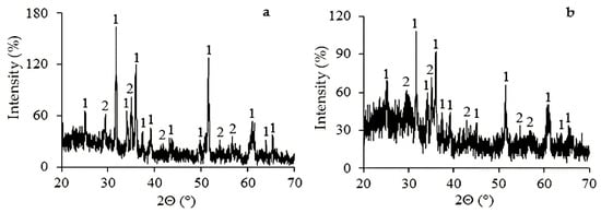
Figure 2.
XRD patterns of slag samples varieties: (a)—black color, (b)—light gray color: 1—fayalite, 2—magnetite.
The metallographic samples were prepared by embedding the solid specimen in epoxy resin and polishing. A mineralogical analysis of the slag showed that the slag was a complex heterogeneous formation that consisted of crystalline and amorphous matter, with inclusions of phenocrysts of sulfides and oxides. As a result of the microscopic examination of the slag, the main mineral constituents were fayalite, which did not contain impurities in its composition, and magnetite, and also kirschstenite, olivine and augite, which differed in their contents (Figure 3 and Figure 4).
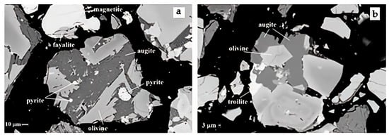
Figure 3.
SEM micrograph of slag showing components of the slag: (a)—sample 807, (b)—sample 809.
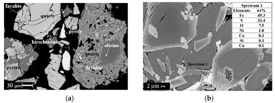
Figure 4.
SEM micrograph of slag showing components of the slag: (a)—sample 807, (b)—sample 809.
Inclusions of sulfides in the slag are distributed unevenly and not in all grains of the mass (matrix slag) consist of fayalite and magnetite. Sulfides generally have a round shape (balls, drops), and less common oval excretions and complex sulfide formations with a curvilinear shape are found. The size of sulfides vary from 5 to 30 microns. Smelting captures some of the nickel from the sulfide components of the slag, which, in turn, concentrates the iron-nickel matte. Cobalt, as an associated nickel metal, passes almost all into the slag, where it was accumulated in silicate phases rather than being extracted as a metallic phase (Figure 4b).
The mineralogical analysis allowed us to conclude that non-ferrous metals are contained in all slag phases. This fact predetermines the hydrometallurgical approach to processing waste, as the deep extraction by magnetic separation or flotation will not have a positive result.
3.2. Hydrochloric Acid Leaching Studies
Based on the mineralogical composition of the slag determined by XRD, the process of decomposition of its target soluble forms by hydrochloric acid can be represented by the following chemical reactions:
where Me—metal (Fe, Ni, Cu, Mg and other).
where Me—metal (Fe, Ni, Cu and Co).
Me2SiO4 + 4HCl = 2MeCl2 + SiO2 + 2H2O,
MeS + 2HCl = MeCl2 + H2S↑
MeS2 + 2HCl = MeCl2 + H2S↑ + S↓
Hydrochloric acid decomposition of slag was carried out according to the previously developed approach of metallurgical Cu-Ni converter slag processing [34]. According to the method, slag leaching occurs in 28 wt.% hydrochloric acid at 80 ± 2 °C in the presence of oxidizing agent (Fe3+) and portion loading of slag into the hydrochloric acid solution. The portion loading of slag into the concentrated hydrochloric acid solution provides good filterability of the solid phase residue and reduces the silicon transfer into the solution [35]. Adding an oxidizing agent into the hydrochloric acid solution makes it possible to limit the release of hydrogen sulfide in the reaction volume and prevents its release into the atmosphere of the working area during slag leaching. An oxidizing process of hydrogen sulfide binding in the presence of an oxidizer can be represented by the following reaction:
H2S + 2FeCl3 = 2FeCl2 + 2HCl + S0
Since the addition of iron chloride solution to the hydrochloric acid leaching solution dilutes it, the effect of iron content on the recovery of target components was studied using sample 774 (Table 2). A sample containing mainly fayalite (sample 774) and an averaged sample 813 obtained by mixing specimens 807–812 were used for hydrochloric acid leaching studies.

Table 2.
The influence of iron concentration in the initial hydrochloric acid solution on the leaching of slag sample 774. Conditions: t = 80 ± 2 °C, S:L = 1:10, τ = 5 h.
As can be seen from the data presented in Table 2, reducing the concentration of hydrochloric acid leads to a negligible decrease in the extraction percentage of the target components. At the same time, the sulfur content in the insoluble residue increases, which indicates the effectiveness of the iron (III) ions being introduced into the reaction mass to prevent the release of hydrogen sulfide in the process of slag leaching.
The influence of the S:L ratio on the extraction of the Fe and non-ferrous metals was studied (Table 3). The results demonstrated that increasing the S:L ratio leads to an insignificant increase in the degree of decomposition of slag components and dilution of the resulting filtrate. The optimal ratios of S:L = 1:4–5 make achieving iron-concentrated filtrates possible.

Table 3.
The influence of solid-liquid ratio on the leaching of a slag sample 774. Conditions: t = 80 °C, CFe = 20 g·L−1, CHCl = 25.6%, τ = 5 h.
Experiments for studying the effect of leaching time on the extraction percentages of target components were performed in the solution mixture of 25.6 wt.% HCl and 20 g·L−1 Fe3+ with a solid-liquid ratio of 1:5 at 80 ± 2 °C for 0–6 h (Figure 5). Samples of slag that were different in mineral and chemical composition—samples 774 and 813—were selected for these studies. Since the slag was loaded in portions during the first two hours, the sampling was started after 2.5 h. The experimental results revealed that all component extraction percentages increased with increasing leaching time. However, the extraction percentages of iron, calcium, aluminum and magnesium in the leaching solution during the decomposition of sample 813 were lower than those of sample 774; this was due to the inclusion of these elements in the mineral augite—a chemically stable mineral. The extraction of non-ferrous metals in the leaching solution is steadily high (85–100%). Note that loading the slag in portions resulted in insignificant extraction of silicon in the leaching solution (0.03–0.05%). The concentration of silicon in the leaching solution was 5–7 ppm. A comparison of residue composition after leaching of samples 813 and 774 was presented in Table 4.
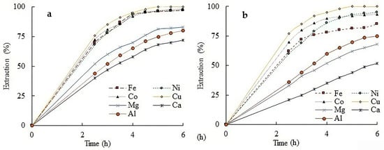
Figure 5.
The extraction percentages of target components from converter slag (Sample 774 and Sample 813) as a function of leaching time (a—Sample 774; b—Sample 813). Conditions: t = 80 °C, CFe3+ = 20 g·L−1, CHCl = 25.6 wt.%, S:L = 1:5.

Table 4.
The residue composition of slag leaching with hydrochloric acid (Sample 813). Conditions: t = 80 ± 2 °C, CFe = 20 g·L−1, CHCl = 25.6%, S:L = 1:5, τ = 6 h.
As shown in Table 3 and Figure 5, the overall extraction rates of the target components are higher than their extraction into the filtrate. The reason is that the undissolved residue after slag leaching contains significant amounts of metal chlorides. The metal extraction in the washing solution washed with water had percentage ranges of: 10–12 Fe, 16–18 Ni, 18–20 Co, 18–20 Cu. Thus, to optimize the leaching process and reduce the loss of valuable components, the residue was initially washed with a hydrochloric acid solution and then with water. The undissolved residue was washed with 28 wt.% hydrochloric acid solution at 50 °C for 30 min in repulsion mode. A volume of acid necessary in order to leach the slag was taken for washing. This solution was used in the slag decomposition stage. Table 5 shows the compositions of solutions and residueas well as the degree of extraction of valuable components in the process of slag leaching with hydrochloric acid washing solution. The data presented in the Table 5 were obtained by processing Sample 813 mass 1 kg in batch mode. As can be seen from the data presented in Table 5, the additional operation of washing the undecomposed residue with hydrochloric acid and its use at the stage of leaching allows for the obtainment of more concentrated content of the target components, as well as reducing their losses with the washing solution.

Table 5.
Valuable component distribution in slag leaching with hydrochloric acid washing solution (Sample 813). Conditions: t = 80 ± 2 °C, S:L = 1:5, τ = 5 h.
According to the X-ray phase analysis, the basis of the residue after hydrochloric acid leaching was an amorphous phase with crystalline phases of augite and sulfur (Figure 6). The residual humidity was 7–15%. The value of the BET specific surface area of the silicon-containing residue was found to be 250–300 m2·g−1. The use of such material in the construction industry is directed towards reducing the cost of production [36].
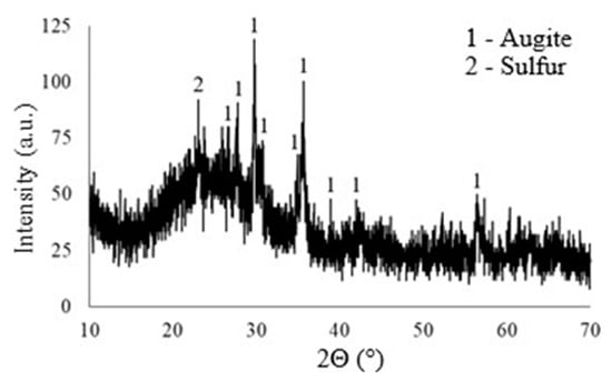
Figure 6.
X-ray diffraction patterns of residue after leaching by 28% hydrochloric acid.
The residue after hydrochloric acid leaching was dissolved in 4N NaOH solution, then diluted in CCl4 to remove sulfur and boiled in concentrated hydrochloric acid. The reduction in the residue after decomposition of sample 774 was 68%, and the total decrease from the initial slag sample was 87%. The residue reduction after decomposition of sample 813 was 44%, and the total decrease from the original slag sample was 65%. Thus, the insoluble part of the slag is about 13% in sample 774 and 35% in sample 813. According to X-ray phase analysis, the basis of the residue after additional treatment is hard-soluble mineral augite (Ca,Mg,Fe,Al)(Si,Al)2O (Figure 7). Residue composition, wt.%: 21.7–26.0 Si, 10.5–11.8 Fe, 8.5–10.1 Ca, 2.9–3.6 Al, 2.8–3.7 Mg.
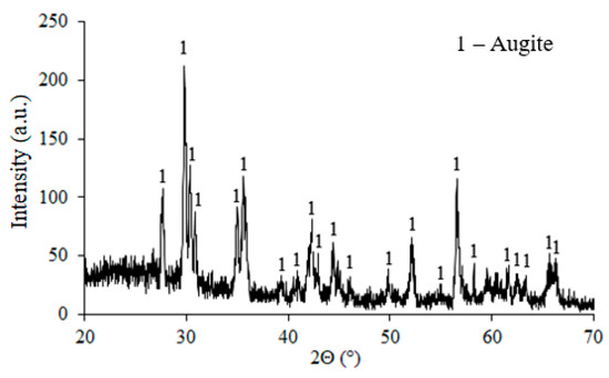
Figure 7.
X-ray diffraction patterns of augite.
The electron probe micro-analyzer (EPMA) images of the augite show the distribution of elements (Figure 8). Color modification showed that all components were distributed on the sample sufficiently uniformly.
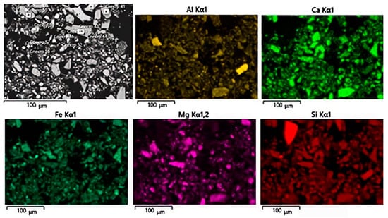
Figure 8.
EDAX map of elements distribution.
The solutions obtained by hydrochloric acid leaching of slag contain g·L−1: 60–120 Fe, 0.6–1.0 Ni, 0.2–0.3 Co, 0.03–0.05 Cu, 1.5–5.3 Mg, and 3.2–4.6 Ca, and can be used for subsequent separation by extraction methods of iron and nonferrous metals and production of magnesium hydroxides.
3.3. Solvent Extraction of Iron from Slag Leaching Solution
A prerequisite for the economic efficiency of hydrochloric acid technology is the ability to regenerate hydrochloric acid. The pyrohydrolysis of purified iron(III) chloride solution solutions may be the most effective method for regeneration. For the extraction of iron(III) from its concentrated solutions, liquid extraction is the most suitable method. We considered the possibility of selective extraction of iron from slag-leaching solutions using alcohols and ketones as extractants. Since iron is present as iron(II) in the slag leaching solution, its quantitative oxidation for subsequent extraction is necessary. Oxidation was carried out with chlorine according to the method [37]. Previously, we have shown that mixtures of aliphatic alcohols and ketones effectively extract iron from chloride solutions of various compositions [38,39]. As a result, it was found that an extractant containing 70 vol.% of a technical mixture of 1-octanol and 1-decanol and 30 vol.% of 2-undecanone is optimal for iron(III) extraction. However, the concentration of iron in the solution did not exceed 15 g·L−1. In the present study, the use of extracting iron from the slag leaching solution was examined using a mixture of this composition. Figure 9 presents the McCabe-Thiele plot for iron extraction from a solution of hydrochloric acid leaching of slag was obtained (Figure 9). The complete extraction of iron occurs in 4, 3, and 2 stages at a ratio of the organic phase to the aqueous phase (O:A), respectively, 1:1, 2:1, and 3:1.
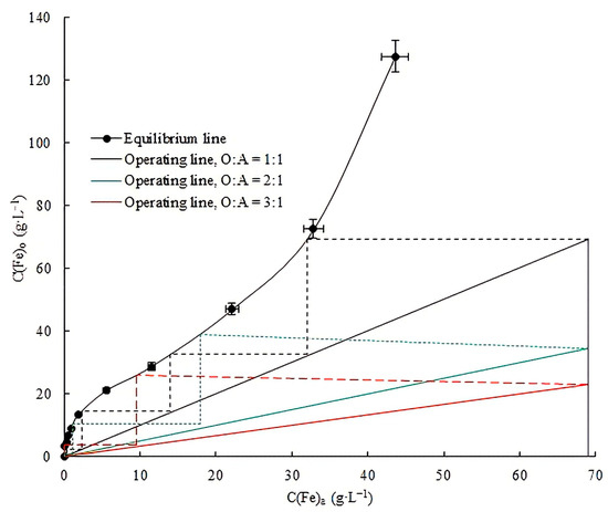
Figure 9.
McCabe-Thiele plot for iron extraction. C(Fe3+)a = 69.1 g·L−1, t = 20 °C, τ = 5 min.
To reduce the number of extraction stages, the ratio O:A = 3:1 was used at two stages. The concentration of some metals in the initial solution and in the raffinate, and the logarithm of the distribution coefficient of metals during extraction, are shown in Figure 10. The concentration of iron in the aqueous solution decreased from 67.4 to 0.001 g·L−1. Moreover, the minimum amount of non-ferrous metals was extracted into the organic phase. It can be assumed that the low co-extraction of impurities is associated with a high concentration of iron in the initial solution. As a result, iron displaces non-ferrous metals already at the extraction stage. Thus, after two extraction stages, a raffinate was obtained containing g·L−1: Fe—0.001, Al—3.14, Ca—4.70, Mg—5.50, and Ni—1.35. The resulting solution is directed either to the slag leaching stage or to further processing to extract the remaining non-ferrous metals.
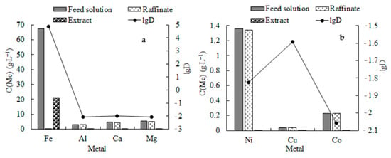
Figure 10.
The results of solvent extraction of iron(III) from slag leaching solution. (a)—Fe, Al, Ca, Mg); (b)—Ni, Co, Cu. O:A = 3:1, 2 stages, t = 20 °C, τ = 5 min.
The resulting extract is directed for stripping to obtain a ferric chloride solution. Previously, we have shown that an almost complete stripping from the organic phase containing 20 g·L−1 of iron is possible in 2 steps at a ratio of O:A = 2:1 [39]. In this case, to obtain a more concentrated strip solution, stripping was carried out at a ratio of O:A = 3:1. The stripping was carried out by 0.2 M HCl solution in order to avoid a third phase formation. From the McCabe-Thiele plot for iron stripping, it was found that the iron passed to the aqueous phase in 3 stages (Figure 11). As a result, from the extract obtained during the extraction, containing 21 g·L−1 of iron, a strip solution was obtained, g·L−1: Fe—62.9, Ni—0.004, Al—0.030, Ca—0.045, Mg—0.042. Thus, the solution obtained can be directed to evaporation to receive a concentrated ferric chloride solution, which is often used as a coagulant [40].
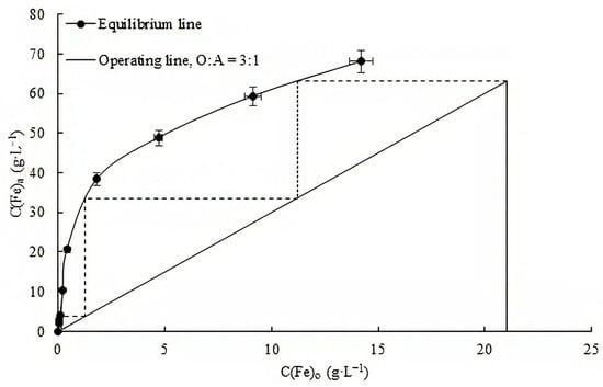
Figure 11.
McCabe-Thiele plot for iron extraction. C(Fe3+)a = 69.1 g·L−1, t = 20 °C, τ = 5 min.
The conceptual flow sheet of hydrochloric acid slag leaching is shown in Figure 12. According to the scheme, the crushed converter slag is leached in a 28% hydrochloric acid solution in the presence of an oxidizer (Fe3+) with conversion to a leaching solution of iron and non-ferrous metals. The solution is then subjected to extraction processing to obtain an iron chloride solution free of non-ferrous metals. Pure iron oxide is obtained from the solution by pyrohydrolysis. Given the composition of the solution and the low concentration of base metals, the subsequent separation of elements was carried out by their precipitation at a controlled pH. Initially, aluminium hydroxide was precipitated, and then non-ferrous metals were precipitated. After extraction of non-ferrous metals, magnesium hydroxide was precipitated. The leaching residue is proposed for use in the building industry. We are currently studying the possibility of using the residue from hydrochloric acid leaching of converter slag as an active additive in cement.
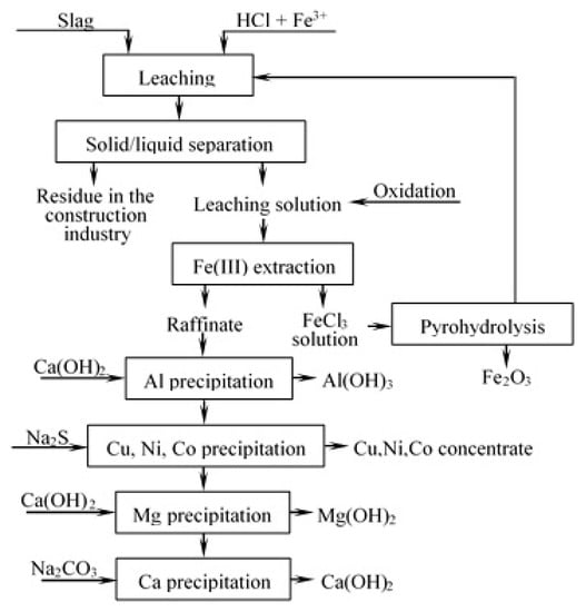
Figure 12.
A conceptual flow sheet for leaching of slag with HCl.
4. Conclusions
- Mineralogical and chemical analyses of converter nickel slag from the “Southern Urals Nickel Plant PJSC” (UNKL) showed that the slag is characterized by an uneven distribution of the target components throughout the slag dump.
- Mineralogical composition is the most significant factor that influences the leaching of slag components. It is shown that the sparingly soluble form of augite in slags reduces the degree of extraction of iron, magnesium and calcium, which are part of this mineral.
- Large-scale laboratory tests confirmed that the proposed process is applicable to the total volume of slag. With this process used in industry, it is possible to involve in processing large volumes of nickel-cobalt technogenic raw materials.
- The possibility of the extraction processing of filtrates from slag decomposition using a mixture of alcohols and ketone as an extractant to obtain concentrated solutions of iron chlorides has been established.
- Obtained using the proposed scheme, silicon-containing residue is characterized by a high specific surface area (250–300 m2·g−1). The use of such material in construction industry is directed towards reducing the cost of production.
- The main advantage of the proposed hydrometallurgical slag processing scheme is the possibility of selective separation of iron from non-ferrous metals with the release of all valuable components into marketable products and the use of the insoluble residue in the construction industry.
- Two urgent tasks at once—providing technogenic raw materials for the production of new and traditional building materials and eliminating the negative impact of waste on the environment during their storage—can be solved through the use of slag processing products in the construction industry.
Author Contributions
Conceptualization, A.G.K., E.A.S., O.A.T. and A.Y.S.; methodology, A.G.K., E.A.S. and A.Y.S.; software, A.G.K., E.A.S. and A.Y.S.; validation, A.G.K., E.A.S. and A.Y.S.; formal analysis, A.G.K., E.A.S. and A.Y.S.; investigation, A.G.K., E.A.S. and A.Y.S.; resources, A.G.K., E.A.S. and A.Y.S.; data curation, A.G.K., E.A.S. and A.Y.S.; writing—original draft preparation, E.A.S. and A.Y.S.; writing—review and editing, A.G.K. and A.Y.S.; visualization, E.A.S. and A.Y.S.; supervision, A.G.K., E.A.S. and A.Y.S. All authors have read and agreed to the published version of the manuscript.
Funding
This study is supported by the Ministry of Science and Higher Education Russian Federation scientific topic No FMEZ-2022-0018.
Institutional Review Board Statement
Not applicable.
Informed Consent Statement
Not applicable.
Data Availability Statement
All data are available in this study.
Acknowledgments
The authors would like to acknowledge Vasiliy Semushin (Tananaev Institute of Chemistry) for performing the SEM measurements.
Conflicts of Interest
The authors declare no conflict of interest.
References
- Panfilov, M.I.; Shkol’nik, J.S.; Orininskiy, N.V. Pererabotka Shlakov i Bezotkhodnaya Tekhnologiya v Metallurgii; Metallurgiya: Moscow, Russia, 1987. [Google Scholar]
- Aksenov, E.M.; Sadykov, R.K.; Aliskerov, V.A.; Kiperman, J.A.; Komarov, M.A. Technogenic Deposits—Problems and involving prospects in economic circulation. Prospect Prot. Miner. Resour. 2010, 2, 17–20. [Google Scholar]
- Bykhovsky, L.Z.; Sporykhina, L.V. Industrial waste as a reserve to replenish mineral recourses: Status and development problems. Minerals Recourses of Russia. Econ. Manag. 2021, 4, 15–20. [Google Scholar]
- Potapov, D.S.; Svetlov, A.V.; Potapov, S.S.; Men’shikov, Y.P.; Nesterov, D.P.; Makarov, D.V. Experimental modeling of weathering uneven slag copper-nickel production. Mineral. Tekhnogenezisa 2013, 14, 38–49. [Google Scholar]
- Tyszka, R.; Kierczak, J.; Pietranik, A.; Ettler, V.; Mihaljevič, M. Extensive weathering of zinc smelting slag in a heap in Upper Silesia (Poland): Potential environmental risks posed by mechanical disturbance of slag deposits. Appl. Geochem. 2014, 40, 70–81. [Google Scholar] [CrossRef]
- Piatak, N.M.; Parsons, M.B.; Seal, R.R., II. Characteristics and environmental aspects of slag: A review. Appl. Chem. 2015, 57, 236–266. [Google Scholar] [CrossRef]
- Khalilova, H.K. The problems of the negative environmental impact of chemical pollutants and possible ways of their prevention. Chem. Probl. 2019, 4, 500–517. [Google Scholar] [CrossRef]
- Habib, A.; Bhatti, H.N.; Iqbal, M. Metallurgical processing strategies for metals recovery from industrial slag. Z. Phys. Chem. 2020, 234, 201–231. [Google Scholar] [CrossRef]
- Ivankov, S.I.; Troitskiy, A.V. Ekologicheskiye aspekty pererabotki nikel’-kobal’tovogo rudnogo i tekhnogennogo syr’ya. Nauchnyye I Tekhnicheskiye Asp. Okhrany Okruz. Sredy 2019, 4, 2–87. [Google Scholar]
- Veselovskiy, A.A.; Laihan, S.A. Methodology for non-waste recycling of dump nickel slag. Bull. South Ural. State Univ. Ser. Metallurgy 2019, 19, 62–70. [Google Scholar]
- Wang, G.C. Philosophy of utilization of slag in civil infrastructure construction. In The Utilization of Slag in Civil Infrastructure Construction; Woodhead Publishing: Sawston, UK, 2016; pp. 115–129. [Google Scholar]
- Šafránek, M.; Vozňáková, I. Use of slug in the construction industry. In Proceedings of the 28th International Conference on Metallurgy and Materials (Metal 2019), Brno, Czech Republic, 22–24 May 2019; pp. 2002–2006. [Google Scholar]
- Sande, J.V.D.; Peys, A.; Hertel, T.; Rahier, H.; Pontikes, Y. Upcycling of non-ferrous metallurgy slags: Identifying the most reactive slag for inorganic polymer construction materials. Resour. Conserv. Recycl. 2020, 154, 104627. [Google Scholar] [CrossRef]
- Liu, K.; Wang, Y.; Lonh, H.; Cheng, Y.; Wu, Y.; Cai, Y.; Jiang, J. Recovery of cobalt and nickel from magnesium-rich sulfate leach liquor with magnesium oxide precipitation method. Miner. Eng. 2021, 169, 106964. [Google Scholar] [CrossRef]
- Liu, Q.; Li, J.; Lu, Z.; Li, X.; Jiang, J.; Niu, Y.; Xiang, Y. Silicomanganese slag: Hydration mechanism and leaching behavior of heavy metal ions. Constr. Build. Mater. 2022, 326, 126857. [Google Scholar] [CrossRef]
- Wang, G.C. Environmental aspects of slag utilization. In The Utilization of Slag in Civil Infrastructure Construction; Woodhead Publishing: Sawston, UK, 2016; pp. 131–153. [Google Scholar]
- Banda, W.; Morgan, N.; Ekseteen, J.J. The role of slag modifiers on the selective recovery of cobalt and copper from waste smelter slag. Miner. Eng. 2002, 15, 899–907. [Google Scholar] [CrossRef]
- Carranza, F.; Iglesias, N.; Mazuelos, A.; Romero, R.; Forcat, O. Ferric leaching of copper slag flotation tailings. Miner. Eng. 2009, 22, 107–110. [Google Scholar] [CrossRef]
- Geng, C.; Wang, H.-J.; Hu, W.-T.; Li, L.; Shi, C.-S. Recovery of iron and copper from copper tailings by coal-based direct reduction and magnetic separation. J. Iron Steel Res. Int. 2017, 24, 991–997. [Google Scholar] [CrossRef]
- Potysz, A.; Kierczak, J. Prospective (Bio)leaching of historical copper slags as an alternative to their disposal. Minerals 2019, 9, 542. [Google Scholar] [CrossRef]
- Mikula, K.; Izydorczyk, G.; Skrzypczak, D.; Moustakas, K.; Witek-Krowiak, A.; Chojnacka, K. Value-added strategies for the sustainable handling, disposal, or value-added use of copper smelter and refinery wastes. J. Hazard. Mater. 2021, 403, 123602. [Google Scholar] [CrossRef]
- Topçu, M.A.; Rüşen, A.; Küçük, O. Treatment of copper converter slag with deep eutectic solvent as green chemical. Waste Manag. 2021, 132, 64–73. [Google Scholar] [CrossRef] [PubMed]
- Ahmed, I.M.; Nayl, A.A.; Daoud, J.A. Leaching and recovery of zinc and copper from brass slag by sulfuric acid. J. Saudi Chem. Soc. 2016, 20, S280–S285. [Google Scholar] [CrossRef]
- Ying, S.; Jing, Z.; Yan-ze, W.; Qiu-ju, L. Experimental Study on Valuable Metals Dissolution from Copper Slag. In Rare Metal Technology; Alam, S., Kim, H., Neelameggham, N.R., Ouchi, T., Oosterhof, H., Eds.; Springer: Cham, Switzerland, 2016. [Google Scholar]
- Nadirov, R.K.; Mussapyrova, L. Copper smelter slag leaching by using H2SO4 in the presence of dichromate. J. Chem. Technol. Metall. 2019, 54, 657–662. [Google Scholar]
- Feng, Y.; Kero, J.; Yang, Q.X.; Chen, Q.S.; Engstrom, F.; Samuelsson, C. Mechanical activation of granulated copper slag and its influence on hydration heat and compressive strength of blended cement. Materials 2019, 12, 772. [Google Scholar] [CrossRef]
- Khalid, M.K.; Hamuyuni, J.; Agarwal, V.; Pihlasalo, J.; Haapalainen, M.; Lundstrom, M. Sulfuric acid leaching for capturing value from copper rich converter slag. J. Clean. Prod. 2019, 215, 1005–1013. [Google Scholar] [CrossRef]
- Nadirov, R.; Syzdykova, L.; Zhussupova, A. Copper smelter slag treatment by ammonia solution: Leaching process optimization. J. Cent. S. Univ. 2017, 24, 2799–2804. [Google Scholar] [CrossRef]
- Mussapyrova, L.; Nadirova, R.; Baláž, P.; Rajňákd, M.; Bureš, R.; Baláž, M. Selective room-temperature leaching of copper from mechanically activated copper smelter slag. J. Mater. Res. Technol. 2021, 12, 2011–2025. [Google Scholar] [CrossRef]
- Phiri, T.C.; Singh, P.; Nikoloski, A.N. The potential for copper slag waste as a resource for a circular economy: A review—Part II. Miner. Eng. 2021, 172, 107150. [Google Scholar] [CrossRef]
- Zhai, Q.; Liu, R.; Wang, C.; Wen, X.; Li, X.; Sun, W. A novel scheme for the utilization of Cu slag flotation tailings in preparing internal electrolysis materials to degrade printing and dyeing wasterwater. J. Hazard. Mater. 2022, 24 Pt B, 127537. [Google Scholar] [CrossRef]
- Kasikov, A.G. Sever i Rynok: Formirovaniye ekonomicheskogo poryadka (ISSN 2220-802X). Kola Sci. Cent. 2013, 1, 48–52. [Google Scholar]
- Miroyevskiy, G.P.; Popov, I.O.; Golov, A.N.; Koklyanov, Y.B.; Keller, V.V. Podgotovka mednykh konverternykh shlakov k gidrometallurgicheskoy pererabotke. Tsvetnyye Met. 2001, 2, 127–129. [Google Scholar]
- Kasikov, A.G.; Mayorova, E.A. Slag Digestion Method. RU Patent 2568796, 20 November 2015. [Google Scholar]
- Binnemans, K.; Jones, P.T.; Fernández, Á.M.; Torres, V.M. Hydrometallurgical Processes for the Recovery of Metals from Steel Industry By-Products: A Critical Review. J. Sustain. Metall. 2020, 6, 505–540. [Google Scholar] [CrossRef]
- Richard, P.; Cheyrezy, M. Composition of reactive powder concretes. Cem. Concr. Res. 1995, 25, 1501–1511. [Google Scholar] [CrossRef]
- Saji, J.; Reddy, M.L.P. Liquid–liquid extraction separation of iron III from titania wastes using TBP–MIBK mixed solvent system. Hydrometallurgy 2001, 61, 81–87. [Google Scholar] [CrossRef]
- Sokolov, A.; Valeev, D.; Kasikov, A. Solvent Extraction of Iron(III) from Al Chloride Solution of Bauxite HCl Leaching by Mixture of Aliphatic Alcohol and Ketone. Metals 2021, 11, 321. [Google Scholar] [CrossRef]
- Kasikov, A.; Sokolov, A.; Shchelokova, E. Extraction of Iron(III) from Nickel Chloride Solutions by Mixtures of Aliphatic Alcohols and Ketones. Solvent Extr. Ion Exch. 2022, 40, 251–268. [Google Scholar] [CrossRef]
- Lin, L.; Li, R.-H.; Yang, Z.-Y.; Li, X.-Y. Effect of coagulant on acidogenic fermentation of sludge from enhanced primary sedimentation for resource recovery: Comparison between FeCl3 and PACl. Chem. Eng. J. 2017, 325, 681–689. [Google Scholar] [CrossRef]
Publisher’s Note: MDPI stays neutral with regard to jurisdictional claims in published maps and institutional affiliations. |
© 2022 by the authors. Licensee MDPI, Basel, Switzerland. This article is an open access article distributed under the terms and conditions of the Creative Commons Attribution (CC BY) license (https://creativecommons.org/licenses/by/4.0/).