Article

Achieving a Combination of Higher Strength and Higher Ductility for Enhanced Wear Resistance of AlCrFeNiTi0.5 High-Entropy Alloy by Mo Addition

The Department of Chemical and Materials Engineering, University of Alberta, Edmonton, AB T6G 2H5, Canada
*
Author to whom correspondence should be addressed.
Metals 2022, 12(11), 1910; https://doi.org/10.3390/met12111910
Submission received: 1 October 2022 / Revised: 4 November 2022 / Accepted: 4 November 2022 / Published: 8 November 2022
(This article belongs to the Special Issue Wear and Corrosion Behavior of High-Entropy Alloy)

Abstract

:
AlCrFeNiTi0.5Mox (x = 0, 0.1, 0.2, 0.3 and 0.4) high-entropy alloys (HEAs) were prepared by arc melting and investigated in terms of microstructure, mechanical properties, and wear resistance. All the as-cast HEAs are composed of one disordered BCC phase (BCC) and one ordered BCC (B2) phase. The added Mo acted as a solid solute in the BCC phase. When Mo molar ratio was more than 0.3, a new type or modified BCC phase formed at the grain boundary, which was enriched with both Mo and Ti. Strength, hardness, and ductility of AlCrFeNiTi0.5 were markedly increased with the Mo addition. The increase in hardness was caused by Mo-solute strengthened disordered BCC phase and precipitation-strengthening by precipitation of hard (Mo, Ti)-rich BCC phase at grain boundaries. The improved ductility was largely attributed to reduced interfacial lattice mismatch between the BCC and B2 phase. The Mo-free AlCrFeNiTi0.5 showed the highest wear loss, about 2.5 times as large as that of AlCrFeNiTi0.5Mo0.4 alloy, which possessed the highest hardness, yield strength, maximum strength, and ductility.

1. Introduction

High-entropy alloys (HEAs) have received considerable attention due to their distinctive microstructure and attractive properties. HEA was initially defined as an alloy containing at least five principal elements in equiatomic or near-equiatomic concentrations [1,2,3,4]. Due to its high entropy, this multi-principal element alloy tends to form a simple solid solution with face-centered cubic (FCC) structure, body-centered cubic (BCC) structure, or hexagonal closed-packed (HCP) structure [5]. The solid-solution hardening caused by multi-elements with large lattice distortion in a simple solid-solution structure makes it possible to obtain high strength/hardness and desired toughness [6,7,8,9,10,11,12]. In addition to the high entropy and lattice distortion effects, there are two other beneficial core effects for HEA, called sluggish diffusion effect and cocktail effect [13]. Due to these unique effects, HEAs also possess other wished-for capabilities, such as excellent high-temperature strength, corrosion resistance, wear resistance, irradiation resistance, high toughness, and thermal stability, etc. [14,15,16,17,18,19,20,21].
Many studied HEAs are based on the FeCoNiCr alloy systems with a single FCC structure [7,18,22,23,24]. For example, FeCoNiCrMn with a single FCC structure is one of the earliest and most-studied HEAs, named the “Cantor alloy” [25,26]. Like most FCC structured alloys, the Cantor alloy exhibits high ductility (about 50%) but low yield strength, usually below 400 MPa at room temperature [27,28]. The BCC or B2 (ordered BCC) structure is generally found to have higher hardness and strength than the FCC phase, due to its larger energy barrier to dislocation generation and movement, at the expense of ductility [29,30]. Tian et al. [31] showed that AlxCrFeCoNi had a threefold increase in hardness when the alloy changed its FCC structure (at x = 0.3) to a BCC + B2 structure (at x = 1). Here, BCC phase is a disordered BCC phase, whereas B2 is an ordered BCC phase as indicated earlier. Properties of HEA are relatively easy to be tuned by changing its combination of multi-elements. It has been noticed that Co-free AlCrFeNi alloy, which consists of BCC phase and B2 phase, exhibits relatively high yield strength (1075 MPa) with a fairly high fracture strain (43.8%) [32]. Titanium is another element that shows distinct effects on mechanical properties of the HEA. Due to its large atomic radius, titanium has a strong solid-solution strengthening effect on the ordered B2 phase in AlCrFe(Co)Ni alloy, considerably increasing hardness, strength and wear resistance of the alloy [33,34,35,36]. However, if Ti content is sufficiently high (molar ratio x > 5), the formation of intermetallic phases make the HEA brittle, which is detrimental to the fracture roughness and wear resistance of the alloy [37,38].
In this study, we modified AlCrFeNiTi0.5 alloy that consisted of a disordered BCC phase (denoted as BCC) and ordered BCC phase (B2) by using an additional element, Mo. Mo is considered to be an element for the pursuit of a combination of high strength and acceptable toughness [39,40,41,42,43]. It has been reported that the Mo addition in FCC-structured CoCrFeNi [41], CoCrFeMnNi [42], and Al0.5CoCrFeNi [43] alloys increases hardness via substitutional solute strengthening and reduces the wear rate. Mo promotes precipitation of hard and brittle (Cr, Mo)-rich σ and (Mo, Cr)-rich µ phases in the FCC solid solution [41,42,44]. Properly controlling the Mo content could further strengthen the alloy without losing much ductility or keeping reasonable toughness. However, previous studies on the effect of Mo addition on mechanical properties and wear were mainly conducted for FCC HEAs. There are very limited studies on the effect of Mo addition on BCC HEAs. In addition, Mo is more likely to be enriched in the FeCr-rich phase of FCC-structured HEA. For BCC-structured AlCrFeNiTi0.5 alloy, where Mo stays and how or whether or not it influences properties of the alloy are unclear. This study was designed to investigate the effect of Mo addition on microstructure, mechanical properties, and wear resistance of AlCrFeNiTi0.5Mox HEAs (where x was in a range of 0–0.4). As shown in this study, with Mo addition, AlCrFeNiTi0.5 exhibited increased strength with elevated ductility simultaneously. The wear resistance was considerably improved. In this article, underlying mechanisms are elucidated.

2. Materials and Methods

Ingots of high-entropy alloys under study with nominal compositions of AlCrFeNiTi0.5, AlCrFeNiTi0.5Mo0.1, AlCrFeNiTi0.5Mo0.2, AlCrFeNiTi0.5Mo0.3, and AlCrFeNiTi0.5Mo0.4 (named T5, T5M1, T5M2, T5M3 and T5M4, hereafter) were produced by arc melting raw metal powders (purity ≥ 99.5 at. %) with a water-cooled copper crucible in argon atmosphere. The ingots were flipped and remelted at least four times to minimize compositional inhomogeneity. Samples with dimensions of 15 mm × 15 mm × 3 mm were cut from the alloy ingots by using an electrical discharge wire-cutter, which were subsequently ground with SiC papers up to 1200 grits, and finally polished by using a 0.1 μm alumina suspension.
X-ray diffraction analysis was conducted for the samples by using a Bruker D8 Discover instrument (Bruker Ltd., Coventry, UK) with Cu Kα radiation (λ = 0.15418 nm) having 2θ ranging from 20° to 90° and a step size of 4°/min. Microstructure and compositions of the samples were examined by using a scanning electron microscope (SEM, Sigma 300 VP-FESEM, Zeiss, Oberkochen, German) equipped with an energy-dispersive spectrometer (EDS). Nanoindentation tests were performed in selected surface regions of polished AlCrFeNiTi0.5Mox HEA samples by using a NHT3 (Anton Paar, Saint-Laurent, QC, Canada) nanoindenter with a diamond pyramid-shaped Berkovich-type indenter tip. Variations in the applied load versus the indentation depth, dweller, and uploading process were recorded and plotted. A maximum load of 300 mN was set for all tests, and the loading–unloading rate was 3 mN/s. At least six indentations were performed for each sample to obtain an average value. The spacing between each two neighboring indentation points was at least 10 μm. Compressive stress–strain curves of the cylindrical specimens (ϕ 4 × 7.5 mm) cut from the HEA ingots were determined by using a 313 Electromechanical Universal Test Machine (TES-TRESOURCES, Shakopee, MN, USA) at a strain rate of 0.3 mm/min.
Wear resistance of the samples under a normal load of 10 N were evaluated at room temperature by using a pin-on-disc wear testing machine (CSEM Tribometer, Peseux, Switzerland). The counterpart was Si3N4 ball (pin) of 3 mm in diameter. The circular path was 2.4 mm in diameter. The sliding speed and distance were 2 cm/s and 45 m, respectively. Volume losses of the samples were determined based on the dimensions of wear tracks using a 3D optical profilometer (ZeGage, Zygo, Middlefield, OH, USA). Each reported value of volume loss is an average of results from three repeated tests. Morphologies of wear surface and composition of wear debris were further analyzed by using SEM equipped with EDS.

3. Results

3.1. Phase Characterization

Figure 1 presents XRD patterns of as-cast AlCrFeNiTi0.5Mox HEAs. The distinct diffraction peaks of two BCC phases are observed for AlCrFeNiTi0.5 alloy. By analyzing the JCPDS cards combined with the constituent elements, as mentioned earlier, the two BCC domains are characterized as FeCr-rich disordered BCC phase and NiAl-rich ordered BCC phase (B2), respectively. The diffraction peaks reveal three identical (110), (200), and (211) crystal planes for the two phases while a unique (100) crystal plane, which is around 31.5° for the B2 phase. Previous studies have shown the diffraction peaks of the three crystal planes for BCC and B2 phases coincided with each other in AlCrFeCoNi and AlCrFeNi alloys due to their similar lattice constants [32,45]. With the addition of Ti element in AlCrFeNi alloy, the peaks of B2 phase shift to lower 2θ due to the lattice expansion resulting from the enrichment of Ti have a larger atomic size in the NiAl-rich B2 phase [34,37,45], causing separation of the BCC and B2 peaks. Extrapolating the calculations of diffraction peaks by Bragg’s law, we can conclude that the B2 phase (2.933 Å) has a larger lattice constant than BCC phase (2.886 Å) in AlCrFeNiTi0.5.
The Mo addition doesn’t affect the phase constituents in AlCrFeNiTi0.5 alloy, but changes the lattice constant of BCC phase (Figure 1). As shown, with increasing the Mo content, the diffraction peaks of BCC phase gradually shift to lower 2Θ whereas those of B2 phase remain nearly unchanged, making the three main characteristic peaks from (110), (200), and (211) crystal planes of the two phases gradually overlapped. This change indicates increases in lattice constant of the BCC phase in the AlCrFeNiTi0.5Mox alloy, which are estimated to be 2.902 Å (x = 0.1), 2.922 Å (x = 0.2), 2.932 Å (x = 0.3), and 2.936 Å (x = 0.4), respectively, whereas lattice constant of the B2 phase (2.935 Å) was not affected. It is logical to infer that the added Mo element most likely stays in the BCC phase. Because the atomic radius of Mo (1.90 Å) is larger than that of Fe (1.56 Å) and Cr (1.66 Å), the enrichment of Mo in this FeCr-rich BCC phase induces the lattice expansion of the phase, thus reducing the lattice mismatch at the BCC/B2 interphase boundary, which may help reduce interfacial stress and thus benefit the toughness of the alloy as discussed later.

3.2. Microstructure

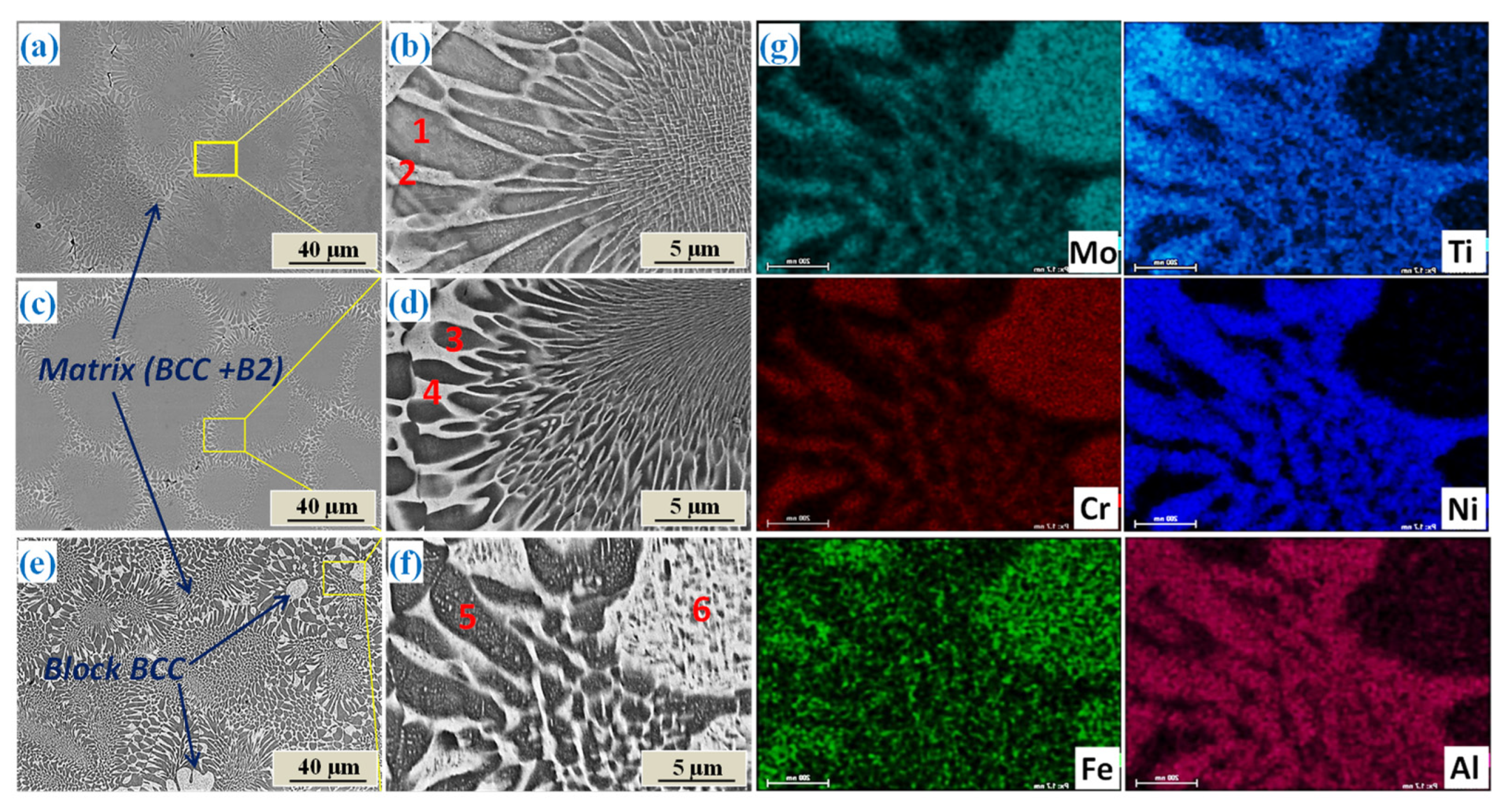
Figure 2 presents SEM backscattering micrographs of AlCrFeNiTi0.5, AlCrFeNiTi0.5Mo0.1, AlCrFeNiTi0.5Mo0.2 alloys. Magnified images are shown in Figure 2b,d,e. Chemical compositions of different regions in AlCrFeNiTi0.5Mox are summarized in Table 1. The SEM images of AlCrFeNiTi0.5 and AlCrFeNiTi0.5Mo0.1 alloys show a flower-like morphology, which has alternating bright and dark phases (Figure 2a–d). According to Table 1, the bright domain is Fe-Cr enriched, which is the disordered BCC phase. The dark domain is Ni-Al-Ti enriched, which is thus the ordered B2 phase. The added Mo is mainly incorporated in the bright BCC phase. The findings are in agreement with the XRD results, which confirm the enrichment of Mo in the BCC phase and Ti in B2 phase. When the Mo molar ratio increased to 0.2, the SEM images (Figure 2e,f) show an additional bright block region with a size range of 8–12 μm. In combination with elemental maps (Figure 2g) and the EDS results (Table 1), the bright block region and the bright domain in the flower-like regions show identical composition with enriched Fe, Cr, and Mo, indicating they are the disordered BCC phase. The dark domain is rich in Ni, Al, and Ti and depleted in Mo element, indicating that Mo does not stay inside the ordered B2 phase.
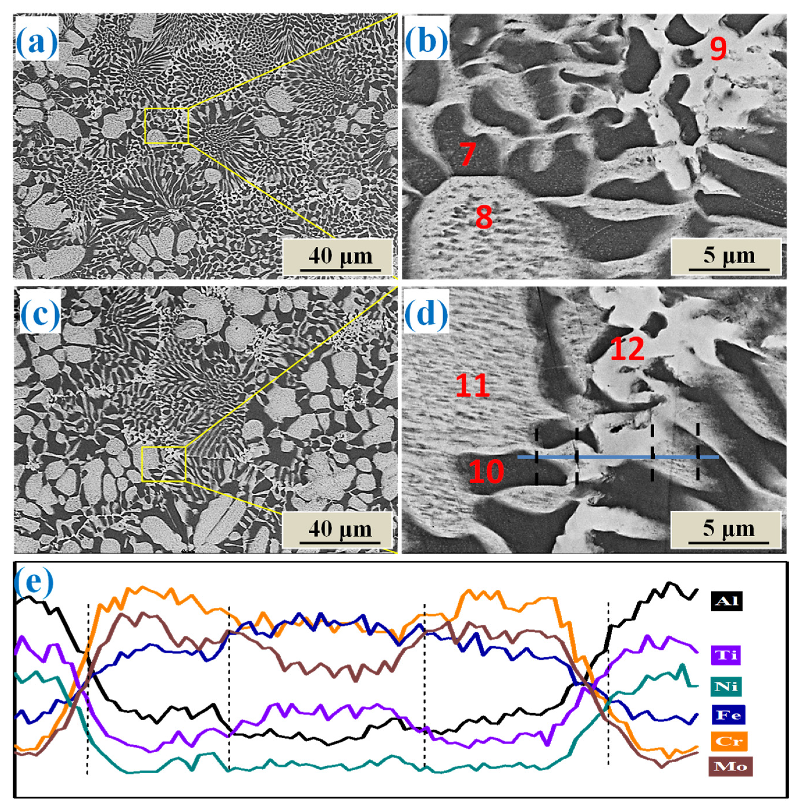
When Mo molar ratio was further increased to 0.3 and 0.4 (as shown in Figure 3a–d, there are three distinctive regions, which are alternating BCC + B2 region, bright block region (coarsen BCC phase), and the brightest precipitate at the grain boundary. With increasing the Mo addition, the fraction of coarsened BCC phase becomes larger and larger with its Mo content reaching 12.7 at. % and 13.9 at. % in samples T5M3 and T5M4, respectively. The brightest precipitate along the grain boundaries is also the disordered BCC phase but its solubilized elements are somewhat different. Results of EDS line scan analysis across the brightest BCC phase to the normal BCC region are shown in Figure 3e. The composition gradient near the interface is obvious for Mo and Ti. According to the results of EDS points’ analysis shown in Table 1, the brightest BCC domains are enriched with both Mo and Ti. It is known that Ti is mainly incorporated in the NiAl-rich B2 phase, due to large negative mixing enthalpy for Ti, Ni, and Al, whereas Mo is mainly in the disordered Fe-Cr-rich BCC phase. However, the BCC precipitates at grain boundaries are different, in which both Mo and Ti simultaneously enriched. This could be related to the fact that the grain boundary has higher strain energy, making it more attractive and able to accommodate impurity atoms and phases.

3.3. Mechanical Properties

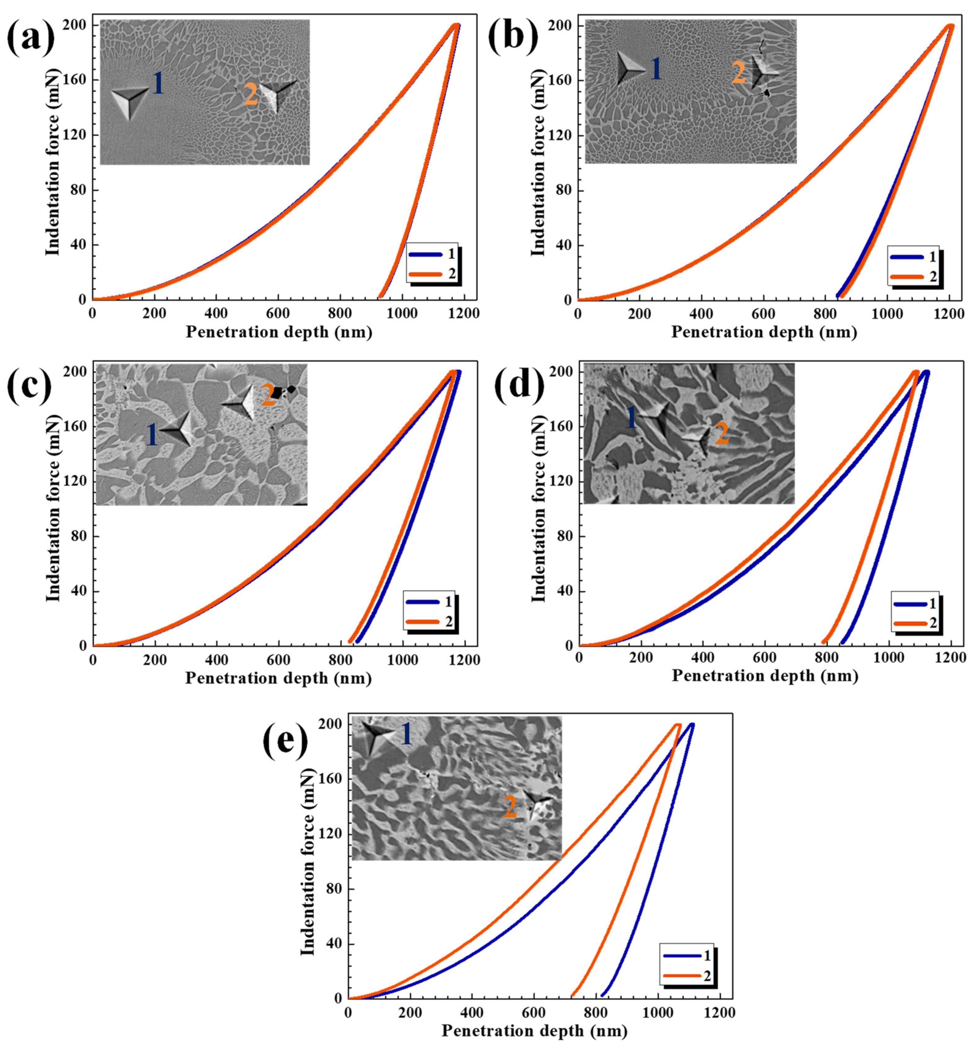
Nano-indentation tests were performed in specific regions to investigate the effect of Mo on local hardness related to microstructure features. Typical indentation tests on block BCC, (Mo, Ti)-rich BCC, and the region with alternating BCC & B2 in AlCrFeNiTi0.5Mox are shown in Figure 4. Values of micro-hardness and overall hardness are given in Table 2. As shown in Figure 4a,b, relatively homogeneous microstructure can be seen in AlCrFeNiTi0.5 and AlCrFeNiTi0.5Mo0.1 alloys, in which the alternated BCC and B2 phases form a compact network structure. The indenter covered the BCC + B2 domain, so that hardness of individual phase could not be measured. However, comparison between micro-hardness of grain and that of grain boundary can be made. As shown in Table 2, the Mo addition markedly increase the micro-hardness and overall hardness of AlCrFeNiTi0.5. Because the added Mo was mainly incorporated in the BCC phase, which strengthened the BCC phase by solution hardening and consequently contributed to the overall hardness of the AlCrFeNiTi0.5Mox alloy. With increasing the Mo molar ratio, the hardness was further increased. Comparing micro-hardness of the alternating BCC + B2 with that of block BCC, the former is 8571.8 MPa whereas the latter is 8831.8 MPa, indicating that the BCC phase in the Mo-added alloy, AlCrFeNiTi0.5Mo0.2, is slightly harder than the B2 phase.
With further increasing Mo content, the (Mo, Ti)-rich BCC phase at grain boundaries shows great superiority in hardness (Figure 4d,e). In addition, the multi-element phase could be fine in size due to the sluggish diffusion of atoms in the multi-element lattice [3,46]. On the whole, the bulk hardness of HEAs gradually increased from 752.5 to 989.7 HV0.5 as Mo molar ratio was increased from 0 to 0.4. For more information about the effect of Mo addition on mechanical properties of the alloy, compressive tests were performed. Results of the compressive tests are illustrated in Figure 5.
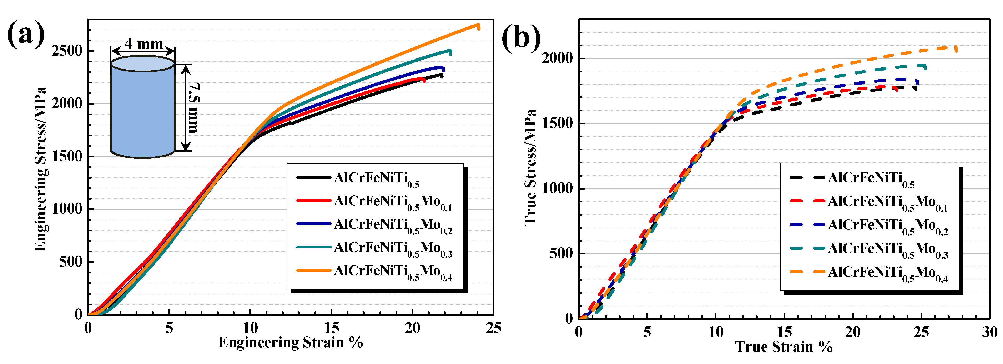
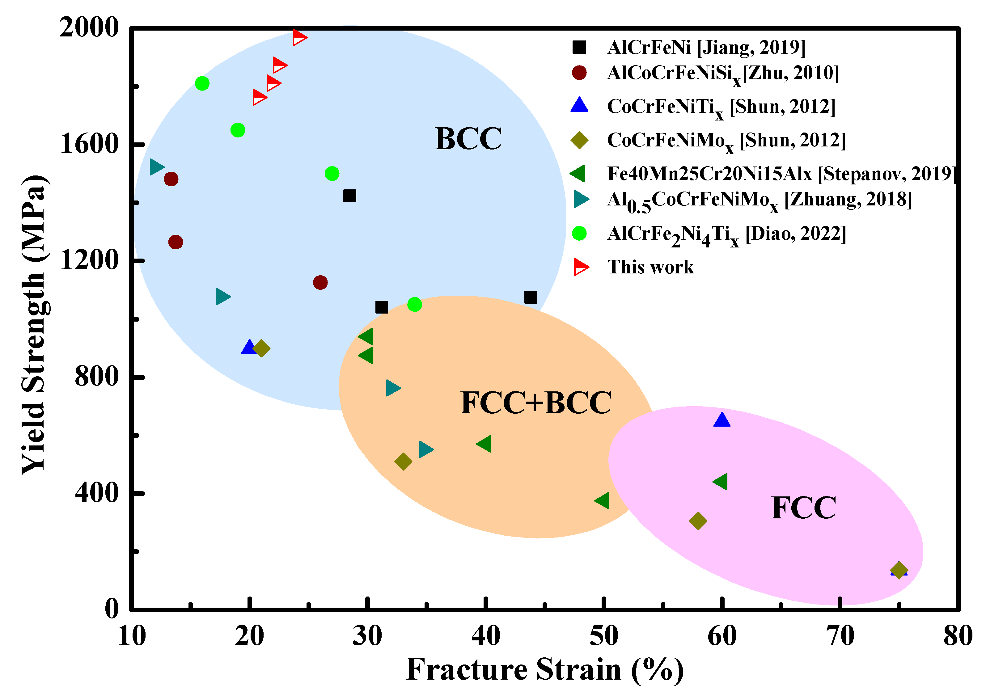
Figure 5 illustrates engineering compressive stress–strain curves of AlCrFeNiTi0.5Mox (x = 0–0.4) HEAs. Corresponding values of the compressive yield strength, maximum or fracture strength and fracture strain are summarized in Table 3. As shown, with the Mo addition, the yield strength increased from 1709 up to 1969 MPa, and the fracture strength increased from 2275 up to 2751 MPa. It is of particular interest to note that the Mo addition not only increased the strengths but also increased the fracture strain from 21.8% to 24.1%. Figure 6 shows the mechanical properties of the AlCrFeNiTi0.5Mox alloy in comparison with those of other as-cast HEAs reported in the literature [32,43,44,47,48,49,50]. One may see that almost all the strengthened alloy systems by solid-solution strengthening or precipitate hardening are always accompanied with obviously reduced ductility. In other words, the Mo addition helped achieve increases in both strength and ductility, but other as cast HEAs cannot achieve. The mechanism for the simultaneously increased strength and ductility of the Mo-added HEA, AlCrFeNiTi0.5Mox (x = 0–0.4), is discussed in Section 4.

3.4. Wear Resistance

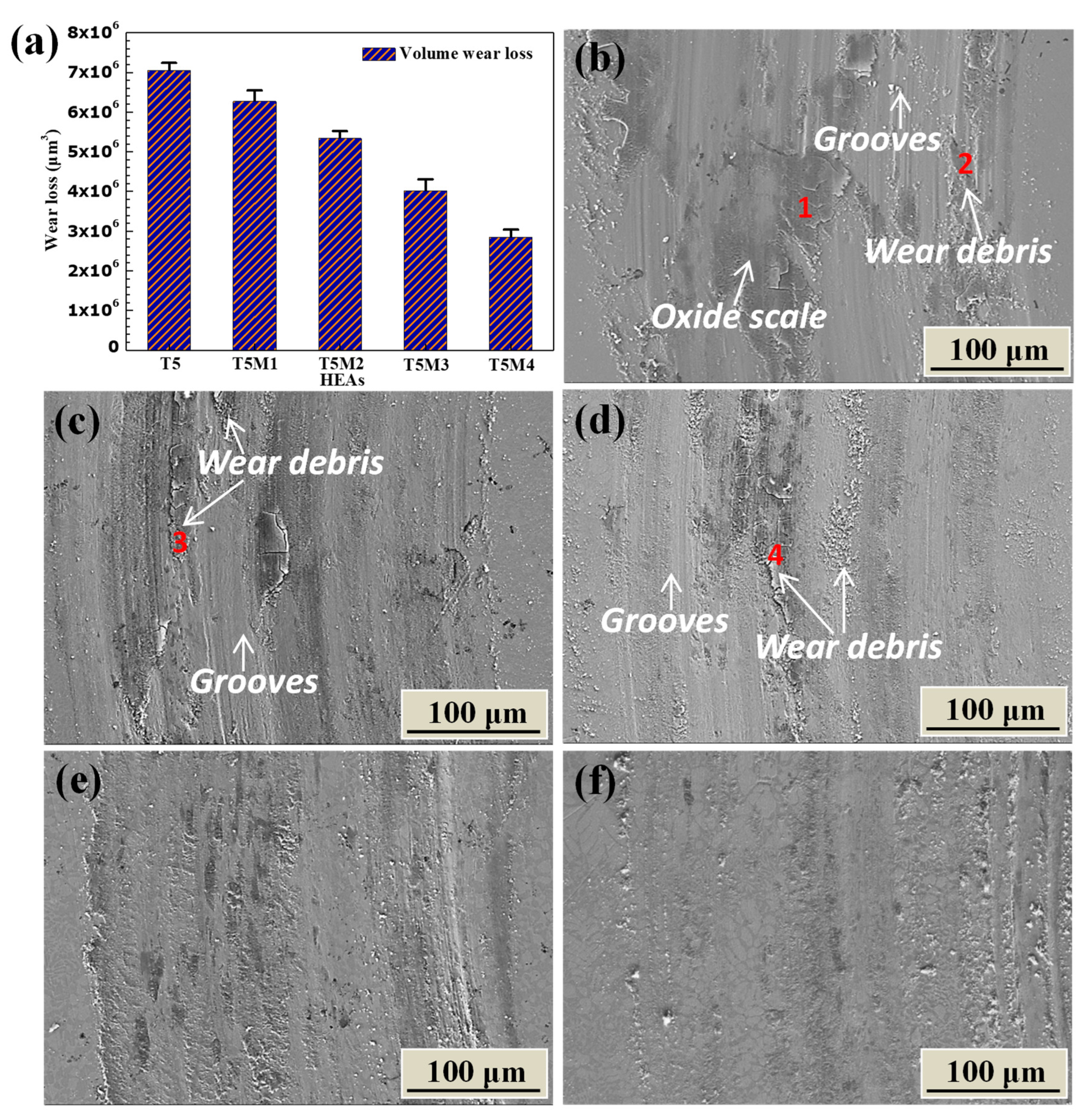
The resistance of AlCrFeNiTi0.5Mox HEAs to sliding wear against Si3N4 ball was evaluated by using a pin-on-disc tester. Figure 7a illustrates volume losses of AlCrFeNiTi0.5Mox with different Mo contents caused by wear over a sliding distance of 45 m. As shown, the volume loss is markedly reduced by the Mo addition. The Mo-free AlCrFeNiTi0.5 (7.05 × 106 μm3) has its volume loss about 2.5 times as large as that of AlCrFeNiTi0.5Mo0.4 (2.85 × 106 μm3). Worn surfaces of AlCrFeNiTi0.5Mox samples are illustrated in Figure 7b–f. For AlCrFeNiTi0.5 (Figure 7b), the worn surface is locally grooved without much ductile deformation. Patches are observed on the worn surface of AlCrFeNiTi0.5 alloy, some of which have been cracked or flaked off. There is a high amount of oxygen in the patches, indicating that oxidation occurred during the wear test with the formation of an oxide scale (Table 4). When the molar fraction of Mo is increased to 0.1 and 0.2, oxide debris rather than oxide patches are detected on the wear tracks (Figure 7c,d). There are still grooves formed by micro-plowing on the worn surface. For AlCrFeNiTi0.5Mo0.3 and AlCrFeNiTi0.5Mo0.4 alloys, little oxide debris is observed on the wear track and the grooves are considerably reduced with the addition of Mo.
To better understand the wear behavior of the HEAs, three-dimensional morphologies and cross-section profiles of wear scars are displayed in Figure 8. The color in the figure represents the depth of wear track as illustrated in Figure 8a–e. AlCrFeNiTi0.5 alloy shows grooves on the wear track (Figure 8a), which has a maximum depth of 7.9 μm and a maximum width of 295.6 μm (Figure 8f). With an increase in the Mo content, both the depth and width of wear track decrease. AlCrFeNiTi0.5Mo0.4 alloy has the smallest depth (3.2 μm) and width (259.7 μm) among all samples, demonstrating the highest wear resistance.

4. Discussion

4.1. Mo Distribution and Phase Prediction

In previous studies, the coexistence of Fe-Cr-rich disordering BCC phase (BCC) and NiAl-rich ordered BCC phase (B2) was observed in Co-free AlCrFeNi HEA. The Ti element increased the yield strength and hardness of the AlCrFeNi alloy due to the fact that Ti stayed in the Ni-Al rich ordered B2 phase, leading to the locally distorted lattice with enhanced capability to pin dislocations [32,34,37]. The mixing enthalpy of binary atom pairs [51] reveals considerably larger negative mixing enthalpy among Ni, Al, and Ti, which facilitates the formation of strengthened Ni-Al-Ti rich B2 phase. However, when Ti content exceeds a certain level (x > 0.5), a brittle Laves phase forms, which lowers the toughness and wear resistance of the alloy [37,38]. To mitigate the loss of toughness, in this study on AlCrFeNiTi0.5 alloy, we considered the addition of appropriate elements for the following possibilities: (1) they retain the high-strength BCC + B2 structure, (2) they do not interfere with the strengthening effect of Ti, (3) they reduce the interfacial mismatch between the disordered BCC phase and the ordered B2 phase, which helps reduce interfacial stress concentration and thus the probability of cracking.
As shown earlier, Mo preferentially stays in the disordered BCC phase. Thus, adding this element with a larger atomic size (atomic radius of Mo: 190 pm) may increase the lattice constant of the disordered BCC phase, bringing it closer to that of B2 phase. As a matter of fact, the lattice constants of the disordered BCC and ordered BCC (B2) phases are indeed closer as Mo is added (see XRD pattern shown in Figure 1). As demonstrated by the compressive tests, the Mo addition does improve the ductility with higher strength.
The simple duplex-BCC phase structure and the preferential incorporation of Mo in the disordered BCC phase could be explained or expected. Several parameters are used in reported studies to predict the stability of phases in HEAs [52,53,54,55,56]. For a multi-component HEA, ΔHmix (the element mixing enthalpy) and δ describe the chemical bond’s energy among different elements and the difference in atomic size between different elements, respectively. The two parameters are usually used to determine the formation of solid solutions [54,55]. Guo et al. [56] showed that the valence electron concentration, VEC, was also a good indicator of the stability of BCC and FCC phases. These parameters are expressed as
Δ H m i x = i = 1 , i j n 4 Δ H A B m i x c i c j
δ = i = 1 n c i ( 1 r i r ) 2
r = i = 1 n c i r i
V E C = i = 1 n c i ( V E C ) i ,
where ΔHmix and δ are the mixing enthalpy and the atomic size difference for atomic pairs in multi-components HEAs, respectively, Δ H A B m i x stands for the mixing enthalpy of elements A and B, ci and ri are the atomic percentage and radius of the ith element, respectively, and r is the average atomic radius. Table 5 lists the enthalpy of mixing for atomic pairs, atomic radius and VEC of elements in Al-Cr-Fe-Ni-Ti-Mo system. The calculated ΔHmix, δ and VEC are shown in Table 6.
Zhang et al. [55] showed that solid solutions were stable when −20 < ΔHmix < 5 kJ/mol and δ ≤ 6.6%, including disordered and ordered solid solutions. Larger negative mixing enthalpy means that the binding force between elements is larger, more favoring mixing of the elements. However, the positive mixing of enthalpy causes element segregations. For AlCrFeNiTi0.5, values of ΔHmix and δ are −19.22 kJ/mol and 7.11%, respectively (Table 6). Clearly, the δ is beyond the range of forming a solid solution. Our previous and present studies have revealed the coexistence of disordered BCC solid solution and ordered BCC (B2) phases in AlCrFeNiTi0.5 alloy. These results are consistent with the study by Zhang et al. [55] which, with a standard ΔHmix, a little increase in δ will deepen the extent of ordering, thus bringing out the precipitation of the ordered phase, except for the dominant solid solution. After adding Mo, values of ΔHmix, δ in AlCrFeNiTi0.5Mox (x = 0.1, 0.2, 0.3 and 0.4) are −18.73 ≤ ΔHmix ≤ −17.31 kJ/mol, and 6.87% ≤ δ ≤ 7.04%, where the ΔHmix is in the range of forming a solid solution and the δ is still a little higher than the standard range (δ ≤ 6.6%) although it is lower than that in AlCrFeNiTi0.5. Therefore, AlCrFeNiTi0.5Mox is expected to maintain the microstructure of disordered BCC solid solution plus the ordered B2 phase, similar to that of the AlCrFeNiTi0.5.
For prediction of BCC or FCC phase for HEAs, it is proposed that FCC would be the only phase present for alloys with VEC ≥ 8.0, and the BCC structure would be the only phase for alloys with VEC < 6.87. Intermediate VEC values would include a mixture of the two structures [56]. The values of VEC in AlCrFeNiTi0.5Mox (x = 0, 0.1, 0.2, 0.3 and 0.4) are 6.405 ≤ VEC ≤ 6.443 (Table 6), which fall into the region of stable BCC phase. The XRD results (Figure 1) have shown that AlCrFeNiTi0.5Mox alloys all have the disordered BCC phase (BCC) and ordered BCC phase (B2), indicating that the ΔHmix, δ, and VEC successfully predict the phase formation and structural stability of AlCrFeNiTi0.5 with Mo addition.
The addition of Mo has shown some interesting effects on microstructure, which is also related to the above parameters. Mo mainly acts as a solute in the Fe–Cr disordered BCC with minor influence on the NiAlTi ordered B2 phase. This can be predicted from the mixing enthalpy of binary atom pairs (Table 5). Mo has larger negative mixing enthalpies with NiAlTi (−7, −5 and −4 kJ/mol) than that with FeCr (−2 and 0 kJ/mol), but it mostly dissolves into the latter phase. This unexpected phenomenon could be attributed to the fact that the mixing enthalpy among Ni, Al, and Ti is significantly more negative than that for any other element pairs, thus facilitating the formation of the NiAlTi phase (B2) and blocking the incorporation of Mo into the B2 phase. As a result, Mo preferentially gets into the disordered BCC phase without influencing the B2 phase, hence helping minimize the mismatch of lattice constant between Fe–Cr and NiAlTi phase as illustrated in Figure 1.

4.2. Further Discussion on Mo Effects Mechanical Properties and Wear Resistance

In AlCrFeNiTi0.5 alloy, the lattice distortion caused by Ti in B2 phase leads to solid solution strengthening but enlarges the lattice mismatch between B2 and disordered BCC phase. When adding Mo to this alloy, the preferential incorporation of Mo into the disordered BCC phase increases its lattice cell size, thus (1) reducing the lattice mismatch between the disordered BCC phase and the B2 phase, and (2) strengthening the disordered BCC phase via solid solution-strengthening mechanism. As a result, the strengthened disordered BCC phase helps increase the overall hardness of the alloy. In the meanwhile, Mo increases the lattice constant of disordered BCC phase, gradually catching up with the enlarged one of B2 phase caused by Ti [45]. The reduced lattice mismatch consequently makes the interface between the disordered BCC phase and the B2 phase coincident, which reduces the interfacial stress and thus minimizes the probability of interfacial failure caused by excessive dislocation build-up, leading to improved toughness [57] and ductility as illustrated by Figure 5.
With further increasing the Mo addition, in addition to the strengthened disordered BCC phase, the precipitation of a new type or modified BCC phase at the grain boundary also strengthens the alloy, which is a Fe–Cr phase enriched with both Mo and Ti as shown in (Figure 3 and Figure 4). AlCrFeNiTi0.5Mo0.3 and AlCrFeNiTi0.5Mo0.4 alloys are strengthened by Mo-solute strengthening of the disordered BCC phase and the precipitation at grain boundary. The increases in both strength and ductility are largely responsible for the considerably increased wear resistance, as Figure 7 illustrates.
In general, the wear resistance of an alloy depends on its mechanical strength and ductility, both of which determine the alloy’s toughness. However, during wear in ambient environment, the frictional heat-induced oxide scale may also affect the wear resistance. As shown in Figure 7, the oxide can be seen in some areas on the worn surfaces. To obtain the information on the role of the oxide scale in resisting wear, another set of wear tests were conducted with an air flow directed to the contacting area between sample and the counterpart to eliminate the frictional heating effect, thereby minimizing the influence of oxidation on wear. Figure 9 shows volume losses of the samples tested with and without the air flow. As illustrated, the volume loss of AlCrFeNiTi0.5 was slightly increased when air flow was introduced, indicating that the oxide scales resulting from the frictional heat benefit the wear resistance to some extent. The wear mechanism for AlCrFeNiTi0.5 is mainly abrasive wear accompanied with some oxidation. However, for the Mo-containing alloy, there is a mild decrease in volume loss with the air flow cooling. In this case, the oxidation did not much influence the wear performances of the samples, and abrasive wear is the main wear mechanism for AlCrFeNiTi0.5Mox [58]. The little or minor difference in volume loss between Mo-containing samples tested with or without the air flow indicates that the improvement in the wear resistance by the Mo addition primarily comes from its benefits to the alloy’s strength, ductility, and toughness.

5. Conclusions

Microstructure, mechanical properties, and wear resistance of Mo-containing high-entropy alloy, AlCrFeNiTi0.5Mox (x = 0.1–0.4), were investigated in comparison with those of Mo-free AlCrFeNiTi0.5 alloy. The following conclusions are drawn:
(1)
The as-cast AlCrFeNiTi0.5Mox alloys all consisted of a Fe–Cr-rich, disordered BCC phase and a NiAl-rich, ordered BCC phase (B2). The added Mo mainly stayed and acted a solid solute in the BCC phase, strengthening the phase. When Mo molar ratio was more than 0.3, a modified BCC phase formed at the grain boundary, which was enriched with both Mo and Ti.
(2)
The Mo addition markedly increased the strength and ductility of AlCrFeNiTi0.5 alloy. The increase in strength was mainly caused by Mo-strengthened disordered BCC phase and precipitation-strengthening by hard (Mo, Ti)-rich BCC precipitates at grain boundaries. The improved ductility benefited from the reduced interfacial lattice mismatch between the disordered BCC phase and B2 phase.
(3)
The Mo-free AlCrFeNiTi0.5 showed the largest wear volume loss, which was about 2.5 times as large as that of AlCrFeNiTi0.5Mo0.4 due to its lower yield strength, fracture strength, and ductility. The AlCrFeNiTi0.5Mo0.4 alloy showed the lowest wear volume loss, which possessed the highest values of all the above mentioned three mechanical properties.

Author Contributions

Conceptualization, M.W. and D.L.; methodology, M.W. and J.Y.; validation, M.W., J.Y. and G.D.; formal analysis, M.W.; investigation, M.W. and J.Y.; resources, M.W. and G.D.; data curation, M.W. and D.L.; writing—original draft preparation, M.W.; writing—review and editing, D.L.; visualization, M.W.; supervision, D.L. All authors have read and agreed to the published version of the manuscript.

Funding

The authors are grateful for financial support from the Natural Science and Engineering Research Council of Canada (ALLRP 567506-21 Li, ALLRP 561172-20 Li), Alberta Innovates (AB Innovates ADVANCE 202102824 L), Trimay, and Mitacs.

Data Availability Statement

The paper is self-containing. For additional information or data, please contact the corresponding author.

Conflicts of Interest

The authors declare no conflict of interest.

References

  1. Miracle, D.B.; Senkov, O.N. A critical review of high entropy alloys and related concepts. Acta Mater. 2017, 122, 448–511. [Google Scholar] [CrossRef] [Green Version]
  2. Tsai, M.-H. Three Strategies for the Design of Advanced High-Entropy Alloys. Entropy 2016, 18, 252. [Google Scholar] [CrossRef] [Green Version]
  3. Yeh, J.W.; Chen, S.K.; Lin, S.J.; Gan, J.Y.; Chin, T.S.; Shun, T.T.; Tsau, C.H.; Chang, S.Y. Nanostructured High-Entropy Alloys with Multiple Principal Elements: Novel Alloy Design Concepts and Outcomes. Adv. Eng. Mater. 2004, 6, 299–303. [Google Scholar] [CrossRef]
  4. Cantor, B.; Chang, I.T.H.; Knight, P.; Vincent, A.J.B. Microstructural development in equiatomic multicomponent alloys. Mater. Sci. Eng. A 2004, 375–377, 213–218. [Google Scholar] [CrossRef]
  5. Tsai, M.-H.; Yeh, J.-W. High-Entropy Alloys: A Critical Review. Mater. Res. Lett. 2014, 2, 107–123. [Google Scholar] [CrossRef]
  6. Peighambardoust, N.S.; Alamdari, A.A.; Unal, U.; Motallebzadeh, A. In vitro biocompatibility evaluation of Ti1.5ZrTa0.5Nb0.5Hf0.5 refractory high-entropy alloy film for orthopedic implants: Microstructural, mechanical properties and corrosion behavior. J. Alloys Compd. 2021, 883, 160786. [Google Scholar] [CrossRef]
  7. Salishchev, G.A.; Tikhonovsky, M.A.; Shaysultanov, D.G.; Stepanov, N.D.; Kuznetsov, A.V.; Kolodiy, I.V.; Tortika, A.S.; Senkov, O.N. Effect of Mn and V on structure and mechanical properties of high-entropy alloys based on CoCrFeNi system. J. Alloys Compd. 2014, 591, 11–21. [Google Scholar] [CrossRef]
  8. Wang, W.-R.; Wang, W.-L.; Wang, S.-C.; Tsai, Y.-C.; Lai, C.-H.; Yeh, J.-W. Effects of Al addition on the microstructure and mechanical property of AlxCoCrFeNi high-entropy alloys. Intermetallics 2012, 26, 44–51. [Google Scholar] [CrossRef]
  9. Owen, L.R.; Jones, N.G. Lattice distortions in high-entropy alloys. J. Mater. Res. 2018, 33, 2954–2969. [Google Scholar] [CrossRef]
  10. Shim, S.H.; Pouraliakbar, H.; Lee, B.J.; Kim, Y.K.; Rizi, M.S.; Hong, S.I. Strengthening and deformation behavior of as-cast CoCrCu1.5MnNi high entropy alloy with micro-/nanoscale precipitation. Mater. Sci. Eng. A 2022, 853, 143729. [Google Scholar] [CrossRef]
  11. Saboktakin Rizi, M.; Minouei, H.; Lee, B.J.; Toroghinejad, M.R.; Hong, S.I. Effects of carbon and molybdenum on the nanostructural evolution and strength/ductility trade-off in Fe40Mn40Co10Cr10 high-entropy alloys. J. Alloys Compd. 2022, 911, 165108. [Google Scholar] [CrossRef]
  12. Pouraliakbar, H.; Shim, S.H.; Kim, Y.K.; Rizi, M.S.; Noh, H.; Hong, S.I. Microstructure evolution and mechanical properties of (CoCrNi)90(AlTiZr)5(CuFeMo)5 multicomponent alloy: A pathway through multicomponent alloys toward new superalloys. J. Alloys Compd. 2021, 860, 158412. [Google Scholar] [CrossRef]
  13. Yeh, J.-W. Alloy Design Strategies and Future Trends in High-Entropy Alloys. JOM 2013, 65, 1759–1771. [Google Scholar] [CrossRef]
  14. Zhang, Z.; Armstrong, D.E.J.; Grant, P.S. The effects of irradiation on CrMnFeCoNi high-entropy alloy and its derivatives. Prog. Mater. Sci. 2022, 123, 100807. [Google Scholar] [CrossRef]
  15. Liu, Y.; Zhang, F.; Huang, Z.; Zhou, Q.; Ren, Y.; Du, Y.; Wang, H. Mechanical and dry sliding tribological properties of CoCrNiNbx medium-entropy alloys at room temperature. Tribol. Int. 2021, 163, 107160. [Google Scholar] [CrossRef]
  16. Ye, F.; Jiao, Z.; Yan, S.; Guo, L.; Feng, L.; Yu, J. Microbeam plasma arc remanufacturing: Effects of Al on microstructure, wear resistance, corrosion resistance and high temperature oxidation resistance of AlxCoCrFeMnNi high-entropy alloy cladding layer. Vacuum 2020, 174, 109178. [Google Scholar] [CrossRef]
  17. Sun, S.J.; Tian, Y.Z.; Lin, H.R.; Yang, H.J.; Dong, X.G.; Wang, Y.H.; Zhang, Z.F. Achieving high ductility in the 1.7 GPa grade CoCrFeMnNi high-entropy alloy at 77 K. Mater. Sci. Eng. A 2019, 740–741, 336–341. [Google Scholar] [CrossRef]
  18. Sun, S.J.; Tian, Y.Z.; Lin, H.R.; Lu, S.; Yang, H.J.; Zhang, Z.F. Modulating the prestrain history to optimize strength and ductility in CoCrFeMnNi high-entropy alloy. Scr. Mater. 2019, 163, 111–115. [Google Scholar] [CrossRef]
  19. Wang, Z.; Baker, I.; Guo, W.; Poplawsky, J.D. The effect of carbon on the microstructures, mechanical properties, and deformation mechanisms of thermo-mechanically treated Fe40.4Ni11.3Mn34.8Al7.5Cr6 high entropy alloys. Acta Mater. 2017, 126, 346–360. [Google Scholar] [CrossRef] [Green Version]
  20. Qiu, Y.; Hu, Y.J.; Taylor, A.; Styles, M.J.; Marceau, R.K.W.; Ceguerra, A.V.; Gibson, M.A.; Liu, Z.K.; Fraser, H.L.; Birbilis, N. A lightweight single-phase AlTiVCr compositionally complex alloy. Acta Mater. 2017, 123, 115–124. [Google Scholar] [CrossRef]
  21. Feng, R.; Gao, M.C.; Lee, C.; Mathes, M.; Zuo, T.; Chen, S.; Hawk, J.A.; Zhang, Y.; Liaw, P.K. Design of Light-Weight High-Entropy Alloys. Entropy 2016, 18, 333. [Google Scholar] [CrossRef] [Green Version]
  22. Du, C.; Hu, L.; Pan, Q.; Chen, K.; Zhou, P.; Wang, G. Effect of Cu on the strengthening and embrittling of an FeCoNiCr-xCu HEA. Mater. Sci. Eng. A 2022, 832, 142413. [Google Scholar] [CrossRef]
  23. Tsau, C.-H.; Lin, S.-X.; Fang, C.-H. Microstructures and corrosion behaviors of FeCoNi and CrFeCoNi equimolar alloys. Mater. Chem. Phys. 2017, 186, 534–540. [Google Scholar] [CrossRef]
  24. Liu, B.; Wang, J.; Liu, Y.; Fang, Q.; Wu, Y.; Chen, S.; Liu, C.T. Microstructure and mechanical properties of equimolar FeCoCrNi high entropy alloy prepared via powder extrusion. Intermetallics 2016, 75, 25–30. [Google Scholar] [CrossRef]
  25. Zeng, Z.; Xiang, M.; Zhang, D.; Shi, J.; Wang, W.; Tang, X.; Tang, W.; Wang, Y.; Ma, X.; Chen, Z.; et al. Mechanical properties of Cantor alloys driven by additional elements: A review. J. Mater. Res. Technol. 2021, 15, 1920–1934. [Google Scholar] [CrossRef]
  26. Cantor, B. Multicomponent high-entropy Cantor alloys. Prog. Mater. Sci. 2021, 120, 100754. [Google Scholar] [CrossRef]
  27. Chen, S.; Oh, H.S.; Gludovatz, B.; Kim, S.J.; Park, E.S.; Zhang, Z.; Ritchie, R.O.; Yu, Q. Real-time observations of TRIP-induced ultrahigh strain hardening in a dual-phase CrMnFeCoNi high-entropy alloy. Nat. Commun. 2020, 11, 826. [Google Scholar] [CrossRef] [Green Version]
  28. Wang, H.; Chen, D.; An, X.; Zhang, Y.; Sun, S.; Tian, Y.; Zhang, Z.; Wang, A.; Liu, J.; Song, M.; et al. Deformation-induced crystalline-to-amorphous phase transformation in a CrMnFeCoNi high-entropy alloy. Sci. Adv. 2021, 7, eabe3105. [Google Scholar] [CrossRef]
  29. Wang, S.; Chen, L.; Li, Q.; Wang, S.; Wu, M.; Yang, S.; Xiang, D. Effects of Al or Mo Addition on Microstructure and Mechanical Properties of Fe-Rich Nonequiatomic FeCrCoMnNi High-Entropy Alloy. Metals 2022, 12, 191. [Google Scholar] [CrossRef]
  30. Chuang, M.-H.; Tsai, M.-H.; Wang, W.-R.; Lin, S.-J.; Yeh, J.-W. Microstructure and wear behavior of AlxCo1.5CrFeNi1.5Tiy high-entropy alloys. Acta Mater. 2011, 59, 6308–6317. [Google Scholar] [CrossRef]
  31. Tian, L.; Jiao, Z.M.; Yuan, G.Z.; Ma, S.G.; Wang, Z.H.; Yang, H.J.; Zhang, Y.; Qiao, J.W. Effect of Strain Rate on Deformation Behavior of AlCoCrFeNi High-Entropy Alloy by Nanoindentation. J. Mater. Eng. Perform. 2016, 25, 2255–2260. [Google Scholar] [CrossRef]
  32. Jiang, Z.; Chen, W.; Xia, Z.; Xiong, W.; Fu, Z. Influence of synthesis method on microstructure and mechanical behavior of Co-free AlCrFeNi medium-entropy alloy. Intermetallics 2019, 108, 45–54. [Google Scholar] [CrossRef]
  33. Wu, M.; Setiawan, R.C.; Li, D.Y. Benefits of passive element Ti to the resistance of AlCrFeCoNi high-entropy alloy to corrosion and corrosive wear. Wear 2022, 492–493, 204231. [Google Scholar] [CrossRef]
  34. Wu, M.; Chen, K.; Xu, Z.; Li, D.Y. Effect of Ti addition on the sliding wear behavior of AlCrFeCoNi high-entropy alloy. Wear 2020, 462–463, 203493. [Google Scholar] [CrossRef]
  35. Chen, Z.; Chen, W.; Wu, B.; Cao, X.; Liu, L.; Fu, Z. Effects of Co and Ti on microstructure and mechanical behavior of Al0.75FeNiCrCo high entropy alloy prepared by mechanical alloying and spark plasma sintering. Mater. Sci. Eng. A 2015, 648, 217–224. [Google Scholar] [CrossRef]
  36. Fu, Z.; Chen, W.; Chen, Z.; Wen, H.; Lavernia, E.J. Influence of Ti addition and sintering method on microstructure and mechanical behavior of a medium-entropy Al0.6CoNiFe alloy. Mater. Sci. Eng. A 2014, 619, 137–145. [Google Scholar] [CrossRef]
  37. Li, S.; Chen, F.; Tang, X.; Ge, G.; Sun, Z.; Geng, Z.; Fan, M.; Huang, P. Effect of Ti on the Microstructure and Mechanical Properties of AlCrFeNiTix Eutectic High-Entropy Alloys. J. Mater. Eng. Perform. 2022. [Google Scholar] [CrossRef]
  38. Löbel, M.; Lindner, T.; Mehner, T.; Lampke, T. Influence of Titanium on Microstructure, Phase Formation and Wear Behaviour of AlCoCrFeNiTix High-Entropy Alloy. Entropy 2018, 20, 505. [Google Scholar] [CrossRef] [Green Version]
  39. Zhao, Y.; Zhang, X.; Quan, H.; Chen, Y.; Wang, S.; Zhang, S. Effect of Mo addition on structures and properties of FeCoNiCrMn high entropy alloy film by direct current magnetron sputtering. J. Alloys Compd. 2022, 895, 162709. [Google Scholar] [CrossRef]
  40. Hsu, W.-C.; Kao, W.-P.; Yeh, J.-W.; Tsai, C.-W. Effect of Mo on the Mechanical and Corrosion Behaviors in Non-Equal Molar AlCrFeMnNi BCC High-Entropy Alloys. Mater. Sci. Mater. Rev. 2022, 15, 751. [Google Scholar] [CrossRef]
  41. Liu, Y.; Xie, Y.; Cui, S.; Yi, Y.; Xing, X.; Wang, X.; Li, W. Effect of Mo Element on the Mechanical Properties and Tribological Responses of CoCrFeNiMox High-Entropy Alloys. Metals 2021, 11, 468. [Google Scholar] [CrossRef]
  42. Qin, G.; Chen, R.; Zheng, H.; Fang, H.; Wang, L.; Su, Y.; Guo, J.; Fu, H. Strengthening FCC-CoCrFeMnNi high entropy alloys by Mo addition. J. Mater. Sci. Technol. 2019, 35, 578–583. [Google Scholar] [CrossRef]
  43. Zhuang, Y.-X.; Zhang, X.-L.; Gu, X.-Y. Effect of Annealing on Microstructure and Mechanical Properties of Al0.5CoCrFeMoxNi High-Entropy Alloys. Entropy 2018, 20, 812. [Google Scholar] [CrossRef] [Green Version]
  44. Shun, T.-T.; Chang, L.-Y.; Shiu, M.-H. Microstructure and mechanical properties of multiprincipal component CoCrFeNiMox alloys. Mater. Charact. 2012, 70, 63–67. [Google Scholar] [CrossRef]
  45. Yu, Y.; Wang, J.; Li, J.; Kou, H.; Liu, W. Characterization of BCC phases in AlCoCrFeNiTix high entropy alloys. Mater. Lett. 2015, 138, 78–80. [Google Scholar] [CrossRef]
  46. Yeh, J.-W. Recent progress in high-entropy alloys. Eur. J. Control 2006, 31, 633–648. [Google Scholar] [CrossRef]
  47. Zhu, J.M.; Fu, H.M.; Zhang, H.F.; Wang, A.M.; Li, H.; Hu, Z.Q. Synthesis and properties of multiprincipal component AlCoCrFeNiSix alloys. Mater. Sci. Eng. A 2010, 527, 7210–7214. [Google Scholar] [CrossRef]
  48. Shun, T.-T.; Chang, L.-Y.; Shiu, M.-H. Microstructures and mechanical properties of multiprincipal component CoCrFeNiTix alloys. Mater. Sci. Eng. A 2012, 556, 170–174. [Google Scholar] [CrossRef]
  49. Stepanov, N.D.; Shaysultanov, D.G.; Chernichenko, R.S.; Tikhonovsky, M.A.; Zherebtsov, S.V. Effect of Al on structure and mechanical properties of Fe-Mn-Cr-Ni-Al non-equiatomic high entropy alloys with high Fe content. J. Alloys Compd. 2019, 770, 194–203. [Google Scholar] [CrossRef] [Green Version]
  50. Diao, G.; He, A.; Li, D.Y.; Wu, M.; Xu, Z.; Li, W.; Li, Q.Y. Tune a highly ductile AlCrFe2Ni4 alloy by Ti addition for desired high mechanical strength. Mater. Sci. Eng. A 2022, 856, 143910. [Google Scholar] [CrossRef]
  51. Takeuchi, A.; Inoue, A. Classification of Bulk Metallic Glasses by Atomic Size Difference, Heat of Mixing and Period of Constituent Elements and Its Application to Characterization of the Main Alloying Element. Mater. Trans. 2005, 46, 2817–2829. [Google Scholar] [CrossRef] [Green Version]
  52. Wang, Z.; Huang, Y.; Yang, Y.; Wang, J.; Liu, C.T. Atomic-size effect and solid solubility of multicomponent alloys. Scr. Mater. 2015, 94, 28–31. [Google Scholar] [CrossRef]
  53. Singh, A.K.; Kumar, N.; Dwivedi, A.; Subramaniam, A. A geometrical parameter for the formation of disordered solid solutions in multi-component alloys. Intermetallics 2014, 53, 112–119. [Google Scholar] [CrossRef]
  54. Yang, X.; Zhang, Y. Prediction of high-entropy stabilized solid-solution in multi-component alloys. Mater. Chem. Phys. 2012, 132, 233–238. [Google Scholar] [CrossRef]
  55. Zhang, Y.; Zhou, Y.J.; Lin, J.P.; Chen, G.L.; Liaw, P.K. Solid-Solution Phase Formation Rules for Multi-component Alloys. Adv. Eng. Mater. 2008, 10, 534–538. [Google Scholar] [CrossRef]
  56. Guo, S.; Ng, C.; Lu, J.; Liu, C.T. Effect of valence electron concentration on stability of fcc or bcc phase in high entropy alloys. J. Appl. Phys. 2011, 109, 103505. [Google Scholar] [CrossRef] [Green Version]
  57. Fan, L.; Yang, T.; Zhao, Y.; Luan, J.; Zhou, G.; Wang, H.; Jiao, Z.; Liu, C.-T. Ultrahigh strength and ductility in newly developed materials with coherent nanolamellar architectures. Nat. Commun. 2020, 11, 6240. [Google Scholar] [CrossRef]
  58. Wang, S.D.; Wu, M.Y.; Xu, D.K.; Han, E.-h. Improving corrosive wear resistance of Mg-Zn-Y-Zr alloys through heat treatment. J. Magnes. Alloys 2021. [Google Scholar] [CrossRef]
Figure 1. X-ray diffraction patterns of AlCrFeNiTi0.5, AlCrFeNiTi0.5Mo0.1, AlCrFeNiTi0.5Mo0.2, AlCrFeNiTi0.5Mo0.3, and AlCrFeNiTi0.5Mo0.4 HEAs.
Metals 12 01910 g001
Figure 2. SEM backscattering electron micrographs of (a,b) AlCrFeNiTi0.5, (c,d) AlCrFeNiTi0.5Mo0.1, (e,f) AlCrFeNiTi0.5Mo0.2 HEAs. (b,d,f) High-magnification images of areas marked by yellow squares in image (a,c,e,g). EDS elemental maps of various elements in AlCrFeNiTi0.5Mo0.2 HEA, whose SEM image is shown in (f).
Metals 12 01910 g002
Figure 3. SEM backscattering electron micrographs of (a,b) AlCrFeNiTi0.5Mo0.3, (c,d) AlCrFeNiTi0.5Mo0.4 HEAs. (b,d) Magnified images of the regions marked by yellow squares in images (a,c). (e) Line scans analysis of the interface between brightest precipitate and adjacent BCC phase in AlCrFeNiTi0.5Mo0.4 HEA shown in (d).
Metals 12 01910 g003
Figure 4. Representative indentation images and corresponding load-displacement curves for (a) AlCrFeNiTi0.5, (b) AlCrFeNiTi0.5Mo0.1, (c) AlCrFeNiTi0.5Mo0.2, (d) AlCrFeNiTi0.5Mo0.3, and (e) AlCrFeNiTi0.5Mo0.4 samples.
Metals 12 01910 g004
Figure 5. (a) Engineering stress–strain curves and (b) true stress–strain curves of compression tests for the HEA samples.
Metals 12 01910 g005
Figure 6. Property comparison between AlCrFeNiTi0.5Mox and other HEAs reported in the literature with emphasis on the yield strength and fracture strain [32,43,44,47,48,49,50].
Metals 12 01910 g006
Figure 7. (a) Wear volume loss of AlCrFeNiTi0.5Mox over a sliding distance of 45 m, and corresponding SEM micrographs of worn surfaces. (b) AlCrFeNiTi0.5, (c) AlCrFeNiTi0.5Mo0.1, (d) AlCrFeNiTi0.5Mo0.2, (e) AlCrFeNiTi0.5Mo0.3, and (f) AlCrFeNiTi0.5Mo0.4, respectively.
Metals 12 01910 g007
Figure 8. Three-dimensional images of wear scars on five samples after wear tests over a sliding distance of 45 m. (a) AlCrFeNiTi0.5, (b) AlCrFeNiTi0.5Mo0.1, (c) AlCrFeNiTi0.5Mo0.2, (d) AlCrFeNiTi0.5Mo0.3, and (e) AlCrFeNiTi0.5Mo0.4 alloys. (f) Cross-sectional profiles of wear tracks on the five samples.
Metals 12 01910 g008
Figure 9. Wear volume loss of AlCrFeNiTi0.5Mox over a sliding distance of 45 m with and without air flow.
Metals 12 01910 g009
Table 1. Compositions (at. %) of different regions in AlCrFeNiTi0.5Mox alloys.
AlloysAreasAlCrFeNiTiMo
AlCrFeNiTi0.5126.06.117.128.622.2/
29.639.937.55.97.1/
AlCrFeNiTi0.5Mo0.1324.65.417.029.522.90.5
45.940.841.92.34.84.3
AlCrFeNiTi0.5Mo0.2528.810.817.627.513.61.7
611.041.029.06.24.410.4
AlCrFeNiTi0.5Mo0.3724.84.914.933.221.21.1
811.236.126.56.66.712.7
95.926.839.26.912.78.4
AlCrFeNiTi0.5Mo0.41025.14.114.133.921.90.9
1113.431.324.010.37.013.9
126.321.636.19.115.911.1
Table 2. Local micro-hardness and overall hardness of AlCrFeNiTi0.5Mox HEAs.
Alloys RegionsMicro-Hardness (MPa)Overall Hardness (HV)
AlCrFeNiTi0.51 (BCC + B2)7557.4752.5
2 (BCC + B2)7624.5
AlCrFeNiTi0.5Mo0.11 (BCC + B2)8336.1829.2
2 (BCC + B2)8320.5
AlCrFeNiTi0.5Mo0.21 (BCC + B2)8571.8876.3
2 Block BCC8831.8
AlCrFeNiTi0.5Mo0.31 (BCC + B2)9015.1943.6
2 (Mo, Ti)-rich BCC9830.0
AlCrFeNiTi0.5Mo0.41 (BCC + B2)9288.6989.7
2 (Mo, Ti)-rich BCC10,493.0
Table 3. Effect of Mo on the mechanical properties for the AlCrFeNiTi0.5 HEA.
TypesAlloysT5T5M1T5M2T5M3T5M4
EngineeringYield strength (MPa)1709.31763.21810.91873.31968.5
Fracture strength (MPa)2274.72236.12342.52504.42750.9
Fracture strain (%)21.820.721.922.424.1
TrueYield strength (MPa)1486.71557.21612.61662.11731.6
Fracture strength (MPa)1773.21780.91836.61948.62088.4
Plastic strain (%)12.511.312.613.115.1
Table 4. Chemical compositions (at. %) of different regions in worn surfaces of AlCrFeNiTi0.5, AlCrFeNiTi0.5Mo0.1, and AlCrFeNiTi0.5Mo0.2 alloys shown in Figure 7.
AlloysSymbolsOSiAlCrFeNiTiMo
AlCrFeNiTi0.5162.12.710.77.06.26.84.5-
244.22.812.013.311.110.36.2-
AlCrFeNiTi0.5Mo0.1336.72.114.212.812.413.96.91
AlCrFeNiTi0.5Mo0.2432.32.415.312.713.614.27.71.8
Table 5. The mixing enthalpy of atomic pairs and physiochemical parameters of constituent elements.
ElementsEnthalpy of Mixing (KJ/mol)VECiAtomic Radius (pm)
AlCrFeNiTiMo
Al0 3118
Cr−100 6166
Fe−11−10 8156
Ni−22−7−20 10149
Ti−30−7−17−350 4176
Mo−50−2−7−406190
Table 6. Calculated parameters for AlCrFeNiTi0.5Mox (x = 0, 0.1, 0.2, 0.3 and 0.4) HEAs.
HEAsΔHmix(kJ/mol)δ (%)VEC
AlCrFeNiTi0.5−19.227.116.4425
AlCrFeNiTi0.5Mo0.1−18.737.046.4348
AlCrFeNiTi0.5Mo0.2−18.246.986.4268
AlCrFeNiTi0.5Mo0.3−17.766.936.4159
AlCrFeNiTi0.5Mo0.4−17.316.876.4056
Publisher’s Note: MDPI stays neutral with regard to jurisdictional claims in published maps and institutional affiliations.