Abstract
A micropillar compression study with two different techniques was performed on proton-irradiated additively manufactured (AM) 316L stainless steels. The sample was irradiated at 360 °C using 2 MeV protons to 1.8 average displacement per atom (dpa) in the near-surface region. A comparison study with mechanical test and microstructure characterization was made between planar and cross-sectional pillars prepared from the irradiated surface. While a 2 MeV proton irradiation creates a relatively flat damage zone up to 12 µm, the dpa gradient by a factor of 2 leads to significant dpa uncertainty along the pillar height direction for the conventional planar technique. Cross-sectional pillars can significantly reduce such dpa uncertainty. From one single sample, three cross-sectional pillars were able to show dpa-dependent hardening. Furthermore, post-compression transmission electron microscopy allows the determination of the deformation mechanism of individual micropillars. Cross-sectional micropillar compression can be used to study radiation-induced mechanical property changes with better resolution and less data fluctuation.
1. Introduction
Additive manufacturing (AM) offers low cost and higher flexibility in fabricating components of complicated geometry, allowing for unique applications in the nuclear industry [1,2]. However, the effect of irradiation, stress, temperature, and corrosion on AM alloys must be systematically investigated for design, evaluation, and certification. The material’s performance is influenced by the unique initial structures introduced from AM process and the microstructure evolution under harsh irradiation environments. Examples of characteristic AM features include pores [3], cellular walls [4], grains [5], grain boundaries [6], precipitations [7], residual stress [8], and anisotropic mechanical properties [9,10].
These unique structures in AM alloys have responses not found in conventional materials under radiation. For example, dislocation walls in the sub-grain boundaries can absorb irradiation-induced dislocation loops. Printing-introduced large pores have amorphous cores, which are silicon- and oxygen-rich. The pore edges develop shell-like structures enriched in Cr and Mn [11]. Pores serve as obstacles for both dislocations and twins [11]. Proton irradiations induce complex dislocation networks and short-range ordering around dislocations, which Ni and Si segregation feature over a few nanometers [11]. It was observed that proton-induced swelling in AM alloys is less than their wrought counterparts [12]. It was also found that AM 316L stainless steels (SS) have reduced irradiation-assisted stress-corrosion-cracking [13]. These studies suggest the AM may open a new path towards better irradiation tolerance and longer lifetimes.
Accelerator ion irradiation has been widely used to emulate neutron damage. Due to limited ion penetration depth, proton irradiation is often used to create wider damage zones than heavy ions, i.e., up to tens of microns by using proton irradiation of a few MeVs. A damaged layer of tens of microns thickness is sufficient for micro-mechanical testing, such as micropillar compression. Most recently, we combined proton ion irradiation, micropillar compression, and post-compression transmission electron microscopy (TEM) to understand the effect of radiation damage on the hardening and deformation of AM 316L SS [11]. It was found that irradiation hardening is mainly contributed by irradiation-induced dislocation loops instead of voids. Furthermore, it was believed that due to radiation hardening, the primary mode of deformation changes from dislocating gliding to twinning [11]. This occurs when the hardness exceeds a threshold value for dissociation of dislocations. Our previous study used planar micropillars fabricated from the irradiated surface. To reduce data fluctuation, pillars were prepared from different grains, and the Schmid factor of each pillar was individually determined to calculate resolved shear stress for yielding.
Additional studies, however, are needed. Micropillars of ~10 µm height introduce a displacements-per-atom (dpa) gradient large enough to complicate both deformation and data interpretation. Figure 1 shows dpa profiles as a function of depths in 2 MeV proton irradiated 316L SS calculated by using the Stopping and Range of Ions in Matter (SRIM) 2013 software. The arrow refers to the depth region used to prepare a micropillar. The insert shows an SEM image of a planar micropillar of 12 µm height overlay with the depth vs. dpa plot. On the pillar top, the local dpa is about 1.2. At the bottom, the local dpa is about 2.5. Local dpa change by a factor of 2 is not trivial. Assuming a linear proportionality between hardness increase and local dpa value, the hardness data from [11] suggests that the local hardness close to the top of the pillar is in the regime of dislocation gliding, and the hardness close to the bottom is in the regime of twinning. The dpa gradient is large enough to activate different deformation mechanisms. Furthermore, for hardness data obtained from micropillar compression, the corresponding dpa is uncertain due to the dpa gradient spanning over the pillar height.
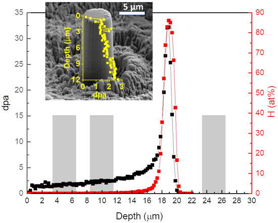
Figure 1.
SRIM calculated dpa vs. depth in 2 MeV proton irradiated AM 316L SS. The inset is an SEM image of a typical planar micropillar prepared. The gray boxes refer to the cross-sectional micropillars.
The present study is motivated to reduce dpa uncertainty in micropillar compression testing. The uncertainty reduction is essential due to the deformation mechanisms’ sensitivity to local dpa values. We applied compressive stress on pillars prepared on the cross-section of the irradiated samples. Depending on the distance from the irradiated surface, pillars at different damage levels can be prepared from one irradiated specimen. This process was performed to reduce data fluctuation and uncertainty. The gray boxes in Figure 1 are the locations of the cross-sectional micropillars prepared for the present study. Compared with the conventional planar pillar compression in which pillars are prepared from the original irradiated surface, the cross-sectional pillars have no damage gradient along the pillar height direction.
The second motivation of the present study is to apply the technique of in situ scanning electron microscopy (SEM) imaging and micropillar compression to clarify deformation mechanisms further. Our previous pillar compression experiments reached severe deformation with the maximum strain exceeding 20% [11]. Since twinning can occur under severe deformation, we could not exclude the possibility that twinning occurred at the later deformation stage instead of being the cause of yielding. Furthermore, since the morphology changes of compressed pillars due to twinning and dislocation gliding are differentiable under SEM, it is feasible to use in situ deformation morphology changes as supplementary information to study deformation mechanisms.
2. Experimental Procedure
The AM 316L SS was manufactured using the direct energy deposition method. A LENS MTS 500 printer (Optomec Inc., Albuquerque, United States) was used with a 400 W laser. The printing was performed in an Ar atmosphere. The laser spot size was 600 µm, and the scanning speed was 12.7 mm/s. The spacing between scanning paths was about 250 µm. Table 1 provides the alloy composition.

Table 1.
Chemical composition (wt.%) of AM-316L SS analyzed by inductively coupled plasma (ICP) and LECO combustion methods. Adapted from ref. [12].
The as-printed AM-316L block was annealed at 983 °C for 45 min to remove residual stress. Early studies on the same alloy showed that heat treatment is necessary to reduce the hardness of the AM 316L to a value close to the wrought variant [1]. The treated block was cut into pieces for mechanical polishing using SiC paper down to 1200 grit. Then, electropolishing was performed using 10% perchloric acid in methanol. The temperature of the electropolishing is −40 °C.
A 2 MeV proton ion irradiation was performed at 360 °C. Raster beam was used to guarantee uniformity. The proton fluence was 5.42 × 1019 cm2, corresponding to 1.74 dpa in the near-surface region (averaged from the surface to the depth of about 10 µm). Damage profiles were calculated using the SRIM-2013 program with the Kinchin-Pease mode [14,15]. The displacement energies of Fe, Ni, and Cr where assumed to be 40 eV, following the ASTM E521 standard [16].
Both planar micropillar compression and cross-sectional pillar compression tests were performed for mechanical property studies. First, Tescan FERA-3 plasma focused-ion-beam (FIB) (TESCAN, Brno, Czech Repubic) was used for electron backscatter diffraction (EBSD) analysis. The EBSD mapping was used to characterize grain morphologies and grain orientations. Through the assistance of EBSD, grains of specific orientations were selected for micropillar fabrication. The preparation of micropillars involved two steps. The first step used a 30 keV Xe beam from a Tescan FERA-3 Model GMH FIB to remove large volumes of materials. The second step used a 30 keV Ga beam from a Tescan LYRA-3 Model GMH FIB (TESCAN, Brno, Czech Repubic) for fine removal at a lower removal rate. Transmission electron microscopy (TEM) was performed using an FEI Tecnai G2 F20 TEM (FEI Company, Hillsboro, OR, USA). TEM lamellas were fabricated by using FIB. A Tescan Lyra-3 gallium FIB (TESCAN, Brno, Czech Repubic) and a 2 keV Ga beam was used in the last stage of the specimen thinning. The thicknesses of TEM specimens were measured by electron energy loss spectroscopy under TEM mode. The thickness measurements were repeated at least three times to obtain the average values. Void imaging was obtained using bright-field TEM. Local swelling was calculated using Swelling % = (V%) / (1 − V%), where V% is the volume fraction of voids. Dislocation loop imaging was obtained using dark-field TEM.
There were two types of pillars prepared and tested. One type was planar pillars prepared from the original irradiated surface. The other type of pillars were cross-sectional pillars, which were prepared from the cross-section of the irradiated sample. Figure 2a shows the ion irradiation direction, and Figure 2b compares these two pillar types. Note that the results about planar pillars have been previously reported in [11]. The results of cross-sectional pillars are obtained from the present study. For comparisons, we briefly summarize the previous planar pillar testing results and then discuss the current cross-sectional pillar testing results. In the end, results from the two types of pillars are compared.
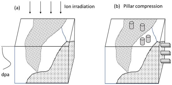
Figure 2.
Schematics of (a) ion irradiation and (b) post-irradiation micropillar preparation.
As shown in Figure 2b, planar pillars were prepared from the original surface exposed to proton ions. The pillar height corresponds to the normal direction of the irradiated surface. Various grains of different crystal orientations were selected. For a sample that did not experience proton irradiation, a total of 6 pillars were prepared from <001>, <011>, and <111> oriented grains. For a sample irradiated up to 1.74 dpa (average), a total of 8 pillars were prepared from <102>, <114>, <116>, and <216> oriented grains. For one selected grain, multiple micropillars were manufactured. The pillars were prepared intentionally at a distance away from grain boundaries. Therefore, all pillars were free of hardening contributed by dislocation interactions with grain boundaries. The boundary-free pillars were useful for reducing data fluctuations. For each pillar, the EBSD mapping provided the precise orientation information to calculate the Schmid factor. For each stress-strain curve, the yield strength was measured, and the critical resolved shear stress was calculated by using Schmid factors (m).
where λ represents the angle between load direction and slip plane, and ϕ is the angle between the load direction and slip direction.
The cross-sectional pillars were prepared from the cross-section of the irradiated sample. In order to apply EBSD mapping to image grain morphology and to determine Schmid factors, FIB was used to etch the cross-section for better smoothness. Such surface FIB treatment prior to EBSD was not necessary for mapping the irradiated surface (in planar pillar preparation) since electropolishing was sufficient. For the cross-sectional pillar testing, EBSD was used to (1) identify a large grain larger than the projected range of proton ions and (2) provide Schmid factor information.
In the previous study, pillars had a circular cross-section for the planar pillar testing on both unirradiated and irradiated samples. Each pillar was about 5 µm in diameter and about 10 to 12 µm in height. Pillar compression tests were conducted using a Hysitron TI-950 Triboindenter (Hysitron Corporation, Minneapolis, MI, USA) with a 20 µm flat-punch tip and high-load transducer. A constant strain rate of 0.001 s−1 was employed.
For the cross-sectional pillar testing in the present study, square pillars were prepared from one single grain <001> oriented. Square pillars were selected due to the convenience in (1) determining sliding plane direction after the compression test and (2) preparing multiple pillars from a small volume limited by ion penetration. Each pillar had a cross-section of about 3 µm × 3 µm and a height of about 6 µm. In situ pillar compression tests were performed using a Hysitron PI-85 Picoindenter (Hysitron Corporation, Minneapolis, MN, USA) inside a Tescan LYRA-3 Model GMH. The strain rate of compression was 0.001 s−1.
Figure 3 shows an SEM image of the fabricated pillars. The box indicates the region irradiated by the proton ions. The arrows refer to the beam bombardment direction. There was a total of four pillars, with one prepared at each depth of 5 µm, 10 µm, 15 µm, and 25 µm. The depths refer to the locations of the center of each pillar. Note that the deepest pillar was located at a depth outside the proton-damaged region. Hence, the deepest pillar was used as the 0 dpa reference pillar.
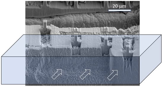
Figure 3.
SEM image of pillars that were prepared on the cross-section of the irradiated sample. All the pillars were prepared from the same grain. The arrows refer to the proton beam direction.
In Figure 1, the gray boxes represent pillar positions. The shallowest pillar at a depth of 5 µm corresponds to a local dpa of 1.71. The second pillar at a depth of 10 µm corresponds to a local dpa of 2.33. The third pillar at a depth of 15 µm was not included since pillar compression failed due to an alignment issue. The fourth pillar was located at 25 µm, outside the proton irradiated region. Although the peak H concentration was high (85 at.%), H atoms were distributed within a narrow region. The full width at half maximum was 1.1 µm. For all three pillars, the amount of H was negligible.
3. Irradiation Induced Defects
A previous study has reported the irradiation-induced defects of the same sample after proton irradiation [12]. Some data was reproduced here for ease of discussion. Figure 4a shows one typical bright-field TEM image at a depth of about 5 µm beneath the surface. The statistic of void size distribution is summarized beneath the TEM image. Void sizes range from 4 nm to 27 nm in diameter. The average void diameter is about 14 nm. These voids are easily differentiable from processing introduced pores, which are typically 100 nm in diameter. The void density was measured to be 9.5 × 10²⁰/m3.
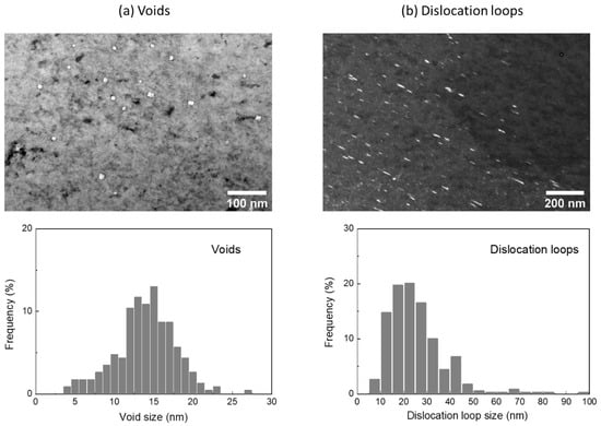
Figure 4.
(a) Bright-field TEM image of voids and statistics of void size distributions, and (b) dark-field TEM image of dislocations and their size distributions. The depth is about 5 µm beneath the surface (adapted from ref. [12]).
Figure 4b shows a dark-field TEM image under a condition to maximize the contrast of dislocation loops. Frank loops are on {111} habit planes in face-centered cubic (FCC) metals and have a Burgers vector of 1/3<111>. The dark-field TEM image was obtained by rel-rod method. Dislocation loops can be revealed by tilting the g vector close to <311> two-beam conditions along the [011] zone axis. Since the imaging illuminates loops only on one of the four close-packed planes, the actual dislocation density should be four times higher than that obtained from TEM measurement. Dislocation loop size was measured by the line tool in ImageJ. The top right portion of the TEM image in Figure 4b is devoid of loops, most likely due to the misorientation with the grain. The misoriented region was excluded from the loop density calculation. The statistical analysis is shown in the bottom of Figure 4b. The average dislocation loop diameter was about 25 nm. The total dislocation loop density was 1.33 × 10²¹/m3. There were no twins or precipitations observed.
4. Planar Pillar Testing
Figure 5a,b show the resolved shear stress (RSS) vs. strain curves obtained from the unirradiated and irradiated samples. The data was reproduced from [12]. The raw stress vs. strain data was scattered due to the difference in axial pillar orientations. Using the Schmid factor from EBSD, the data scattering was significantly reduced after converting stress to RSS. It was apparent that irradiated sample became harder. For the unirradiated sample, the average critical resolved shear stress was 87 ± 13 MPa. For the proton irradiated sample, the average was 246 ± 25 MPa, an increase of 182.8%. The uncertainty comes from the statistical analysis of values obtained from multiple pillars. A few pillars show the activation of numerous slip systems. These pillars were not included in the data analysis since interception of different slip systems can increase hardness.
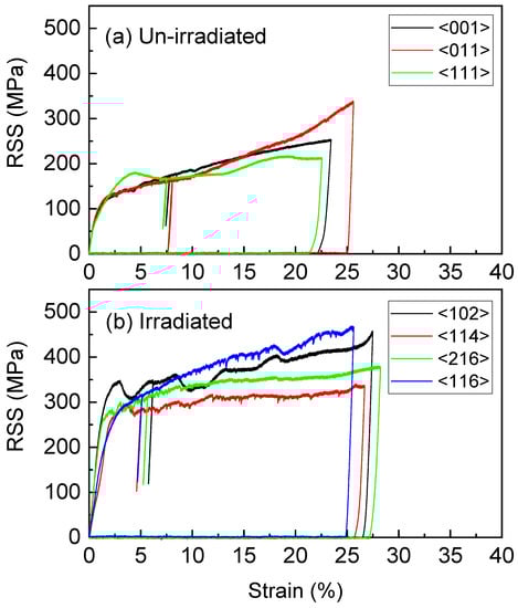
Figure 5.
Resolved shear stress (RSS) vs. strain curves were obtained from the selected planar pillars of (a) unirradiated and (b) irradiated AM 316L (adapted from ref. [12]).
The observed hardness changes can be well explained by the Orowan dispersed barrier model [17,18,19]. The yield stress change is thought to be caused by dislocation blocking due to interactions with voids and dislocation loops which act as obstacles on dislocation migration planes. For a specific obstacle type j, the resulting yield stress change was calculated by:
where is the shear modulus of the material, which is 80 GPa for 316L SS. is the Burgers vector of the interacting dislocation, which is 0.258 nm. is the number density of obstacles. is the size of the obstacle. is a constant describing the strength of a specific barrier type. For loops, = 0.5 was previously suggested [20]. For voids, was also suggested to be 0.5 if void shearing is more likely than Orowan pinning [20]. The parameter is the Taylor factor for the description of polycrystalline material. For a single-crystal pillar with the Schmid factor known, critical resolved shear stress for yielding on the {111} gliding plane can be calculated by:
Using the density and size of voids and dislocations measured from TEM, Equation (3) predicts (the critical resolved shear stress enhancement from dislocations) to be 119 MPa, and (the enhancement from voids) to be 38 MPa. Dislocation loops were the dominant contributors to hardening. The combined enhancement of critical resolved shear stress was estimated to be 157 MPa, which is in good agreement with the experimental value of 159 MPa.
5. Cross-Sectional Pillar Testing
Figure 6a–c plot the engineering stress vs. strain curves for 0 dpa, 1.71 dpa, and 2.33 dpa pillars. SEM images at the right show the pillars’ behavior after compression. Judging by the stress–strain curves, the hardness of pillars increased with increasing damage levels. The hardness data were obtained based on the 0.2% offset method. The slope of the elastic deformation region was obtained through a linear fitting. Table 2 summarizes the mechanical properties extracted from cross-sectional pillar compression testing. All pillars were <001> oriented. Based on EBSD data, a Schmid factor of m = 0.408 was determined. The predicted {111} gliding plane agrees with the slip direction observed from the SEM imaging.
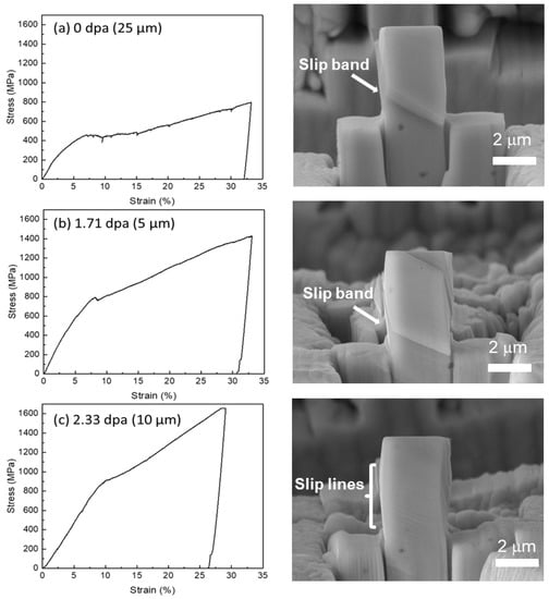
Figure 6.
Engineering stress vs. strain curves and SEM images after compression tests for (a) 0 dpa pillar, (b) 1.71 dpa pillar, and (c) 2.33 dpa pillar.
Table 2.
Results from cross-sectional pillar compression.
As shown in SEM images, the 0 dpa pillar possessed only a single slip band. The 1.71 dpa pillar developed two parallel slip bands. Between these two slips, there was a region that developed parallel slip lines. The 2.33 dpa pillar did not develop any slip bands like the other two pillars. Instead, only slip lines were observed. Only one slip direction (if a slip occurs) was observed for all three pillars. There was no secondary slip direction activated. This avoids the hardening due to the intercepting of multiple slip directions.
6. Post-Compression TEM Characterization
FIB was applied on each compressed pillar to prepare a TEM specimen to further understand the deformation mechanism. Figure 7 shows a TEM micrograph of the 0 dpa pillar. As expected, no grain boundaries were observed. Deformation-induced dislocations were visible. No twinning was observed from the localized diffraction patterns.
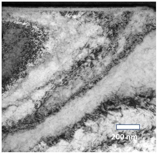
Figure 7.
TEM image from the compressed 0 dpa pillar.
Figure 8 shows a TEM micrograph of the pillar irradiated to 1.71 dpa. The red arrow points to one irradiation-induced void, which was about 10 nm in diameter. Such a void was not introduced during the manufacturing process. The manufacturing-introduced cavities are typically a few hundred nanometers in diameter. Such manufacturing cavities are known to be filled with amorphous material enriched in oxygen and often exhibit a shell structure at the cavity-matrix interface. Dislocation bands were observed (as pointed by black arrows), suggesting gliding-mediated deformation mechanism.
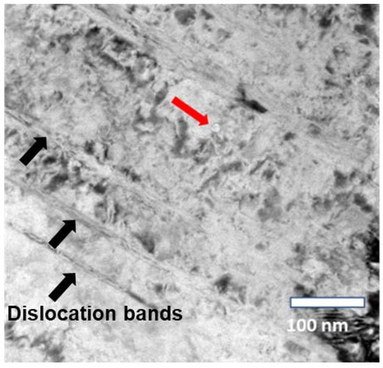
Figure 8.
TEM image obtained from the compressed 1.71 dpa pillar.
Significant void swelling was observed in the pillar at a depth of 10 µm, which received a higher damage level of 2.33 dpa. As shown in Figure 9a, voids of 20 to 50 nm diameters were observed. In addition, high-density dislocation bands were also observed. The bands in the image were parallel to each other with a separation distance of about 100 nm. The Fourier filtered high resolution TEM image (Figure 9b) clearly shows the existence of dislocations. The red lines indicate the atomic rows. There is no observation of twinning from both HRTEM and localized diffraction analysis.
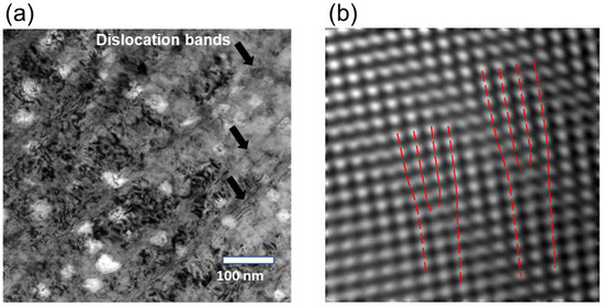
Figure 9.
(a) TEM image and (b) Fourier filtered high resolution TEM image, both obtained from the compressed 2.33 dpa pillar. The red lines indicate the atom rows.
7. Discussions
SEM images of the deformed pillars, as shown in Figure 6, suggest that the 2.33 dpa cross-sectional pillar exhibited more homogeneous plasticity flow than the other two pillars. Various groups have previously studied the effects of radiation damage on plasticity flow. For example, more homogeneous plasticity was reported in Fe-irradiated 304L SS [21], and Fe-irradiated Fe [22]. However, the observation was the opposite for proton-irradiated 304 SS [23]. Early studies discussed the inconsistency is due to the energy cost difference between creating a new slip event and continuing a dislocation along an existing plane [23].
The present study used 3 μm × 3 μm micropillars for cross-sectional pillar testing. The previous work on planar pillar testing used a slightly larger pillar of about 5 µm [11]. The size effect may explain the slight difference between the 0 dpa cross-sectional pillar and 0 dpa planar pillars. The size effect follows an inverse power law in FCC and body-centered cubic (BCC) metals [24,25,26,27]. The yield strength decreases with increasing pillar size until a critical size is reached. Beyond that size, the yield strength matches the bulk value. The sensitivity of the size effect is related to the critical temperature [28]. For metals with a low critical temperature, yield strength difference is mainly attributed to size-dependent strengthening factors. For metals having a high critical temperature, the contribution from the Peierls barrier becomes significant, which is not size sensitive. The size effect will be further studied.
Back to the motivation of the present study to reduce dpa uncertainty in determining dependence on dpa, Figure 10 compares the as a function of local dpa determined from planar pillar testing and cross-sectional pillar testing. Overall, results from both types of pillars agree with each other. The green symbol refers to the planar pillars. The black errors are the corresponding errors/uncertainly. The error bar of dpa (black, horizontal) comes from the dpa gradient along 12 µm tall pillars. The error bar of (black, vertical) comes from the statistics of various pillars of different orientations. The red color refers to cross-sectional pillars. Due to the small cross-section of pillars, the associated dpa gradient over the cross-section is much smaller, leading to less uncertainty on the dpa error bar along the horizontal direction. Note that the missing error bar for critical resolved shear stress of cross-sectional pillars is due to the lack of replicate data points. The data of planar pillars of 1.74 dpa (average) is very close to that of the cross-sectional pillar of 1.71 dpa (average). Due to the flexibility and better accuracy in selecting regions of specific local value, the cross-sectional pillar of 2.33 dpa can show a data point at a higher local dpa value.
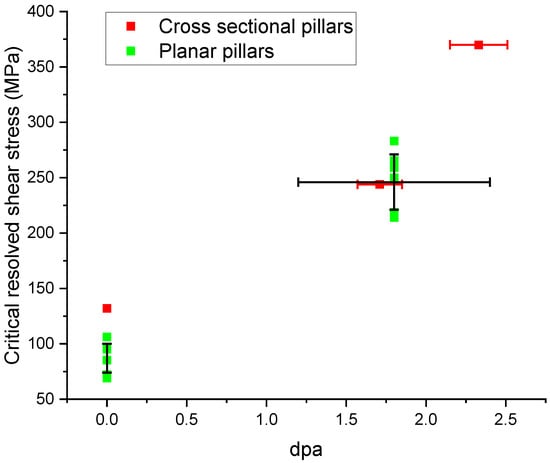
Figure 10.
Comparison of critical resolved shear stress as a function of local dpa, obtained from planar and cross-sectional pillar compression.
Although twinning was observed previously in the planar micropillar compression [11,12], there is no observation of twins in the present study. The cause is unclear, and it may be due to the size effects since the present study uses small pillars. The size effect needs to be systematically studied for both planar pillar compression and cross-sectional pillar compression. Dislocation nucleation and twin nucleation may have different size sensitivity.
8. Conclusions
Radiation responses and mechanical property changes of additively manufactured (AM) 316L stainless steels were studied. The planar pillars which were fabricated from the irradiated surface were previously studied. The present study extends and compares the results with pillars fabricated from the irradiated cross-sectional surface. The critical interest was to reduce dpa uncertainty in a pillar. The conventional planar pillars of a typical height of 10 µm have local dpa values differing by a factor of ~2, which bring in considerable dpa uncertainty and the different deformation mechanisms along the pillar. The study shows that cross-sectional pillars are able to show hardness-dpa dependence with better dpa accuracy.
Author Contributions
Conceptualization, C.S. and L.S.; methodology, C.-H.S., C.S. and L.S.; investigation, C.-H.S., M.P., Y.L., S.X. and M.D.M.; data curation, C.-H.S., M.P., Y.L. and S.X.; writing—original draft preparation, C.-H.S., C.S. and L.S.; writing—review and editing, C.-H.S., C.S. and L.S. All authors have read and agreed to the published version of the manuscript.
Funding
This work was supported by National Nuclear Security Administration (NNSA) grant DE-NA0003921 and Idaho National Laboratory Laboratory-Directed Research & Development Program under Department of Energy (DOE) Idaho Operations Office Contract DE-AC07-051D14517. Ion irradiation was supported by Nuclear Science User Facilities through RTE project.
Institutional Review Board Statement
Not applicable.
Informed Consent Statement
Not applicable.
Data Availability Statement
The data presented in this study are available on request from the corresponding author.
Acknowledgments
M.P. and L.S. acknowledge the support from NNSA grant DE-NA0003921. C. Sun and M.D.M. acknowledge the support by the Idaho National Laboratory Laboratory-Directed Research & Development Program under Department of Energy (DOE) Idaho Operations Office Contract DE-AC07-051D14517. Ion irradiation was supported by Nuclear Science User Facilities through RTE project.
Conflicts of Interest
The authors declare no conflict of interest.
References
- Cheng, S.; Yun, W.; Michael, D.M.; Nathan, D.J.; Frank, L.; Ju, L. Additive manufacturing for energy: A review. Appl. Energy 2021, 282, 116041. [Google Scholar]
- Zhong, Y.; Rännar, L.-E.; Liu, L.; Koptyug, A.; Wikman, S.; Olsen, J.; Cui, D.; Shen, Z. Additive manufacturing of 316L stainless steel by electron beam melting for nuclear fusion applications. J. Nucl. Mater. 2017, 486, 234–245. [Google Scholar] [CrossRef]
- Kan, W.H.; Chiu, L.N.S.; Lim, C.V.S.; Zhu, Y.; Tian, Y.; Jiang, D.; Huang, A. A critical review on the effects of process-induced porosity on the mechanical properties of alloys fabricated by laser powder bed fusion. J. Mater. Sci. 2022, 57, 9818–9865. [Google Scholar] [CrossRef]
- Shang, Z.; Fan, C.; Ding, J.; Xue, S.; Gabriel, A.; Shao, L.; Voisin, T.; Wang, Y.M.; Niu, T.; Li, J.; et al. Heavy ion irradiation response of an additively manufactured 316LN stainless steel. J. Nucl. Mater. 2020, 546, 152745. [Google Scholar] [CrossRef]
- Saeidi, K.; Gao, X.; Zhong, Y.; Shen, Z. Hardened austenite steel with columnar sub-grain structure formed by laser melting. Mater. Sci. Eng. A 2015, 625, 221–229. [Google Scholar] [CrossRef]
- Abdi, F.; Eftekharian, A.; Huang, D.; Rebak, R.B.; Rahmane, M.; Sundararaghavan, V.; Kanyuck, A.; Gupta, S.K.; Arul, S.; Jain, V.; et al. Grain boundary engineering of new additive manufactured polycrystalline alloys. Forces Mech. 2021, 4, 100033. [Google Scholar] [CrossRef]
- Yin, H.; Song, M.; Deng, P.; Li, L.; Prorok, B.C.; Lou, X. Thermal stability and microstructural evolution of additively manufactured 316L stainless steel by laser powder bed fusion at 500–800 °C. Addit. Manuf. 2021, 4, 101981. [Google Scholar] [CrossRef]
- Zhang, X.; McMurtrey, M.D.; Wang, L.; O’Brien, R.C.; Shiau, C.-H.; Wang, Y.; Scott, R.; Ren, Y.; Sun, C. Evolution of Microstructure, Residual Stress, and Tensile Properties of Additively Manufactured Stainless Steel Under Heat Treatments. JOM 2020, 72, 4167–4177. [Google Scholar] [CrossRef]
- Ziętala, M.; Durejko, T.; Polański, M.; Kunce, I.; Płociński, T.; Zieliński, W.; Łazińska, M.; Stępniowski, W.; Czujko, T.; Kurzydłowski, K.J.; et al. The microstructure, mechanical properties and corrosion resistance of 316L stainless steel fabricated using laser engineered net shaping. Mater. Sci. Eng. A 2016, 677, 1–10. [Google Scholar] [CrossRef]
- Chen, W.; Voisin, T.; Zhang, Y.; Forien, J.-B.; Spadaccini, C.M.; McDowell, D.L.; Zhu, T.; Wang, Y.M. Microscale residual stresses in additively manufactured stainless steel. Nat. Comm. 2019, 10, 4338. [Google Scholar] [CrossRef]
- Shiau, C.-H.; Sun, C.; McMurtrey, M.; O′Brien, R.; Garner, F.A.; Shao, L. Orientation-selected micro-pillar compression of additively manufactured 316L stainless steels: Comparison of as-manufactured, annealed, and proton-irradiated variants. J. Nucl. Mater. 2022, 566, 153739. [Google Scholar] [CrossRef]
- Shiau, C.-H.; McMurtrey, M.D.; O’Brien, R.C.; Jerred, N.D.; Scott, R.D.; Lu, J.; Zhang, X.; Wang, Y.; Shao, L.; Sun, C. Deformation behavior and irradiation tolerance of 316 L stainless steel fabricated by direct energy deposition. Mater. Des. 2021, 204, 109644. [Google Scholar] [CrossRef]
- McMurtrey, M.; Sun, C.; Rupp, R.; Shiau, C.-H.; Hanbury, R.; Jerred, N.; O’Brien, R. Investigation of the irradiation effects in additively manufactured 316L steel resulting in decreased irradiation assisted stress corrosion cracking susceptibility. J. Nucl. Mater. 2020, 545, 152739. [Google Scholar] [CrossRef]
- Ziegler, J.F.; Ziegler, M.D.; Biersack, J.P. SRIM–The stopping and range of ions in matter. Nucl. Instrum. Methods Phys. Res. Sect. B Beam Interact. Mater. At. 2010, 268, 1818–1823. [Google Scholar] [CrossRef]
- Stoller, R.E.; Toloczko, M.B.; Was, G.S.; Certain, A.G.; Dwaraknath, S.; Garner, F.A. On the use of SRIM for computing radiation damage exposure. Nucl. Instrum. Methods Phys. Res. Sect. B Beam Interact. Mater. At. 2013, 310, 75–80. [Google Scholar] [CrossRef]
- ASTM Standard E521-16; Standard Practice for Investigating the Effects of Neutron Radiation Damage Using Charged-Particle Irradiation. ASTM International: West Conshohocken, PA, USA, 2016.
- Heintze, C.; Bergner, F.; Hernández-Mayoral, M. Ion-irradiation-induced damage in Fe–Cr alloys characterized by nanoindentation. J. Nucl. Mater. 2011, 417, 980–983. [Google Scholar] [CrossRef]
- Bergner, F.; Pareige, C.; Hernández-Mayoral, M.; Malerba, L.; Heintze, C. Application of a three-feature dispersed-barrier hardening model to neutron-irradiated Fe–Cr model alloys. J. Nucl. Mater. 2014, 448, 96–102. [Google Scholar] [CrossRef]
- Chen, W.-Y.; Miao, Y.; Gan, J.; Okuniewski, M.A.; Maloy, S.A.; Stubbins, J.F. Neutron irradiation effects in Fe and Fe-Cr at 300 °C. Acta Mater. 2016, 111, 407–416. [Google Scholar] [CrossRef]
- Hashimoto, N.; Wakai, E.; Robertson, J. Relationship between hardening and damage structure in austenitic stainless steel 316LN irradiated at low temperature in the HFIR. J. Nucl. Mater. 1999, 273, 95–101. [Google Scholar] [CrossRef]
- Paccou, E.; Tanguy, B.; Legros, M. Micropillar compression study of Fe-irradiated 304L steel. Scr. Mater. 2019, 172, 56–60. [Google Scholar] [CrossRef]
- Grieveson, E.M.; Armstrong, D.E.J.; Xu, S.; Roberts, S.G. Compression of self-ion implanted iron micropillars. J. Nucl. Mat. 2012, 430, 119–124. [Google Scholar] [CrossRef]
- Reichardt, A.; Lupinacci, A.; Frazer, D.; Bailey, N.; Vo, H.; Howard, C.; Jiao, Z.; Minor, A.M.; Chou, P.; Hosemann, P. Nanoindentation and in situ microcompression in different dose regimes of proton beam irradiated 304 SS. J. Nucl. Mat. 2017, 486, 323–331. [Google Scholar] [CrossRef]
- Uchic, M.D.; Shade, P.A.; Dimiduk, D.M. Plasticity of micrometer-scale single crystals in compression. Annu. Rev. Mater. Res. 2009, 39, 361–386. [Google Scholar] [CrossRef]
- Greer, J.R.; de Hosson, J.T.M. Plasticity in small-sized metallic systems: Intrinsic versus extrinsic size effect. Prog. Mater. Sci. 2011, 56, 654–724. [Google Scholar] [CrossRef]
- Parthasarathy, T.A.; Rao, S.I.; Dimiduk, D.M.; Uchic, M.D.; Trinkle, D.R. Contribution to size effect of yield strength from the stochastics of dislocation source lengths in finite samples. Scr. Mater. 2007, 56, 313–316. [Google Scholar] [CrossRef]
- Dimiduk, D.M.; Uchic, M.D.; Parthasarathy, T.A. Size-affected single-slip behavior of pure nickel microcrystals. Acta Mater. 2005, 53, 4065–4077. [Google Scholar] [CrossRef]
- Guo, E.-Y.; Xie, H.-X.; Singh, S.S.; Kirubanandham, A.; Jing, T.; Chawla, N. Mechanical characterization of microconstituents in a case duplex stainless steel by micropillar compression. Mat. Sci. Eng. A 2014, 598, 98–105. [Google Scholar] [CrossRef]
Publisher’s Note: MDPI stays neutral with regard to jurisdictional claims in published maps and institutional affiliations. |
© 2022 by the authors. Licensee MDPI, Basel, Switzerland. This article is an open access article distributed under the terms and conditions of the Creative Commons Attribution (CC BY) license (https://creativecommons.org/licenses/by/4.0/).