1. Introduction
30CrMnSiA, a high-strength medium carbon steel, has been widely utilized in many industries, such as aero engines and automobiles. Due to its excellent mechanical properties, such as high strength, superior toughness, and hardenability, 30CrMnSiA steel is commonly used in the production of aircraft engine piston materials, crank bearing bushings, aircraft motor frames, and gearbox friction plates [
1,
2,
3,
4,
5,
6], and has even more excellent prospects for applications. However, the working environment of 30CrMnSiA workpieces is complex and variable. Moreover, for a given application, the 30CrMnSiA material in its original state cannot meet the requirements [
7,
8,
9,
10], such as high hardness and excellent wear resistance. Appropriate surface treatments must be applied to ensure the quality of 30CrMnSiA workpieces.
Over several decades, plenty of research has been carried out to improve the surface mechanical properties, such as wear resistance and impact resistance, of 30CrMnSiA. Zhou et al. [
11] studied the macro- and micro-damage behaviors of 30CrMnSiA steel under the impact of GCr15 steel projectiles. The results showed that, with the decrease in specimen thickness and the increase in projectile velocity, the shape of the specimen surface crater changed to a conical shape, and the specimen on the back side showed an evident lamellar cracking phenomenon. Fu et al. [
12] studied the effects of continuous electron beam treatment on the surface hardening and microstructure changes of 30CrMnSiA investigated experimentally via a multi-purpose electron beam machine pro-beam system. The study found that the microstructure of the electron beam-hardened area is composed of acicular lower bainite, feathered upper bainite, and part lath martensite, and the surface hardness increased 1–3 times with a tiny change of surface roughness. Tang et al. [
13] performed a plasma nitrogen carbonitriding treatment of 30CrMnSiA steel with an addition of rare earth. They studied the effects of rare earth on the surface morphology, phase structure, and mechanical properties of the carbonitriding layer. The research found that the nitrocarburized surface hardness showed a decreasing trend, with the rare earth addition increasing in the carrier gas, and the wear resistance of the experimental steel could be improved remarkably by plasma RE nitrocarburizing. Yan et al. [
14] used laser quenching technology (LQ) to post-treat ionomer nitriding (PN)-treated 30CrMnSiA steel to improve the surface properties of the specimens and compared the surface microstructure and mechanical properties with those of PN and LQ alone. The results showed that, due to the formation of retained austenite and Fe3O4 in the modified layer of 30CrMnSiA steel after the PN + LQ treatment, the thickness of the modified layer and its hardness and wear resistance were significantly improved compared to the treatment of specimens with PN or LQ alone.
Although the surface hardness of the material treated by the nitriding and laser quenching technique is substantially increased, the modified layer is thin and brittle. Therefore, it cannot withstand excessive contact stresses and impact loads. Since 2008, Liu [
15,
16,
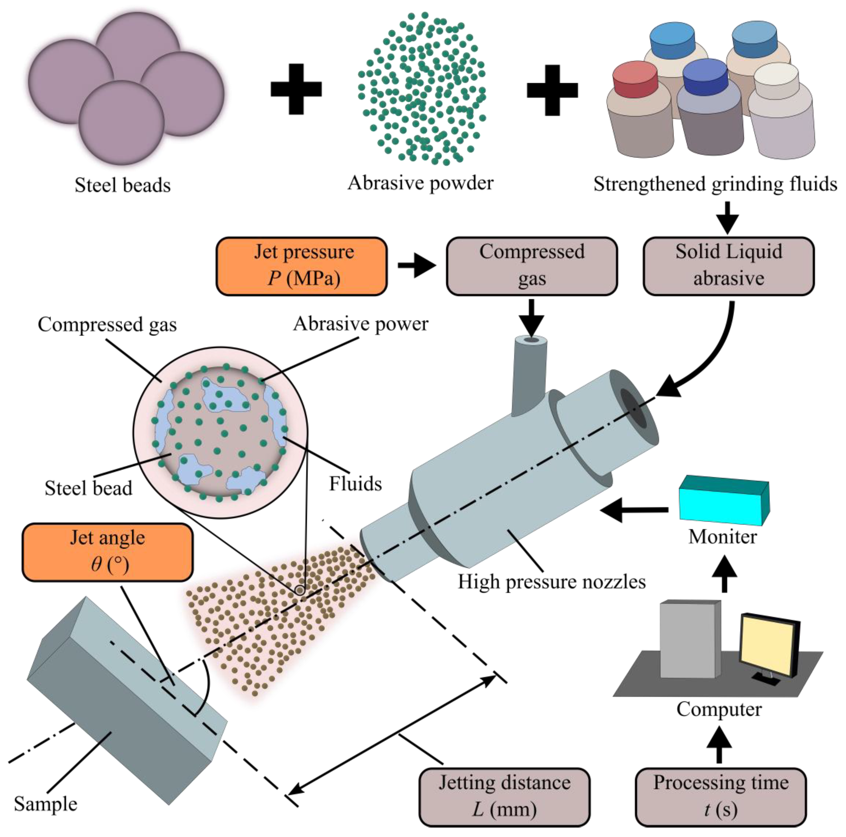
17] has proposed and engaged in research on the strength-modified grinding technique (SMGT). The SMGT is a new surface treatment technique that integrates surface plasticity strengthening and grinding micro-cutting into one, and the principle is that, under the impetus of compressed gas, the steel beads covered with the strengthened grinding fluids carry the abrasive powder to impact the surface of the workpiece to produce micro-cutting to remove the deterioration layer and significantly improve the surface properties of the workpiece. The introduction of SMGT in metallic materials with improved surface properties has been reported in the past decade [
18,
19,
20,
21]. The technique can enhance the surface mechanical properties of materials such as roughness, fatigue, corrosion, wear resistance, and impact resistance by forming a thick and strength-modified layer on the surface [
22,
23,
24]. Therefore, the SMGT is an effective method of surface strengthening and modification and can show perfect universality for many kinds of metallic materials.
In this study, 30CrMnSiA bearing steel was post-treated by the SMGT. The effect of jet pressure and jet angle of the SMGT on the surface micromorphology, microstructure, and microhardness of 30CrMnSiA steel specimens was systematically examined and analyzed. The formation mechanism of the surface microstructure and micromorphology was discussed. The research aims to enhance the surface properties of 30CrMnSiA bearing steel and to provide experimental support for its application in the field of aerospace.
4. Discussion
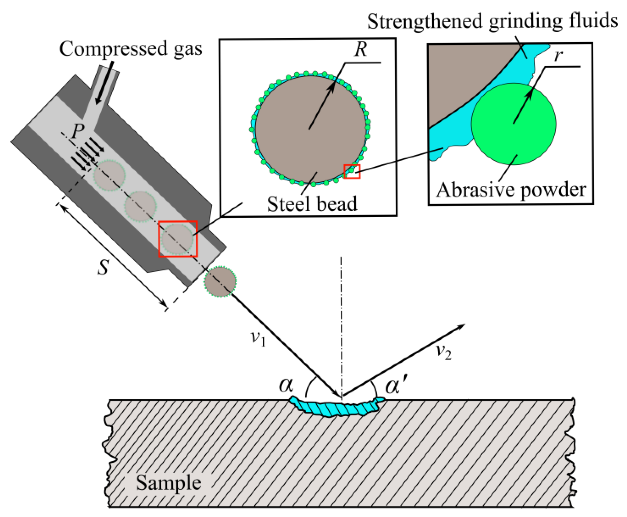
In this study, the energy conversion during the SMGT treatment can be divided into two stages. Incidence stage: The initial impact kinetic energy of the three-phase mixed abrasive is converted into deformation energy of the processed surface microstructures. Rebound stage: The elastic deformation of the processed surface microstructures returns part of the kinetic energy to the abrasive. Most of the kinetic energy is transformed into the plastic deformation energy of the processed surface due to plasticity contact. As shown in
Figure 12, a steel bead with
n abrasive powder attached to its surface is propelled by compressed air with pressure
P, jets out from a nozzle pipe of length
S, shoots onto the process surface with velocity
v1 and angle α, then bounces back with a velocity
v2 and angle α′.
The initial total kinetic energy
ETotal and initial velocity
v1 before the impact can be obtained, respectively, by:
where
M and
m are the masses of the steel beads and the abrasive powder, respectively;
R and
r are the radius of the steel beads and abrasive powder, respectively. Regarding steel beads and abrasive powders as rigid, the energy conversion rate and plastic deformation energy in the surface layer can be obtained, respectively [
35], by:
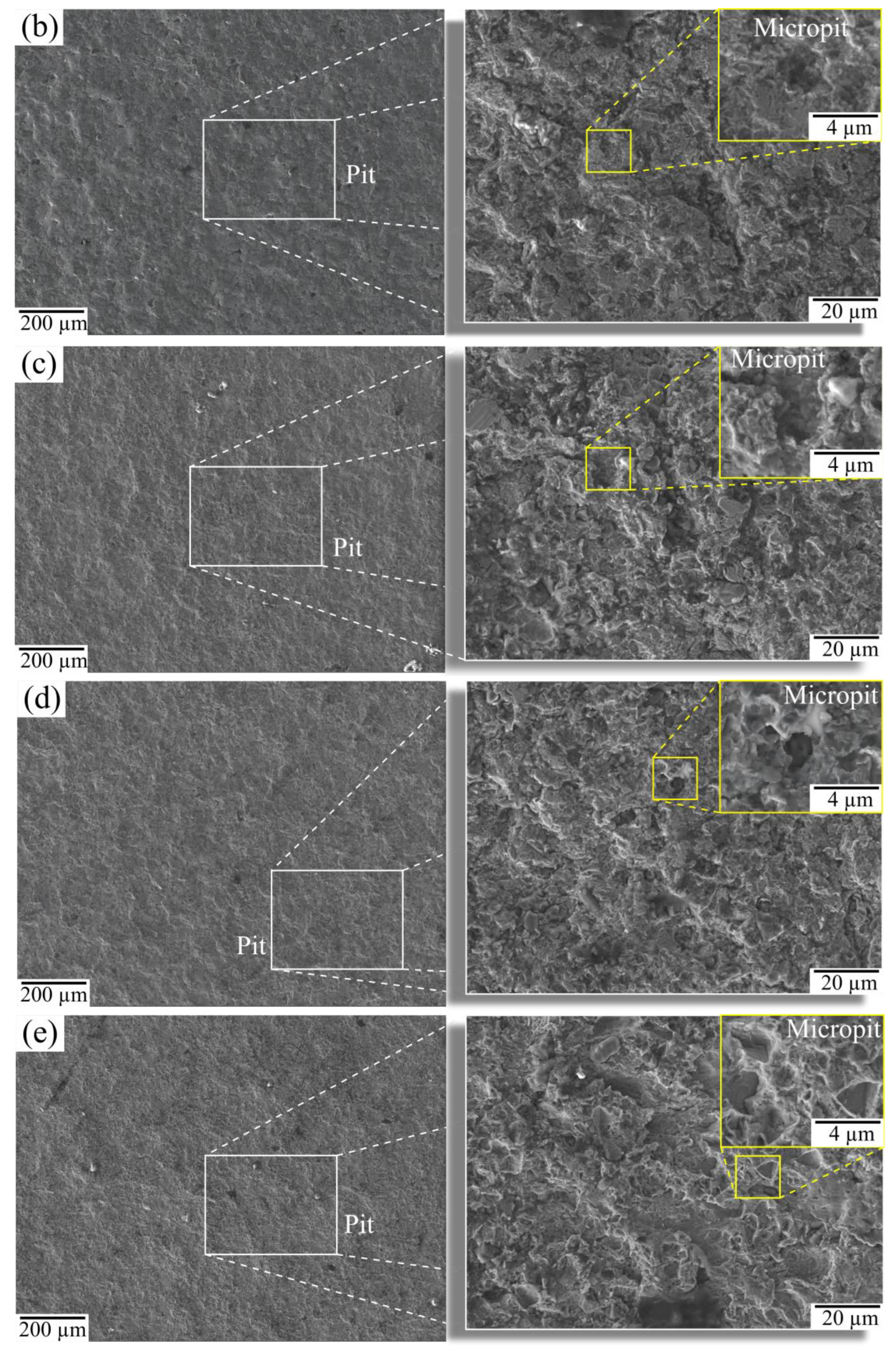
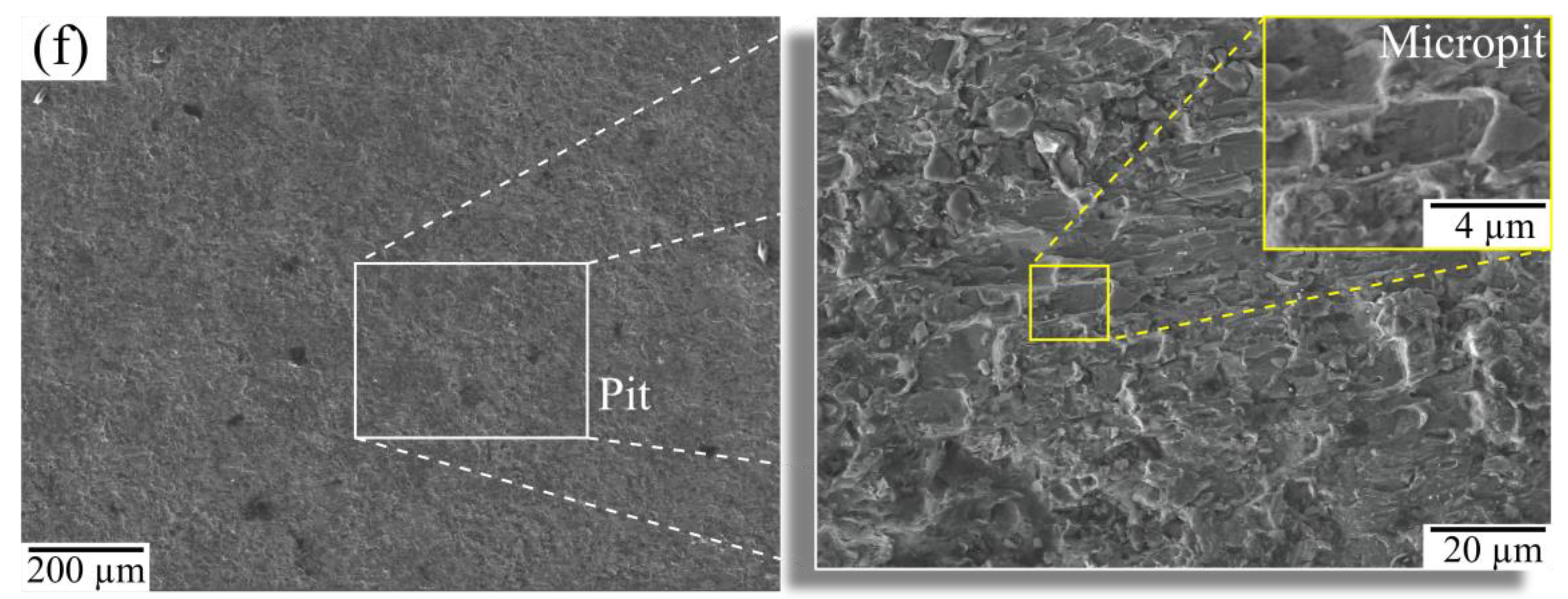
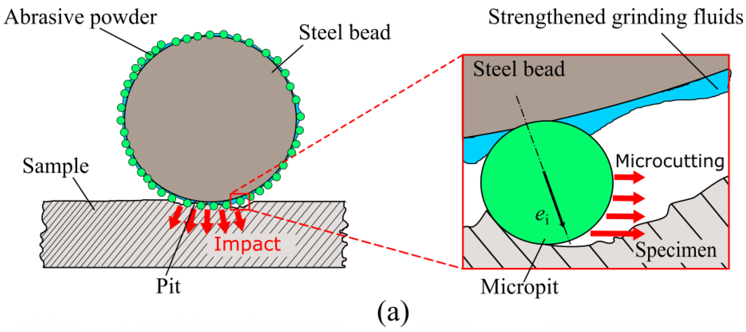
In this experiment, the surface with SMGT treatment showed a morphology with plenty of micropits inside the pit and overlaps between pits. According to
Figure 13a, it can be seen that, in the process of the three-phase mixed abrasive impact on the surface layer, the steel beads mainly provide the impact kinetic energy for the processed surface to obtain plastic deformation energy. Then plastic deformation occurs, and pits are produced. Moreover, steel beads also transfer part of the kinetic energy to the abrasive powder attached to its surface. The abrasive powder mainly provides micro-cutting. The abrasive powder with specific kinetic energy is equivalent to the micro-cutting edge, which micro-cuts the inner surface of the pit, thus causing the formation of micropits inside the pit. According to
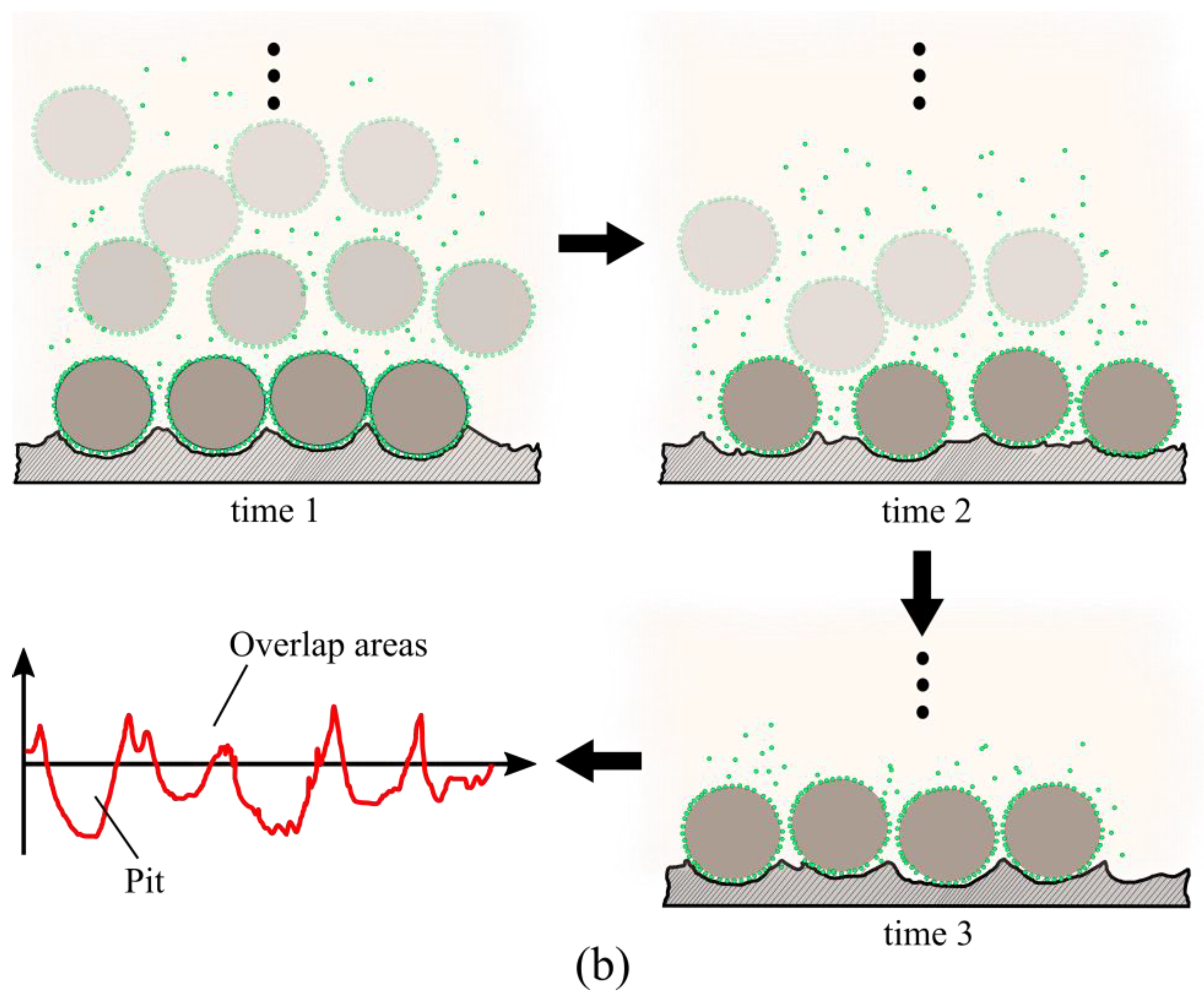
Figure 13b, it can be seen that, as steel beads with strengthened grinding fluids and abrasive powder attached to the surface strike the processed surface to create a pit, the material at the edge of the pit migrates and is extruded, forming a bulge. As the abrasive continuously impacts the process surface, the morphology produced by the previous impact is constantly reshaped, creating the microstructure in that the pit contains micropits and overlaps between the pits.
Related research shows that the energy conversion rate increases with jet velocity. In contrast, when the initial kinetic energy is constant, it mainly depends on the mechanical properties of materials [
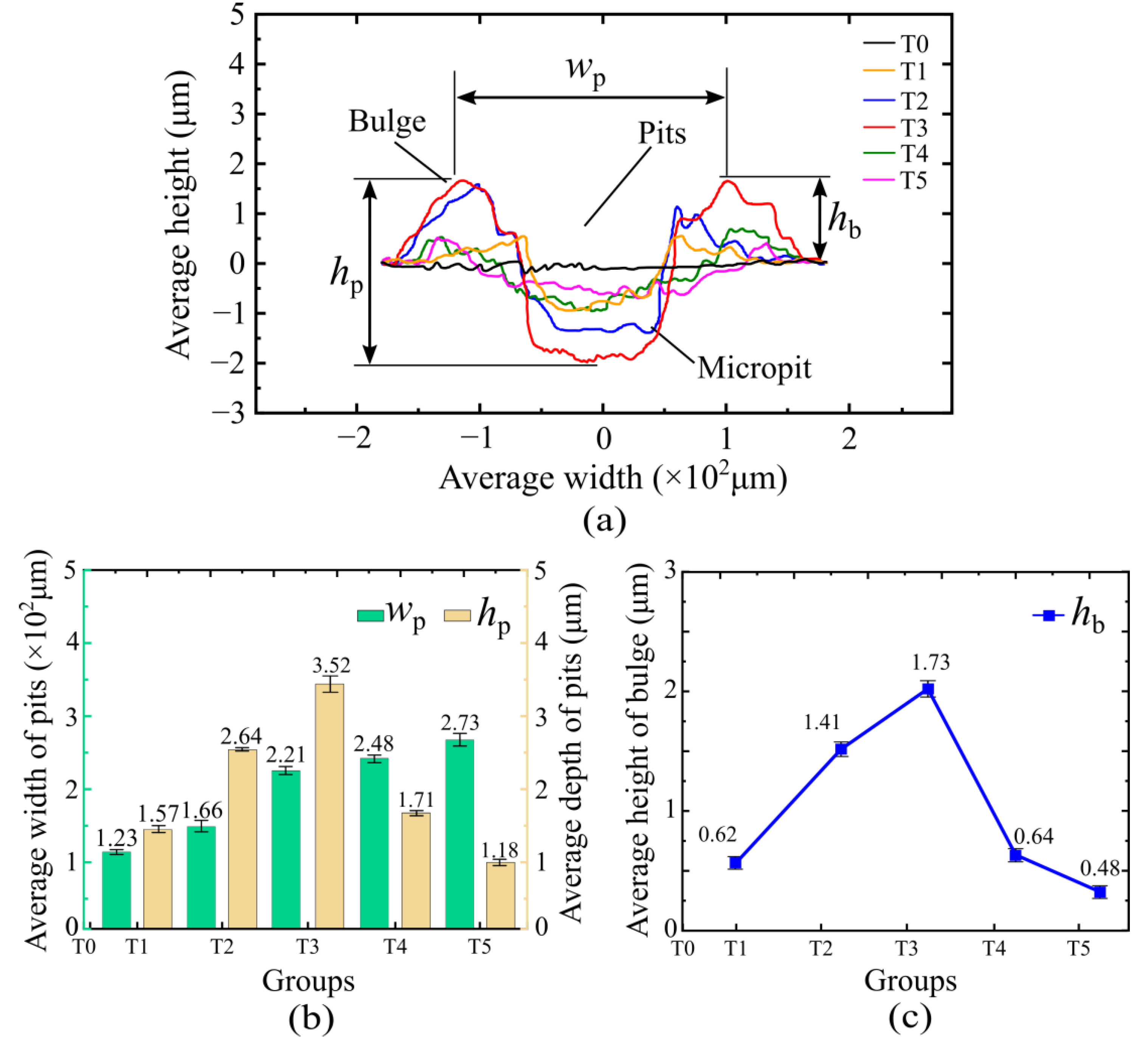
35]. It is found that the pit width, depth, and bulge height are positively correlated with the jet pressure in this paper. Combining Formulas (4) and (5) and
Figure 14a, it is shown that the energy conversion rate is positively correlated with the jet pressure, i.e.,
K ∝
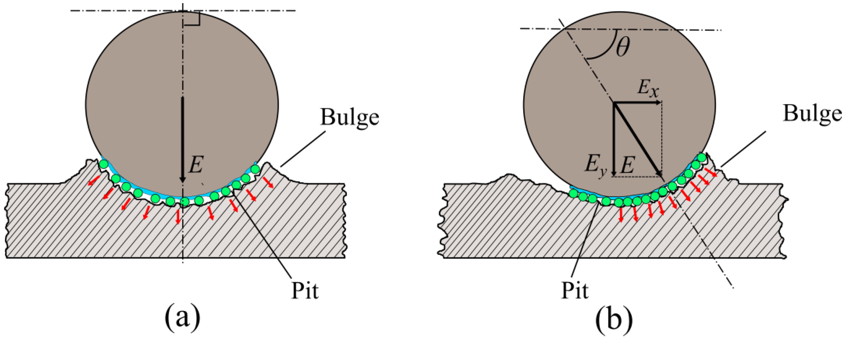
P. At a constant jet angle of 90°, the plastic deformation energy in the processed surface is positively correlated with the jet pressure when combined with Formula (6). The increased plastic deformation energy is reflected in the pit width increase from 123 µm to 221 µm, the pit depth increase from 1.57 µm to 3.52 µm, and the increase in bulge height from 0.62 µm to 1.73 µm. In this paper, the pit width, depth, and bulge height positively correlate with the jet angle. Since the initial total kinetic energy remains invariant at a constant jet pressure, the energy conversion rate remains invariant.
Figure 14b shows that the plastic deformation energy can be decomposed into component
Ex in the direction of the processed surface and component
Ey in the vertical:
Under the influence of Ey, steel beads deliver an impact force that creates pits on the processed surface. Meanwhile, in the presence of Ex, steel beads are scratched in the direction of the machined surface, with the effect of broadening the already made pits further. As a result, as the jet angle increases, the kinetic energy along the processed surface decreases, and the broadening effect of the pit diminishes, further resulting in the pit width being reduced. While the kinetic energy in the vertical direction increases, the corresponding plastic deformation energy absorbed by the surface layer in the vertical direction also rises.
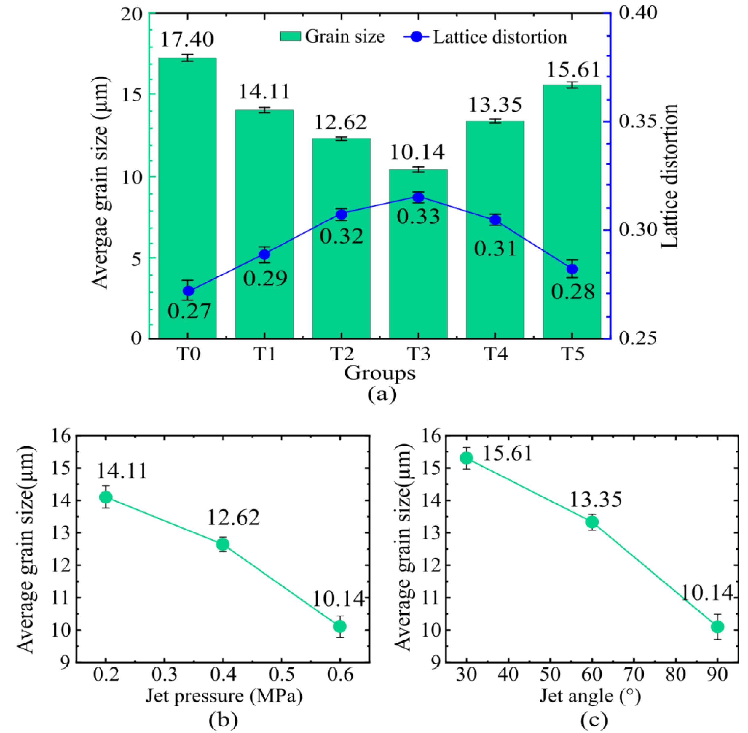
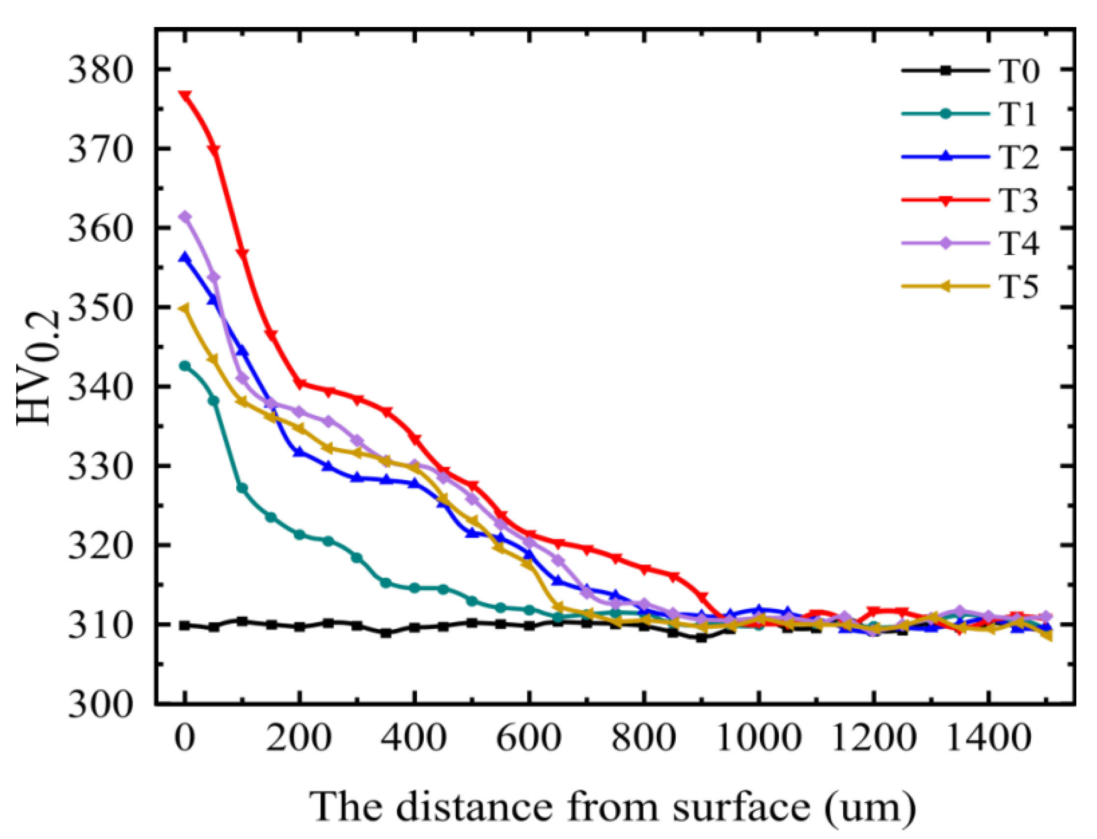
The hardness of the processed surface is a direct reflection of the wear resistance of the sample. As the jet pressure increased from 0.2 MPa to 0.6 MPa, the hardness increased from 310 HV0.2 to 377.6 HV0.2. The hardness rose from 310 HV0.2 to 362.4 HV0.2 and then to 377.6 HV0.2 when the jet angle increased from 30° to 60° and then to 90°. By analyzing the morphology of the processed surface with different jet pressures and angles, it is found that the extent of the grain refinement is positively correlated with the jet pressure and angle. On the one hand, plastic deformation of the surface layer caused grain refinement, and the extent of plastic deformation is positively correlated with jet pressure. Accordingly, the extent of grain refinement is positively correlated with the jet pressure. As for the jet angle, the component of plastic deformation energy in the vertical direction is positively correlated with the jet angle. Accordingly, the extent of grain refinement is also positively correlated with the jet angle. On the other hand, the martensite content in the processed surface of the treated samples was increased. The lattice distortions in the processed surface due to plastic deformation induces retained austenite transformation into martensite, and the martensite content becomes positively correlated with the lattice distortion. The strength-modified grinding technique induces grain refinement in the processed surface of 30CrMnSiA bearing steels and causes retained austenite to transform into martensite by producing lattice distortion, which is the main reason for the rise in the surface hardness of the samples.
A summary of the test results for different jet pressures and angles is shown in
Table 4.
Author Contributions
Conceptualization, X.L., X.C., Z.L. (Zhongwei Liang), T.Z. and Z.L. (Zhaoyang Liu); methodology, X.L., X.C. and Z.L. (Zhongwei Liang); formal analysis, X.C. and Z.L. (Zhaoyang Liu); investigation, X.C. and B.H.; resources, X.L. and Z.L. (Zhongwei Liang); data curation, X.C. and B.H.; writing—original draft preparation, X.C.; writing—review and editing, X.C. and Z.L. (Zhaoyang Liu); supervision, X.L., Z.L. (Zhaoyang Liu) and Z.L. (Zhongwei Liang); project administration, X.L. and Z.L. (Zhongwei Liang); funding acquisition, X.L. and Z.L. (Zhongwei Liang). All authors have read and agreed to the published version of the manuscript.
Funding
The National Natural Science Foundation of China (51975136, 52075109), National Key Research and Development Program of China (2018YFB2000501), the Science and Technology Innovative Research Team Program in Higher Educational Universities of Guangdong Province (2017KCXTD025), Special Research Projects in the Key Fields of Guangdong Higher Educational Universities (2019KZDZX1009), the Science and Technology Research Project of Guangdong Province (2017A010102014), the Industry–University–Research Cooperation Key Project of Guangzhou Higher Educational Universities (202235139), and Guangzhou University Research Project (YJ2021002).
Institutional Review Board Statement
Not applicable.
Informed Consent Statement
Not applicable.
Data Availability Statement
Not applicable.
Conflicts of Interest
The authors declare no conflict of interest.
References
- Lei, Z.; Li, B.; Ni, L.; Yang, Y.; Yang, S.; Hu, P. Mechanism of the crack formation and suppression in laser-MAG hybrid welded 30CrMnSiA joints. J. Mater. Process. Technol. 2017, 239, 187–194. [Google Scholar] [CrossRef]
- Wang, T.; Yu, B.; Wang, Y.; Jiang, S. Effect of beam current on microstructures and mechanical properties of joints of TZM/30CrMnSiA by electron beam welding. Chin. J. Aeronaut. 2021, 34, 122–130. [Google Scholar] [CrossRef]
- Feng, Z.; Zhao, H.; Tan, C.; Zhu, B.; Xia, F.; Wang, Q.; Chen, B.; Song, X. Effect of laser texturing on the surface characteristics and bonding property of 30CrMnSiA steel adhesive joints. J. Manuf. Processes 2019, 47, 219–228. [Google Scholar] [CrossRef]
- Wang, S.; Chen, S.; Li, X.; Wan, L. Microstructures and Mechanical Properties of 30CrMnSiA Steel Joints Welded by Vacuum Electron Beam. In Proceedings of the Robotic Welding, Intelligence and Automation, Shanghai, China, 25–27 October 2014; pp. 571–580. [Google Scholar] [CrossRef]
- Li, N.; Zhang, W.; Xu, H.; Cai, Y.; Yan, X. Corrosion Behavior and Mechanical Properties of 30CrMnSiA High-Strength Steel under an Indoor Accelerated Harsh Marine Atmospheric Environment. Materials 2022, 15, 629. [Google Scholar] [CrossRef]
- Li, F.; Zhao, S.; Zhu, C.; Zhang, P.; Jiang, H. Influence of process parameters on the forming results of large-sized cylindrical parts during counter-roller spinning. J. Adv. Mech. Des. Syst. Manuf. 2022, 16, JAMDSM0009. [Google Scholar] [CrossRef]
- Qu, S.; Lai, F.; Wang, G.; Yuan, Z.; Li, X.; Guo, H. Friction and Wear Behavior of 30CrMnSiA Steel at Elevated Temperatures. J. Mater. Eng. Perform. 2016, 25, 1407–1415. [Google Scholar] [CrossRef]
- Liu, T.; Qi, X.; Shi, X.; Zhang, T.; Zhang, G.; Zhang, J. Crack growth path of 30CrMnSiA steel under variable amplitude multiaxial loading. Int. J. Fatigue 2021, 153, 106502. [Google Scholar] [CrossRef]
- Tan, Z.H.; Guo, Q.; Li, X.; Zhao, Z.P. The Tribological Behaviour of Beryllium Copper Alloy QBe2 against 30CrMnSiA Steel under Sliding Condition. In Proceedings of the Advanced Materials Research, Beihai, China, 23–25 December 2011; pp. 2181–2188. [Google Scholar] [CrossRef]
- Liu, T.; Qi, X.; Shi, X.; Gao, L.; Zhang, T.; Zhang, J. Effect of Loading Frequency Ratio on Multiaxial Asynchronous Fatigue Failure of 30CrMnSiA Steel. Materials 2021, 14, 3968. [Google Scholar] [CrossRef]
- Zhou, J.S.; Zhen, L.; Yang, D.Z.; Li, H.T. Macro- and microdamage behaviors of the 30CrMnSiA steel impacted by hypervelocity projectiles. Mater. Sci. Eng. A 2000, 282, 177–182. [Google Scholar] [CrossRef]
- Fu, Y.; Hu, J.; Shen, X.; Wang, Y.; Zhao, W. Surface hardening of 30CrMnSiA steel using continuous electron beam. Nucl. Instrum. Methods Phys. Res. Sect. B Beam Interact. Mater. At. 2017, 410, 207–214. [Google Scholar] [CrossRef]
- Tang, L.; Yan, M. Microstructure and mechanical properties of surface layers of 30CrMnSiA steel plasma nitrocarburized with rare earth addition. J. Rare Earths 2012, 30, 1281–1286. [Google Scholar] [CrossRef]
- Yan, M.; Wang, Y.; Chen, X.; Guo, L.; Zhang, C.; You, Y.; Bai, B.; Chen, L.; Long, Z.; Li, R. Laser quenching of plasma nitrided 30CrMnSiA steel. Mater. Des. 2014, 58, 154–160. [Google Scholar] [CrossRef]
- Xiao, J.; Liu, X.; Xie, B.; Liu, C.; Zhang, J.; He, Q. Study on the optimal velocity of reinforced grinding of bearing ring raceway. Hydromechatronics Eng. 2014, 42, 56–61+106. [Google Scholar] [CrossRef]
- Liu, X.; Wen, Y.; Liang, Z.; Liao, S.; Ji, W. Effect of Bearing Steel Balls Diameter Ratio for Surface Hardness and Morphology of Bearing Ring in Reinforced Grinding Processing. Mach. Tool Hydraul. 2017, 45, 123–126. [Google Scholar] [CrossRef]
- Liu, X.; Chen, F.; Zhang, C.; Shan, S.; Liao, S. Experiment and Research of Abrasive Ratio Based on Reinforced Grinding Processing. Tool Eng. 2016, 50, 27–30. [Google Scholar] [CrossRef]
- Liu, X.; Zhao, C.; Li, F.; Qin, Z.; Zhou, W.; Chen, F. Analysis of Residual Stress in Bearing Rings of Reinforced Grinding. Modul. Mach. Tool Autom. Manuf. Tech. 2017, 4, 5–8. [Google Scholar] [CrossRef]
- Liu, X.; Qin, Z.; Xiao, J.; Zhao, C.; Chen, Y. Evaluation for Wear Failure of Strengthening Abrasive Based on Image Processing. Bearing 2018, 11, 26–29+60. [Google Scholar] [CrossRef]
- Xiao, J.; Zhao, Z.; Xie, X.; Liang, Z.; Liu, Z.; Liu, X.; Tang, R. Micromorphology, Microstructure, and Wear Behavior of AISI 1045 Steels Irregular Texture Fabricated by Ultrasonic Strengthening Grinding Process. Metals 2022, 12, 1027. [Google Scholar] [CrossRef]
- Xie, X.; Guo, Z.; Zhao, Z.; Liang, Z.; Wu, J.; Liu, X.; Xiao, J. Salt-Fog Corrosion Behavior of GCr15 Steels Treated by Ultrasonic Strengthening Grinding Process. Appl. Sci. 2022, 12, 7360. [Google Scholar] [CrossRef]
- Liu, X.; Wu, Z.; Liang, Z.; Wu, J.; Fan, L.; Geng, C.; Xie, X.; Huang, W.; Wei, S. Effect of Spray Angle on Friction and Corrosion Resistance of GCr15 Bearing Steel in Strengthening Grinding. Mech. Electr. Eng. Technol. 2021, 50, 1–5. [Google Scholar] [CrossRef]
- Xiao, J.; Liu, X.; Liang, Z.; Xiao, Z. Effect of Steel Bead’s Damage on the Surface Roughness and Hardness of Bearing Rings under Strengthen Grinding Processing. Surf. Technol. 2018, 47, 290–295. [Google Scholar] [CrossRef]
- Xiao, J.; Liang, Z.; Huang, J.; Gao, W.; Liu, X.; Chen, Y. Effect of Strengthen Grinding on the Surface Corrosion Resistance of Bearing Ring. Surf. Technol. 2021, 50, 238–244+294. [Google Scholar] [CrossRef]
- Liu, X.; Huang, J.; Liang, Z.; Huang, W.; Zhu, R.; Gao, W.; Xiao, J. Preparation and Properties of the Composite Enhancement Layer of Bearing Ring. World J. Mech. 2020, 10, 139–153. [Google Scholar] [CrossRef]
- Liu, X.; Geng, C.; Ruan, Y.; Liang, Z.; Feng, W.; Fan, L.; Wu, Z.; Wu, J. Effect of Strengthened Grinding Jet Pressure on Stress Corrosion Properties of GCr15 Bearing Steel. Mech. Electr. Eng. Technol. 2022, 51, 6–9+85. [Google Scholar]
- Farhat, Z.N.; Ding, Y.; Northwood, D.O.; Alpas, A.T. Effect of grain size on friction and wear of nanocrystalline aluminum. Mater. Sci. Eng. A 1996, 206, 302–313. [Google Scholar] [CrossRef]
- Zhang, H.; Dong, X.; Wang, Q.; Li, H. Micro-bending of metallic crystalline foils by non-local dislocation density based crystal plasticity finite element model. Trans. Nonferrous Met. Soc. China 2013, 23, 3362–3371. [Google Scholar] [CrossRef]
- Khun, N.W.; Trung, P.Q.; Butler, D.L. Mechanical and Tribological Properties of Shot-Peened SAE 1070 Steel. Tribol. Trans. 2016, 59, 932–943. [Google Scholar] [CrossRef]
- Nespolo, M.; Souvignier, B. Application of the crystallographic orbit analysis to the study of twinned crystals. The example of marcasite. Cryst. Res. Technol. 2015, 50, 442–450. [Google Scholar] [CrossRef]
- Wang, F.; Hazeli, K.; Molodov, K.D.; Barrett, C.D.; Al-Samman, T.; Molodov, D.A.; Kontsos, A.; Ramesh, K.T.; El Kadiri, H.; Agnew, S.R. Characteristic dislocation substructure in {10(1)over-bar2} twins in hexagonal metals. Scr. Mater. 2018, 143, 81–85. [Google Scholar] [CrossRef]
- Niho, T.; Nambu, S.; Nagato, K.; Nakao, M. Classification of Twin Arrangements in Butterfly Martensite Grains and Analysis of Relationship between Twin Arrangement and Butterfly Wing Angle in Medium-Carbon Steel. ISIJ Int. 2020, 60, 2075–2082. [Google Scholar] [CrossRef]
- Ma, B.; Fu, L.; ShangGuang, B.; Du, S.; Mao, Y.; Yue, Y.; Zhang, Y. Friction and wear Properties of Gcr15 and G20CrNi2Mo Bearing Steels under High Temperture Lubrication. Lubriction Eng. 2022, 47, 62–68. [Google Scholar] [CrossRef]
- Xiong, X.; Chen, J.; Yao, P.; Li, S.; Huang, B. Friction and wear behaviors and mechanisms of Fe and SiO2 in Cu-based P/M friction materials. Wear 2007, 262, 1182–1186. [Google Scholar] [CrossRef]
- Yan, W.; Liu, J.; Wen, S.; Yue, Z. Energy conversion and residual stress distribution in shot peening process. J. Vib. Shock 2011, 30, 139–142+191. [Google Scholar] [CrossRef]
Figure 1.
Parameter setting and schematic illustration of the treatment process in SMGT.
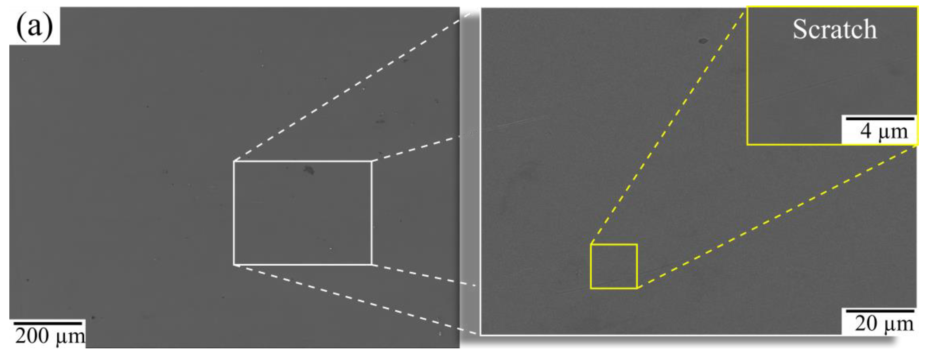
Figure 2.
SEM micrograph of surface microstructure of samples. (a) control group T0; (b) group T1; (c) group T2; (d) group T3; (e) group T4; (f) group T5.
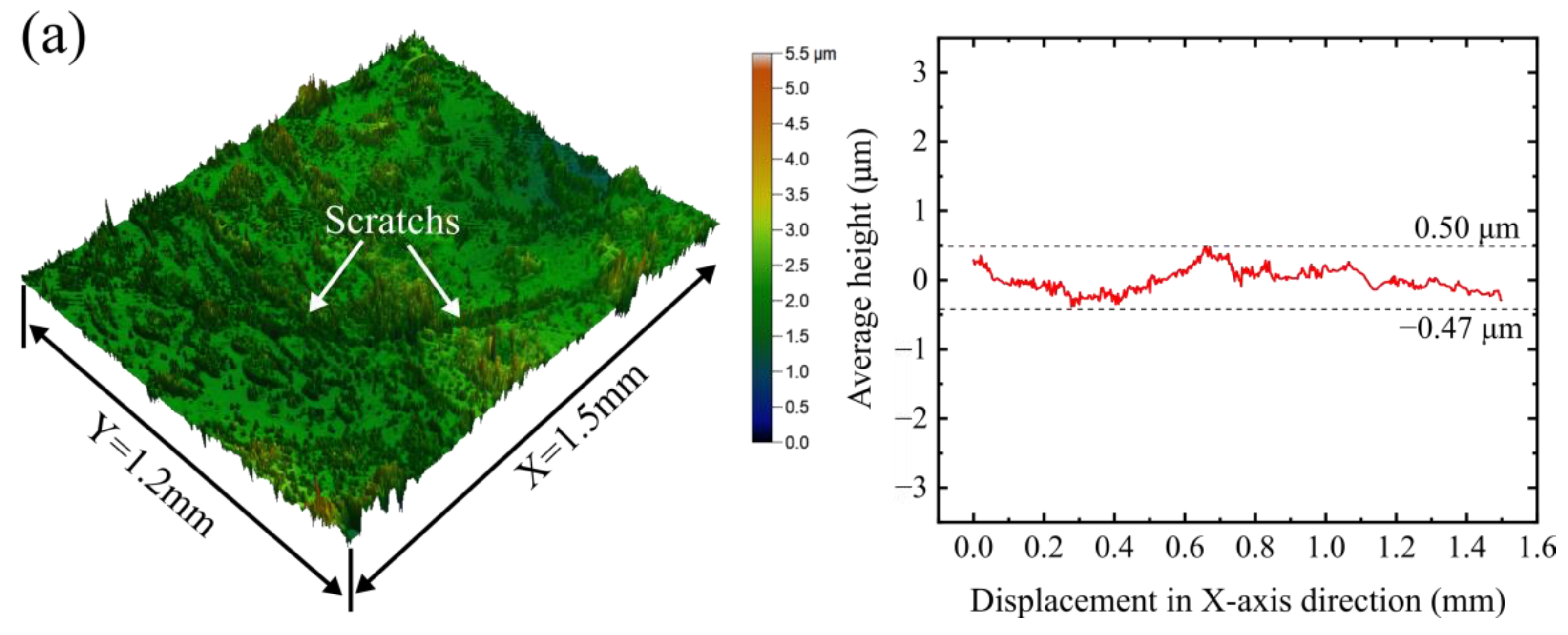
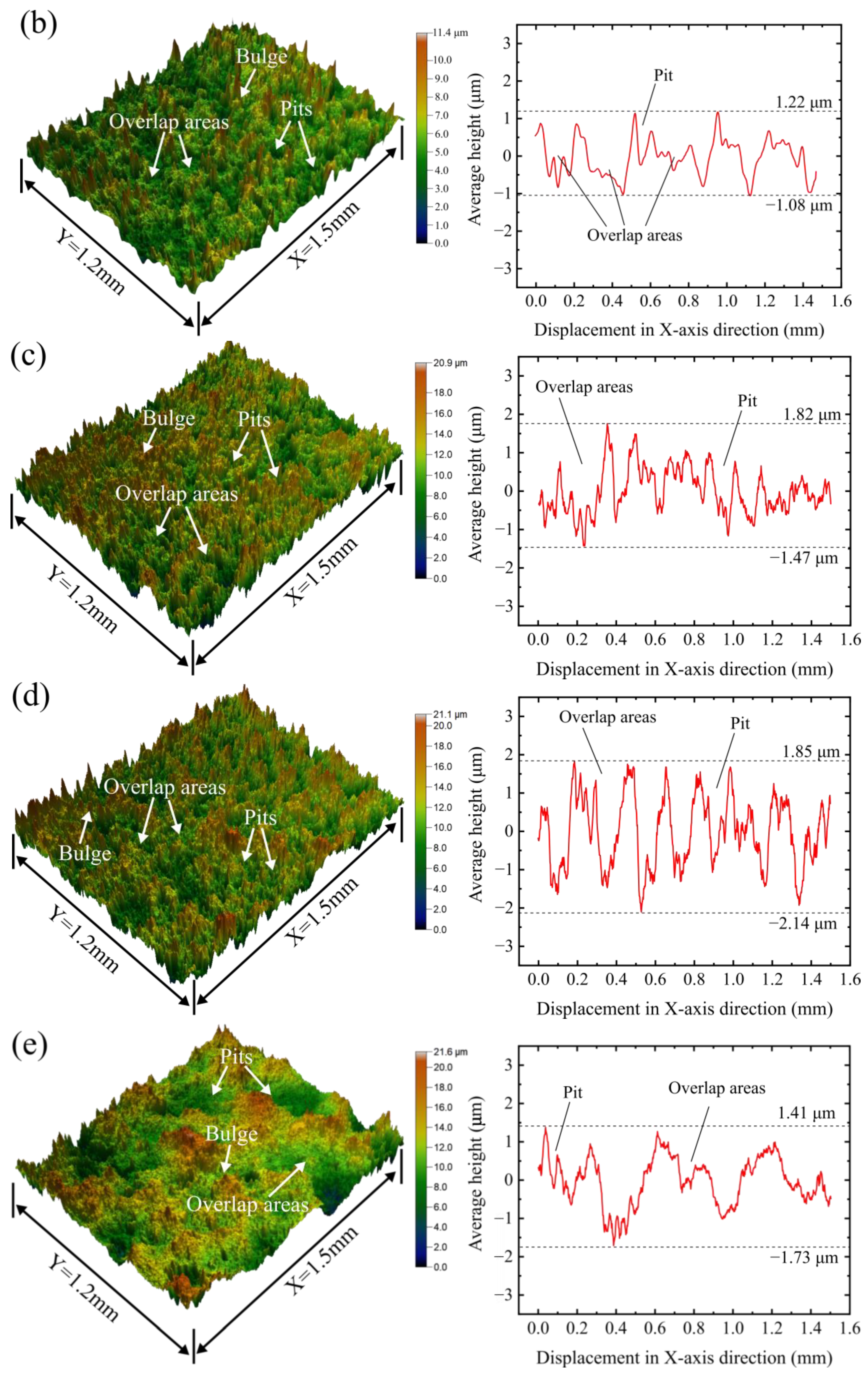
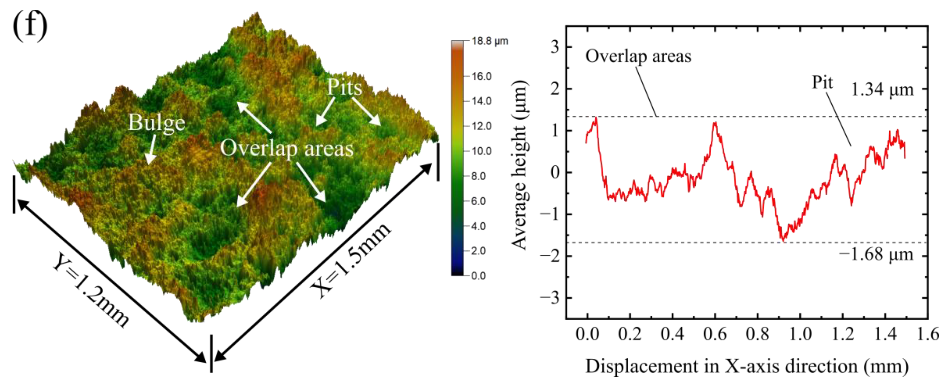
Figure 3.
Three-dimensional morphology and two-dimensional profile of specimens: (a) control group T0; (b) group T1; (c) group T2; (d) group T3; (e) group T4; (f) group T5.
Figure 4.
(a) Two-dimensional profile of pits of specimens; (b) Width and depth of pits of specimens; (c) Height of bulge around pits of specimens.
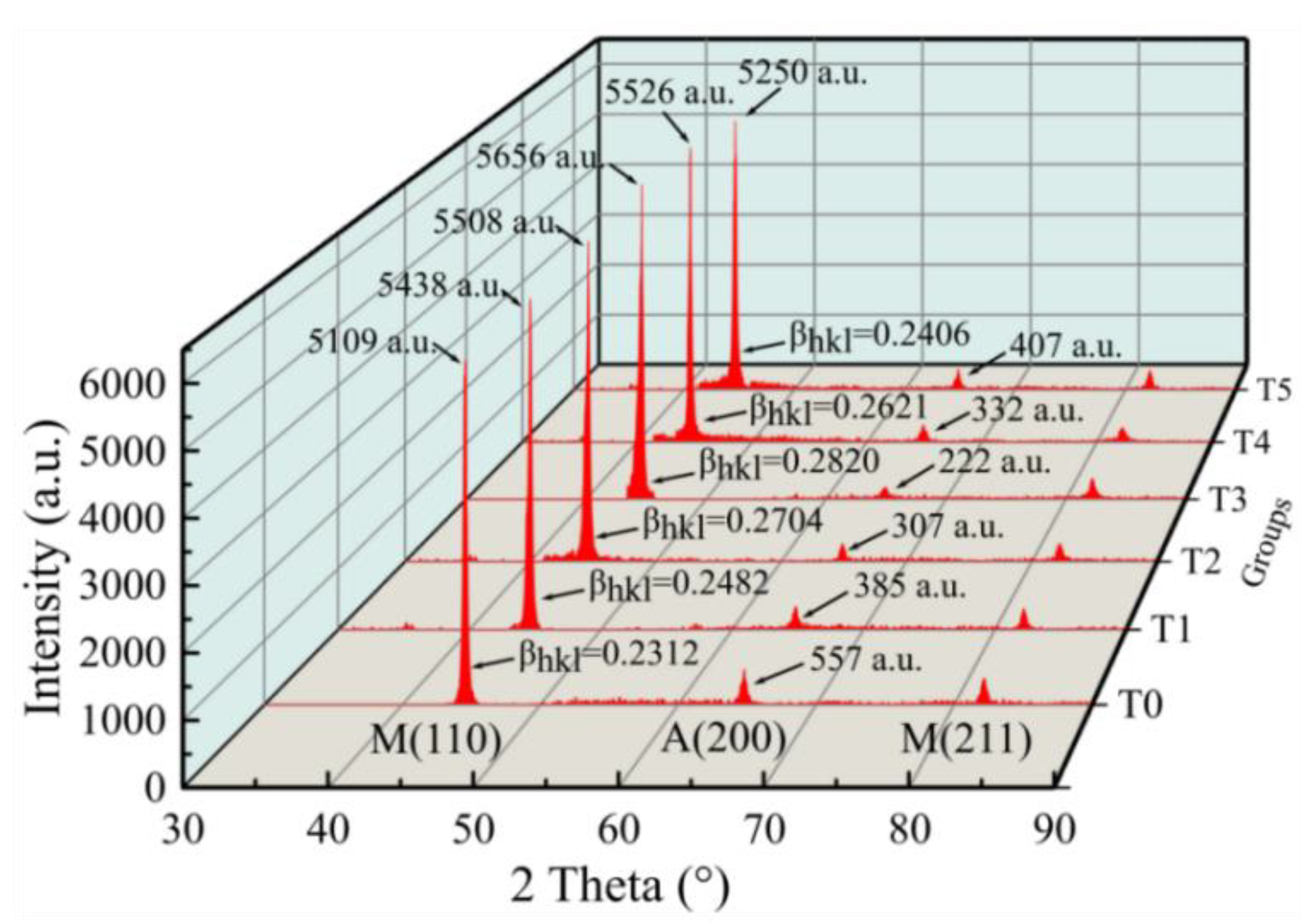
Figure 5.
X-ray diffraction pattern on the specimen surface layer of groups T0–T5.
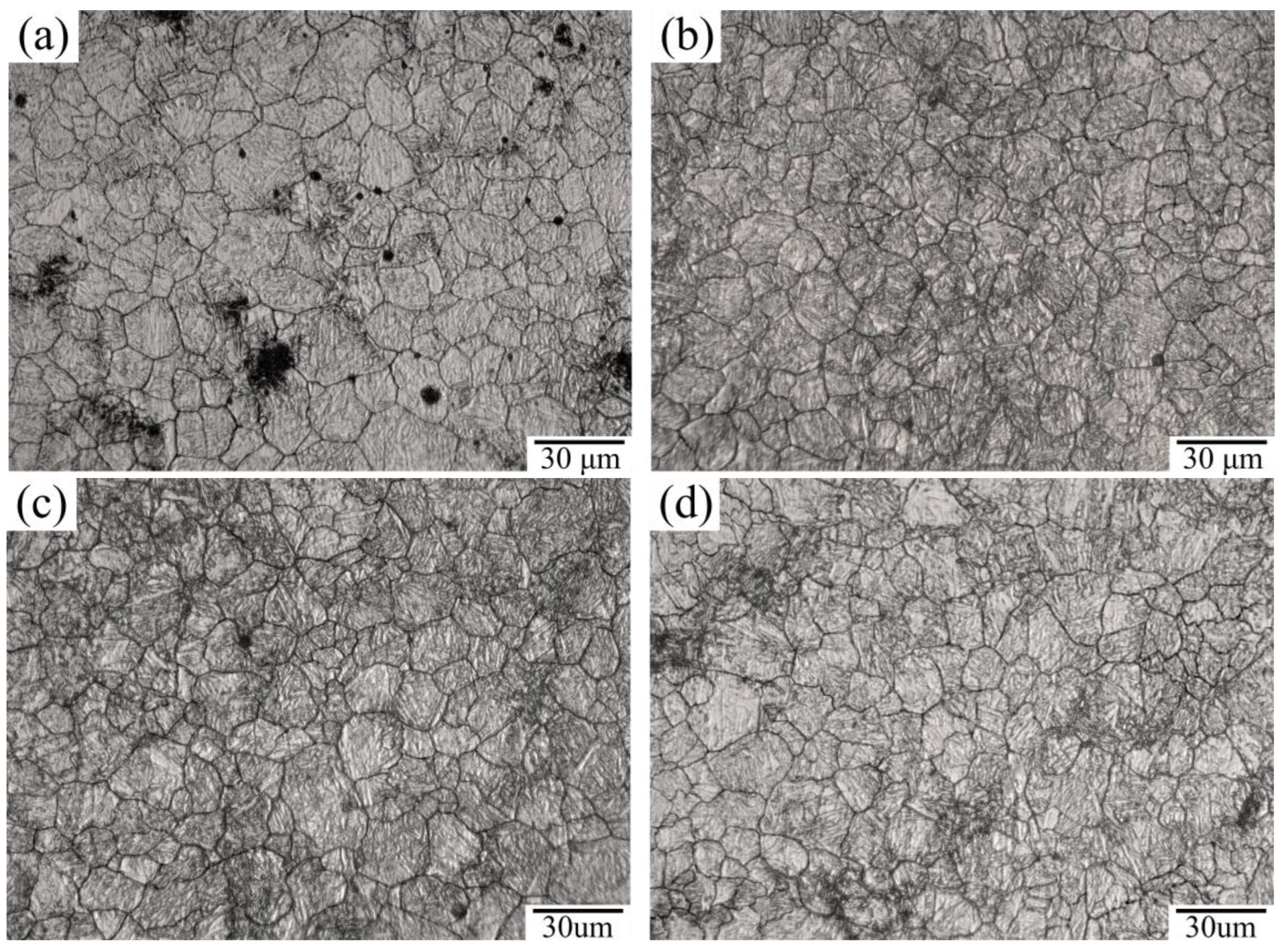
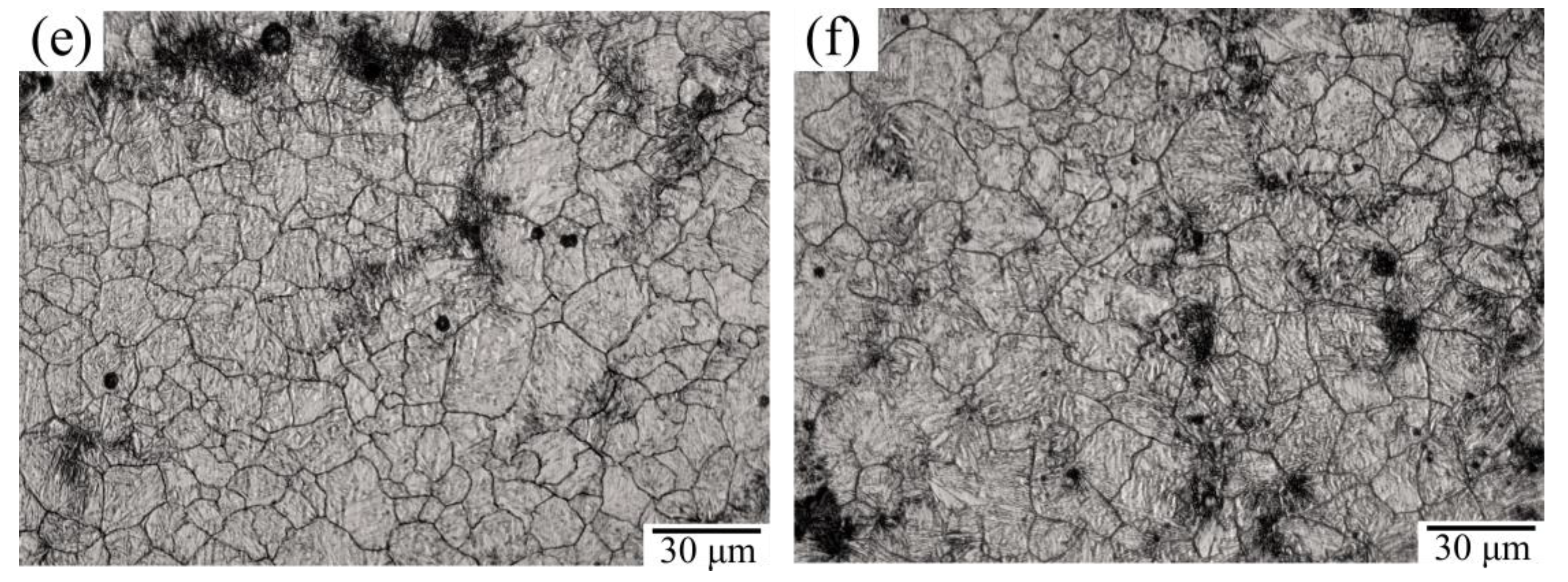
Figure 6.
Grain size etching diagram. (a) Control group T0; (b) group T1; (c) group T2; (d) group T3; (e) group T4; (f) group T5.
Figure 7.
(a) The average grain size and lattice distortion of specimens; (b) Variation of average grain size with jet pressure; (c) Variation of average grain size with jet angle.
Figure 8.
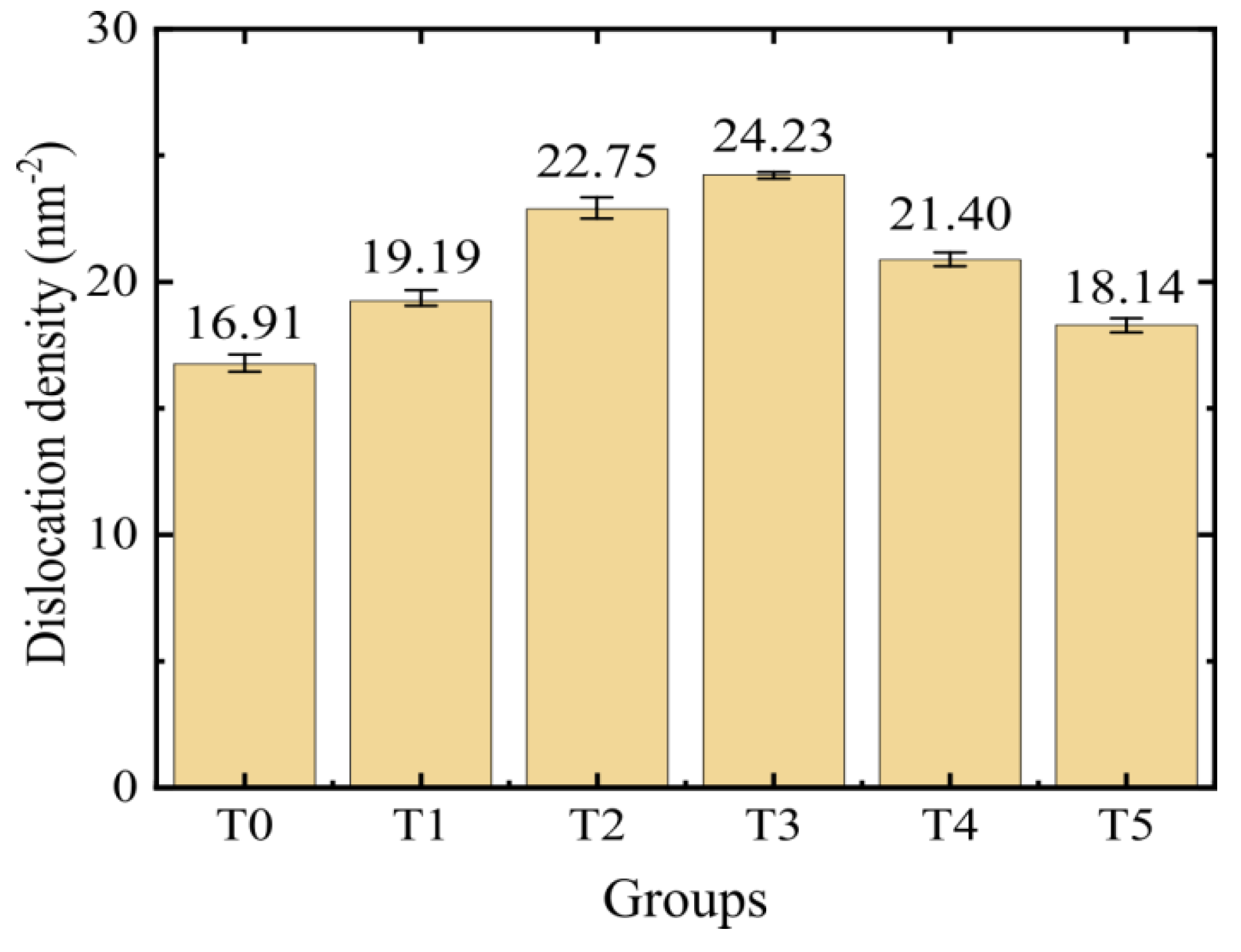
Dislocation density in the surface microstructure of specimens.
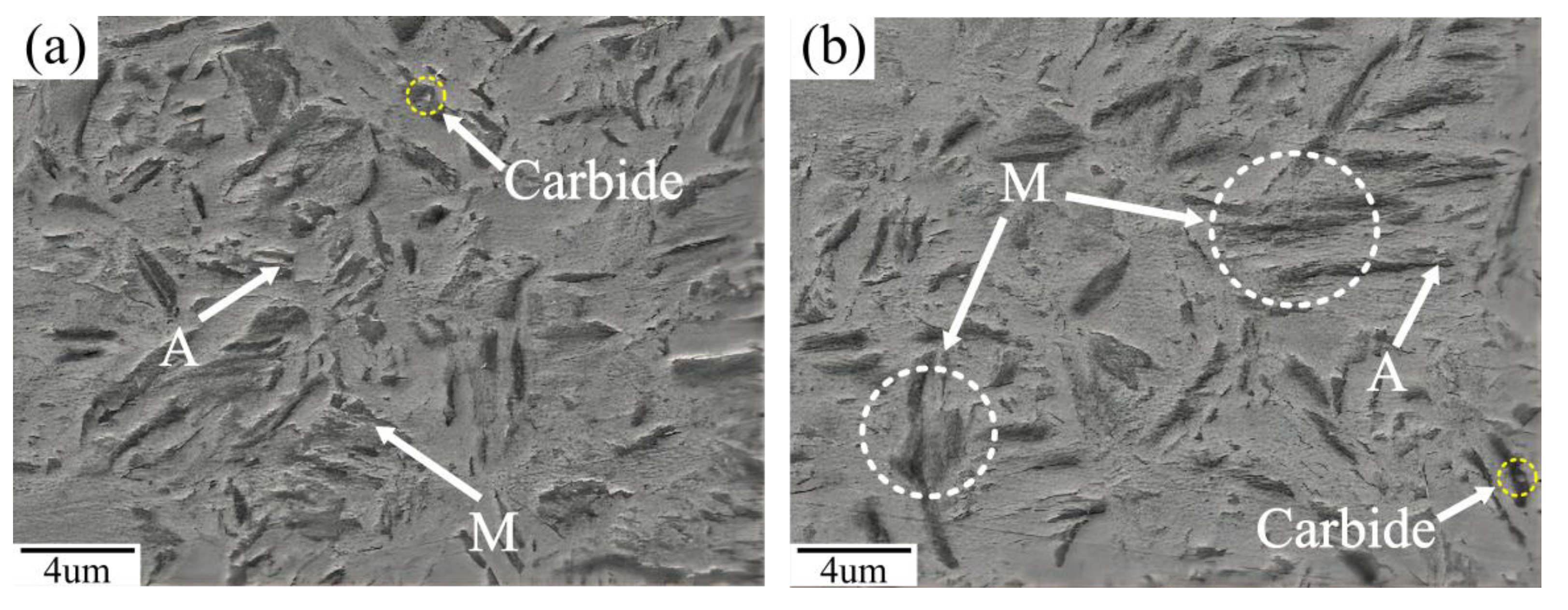
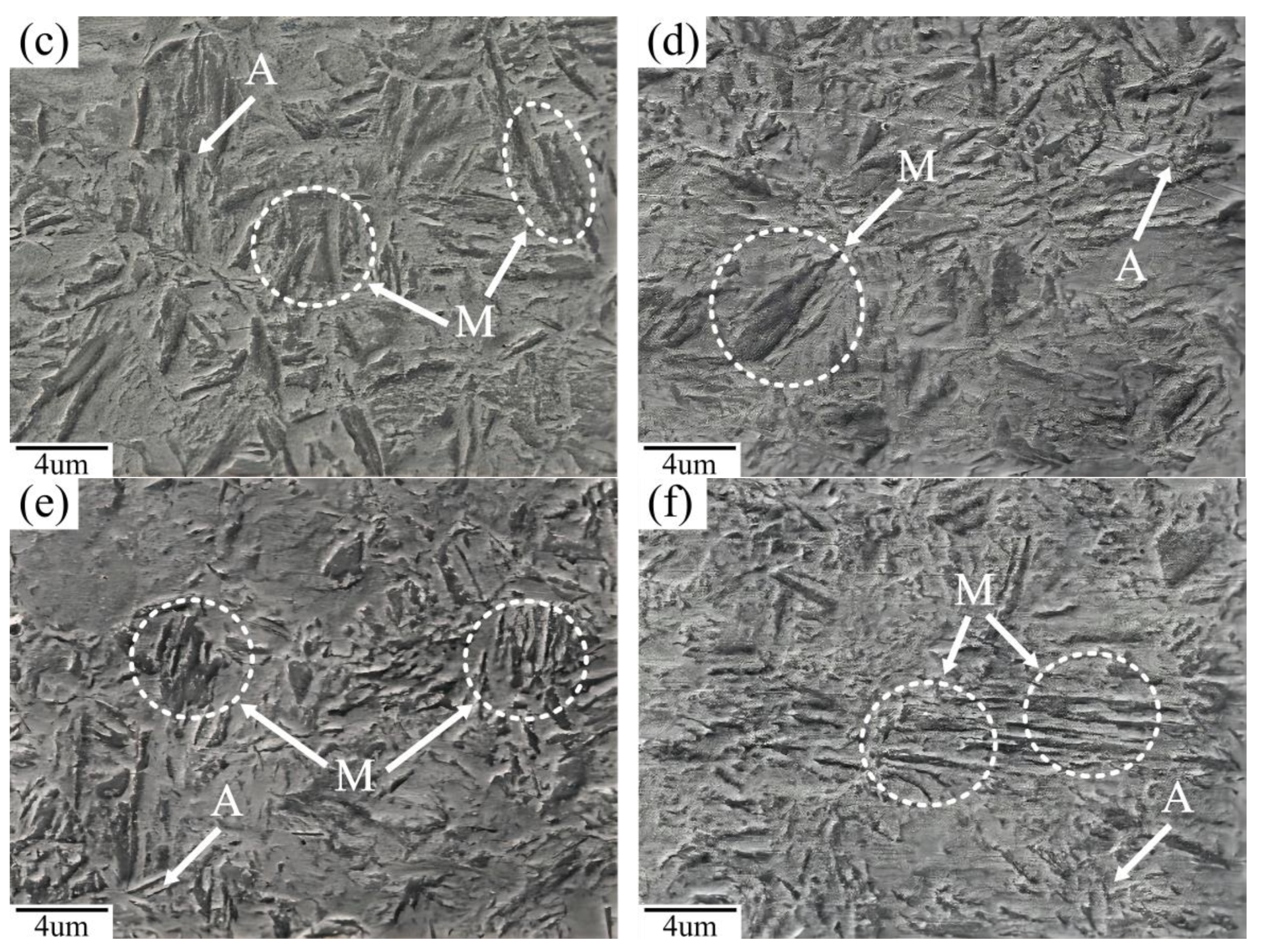
Figure 9.
SEM image of processed surface. (a) control group T0; (b) group T1; (c) group T2; (d) group T3; (e) group T4; (f) group T5.
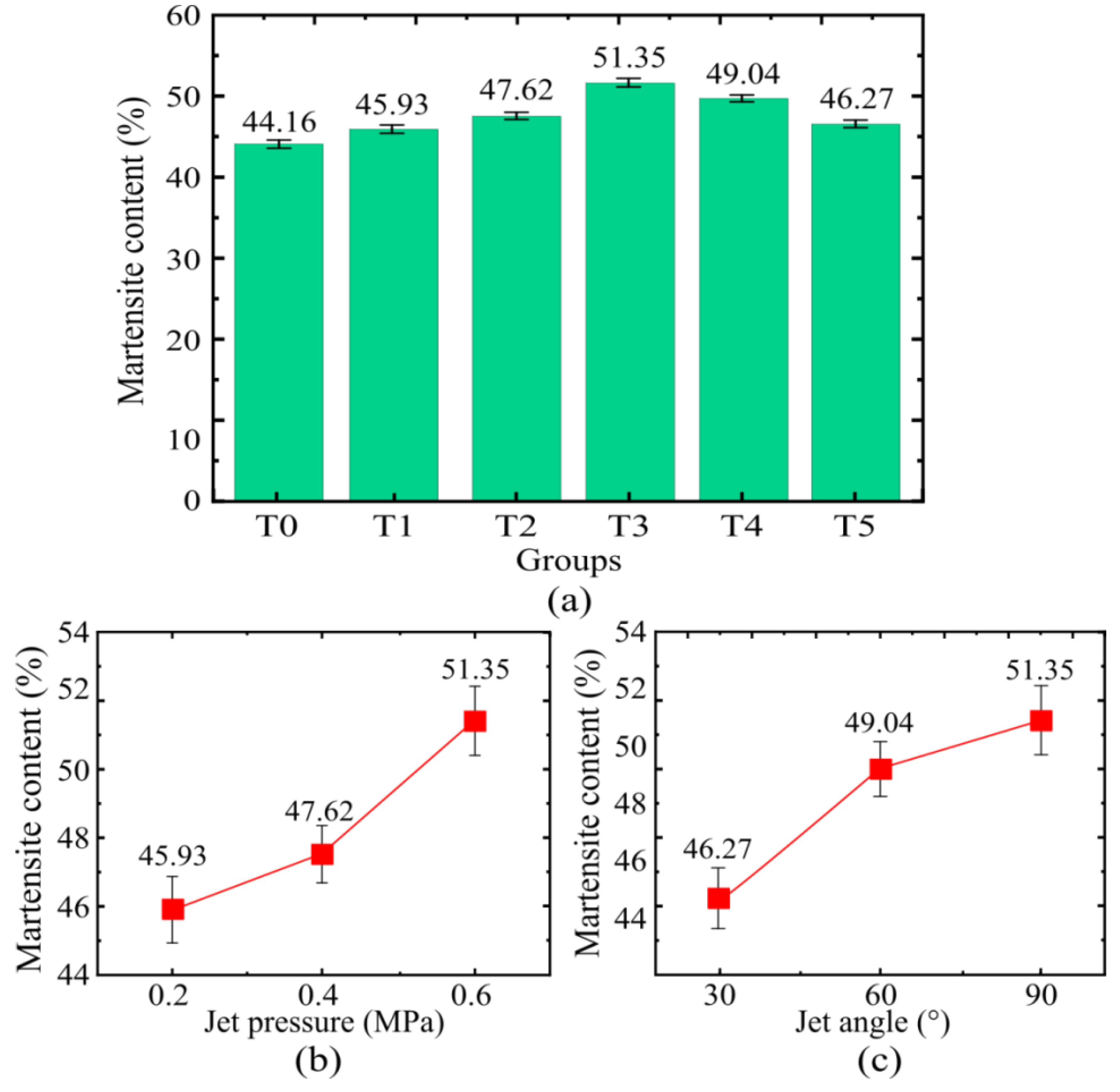
Figure 10.
(a) Martensite and retained austenite content of processed surface; (b) Martensite content changes with jet pressure; (c) Martensite content changes with jet angle.
Figure 11.
Microhardness profiles in cross-sections of samples.
Figure 12.
Schematic view of impact principle.
Figure 13.
(a) Schematic view of impact and micro-cutting; (b) Schematic view of the two-dimensional profile.
Figure 14.
(a) Schematic view of the effect of jet pressure on pits; (b) Schematic view of the effect of jet angle on pits.
Table 1.
Chemical composition of 30CrMnSiA Steel (wt. %).
| Material | Cr | C | Mn | Si | S | P | Fe |
|---|
| 30CrMnSiA | 0.96 | 0.37 | 0.94 | 1.06 | ≤0.01 | ≤0.01 | Bal. |
Table 2.
Composition ratio of the strengthened grinding fluids.
| Composition | Chemical Formula | Weight (%) |
|---|
| Borax | Na2B4O7·10H2O | 25 |
| Triethanolamine | C6H15NO3 | 10 |
| Benzotriazole | C6H5N3 | 13 |
| Distilled water | H2O | 50 |
| Others | None | 2 |
Table 3.
Parameters of single-factor test.
| Group | Jet Pressure (MPa) | Jet Angle (°) | Jetting Distance (mm) | Process Time (s) |
|---|
| T0 | none | none | none | none |
| T1 | 0.2 | 90 | 90 | 900 |
| T2 | 0.4 | 90 |
| T3 | 0.6 | 90 |
| T4 | 0.6 | 60 |
| T5 | 0.6 | 30 |
Table 4.
Summary of test results at different jet pressures and angles.
| | T0 | T1 | T2 | T3 | T4 | T5 |
|---|
| Jet Pressure (MPa) | None | 0.2 | 0.4 | 0.6 | 0.6 | 0.6 |
| Jet angle (°) | None | 90 | 90 | 90 | 60 | 30 |
| Pit width (μm) | None | 123 | 166 | 221 | 248 | 273 |
| Pit height (μm) | None | 1.57 | 2.64 | 3.52 | 1.71 | 1.18 |
| Bulge height (μm) | None | 0.62 | 1.41 | 1.73 | 0.64 | 0.48 |
| Average grain size (μm) | 17.40 | 14.11 | 12.62 | 10.14 | 13.35 | 15.61 |
| Martensite content (%) | 44.16 | 45.93 | 47.62 | 51.35 | 49.04 | 46.27 |
| Surface hardness (HV0.2) | 310 | 344.2 | 356.8 | 377.6 | 362.4 | 350.1 |
| Publisher’s Note: MDPI stays neutral with regard to jurisdictional claims in published maps and institutional affiliations. |
© 2022 by the authors. Licensee MDPI, Basel, Switzerland. This article is an open access article distributed under the terms and conditions of the Creative Commons Attribution (CC BY) license (https://creativecommons.org/licenses/by/4.0/).


 ,
, 
