Article

Variation Law of Thickness Fraction of Three-Laminated Aluminum Composite Plate by Solid–Liquid–Solid and Liquid–Solid–Liquid Twin-Roll Casting

1
National Engineering Research Center for Equipment and Technology of Cold Strip Rolling, Yanshan University, Qinhuangdao 066004, China
2
Hebei Light Structural Equipment Design and Manufacturing Technology Innovation Center, Yanshan University, Qinhuangdao 066004, China
*
Author to whom correspondence should be addressed.
Metals 2022, 12(10), 1710; https://doi.org/10.3390/met12101710
Submission received: 21 July 2022 / Revised: 17 September 2022 / Accepted: 9 October 2022 / Published: 13 October 2022

Abstract

:
Solid–liquid–solid twin-roll casting (SLS-TRC) and liquid–solid–liquid twin-roll casting (LSL-TRC) are two processes for manufacturing three-laminated aluminum composite plates by using solid–liquid cast-rolling composite technology. In order to study the variation law of thickness fractions, a 1060/3003/1060 three-laminated aluminum composite plate was taken as the manufacturing product, and the thickness of the solid strip was used as the variable. Based on the “uactive” user subroutines of MSC.MARC software, the 2D thermomechanical coupling models of SLS-TRC and LSL-TRC were established respectively, and the thickness variation law of the solid strip under the two processes was obtained and verified by experiments. Finally, the recommended process was given according to the target thickness fraction. The results show that with an increase in the cladding thickness, the KISS point (complete freezing point of molten metal) height of the SLS-TRC process increases, the coordinated deformation position decreases relative to the KISS point, and the strain increases. In the LSL-TRC process, as the thickness of the core increases, KISS point height increases, the coordinated deformation position decreases relative to the KISS point, and the strain decreases. The formation process of the composite interface of the two processes is consistent with the N. Bay theory. Finally, through the comparison of cast-rolling forces, it was found that when manufacturing a three-laminated aluminum composite plate with a relatively small thickness fraction (the thickness fraction is less than 30%), the SLS-TRC process requires less load; when the thickness fraction of the three-laminated aluminum composite plate is large (the thickness fraction is greater than 30%), the load required for the manufacturing of the LSL-TRC process is small. The results of this research can provide practical guidance for the manufacturing of three-laminated metal matrix composite panels.

1. Introduction

Three-laminated metal composite plates are composed of two or three metal components with different physical and mechanical properties, which form a combination at the interface through composite technology, giving the composite plate the excellent properties of each component and making up for the lack of performance of a single component. They are widely used in aerospace, petrochemicals, transportation, and other fields [1]. At present, the manufacturing technologies of three-laminated metal composite plates mainly include the explosive welding method [2], the direct chill casting method [3], the roll bonding method [4,5], the powder-in-tube method [6], etc. However, in recent years, cast-rolling composite technology has become the key development direction of the industry because of its advantages of high efficiency, short process, low energy consumption, low cost, safety, green nature, etc. It has received extensive attention from scholars from all over the world [7,8,9,10].
The solid–liquid cast-rolling composite technology of three-laminated metal composite plates can be divided into two processes according to the state of the components: the solid–liquid–solid twin-roll casting process (SLS-TRC) and the liquid–solid–liquid twin-roll casting process (LSL-TRC). In the SLS-TRC process, the metal in the middle layer is liquid, and the metals on both sides are solid. J.H. Bae [11] used a Mg-6Zn-3Al-1Mn magnesium alloy as the casting melt and an aluminum plate as the cladding on both sides, and manufactured an Al/Mg/Al three-laminated composite plate via SLS-TRC. Through research, it was found that there is a Mg17Al12 brittle phase at the interface. After annealing, a Mg2Al3 brittle phase is formed at the interface. Warm rolling of the annealed composite plate can improve the formability of the composite plate. J. Park [12] used an AZ31 magnesium alloy as the casting melt and a 5052 aluminum alloy strip as the cladding on both sides to manufacture an Al/Mg/Al three-laminated composite plate. It was found that the appearance of brittle phases of Mg17Al12 and Mg2Al3 is inevitable, but the thickness of the brittle phases can be appropriately increased to improve the bonding strength of the composite interface and the tensile properties of the composite plate. J.J. Xu [13] used a 3003 aluminum alloy as the casting melt and a 0.4 mm-thick titanium alloy TA2 as well as copper alloy T2 with the same thickness as the cladding on both sides to manufacture a Ti/Al/Cu three-laminated composite plate, and studied the influence of annealing and the cold rolling process on its interface structure and properties. R.D. Zhao [14] used a 3003 aluminum alloy as the casting melt and 0.5 mm-thick 1060 aluminum alloy strips as the cladding on both sides, respectively using steel rolls and copper rolls to manufacture 1060/3003/1060 three-laminated composite aluminum plates, and studied the influence of roll sleeve materials on the temperature field of the SLS-TRC process. In addition, the LSL-TRC process has also attracted the attention of researchers. In the LSL-TRC process, the metal in the middle layer is solid, and the metals on both sides are liquid. C. Ji [15] used an Invar plate as the core and Cu as the casting melt on both sides to manufacture a Cu/Invar/Cu three-laminated composite plate, and studied the influence of various process parameters and established a process window prediction model. Both of these processes are used in practice. However, the comparison of these two processes and how to select the appropriate cast-rolling process to manufacture the target three-laminated metal composite plate are less researched at present.
In view of this, this research provides a reference for selecting an appropriate cast-rolling process by comparing the temperature distribution and deformation degree of the SLS-TRC process and LSL-TRC. To facilitate the comparison of the two processes, the same composite material was used as the manufacturing target. In previous research, metals with a lower melting point were often used as the molten to be cast, avoiding the melting of the metal with a higher melting point to the other metal. However, in this research, different components are required to be cast as molten separately, so the melting points of the components need to be as close as possible. The melting point of 1060 aluminum alloy is 646~657 °C, and the melting point of 3003 aluminum alloy is 643~653 °C. The melting points of the two materials are similar, which meets the needs of the research. Additionally, the 1060/3003/1060 composite plate, similar to the 1100/3004/1100 composite plate that has been used in the manufacturing of air separation plants can be applied in engineering and has research value. In the research, using MSC.MARC software (2018.0.0, MSC Software Corporation, Los Angeles, CA, USA), a 2D thermomechanical coupling model was established. By changing the thickness of the solid aluminum alloy component at the inlet of the cast-rolling zone, the variation law of the thickness fraction of the solid aluminum alloy component was obtained, which was verified by experiments, and the evolution process of the composite interface was explored. Finally, the recommended cast-rolling process was provided according to the target thickness fraction, which provides practical guidance for the manufacturing of three-laminated metal composite plates.

2. Experimental Materials and Methods

2.1. Manufacture Process

The SLS-TRC and LSL-TRC processes of three-laminated aluminum composite plates in this research are shown in Figure 1. Both processes were carried out on a Φ 160 mm × 150 mm vertical twin-roll casting mill, and different delivery systems were used to switch between the SLS-TRC process and the LSL-TRC process. In the SLS-TRC process the cladding aluminum alloy strips on both sides and the molten core aluminum alloy are fed into the roll gap together for casting and rolling, as shown in Figure 1a, and in the LSL-TRC process the core aluminum alloy plate and the molten cladding aluminum alloy on both sides are fed into the roll gap together for casting and rolling, as shown in Figure 1b. Since the melting point of the 1060 aluminum alloy is close to that of the 3003 aluminum alloy, the casting temperature of the liquid phase is higher than the solidus temperature of the solid phase, such that there is a possibility that the solid-phase aluminum alloy is melted by the liquid-phase aluminum alloy. However, the heat transfer process of the cast-rolling zone can be controlled by adjusting the process parameters, such as the casting speed, liquid-phase casting temperature, and solid-phase preheating temperature, so as to realize the composite manufacturing of three-laminated aluminum composite plates via solid–liquid cast-rolling composite technology.

2.2. Experimental Materials

The chemical compositions of Al1060 and Al3003 are shown in Table 1. In SLS-TRC, the cladding Al1060 is solid-state, which is an Al1060 cold-rolled strip, and the core Al3003 is liquid-state, which is obtained by melting an Al3003 rod; in LSL-TRC, the cladding aluminum Al1060 is liquid-state, which is obtained by melting an Al1060 ingot, and the core Al3003 is solid-state, which is an Al3003 cold-rolled plate.
The thermophysical parameters of the 1060 aluminum alloy are shown in Table 2; the solidification interval is 646~657 °C, and the latent heat of solidification is 393 kJ/kg [16,17]. The flow stress can be calculated by Equation (1), which provides liquid flow stress of the 1060 aluminum alloy [18].
Table 2. Thermophysical properties of 1060 aluminum alloy.
Temperature (°C)Density (g/cm3)Specific Heat (J/(kg·K))Heat Conductivity (W/(m·K))
2272.719997236
3272.7191040231
4272.7191080225
5272.7191149218
6272.7191231210
6462.7191264208
6572.368117690.9
6702.368117791.4
7102.368117793
σ ¯ = { 2.37 × 10 8 ε ˙ 0.8733 exp ( 0.019 ( t + 273 ) ) t 600   3.71 × 10 7 ε ˙ 0.6707 exp ( 0.017 ( t + 273 ) ) 500   < t 600   9.161 × 10 3 sinh 1 ε ˙ 0.043 exp ( 0.0069 ( t + 273 ) ) 300   < t 500   2.356 × 10 3 ε ˙ 0.5345 exp ( 0.0041 ( t + 273 ) ) t 300  
t is the deformation temperature, °C; σ ¯ is the flow stress, MPa; and ε ˙ is the strain rate, s−1.
The solidification interval of the 3003 aluminum alloy is 643~653 °C, the density is 2.73 g/cm3, the latent heat of solidification is 373 kJ/kg, the specific heat capacity is 879.1 J/(kg·K), the solid-phase thermal conductivity is 193 W/(m·K), and the liquid-phase thermal conductivity is 96.5 W/(m·K). The flow stress is shown in Figure 2, which provides liquid flow stress of the 3003 aluminum alloy [19].
The material of casting rolls is 42CrMo, and the thermophysical parameters can be read from the MSC.MARC material database, as shown in Table 3.

3. Solid–Liquid–Solid Twin-Roll Casting Process

3.1. Thermal Mechanical Coupling Calculation Model of SLS-TRC Process

In order to explore the effect of cladding thickness on the coordinated deformation of three-laminated aluminum composite plates in the process of SLS-TRC, based on the “uactive” user subroutines of MSC.MARC, 2D thermomechanical coupling models of SLS-TRC were established. The process parameters of the SLS-TRC process are shown in Table 4. During the modeling process, in order to reduce the interference of unnecessary factors, the following assumptions were made: (1) The casting roll is a thermally conductive rigid body, there is no thermal deformation and plastic deformation during the cast-rolling process, it rotates at a constant speed, and the contact heat transfer coefficient between the casting roll sleeve and the cooling water in the roll is constant. (2) In the cast-rolling zone, the heat transfer of the aluminum melt, the aluminum strips, and the casting rolls is uniform along the transverse direction (TD), the rolling force is evenly distributed in the axial direction of the casting rolls, and the cast-rolling forming process can be simplified as a plane strain problem.
In past research, since the deformation of the metal in the cast-rolling zone above the KISS point is mainly manifested by flow, the driving force required for the flow of molten metal is smaller than that of the solid metal deformation. So that this part is usually ignored when calculating the load in the cast-rolling zone, resulting in the calculated results being smaller than the experimental results. However, the flow stress of the molten metal is concluded in this model, and the flow of the molten metal is equivalent to the plastic deformation of the molten metal so that the load required for the deformation of the cast-rolling zone above the KISS point can be calculated, which includes the load of the molten metal flow and the solidified layer deformation. This will bring the calculated results of the model with regard to cast-rolling loads closer to the experimental results.
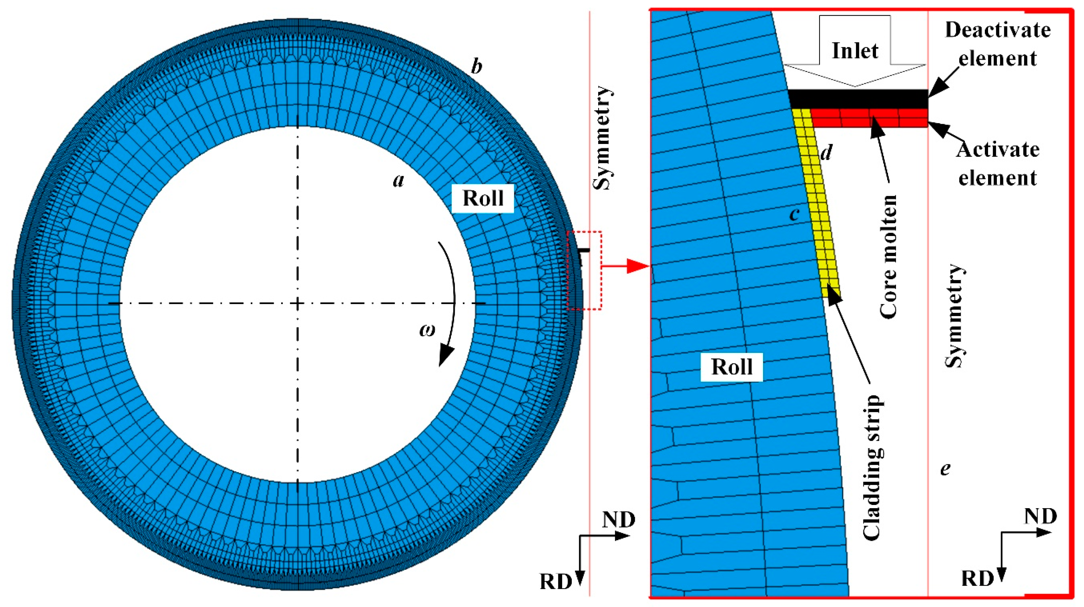
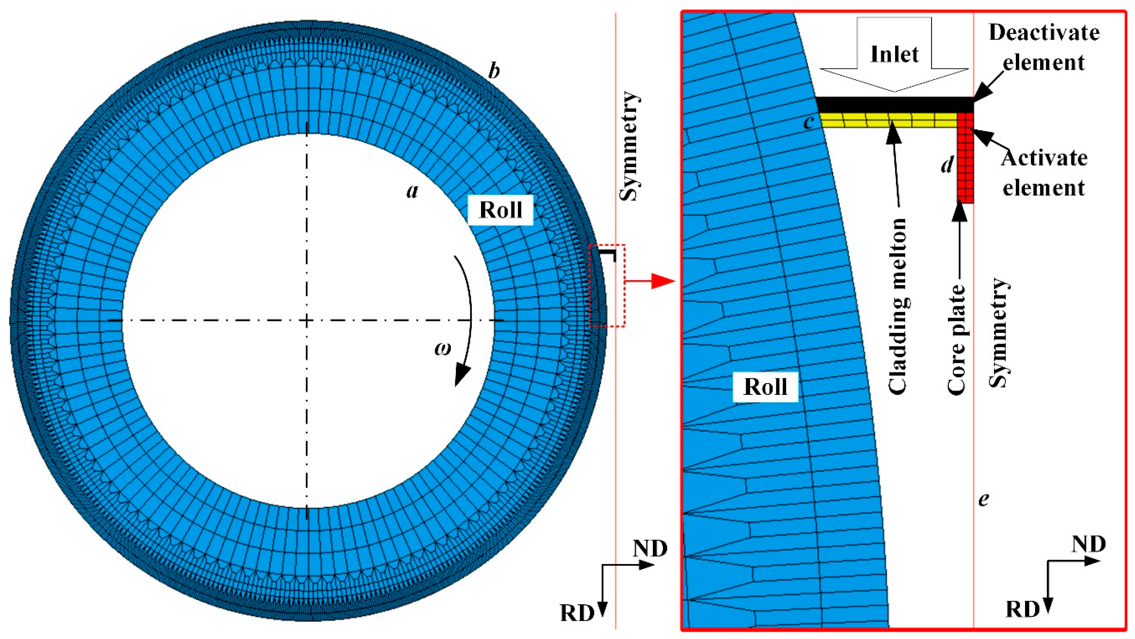
Since the SLS-TRC process is a symmetric model in terms of geometric structure and boundary conditions, the calculation scale can be greatly reduced by using the 1/2 model. The grid division is shown in Figure 3, and the calculation area is divided into one casting roll, one clad aluminum strip, and a 1/2 core aluminum melt. In order to simulate the process that the clad aluminum strip and the core aluminum melt continue to enter the cast-rolling zone and continue to increase the mass and volume, the “uactive” user subroutines are used to divide the elements of the clad aluminum strip and the core aluminum melt into activate elements and deactivate elements. The deactivate elements are to divide a large number of grids in a small range at the inlet of the cast-rolling zone. During the calculation, only the activate elements are calculated, and the deactivate elements are not calculated. With the progress of the cast-rolling, the deactivate elements at the inlet of the cast-rolling zone are gradually transformed into activate elements to be calculated, simulating the process of the cladding aluminum strip and the core aluminum melt entering the cast-rolling zone continuously.
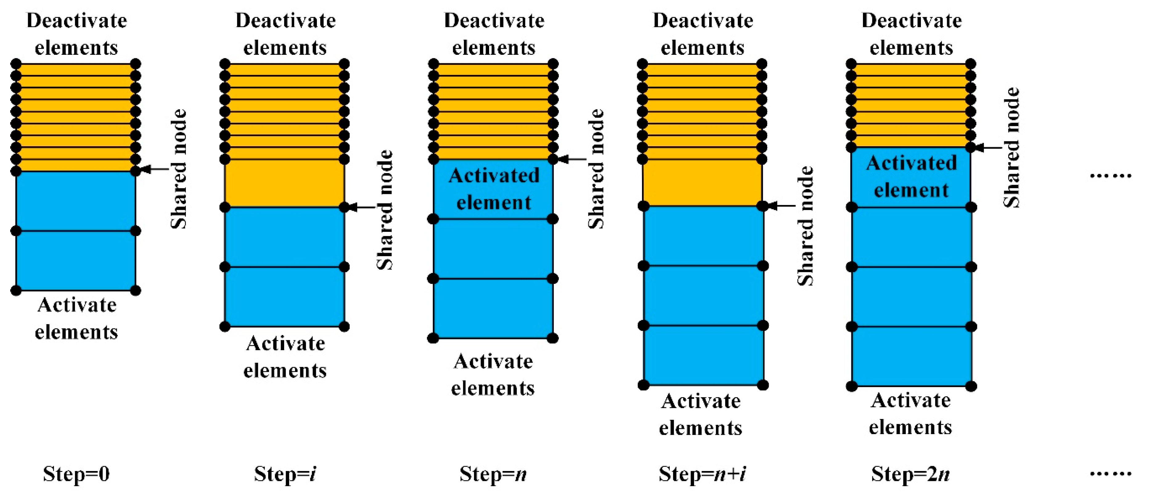
The process of gradually transforming the deactivate elements into the activate elements is shown in Figure 4. When the number of calculation steps is zero, the activate elements and the deactivate elements share the nodes. With an increase in the calculation steps number, when the number of calculation steps is i, the activate elements are gradually moved downward by the driving force of the casting roll, which drives the shared nodes to move at the same time. When the calculation steps number reaches the deactivate element activation period n, the deactivate element that shares the node with the activate element is activated, and the new activate element is given initial condition parameters such as load, mass, node temperature, and thermal boundary conditions to be calculated. At the same time, the shared nodes are the shared nodes of the newly activated element and the deactivate element. As the number of calculation steps increases, the newly activated element also moves, and the shared nodes move at the same time. When the number of calculation steps reaches the next deactivate element activation period 2n, the deactivate element adjacent to the newly activated element is activated and calculated, and so on to realize the activation process of deactivate elements to activate elements. [16,20] The application of the “uactive” user subroutine of MSC.MARC in the model could realizes the simulation of the molten metal entering the cast-rolling zone continuously, so that the molten metal can keep the level stable during the cast-rolling process.
The boundary conditions of the thermal–mechanical coupling model for the SLS-TRC process of 1060/3003/1060 three-laminated aluminum composite plates are set as follows:
(1) The inner surface, a, of the casting roll sleeve (shown in Figure 3) conducts convective heat transfer with the cooling water, which can be expressed as:
q a = h a ( T Roll - in T w )
where q a is the heat flux between the inner surface of the casting roll sleeve and the cooling water; T Roll - in and T w are the inner surface temperature of the casting roll sleeve and the cooling water temperature, respectively (the initial temperature of the roll sleeve and cooling water is 25 °C); and h a is the heat transfer coefficient, taken as 8 kW/(m2·K), which has been verified to accurate in previous research [17].
(2) The outer surface, b, of the casting roll sleeve conducts convective heat transfer and radiation heat transfer with the air, which are expressed as:
q b 1 = h b ( T Roll - out T a )
q b 2 = λ ψ 1 ( T Roll - out 4 T a 4 )
where q b 1 and q b 2 are the heat fluxes of convective and radiant heat transfer on the outer surface of the roll sleeve, respectively. h b is the heat transfer coefficient between the roll and the air. Since there is no jet cooling on the outer surface of the roll, it is only the natural convection heat exchange with the air, so it can be taken as 10 W/(m2·K) [21]. T Roll - out and T are the outer surface temperature of the casting roll sleeve and the ambient temperature, respectively, and the ambient temperature is set to 25 °C. λ is the Stefan Boltzmann constant. Additionally, ψ 1 is the emissivity of the outer surface of the roll sleeve. The material of the roll sleeve is steel, the maximum temperature of the roll sleeve is about 300 °C, and the surface of the roll sleeve is smooth. However, considering that the surface of the roller sleeve has a certain wear, rather than the smooth state after polishing, the surface emissivity is 0.2~0.25, and 0.24 is selected [22].
(3) Since there is relative sliding between the surface of the clad aluminum strip and the casting roll sleeve during the cast-rolling process, the contact type between the casting roll sleeve and the clad aluminum strip is set as touch; the friction coefficient of the contact interface, c, is 0.3. The convective heat transfer coefficient is related to the contact pressure, surface roughness, and other states. In the small area of the contact interface during cast-rolling, the contact pressure is small, and the temperature distribution at the contact interface is relatively uniform. Based on the general contact thermal resistance calculation formula established by M.Leung, LI Xiaoqian [23] through a large number of experiments, obtains the empirical formula as follows:
h c = 0.075 m c k c σ c ( p c H c ) 0.672
where h c is the heat transfer coefficient of the contact interface, c, MW/(m2·K); m c is the surface profile slope, m c = m roll 2 + m clad 2 , of which m roll and m clad are the surface profile slopes of the outer surface of the casting roll sleeve and the outer surface of the clad aluminum strip, respectively; k c is the average thermal conductivity of the contact pair coefficients, 2 k c = 1 k Roll + 1 k Clad , of which k Roll and k Clad are the thermal conductivities of the casting roll sleeve and the clad aluminum strip, respectively, W/(m·K); σ c is the surface root mean square roughness of the surface, σ c = σ Roll 2 + σ Clad - out 2 , of which σ Roll and σ Clad - out are the surface root mean square roughnesses of the outer surface of the casting roll sleeve and the outer surface of the clad aluminum strip, respectively, μm; p c is the contact interface pressure, MPa; and H c is the microhardness of softer contact, MPa.
(4) When three-laminated aluminum composite plates leave the cast-rolling zone, the outer surface of the clad aluminum strip is separated from the casting roll sleeve, no convective heat transfer occurs with it, and only convection heat exchange in addition to radiation heat exchange occurs with the air, which can be expressed as:
q c 1 = h c - out ( T Clad - out T a )
q c 2 = λ ψ 2 ( T Clad - out 4 T a 4 )
where q c 1 and q c 2 are the heat flux of convection and the radiation heat transfer between three-laminated aluminum composite plates and air after cast-rolling. h c o u t is the heat transfer coefficient between composite plates and air. Since there is no jet cooling on the outer surface of the composite plate, it is only the natural convection heat exchange with the air, so it can be taken as 10 W/(m2·K) [21]. T Clad - out is the outer surface temperature of the clad aluminum strip. Additionally, ψ 2 is the emissivity of the outer surface of the clad aluminum strip. The surface emissivity of alumina is 0.22~0.38 [24].
(5) In the process of cast-rolling, the core aluminum melt directly contacts the clad aluminum strip after casting and solidifies on the surface of the clad aluminum strip. There is no relative sliding between the two components, so the contact type between the clad aluminum strip and the core aluminum melt is set as glue. The convective heat transfer coefficient is also related to the contact pressure, surface roughness, and other states. It is similar to Formula (5), expressed as:
h d = 0.075 m d k d σ d ( p d H d ) 0.672
(6) On the symmetry plane, e, there is no heat flow, and only normal stress in the ND (normal direction) and velocity in the RD (rolling direction) on it.
(7) Both the clad aluminum strip and the core aluminum melt are subject to gravity, and the gravity acceleration of 9.8 m/s2 is applied in the RD.

3.2. Simulation Results

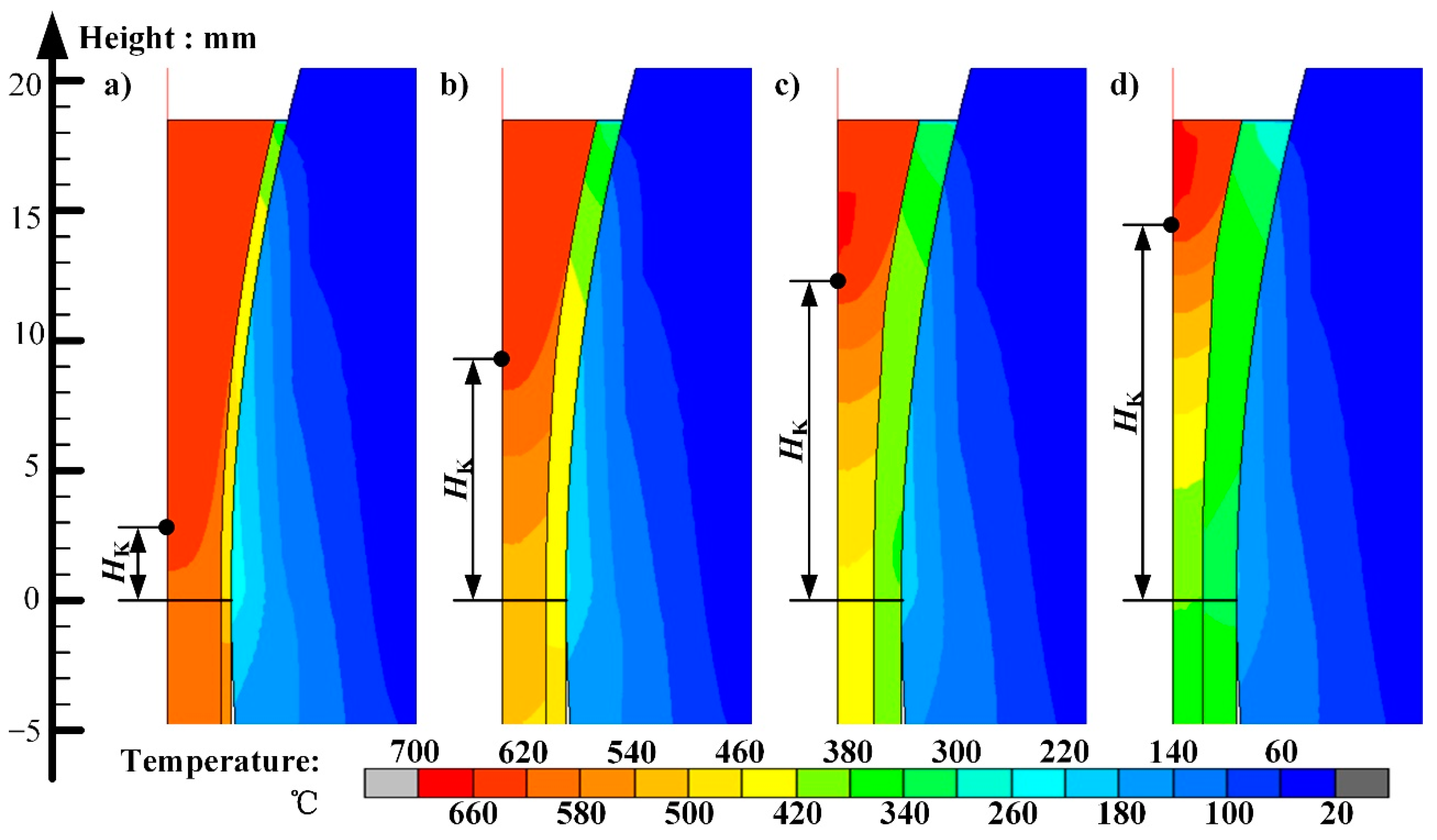
When the thickness of the cladding is different, the simulation results of the temperature distribution in the cast-rolling zone are shown in Figure 5. It can be seen that since the core molten pool does not directly contact the casting roll and can only transfer heat through the clad aluminum alloy strip, the cladding has a significant temperature rise during the cast-rolling process. With an increase in the cladding thickness, the flow rate of the core aluminum melt decreases and the heat energy entering the cast-rolling zone per unit time decreases. At the same time, due to an increase in the cladding thickness, the heat capacity of the cladding increases and the temperature rise of the cladding decreases. At the same time, because of the better heat transfer ability between the cladding and the core melt, the core material is easier to cool and solidify, so the height of the KISS point, which is the boundary point between the solidification stage and the deformation stage of the cast-rolling zone, gradually increases. When the cladding thickness was increased from 0.5 mm to 2 mm, the KISS point height, HK, increased from 2.5 mm to 14.3 mm.
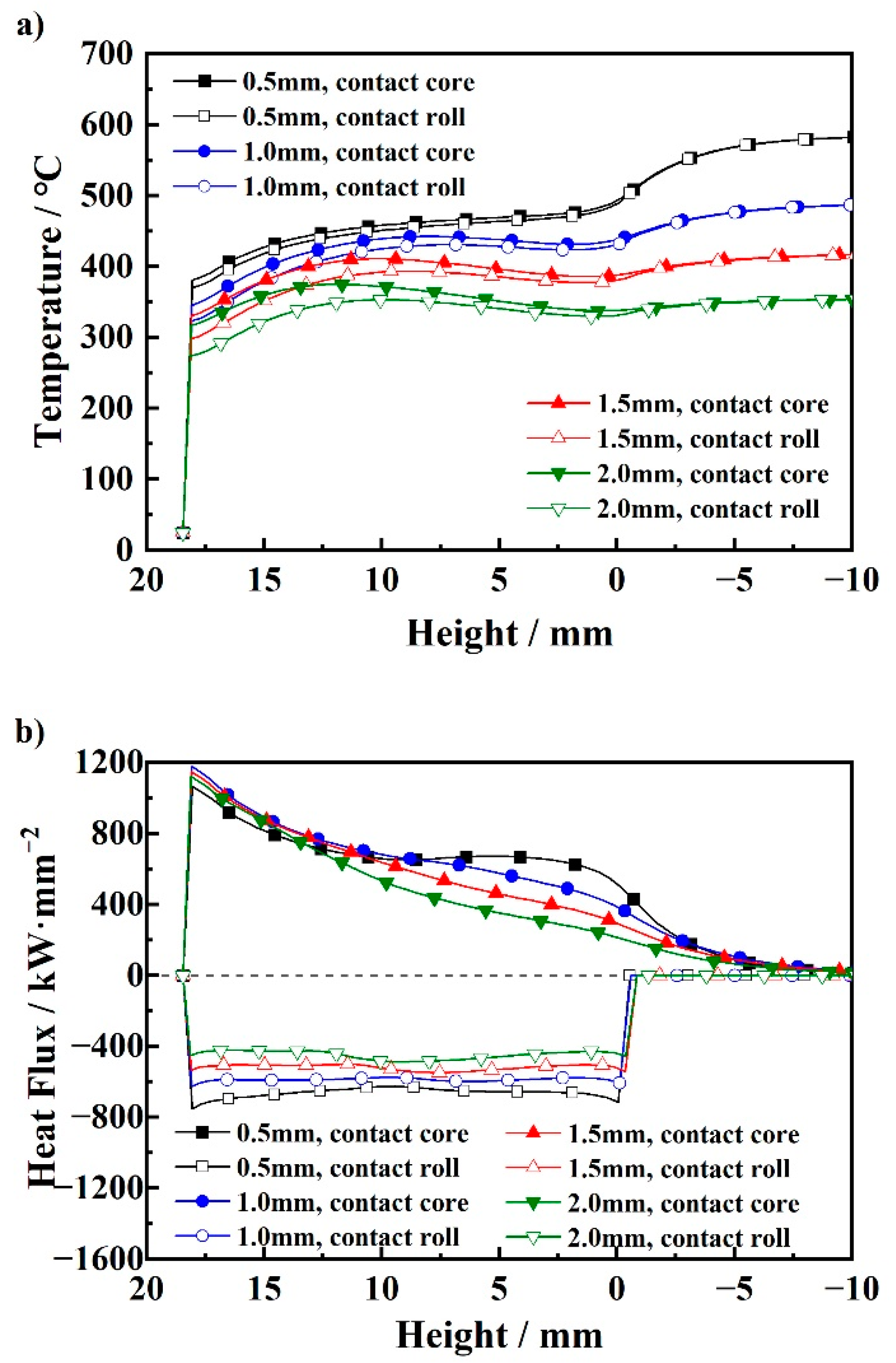
The temperature curves and the heat flux of the cladding are shown in Figure 6. It can be seen that when the thickness of the cladding is 1.0 mm, 1.5 mm, and 2.0 mm, the surface temperature of the cladding first increases, then decreases, and finally increases again to the highest point and then decreases. This is because after the cladding is in contact with the core, the incoming heat flux on the side close to the core is significantly larger than the outgoing heat flux on the side close to the roll. As the temperature of the core decreases, the incoming heat flux gradually decreases. When the incoming and outgoing heat fluxes reach equilibrium, the cladding temperature reaches a maximal value and then begins to decrease. When the three-laminated aluminum composite plate leaves the cast-rolling zone, the heat flux from the cladding to the environment decreases, which is less than the heat flux from the core, and the temperature rises again. Finally, when the heat fluxes re-equilibrate, the temperature of the cladding reaches the maximum value and then begins to cool down. However, when the thickness of the cladding is 0.5 mm, the temperature of the cladding continues to rise. This is because, in the cast-rolling zone, the incoming heat flux on the side close to the core is always greater than the outgoing heat flux on the side close to the roll side, and there is no temperature drop process, but its temperature rise rate decreases due to the slower release process of the latent heat of the solidification of the core. By comparing the temperature curves of the cladding under different cladding thicknesses, it can be seen that with an increase in the cladding thickness, the heat flux received and released by both sides of the cladding decreases. The heat of the molten pool decreases, and the heat capacity of the cladding increases, which reduces the temperature rise of the cladding. The outlet temperature of the cast-rolling zone decreases with an increase in the cladding thickness. When the cladding thickness increases from 0.5 mm to 2 mm, the outlet temperature decreases from 581 °C to 353 °C.
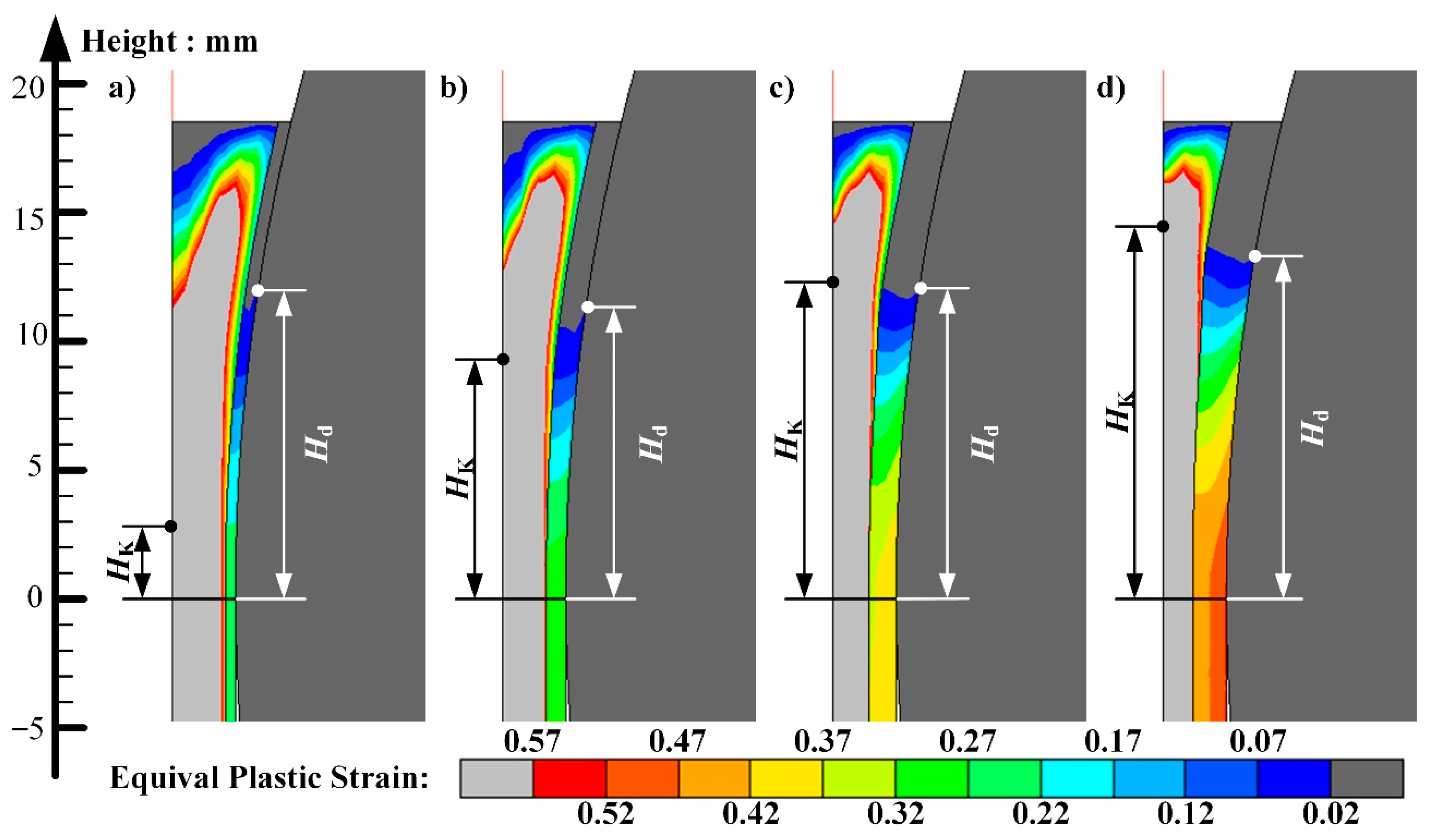
When the cladding thickness is different, the simulation results of deformation in the cast-rolling zone are shown in Figure 7. It can be seen that, at the beginning of cast-rolling, the core is deformed first. This is because the core is in a liquid state at this time, and its deformation is mainly manifested by the flow. Compared with the plastic deformation of the solid, the required deformation force is smaller. The core then solidifies, the deformation resistance increases sharply, and, after the cladding is heated, the deformation resistance decreases. When the two resistances are equal, the cladding begins to deform. At this time, it is considered that the cast-rolling process enters the coordinated deformation stage, and the height of the current position is Hd. By comparing the deformation results of different cladding thicknesses, it can be seen that with an increase in the cladding thickness, the coordinated deformation position height, Hd, first decreases and then increases, and its relative KISS point height, HK, gradually decreases. The coordinated deformation position depends on the temperature of the core and the cladding. With an increase in the cladding thickness, the core temperature cooling rate increases, the solidification rate increases, the KISS point height increases, and the deformation resistance increases, while the cladding temperature rise rate decreases, the temperature rise decreases, and the deformation resistance increases. By comparison, since the core is initially liquid and the temperature is always higher than that of the cladding, the increase in its deformation resistance is much smaller than that of the cladding. The core needs to be completely solidified or cooled to below the solidus temperature in order to have sufficient deformation resistance and coordinate deformation with the cladding. Therefore, the coordinated deformation position, Hd, gradually decreases relative to the KISS point height, HK. When the cladding thickness is 0.5 mm and 1.0 mm, Hd is higher than HK, while when the cladding thickness is 1.5 mm and 2.0 mm, Hd is lower than HK. Since the KISS point height increases with an increase in the cladding thickness, the starting position, Hd, of the coordinated deformation stage first decreases and then increases with an increase in the cladding thickness.
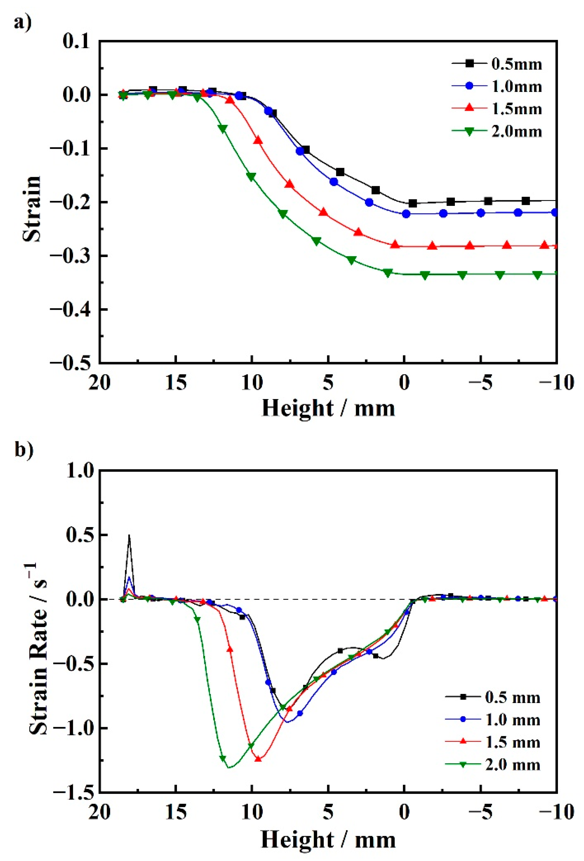
In order to facilitate the comparison of the deformation of the cladding under the conditions of different cladding thicknesses, the strain is used as the comparison variable. The strain curves and strain rate curves are shown in Figure 8. It can be seen from the strain curve that with an increase in the cladding thickness the strain gradually increases, and the position where the strain occurs is gradually closer to the inlet. This is because the coordinated deformation stage gradually becomes longer with an increase in the cladding thickness, and the overall deformation increases, which makes the deformation of each metal component increase. It is worth noting that when the thickness of the cladding is 0.5 mm, the starting position of the coordinated deformation stage is close to that of the case when the thickness of the cladding is 1.0 mm, but the strain is smaller than that of the latter. This is due to the lower core temperature of the latter, and under the conditions of the same overall coordinated deformation the deformation degree of the core is relatively smaller, while the deformation degree and strain of the cladding are relatively larger. From the strain rate curve, it can be seen that at the inlet of the cast-rolling zone the cladding has thermal expansion. Since the temperature rise rate is faster when the cladding thickness is 0.5 mm, the strain rate caused by its expansion is larger. It can be seen from the comparison that with an increase in the cladding thickness, the maximum strain rate of the cladding increases gradually. This is caused by an increase in the starting position of the coordinated deformation stage. According to the geometric structure of the cast-rolling zone, the overall deformation rate increases, which makes the deformation rate of the component metals increase. It is worth noting that when the cladding thickness is 0.5 mm, the strain rate increases again near the outlet of the cast-rolling zone. This is because the KISS point is near the outlet, the core is completely solidified, the deformation resistance increases sharply, and the deformation rate decreases, such that the deformation rate of the cladding increases again. It can be seen from the above analysis that the deformation degree of the cladding is closely related to the temperatures of the cladding and the core, as well as the length of the coordinated deformation stage. In order to realize the precise control of the thickness fraction of the SLS-TRC process, it is necessary to comprehensively control the temperature field in the cast-rolling zone in combination with the rheological properties of the metal components.

3.3. Solid–Liquid-Solid Cast-Rolling Composite Experiment and Composite Interface Bonding Process

In the SLS-TRC process, when the casting roll is stopped urgently and the molten pool is cooled quickly, the cast-rolling zone sample can be obtained. The cast-rolling zone sample was polished until the surface was bright and there was no obvious scratch. The evolution process of the composite interface was observed under a scanning electron microscope.
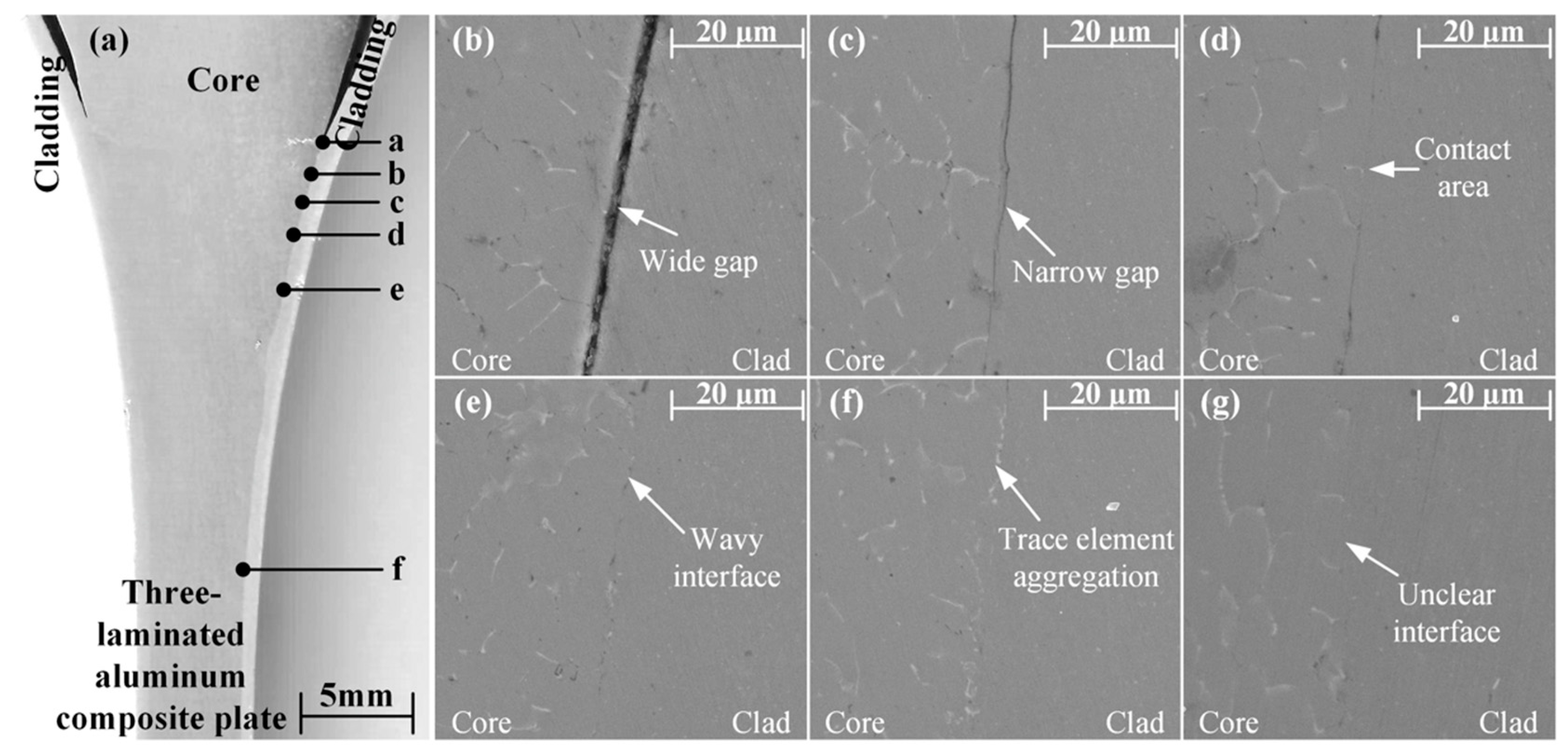
Macroscopically, the composite interface is smooth and flat without gaps, and the cladding thickness has obvious thinning as shown in Figure 9a. The evolution process of the composite interface in SLS-TRC, which could be inferred from the morphology scanning results, can be divided into the following stages: After the core melt enters the cast-rolling zone, the surface cools and shrinks rapidly, and there is a wide gap with the cladding, as shown in the Figure 9b. Thereafter, under the action of rolling force, the core and cladding are compressed together, and the previous gap is narrowed, as shown in the Figure 9c. Under the further action of rolling force, the gap disappears, and the core begins to contact the cladding directly, as shown in the Figure 9d. A large amount of heat is transferred from the core to the cladding, and the cladding surface begins to fuse locally, where it is in close contact with the core, and the composite interface is no longer flat and wavy, as shown in the Figure 9e. With the rolling process, the gap between the cladding and the core completely disappears, the components are completely in contact, and the trace elements in the core accumulate at the composite interface, as shown in the Figure 9f. Due to the high temperature in the cast-rolling zone, the core structure recrystallizes in the subsequent process, and the trace elements accumulated at the interface redissolve into the aluminum alloy grains. The composite interface between the core and the cladding is unclear and difficult to observe, and the two components form a firm bond, as shown in the Figure 9g.
The above bonding process follows the N. Bay metal bonding theory, which points out that in the process of metal recombination, metal deformation is required to rupture the surface oxide film and the work-hardened layer, and the activated metal is formed into a bond via pressure [25]. Therefore, for the SLS-TRC process, it can be judged whether the interior of the three-laminated aluminum composite plate manufactured is bonded by whether the cladding aluminum strip is deformed.

4. LSL-TRC Process

4.1. Thermal Mechanical Coupling Calculation Model of the LSL-TRC Process

In order to explore the effect of core thickness on the coordinated deformation of three-laminated aluminum composite plates in the process of LSL-TRC, 2D thermomechanical coupling models of LSL-TRC were established by using the same method as that of SLS-TRC. The process parameters of the LSL-TRC process are shown in Table 5. The 1/2 model is also used for mesh division, and the division result is shown in Figure 10. The calculation area includes one casting roll, one clad aluminum molten pool, and a 1/2 core aluminum plate.
The boundary condition setting of the thermal mechanical coupling model of a 1060/3003/1060 three-laminated aluminum composite plate’s LSL-TRC process is consistent with that of the SLS-TRC process. The difference is that the clad aluminum liquid contacts the casting roll and core aluminum plate at the same time, and the heat transfer coefficient can still be calculated according to Formula (5).

4.2. Simulation Results

When the thickness of the core is different, the simulation results of the temperature distribution in the cast-rolling zone are shown in Figure 11. It can be seen that the cladding aluminum melt is in direct contact with the core aluminum plate and the casting roll sleeve, but due to the different cooling capacities on both sides of the molten pool, the KISS point is biased towards the core material side with a weaker cooling capacity. In the process of cast-rolling, the core can only receive the heat from the cladding through its own heat capacity, and cannot be exported. When the temperature of the core is higher than that of the cladding, the heat flux changes direction and transfers from the core to the cladding, and is then exported through the casting roll. Therefore, in the LSL-TRC the heat transfer process at the composite interface is bidirectional. Through the process comparison, it can be seen that as the thickness of the core increases, the flow rate of the cladding aluminum melt decreases, the heat energy entering the cast-rolling zone per unit time decreases, the height of the KISS point increases, and the thickness of the core material increases from 1.0 mm to 4.0 mm; the KISS point height increased from 8.98 mm to 18.42 mm. At the same time, due to the increase in the thickness of the core, the heat capacity increases, the temperature rise of the core decreases, and the outlet temperature of the cast-rolling zone decreases gradually.
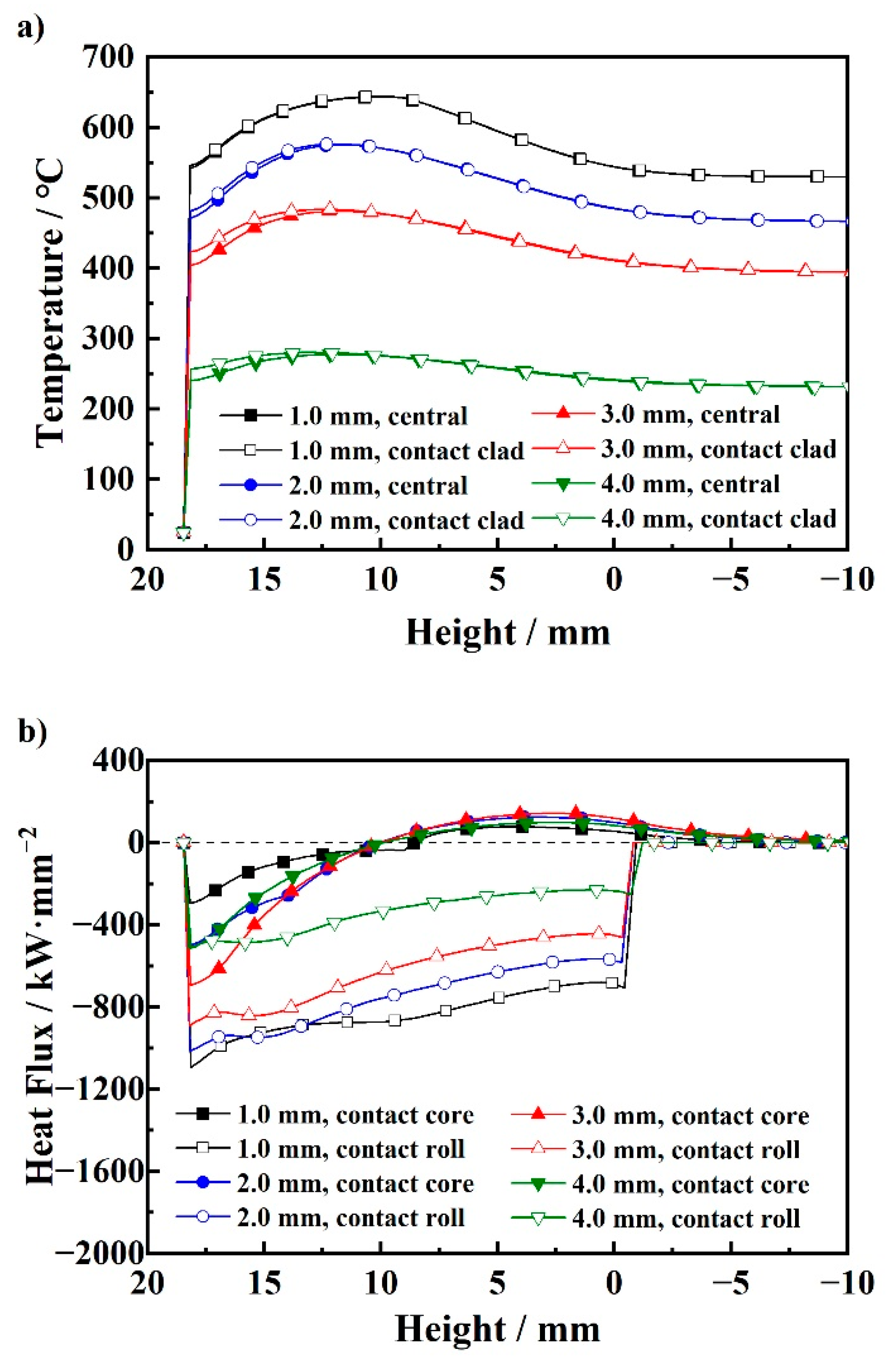
Figure 12 shows the temperature curves of the core surface and the symmetry plane, as well as the heat flux curves on both sides of the cladding. It can be seen that the temperatures of the core surface and the core symmetry plane both increase first and then decrease. The surface of the core has a higher temperature than the highest point of the symmetry temperature, and the position of the core surface highest temperature is also higher. This is due to the hysteresis of heat flow reversal and the temperature. Through the comparison of different core thicknesses, it can be determined that as the thickness of the core increases, the maximum value of the core temperature gradually decreases, and the temperature at the outlet of the cast-rolling zone gradually decreases. When the thickness of the core increases from 1.0 mm to 4.0 mm, the outlet temperature decreased from 544 °C to 240 °C. From the heat flux curves on both sides of the cladding, it can be seen that the direction of the heat flow at the composite interface is reversed, while the heat flux at the interface with the casting roll sleeve only maintains one direction. By comparison, it is found that with an increase in the thickness of the core, the initial heat flux at the composite interface increases first and then decreases, and the heat flux also increases first and then decreases after changing the heat flux direction. This is due to an increase in the thickness of the core; its own heat capacity increases, the temperature is lower, and the heat flow increases. However, when the core thickness increases, the mass of the cladding decreases and the heat of the cladding decreases, so the heat flux tends to decrease subsequently. The heat flux at the interface with the casting roll sleeve decreases gradually with an increase in the thickness of the core, which is related to a reduction in the heat contained in the cladding. It is worth noting that the heat flux to the casting roll sleeve decreases gradually during the cast-rolling process due to the decrease in the temperature of the cladding.
When the core thickness is different, the simulation results of deformation in the cast-rolling zone are shown in Figure 13. It can be seen that at the beginning of cast-rolling the cladding first deforms and then the temperature of the core increases sharply, the deformation resistance decreases rapidly, deformation occurs, and the coordinated deformation stage is entered. By comparison, it can be determined that with an increase in the thickness of the core, the starting position of the coordinated deformation, Hd, relative to the height of the KISS point, HK, gradually decreases. It can be seen from the above analysis that the starting position of coordinated deformation is mainly related to the decrease in the core deformation resistance caused by the increase in the temperature and the increase in the cladding deformation resistance caused by the solidification. As the thickness of the core increases, the temperature of the core decreases significantly, the deformation resistance increases, and the heat contained in the cladding decreases, making it easier to solidify, but the increase is much smaller than that of the core material. Therefore, the coordinated deformation position, Hd, gradually decreases relative to the KISS point height, HK. When the thickness of the core is 1.0 mm, 2.0 mm and 3.0 mm, the coordinated deformation position is above the KISS point. While the thickness of the core is 4.0 mm, the coordinated deformation position is below the KISS point. Therefore, with an increase in the thickness of the core material, the starting position of the coordinated deformation stage, Hd, first remains unchanged and then decreases.
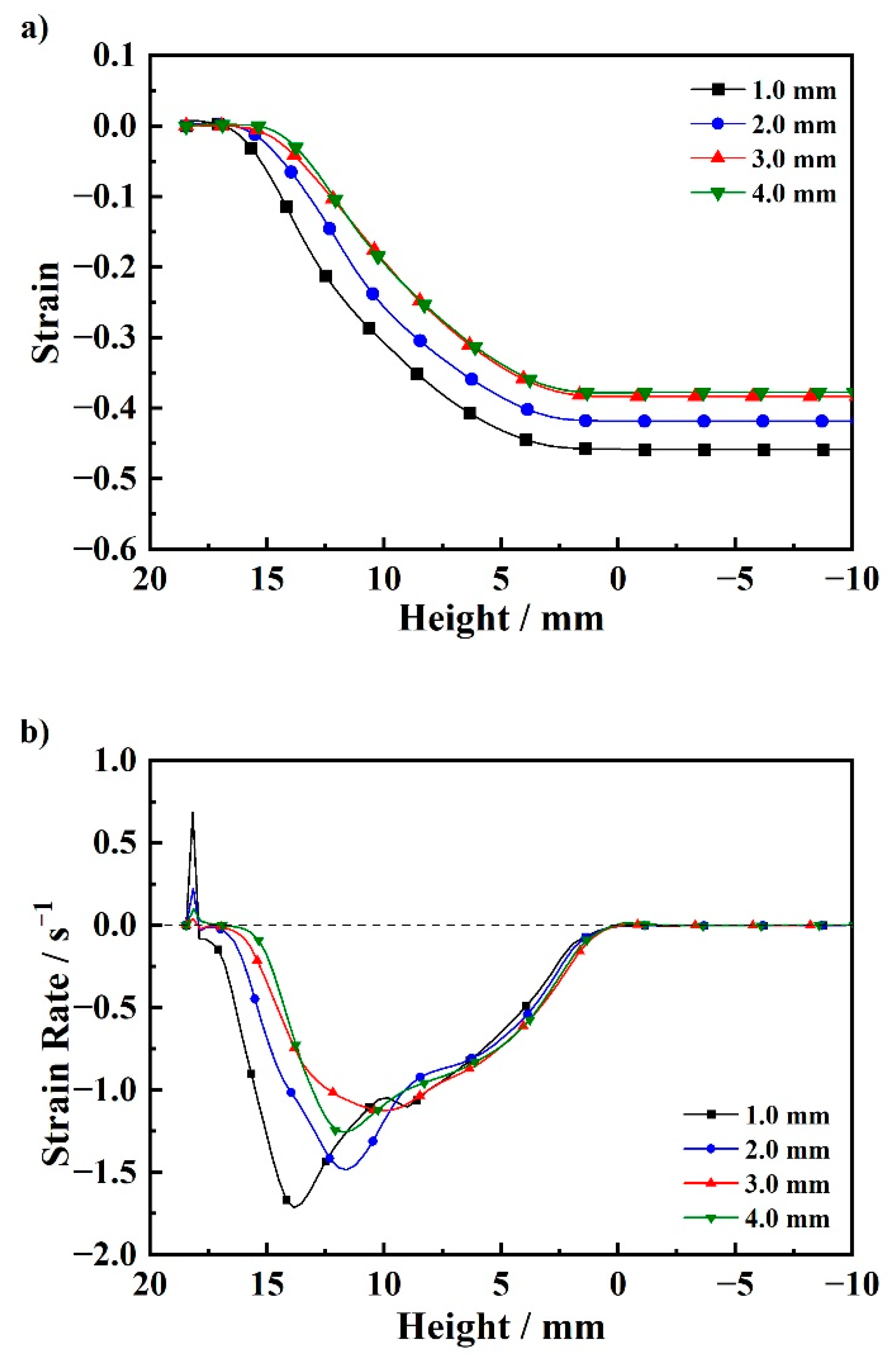
The core strain curves and the strain rate curves are shown in Figure 14. It can be seen from the strain curve that as the thickness of the core increases, the strain gradually decreases. When the thickness of the core is 3.0 mm and 4.0 mm, the strain is basically the same. This is because the coordinated deformation stage of the latter is shorter and the overall deformation is lower, but the temperature of the cladding is lower, and, at the same time, the deformation degree of the cladding increases, which makes the deformation resistance greater. In the process of coordinated deformation, the latter core deformation is larger. It can be seen from the strain rate curves that as the thickness of the core increases, the maximum strain rate of the core gradually decreases, and the position of the maximum strain rate gradually approaches the outlet. It is worth noting that when the thickness of the core is 4.0 mm the deformation of the core material increases due to the sharp increase in the deformation resistance of the cladding, and the strain rate increases. The above analysis shows that the degree of core deformation is closely related to the temperatures of the core and the cladding, as well as the degree of the cladding deformation. In particular, when the degree of cladding deformation is larger, its deformation resistance increases sharply, forcing the core to experience more substantial deformation. Therefore, in order to realize the precise control of the layer thickness fraction of the LSL-TRC process, the deformation characteristics of the liquid metal components also need to be considered.

4.3. LSL-TRC Experiment and Composite Interface Bonding Process

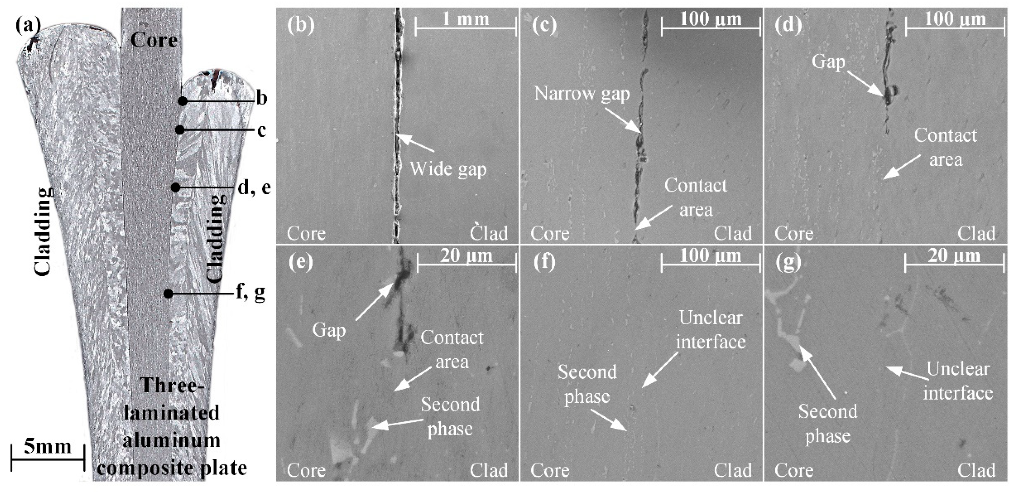
The manufacturing process of the LSL-TRC cast-rolling zone sample, shown in Figure 15, is the same as that of SLS-TRC. Macroscopically, the composite interface is smooth and flat without gaps, and the core thickness has obvious thinning as shown in Figure 15a. The morphology scanning results can infer the evolution process of composite interfaces in LSL-TRC. After the cladding melt enters the cast-rolling zone, the surface cools and shrinks rapidly, and there is a wide gap between the cladding and the core, as shown in Figure 15b. Then, under the action of rolling force, the core and cladding are compressed together and begin to contact directly; the gap is narrowed at the same time, as shown in Figure 15c. With the rolling process, the contact area between the core and the cladding increases gradually, as shown in Figure 15d. By increasing the magnification of the viewing area, it can be seen that a large number of second phases in the core are located at the composite interface as shown in Figure 15e. Finally, under the action of rolling force, the core is in full contact with the cladding, and the interface cannot be easily observed in a low-magnification field of vision. The core and the cladding can only be distinguished by a large number of second-phase characteristics in the core, as shown in Figure 15f. After magnification, it can be seen that the interface between the cladding and core is smooth and flat, as shown in Figure 15g, and the bonding effect is substantial.
The above bonding process is consistent with the SLS-TRC process, and follows the N. Bay metal bonding theory. Therefore, for the LSL-TRC process of three-laminated aluminum composite plates, it can be judged whether the interior manufactured by the core aluminum plate is deformed or not.

5. Comparison of the SLS-TRC Process and LSL-TRC Process

In order to visually express the difference between the SLS-TRC process and the LSL-TRC process, conditions with the same thickness of solid components are taken for a comparative analysis. In the SLS-TRC process, a cladding thickness of 1.0 mm is selected, compared with a core thickness of 2.0 mm in the LSL-TRC process.
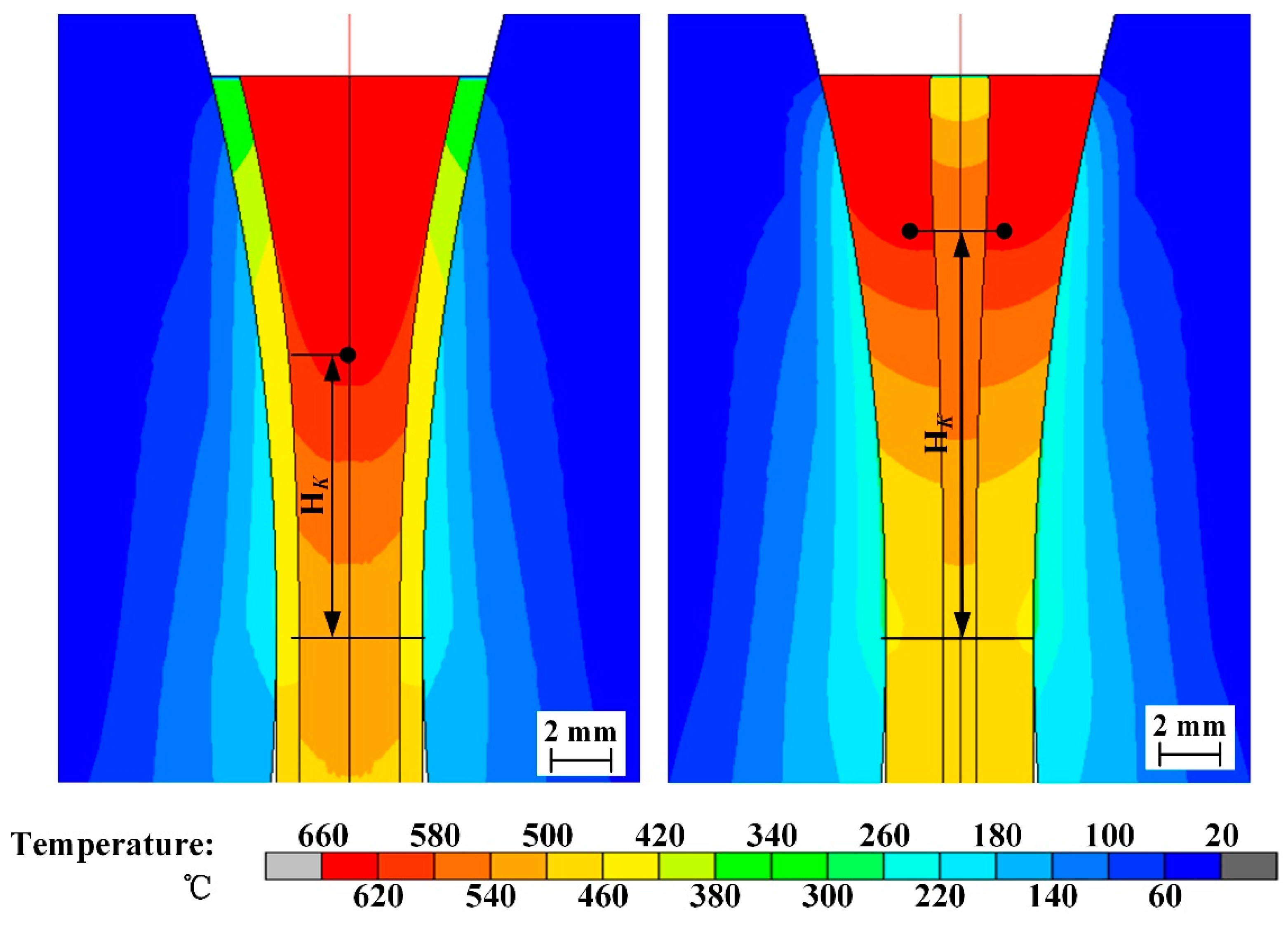
The temperature distribution comparison of the two processes is shown in Figure 16. It can be seen that, due to the difference in the heat transfer conditions, the SLS-TRC process in which the aluminum melt cannot be in direct contact with the casting roll is compared with the LSL-TRC process; the former has a lower casting roll temperature and slower molten pool cooling. The solidification process is longer and the KISS point height is lower. During cast-rolling, the casting speed needs to be kept relatively slow to avoid the risk of leakage. However, in the process of LSL-TRC, the core aluminum plate cannot directly transfer heat to the outside, and can only rely on its own heat capacity to absorb heat. In this process, the core aluminum plate is easily melted. In order to prevent the core aluminum plate from being melted, the casting temperature should be reduced as much as possible, and the thickness of the core aluminum plate should be increased.
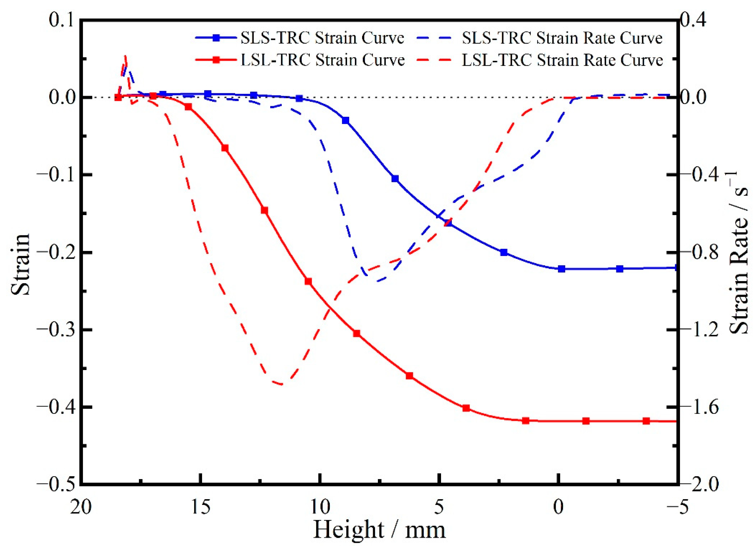
The strain curves and strain rate curves of the solid component in the two processes are shown in Figure 17. It can be seen that at the inlet of the cast-rolling zone the solid components are thermally expanded, and the LSL-TRC process expands slightly more than the SLS-TRC process. Since the core temperature of LSL-TRC is significantly higher than the cladding temperature of SLS-TRC in the cast-rolling zone, the deformation position of the former core is significantly higher than that of the latter cladding. According to the geometric characteristics of the cast-rolling zone, its deformation speed and total deformation are also significantly higher than the latter. However, the deformation characteristics of the solid component in the two processes remain the same, and the overall deformation speed first increases and then decreases. The strain rate curve is S-shaped.
The solid components have thickness reduction during the two processes. During the cast-rolling process the thickness fraction of SLS-TRC gradually decreased, while that of LSL-TRC gradually increased. Therefore, when manufacturing a three-laminated aluminum composite plate that requires an accurate thickness fraction, it is necessary to select an appropriate cast-rolling process and initial solid component thickness according to the target thickness fraction.
Through the analysis of the combination process of the SLS-TRC experiment and the LSL-TRC experiment, it is determined that the composite mechanism of the two processes is the N. Bay theory. Therefore, in order to make the combination of the core and the cladding firmer in the process of manufacturing, deformation is essential. However, in the context of the energy crisis, in order to achieve a greener, lower cost manufacturing process, it is necessary to consider the energy consumed by these two processes.
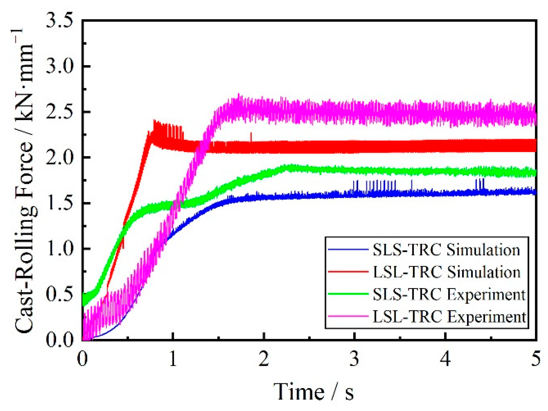
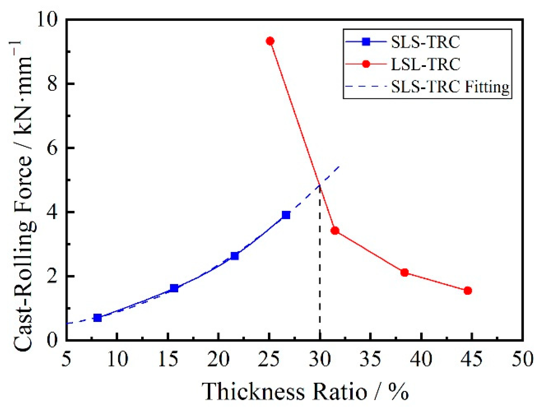
In the manufacturing process, the energy consumed is mainly used to drive the rotation of the casting roll to provide cast-rolling force to the cast-rolling zone. The cast-rolling force curves of the two processes obtained from simulations and experiments are shown in Figure 18. It can be seen that under the conditions of the same thickness of solid metal components, due to the faster cooling of the liquid cladding in the LSL-TRC process, the deformation resistance is greater. The required cast-rolling force is greater. Figure 19 shows the thickness fraction at the outlet and the cast-rolling force under the conditions of different solid-phase metal thicknesses. It can be seen that when manufacturing a three-laminated aluminum composite plate with a relatively small thickness fraction (the thickness fraction is less than 30%), the SLS-TRC process requires less load. When manufacturing a three-laminated aluminum composite plate with a relatively large thickness fraction (the thickness fraction is greater than 30%), LSL-TRC requires less load.

6. Conclusions

(1)
In the solid–liquid–solid twin-roll casting (SLS-TRC) composite process of three-laminated aluminum composite plates, the core molten pool does not directly contact the casting roll, the heat energy is transferred through the cladding, and the heat energy transfer efficiency to the casting roll is low. As the thickness of the cladding increases, the flow rate of the core aluminum melt decreases, the heat decreases, the height of the KISS point increases, the temperature rise of the cladding decreases, the starting position of the coordinated deformation gradually decreases relative to the height of the KISS point, the deformation degree of the cladding increases, and the deformation rate increases. The interface bonding process follows the N. Bay theory, and there is large deformation during the cast-rolling process.
(2)
In the liquid–solid–liquid twin-roll casting (LSL-TRC) composite process of three-laminated aluminum composite plates, the cladding molten pool can directly contact the casting roll, and the heat energy transfer efficiency to the casting roll is high. The heat in the core is released to the cladding as the cladding temperature decreases. As the thickness of the core material increases, the molten cladding aluminum flow rate at the inlet decreases, the heat decreases, the height of the KISS point increases, the temperature rise of the core decreases, the starting position of the coordinated deformation gradually decreases relative to the height of the KISS point, the deformation degree of the cladding increases, and the deformation rate increases. The interface bonding process conforms to the N. Bay theory, and there is also large deformation during the cast-rolling process.
(3)
Through the comparison of the two processes, it can be seen that the KISS point height of the SLS-TRC process is lower and that there is a risk of melt leakage, while the core temperature of the LSL-TRC process is higher and there is a risk of the core being melted. Through the comparison of different solid component thicknesses and the cast-rolling forces required by the two processes, it is determined that when manufacturing a three-laminated aluminum composite plate with a relatively small thickness fraction (the thickness fraction is less than 30%), the SLS-TRC process requires less load. When manufacturing a three-laminated aluminum composite plate with a relatively large thickness fraction (the thickness fraction is greater than 30%), LSL-TRC requires less load.

Author Contributions

H.H. conceived the research and discussed the results. R.Z. established the simulation model and wrote the manuscript. M.Y. performed the experiments and analyzed the data. Z.J. and D.G. conducted preliminary investigation and collected the data. All authors have read and agreed to the published version of the manuscript.

Funding

This research was funded by the National Key Research and Development Project of China (2018YFA0707300), National Natural Science Foundation of China (51974278), National Natural Science Foundation of China Youth Fund (52204406); Natural Science Foundation of Hebei Province Distinguished Young Fund Project (E2018203446), the Natural Science Foundation of Hebei Province Young Fund Project (E2020203118), and the Hebei Province High Level Talent Fund Project (B2020003013). And The APC was funded by the National Key Research and Development Project of China (2018YFA0707300).

Conflicts of Interest

The authors declare no conflict of interest.

References

  1. Zhang, H.-T.; Han, X.; Wang, D.-T.; Shao, B.; Qin, K.; Cui, J.-Z. Effect of clad ratio on interfacial microstructure and properties of cladding billets via direct-chill casting process. Trans. Nonferrous Met. Soc. China 2018, 28, 998–1006. [Google Scholar] [CrossRef]
  2. Honarpisheh, M.; Asemabadi, M.; Sedighi, M. Investigation of annealing treatment on the interfacial properties of explosive-welded Al/Cu/Al multilayer. Mater. Des. 2012, 37, 122–127. [Google Scholar] [CrossRef]
  3. Yan, G.Y.; Feng, M.A.; Cao, Z.Q.; Li, T.J.; Wang, T.M. Deformation and heat treatment ability of three-layer 6009/7050/6009 Al alloy clad slab prepared by direct-chill casting. Trans. Nonferrous Met. Soc. China 2018, 28, 9–19. [Google Scholar] [CrossRef]
  4. Lee, K.S.; Lee, Y.S.; Kwon, Y.N. Influence of secondary warm rolling on the interface microstructure and mechanical properties of a roll-bonded three-ply Al/Mg/Al sheet. Mater. Sci. Eng. A 2014, 606, 205–213. [Google Scholar] [CrossRef]
  5. Zhang, X.P.; Yang, T.H.; Castagne, S.; Wang, J.T. Microstructure; bonding strength and thickness ratio of Al/Mg/Al alloy laminated composites prepared by hot rolling. Mater. Sci. Eng. A 2011, 528, 1954–1960. [Google Scholar] [CrossRef]
  6. Gao, H.T.; Liu, X.H.; Qi, J.L.; Ai, Z.R.; Liu, L.Z. Microstructure and mechanical properties of Cu/Al/Cu clad strip processed by the powder-in-tube method. J. Mater. Processing Technol. 2018, 251, 1–11. [Google Scholar] [CrossRef]
  7. Mao, Z.; Xie, J.; Wang, A.; Wang, W.; Ma, D. Interfacial characterization and bonding properties of copper/aluminum clad sheets processed by horizontal twin-roll casting, multi-pass rolling, and annealing. Metals 2018, 8, 645. [Google Scholar] [CrossRef] [Green Version]
  8. Grydin, O.; Stolbchenko, M.; Schaper, M.; Belejová, S.; Králík, R.; Bajtošová, L.; Křivská, B.; Hájek, M.; Cieslar, M. New twin-roll cast Al-Li based alloys for high-strength applications. Metals 2020, 10, 987. [Google Scholar] [CrossRef]
  9. Xu, Z.; Wang, S.; Wang, H.; Song, H.; Li, S.; Chen, X. Effect of cooling rate on Microstructure and properties of twin-roll casting 6061 aluminum alloy sheet. Metals 2020, 10, 1168. [Google Scholar] [CrossRef]
  10. Haga, T. High speed roll caster for aluminum alloy. Metals 2021, 11, 520. [Google Scholar] [CrossRef]
  11. Bae, J.H.; Rao, A.P.; Kim, K.H.; Kim, N.J. Cladding of Mg Alloy with Al by Twin-Roll Casting. Scr. Mater. 2011, 64, 836–839. [Google Scholar] [CrossRef]
  12. Park, J.; Song, H.; Kim, J.-S.; Sohn, S.S.; Lee, S. Three-Ply Al/Mg/Al Clad Sheets Fabricated by Twin-Roll Casting and Post-Treatments (Homogenization Warm Rolling, and Annealing). Metall. Mater. Trans. A 2017, 48, 57–62. [Google Scholar] [CrossRef]
  13. Xu, J.; Fu, J.; Li, S.; Xu, G.; Li, Y.; Wang, Z. Effect of Annealing and Cold Rolling on Interface Microstructure and Properties of Ti/Al/Cu Clad Sheet Fabricated by Horizontal Twin-Roll Casting. J. Mater. Res. Technol. 2022, 16, 530–543. [Google Scholar] [CrossRef]
  14. Zhao, R.; Huang, H.; Yan, M.; Shen, H.; Yang, J. Effect of Cast Roll Sleeve Material on Temperature Field of Sandwich Composite Plate Solid-Liquid-Solid Twin-Roll Casting Process. Metall. Mater. Trans. B 2022, 53, 2051–2065. [Google Scholar] [CrossRef]
  15. Ji, C.; Huang, H.; Zhang, X.; Zhao, R. Numerical and experimental research on fluid flow, solidification, and bonding strength during the twin-roll casting of Cu/Invar/Cu clad strips. Metall. Mater. Trans. B 2020, 51, 1617–1631. [Google Scholar] [CrossRef]
  16. Huang, H.; Liu, W.; Wang, W. Thermal-Mechanical Coupled Modelling and Numerical Simulation for Twin-Roller Casting Process with Technique of Deactivate and Reactivate Element. China Mech. Eng. 2015, 26, 1503–1508. [Google Scholar]
  17. Ji, C.; Huang, H.; Zhang, J.; Zhao, R. Influence of the Substrate Strip on the Asymmetric Heat Transfer of Twin-Roll Casting for Fabricating Bimetallic Clad Strips. Appl. Therm. Eng. 2019, 158, 113818. [Google Scholar] [CrossRef]
  18. Zhan, L. Rheological Behavior Research and Thermo-Mechanical Coupled Analysis of Aluminium Continuous Roll Casting Process. Ph.D. Thesis, Central South University, Changsha, China, 2005. [Google Scholar]
  19. Park, J.J. Numerical analyses of cladding processes by twin-roll casting: Mg-AZ31 with aluminum alloys. Int. J. Heat Mass Transf. 2016, 93, 491–499. [Google Scholar] [CrossRef]
  20. Huang, H.; Liu, W.; Ye, L.; Du, F. Mechanism of Interface Local Fusion for Cu /Al Cladding Strip Fabricated in Twin-roll Casting and Bonding Process at Different Temperatures. J. Harbin Eng. Univ. 2016, 37, 432–437. [Google Scholar]
  21. Levykina, A.G.; Shkatov, V.V.; Mazur, I.P. Hot Rolling Strips at the Casting and Rolling Unit During Coil-to-Coil and Endless Rolling Modes. Procedia Manuf. 2019, 37, 472–477. [Google Scholar] [CrossRef]
  22. Mihalow, F.A. Radiation Thermometry in the steel Industry. In Theory and Practice of Radiation Thermometry; DeWitt, D.P., Nutter, G.D., Eds.; John Wiley & Sons: New York, NY, USA, 1998; pp. 861–904. [Google Scholar]
  23. Li, X.; Hu, S.; Xiao, W.; Zhu, Z. Analysis of the contact conductance and temperature distribution of strip in fast roll casting. Heavy Mach. 1999, 3, 34–37. [Google Scholar]
  24. Haugh, M.J. Radiation Thermometry in the aluminum Industry. In Theory and Practice of Radiation Thermometry; DeWitt, D.P., Nutter, G.D., Eds.; John Wiley & Sons: New York, NY, USA, 1998; pp. 905–972. [Google Scholar]
  25. Bay, N. Cold welding. Part 1: Characteristics, bonding mechanisms, bond strength. Met. Constr. 1986, 18, 369–401. [Google Scholar]
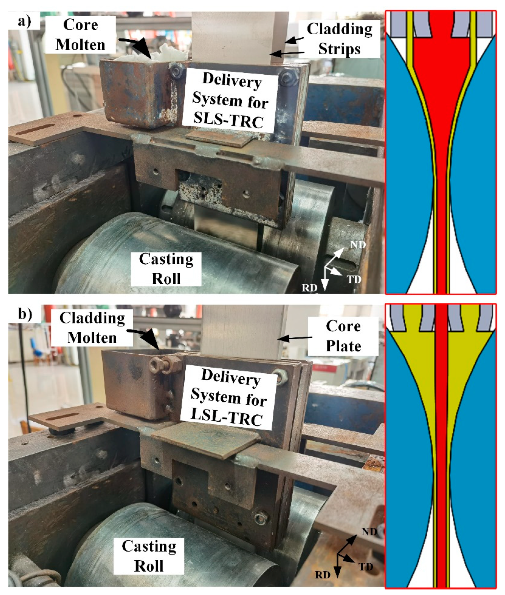
Figure 1. Schematic diagram of SLS-TRC and LSL-TRC process of three-laminated aluminum composite plate. (a) SLS-TRC; (b) LSL-TRC.
Metals 12 01710 g001
Figure 2. Flow stress of Al3003 aluminum alloy.
Metals 12 01710 g002
Figure 3. Mesh model of SLS-TRC for three-laminated aluminum composite plate.
Metals 12 01710 g003
Figure 4. Schematic diagram of activate elements and deactivate elements.
Metals 12 01710 g004
Figure 5. Contour bands of SLS-TRC temperature distribution with different clad thickness. (a) H1060 = 0.5 mm; (b) H1060 = 1.0 mm; (c) H1060 = 1.5 mm; (d) H1060 = 2.0 mm.
Metals 12 01710 g005
Figure 6. Curves of temperature and heat flux of clad of SLS-TRC with different clad thickness. (a) Temperature curves; (b) Heat flux curves.
Metals 12 01710 g006
Figure 7. Contour bands of SLS-TRC strain distribution with different clad thickness. (a) H1060 = 0.5 mm; (b) H1060 = 1.0 mm; (c) H1060 = 1.5 mm; (d) H1060 = 2.0 mm.
Metals 12 01710 g007
Figure 8. Curves of strain and strain rate of clad in SLS-TRC with different clad thickness. (a) Strain curves; (b) Strain rate curves.
Metals 12 01710 g008
Figure 9. Evolution process of interface of SLS-TRC.
Metals 12 01710 g009
Figure 10. Mesh model of LSL-TRC for three-laminated aluminum composite plate.
Metals 12 01710 g010
Figure 11. Contour bands of LSL-TRC temperature distribution with different core thickness. (a) H3003 = 1.0 mm; (b) H3003 = 2.0 mm; (c) H3003 = 3.0 mm; (d) H3003 = 4.0 mm.
Metals 12 01710 g011
Figure 12. Curves of core temperature and clad heat flux of LSL-TRC with different core thickness. (a) Core temperature curves; (b) Clad heat flux.
Metals 12 01710 g012
Figure 13. Contour bands of LSL-TRC strain distribution with different core thickness. (a) H3003 = 1.0 mm; (b) H3003 = 2.0 mm; (c) H3003 = 3.0 mm; (d) H3003 = 4.0 mm.
Metals 12 01710 g013
Figure 14. Curves of strain and strain rate of core in LSL-TRC with different core thickness. (a) Strain curves; (b) Strain rate curves.
Metals 12 01710 g014
Figure 15. Evolution process of interface of LSL-TRC.
Metals 12 01710 g015
Figure 16. Comparison of the temperature distribution of the two processes. (left) SLS-TRC; (right) LSL-TRC.
Metals 12 01710 g016
Figure 17. The strain curves and strain rate curves of the solid component in the two processes.
Metals 12 01710 g017
Figure 18. Cast-rolling force curves obtained from simulations and experiments of the two processes.
Metals 12 01710 g018
Figure 19. Variation law of cast-rolling force with outlet thickness fraction in two processes.
Metals 12 01710 g019
Table 1. Chemical composition of materials. (Mass fraction, %).
MaterialMnFeSiAl
10600.030.350.25Bal.
30031.0~1.50.70.6Bal.
Table 3. Thermophysical properties of casting rolls.
Temperature (°C)Density (g/cm3)Specific Heat (J/(kg·K))Heat Conductivity (W/(m·K))
207.8545.1461
10045.1496
20044.1533
30041.9568
Table 4. Process Parameters of SLS-TRC.
ParametersUnitSelect ValueSelect Range
T1060°C25-
T3003°C660-
Casting speedm/min1.4-
Molten pool heightmm18.5-
H1060mm0.50.5, 1.0, 1.5 and 2.0
outlet thicknessmm5-
T1060Al1060 temperature, T3003Al3003 temperature, v—casting speed, L—length of cast-rolling zone, H1060Al1060 thickness, HOutoutlet thickness of casting-rolling zone.
Table 5. Process Parameters of LSL-TRC.
ParametersUnitSelect ValueSelect Range
T1060°C660-
T3003°C25-
Casting speedm/min1.4-
Molten pool heightmm18.5-
H3003mm1.01.0, 2.0, 3.0 and 4.0
outlet thicknessmm5-
Publisher’s Note: MDPI stays neutral with regard to jurisdictional claims in published maps and institutional affiliations.