2. Experimental Process
In this paper, a 1:4 hydraulic model experiment is carried out. The parameters and experimental condition are listed in
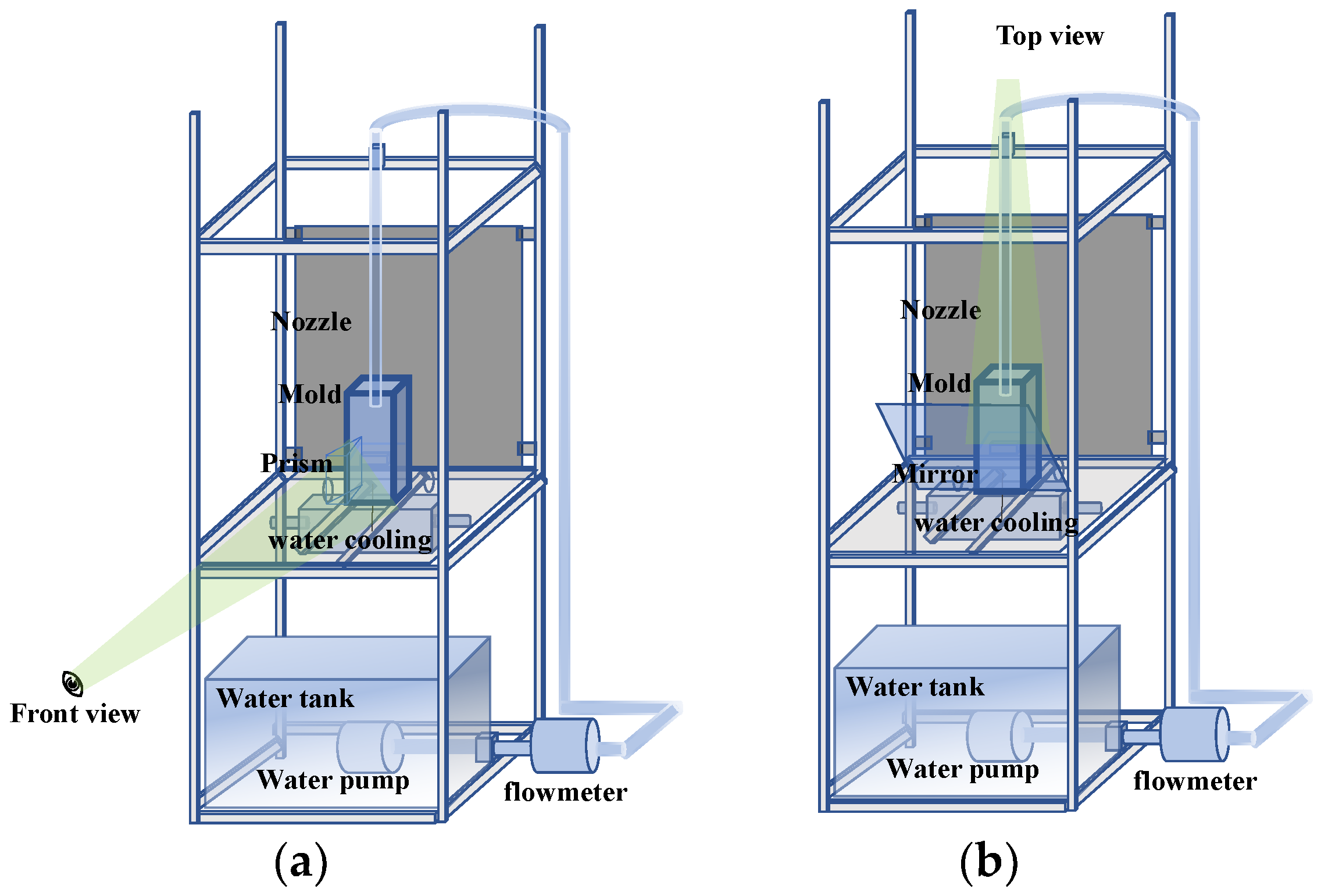
Table 1. PHOTRON WX-50 camera (Tokyo, Japan, shot at 750 frames/s) is used from the two angles (front and top) to take pictures. when it is placed on the front of the mold, triangular prism is placed on the left side of the mold, and the data of the front and side view directions are recorded at the same time (
Figure 1a); when it is placed above the mold, the plane mirror is placed at 45° in front of the mold, and front and the top view data are captured at the same time (
Figure 1b). The obtained quasi-three-dimensional data are helpful to determine the form of the hydraulic jump from different angles, including hydraulic jump heights, the time for the liquid level to stabilize, and the corresponding velocity during cast start, etc.
In order to better analyze the hydraulic jump behavior, three physical forms of the hydraulic jump are set. The first form—after the jet hits the dummy bar surface, circular hydraulic jump starts, and the center of the mold is a cavity with a very thin liquid film here, that is, surface flow. Because the walls of mold exist, after the flow arrives at the wall then is blocked and comes back to the center of the mold, circular hydraulic jump begins to disappear at that moment, which is hereafter called CHJ. The second form—the CHJ disappears and transforms to a common stationary hydraulic jump (hydraulic jump transition begins, which is gradually dominated by gravity), flows back to the center, and fills up the cavity formed by the hydraulic jump. At that moment, CHJ completely disappearing, then a common stationary hydraulic jump begins, which is hereafter called HJT. The third form—after HJT, hydraulic jump is mainly dominated by gravity, the liquid surface rises and the flow pattern gradually stabilizes, which is similar to meniscus during the steady casting, and from a certain moment the state of the flow pattern basically does not change significantly before the nozzle is immersed (although there is difference in flow field between the nozzle’s immersed situation and not-immersed situation), that is, steady liquid level at that moment, hereafter called SLL.
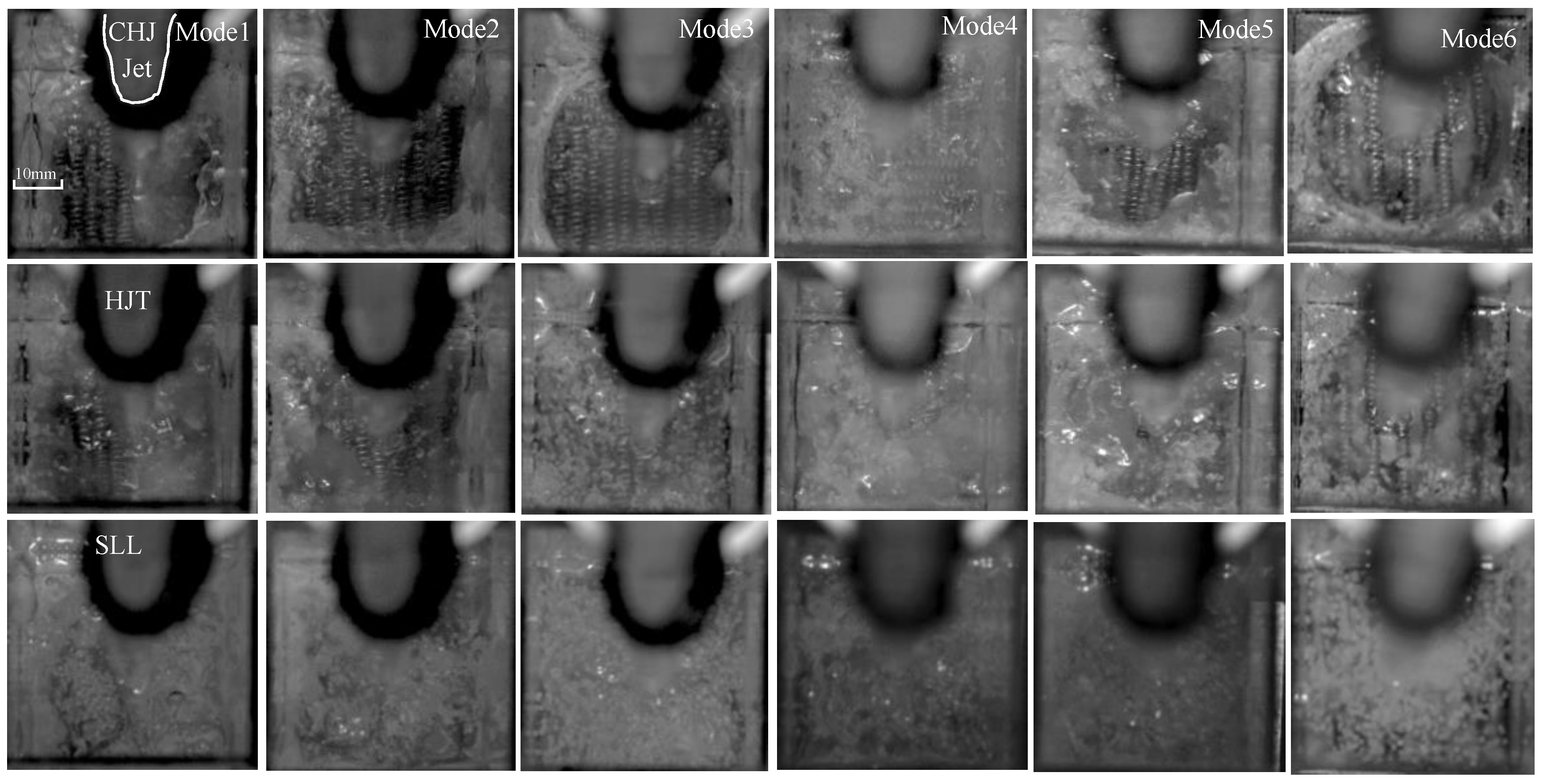
The flow field in three forms of hydraulic jump during the filling process is processed by open-source software PIVlab (PIVlab 2.53, William Thielicke, Hamburg, Germany). The flow field analysis area selected is rectangular in PIVlab. The selected area is divided into two areas by the fluctuating liquid surface: one part is liquid under the surface, and another is air above the surface. The area not analyzed is indicated by the red cross “×”; in the area analyzed, the velocity vector is indicated by the green arrow “→” (Seen in Figures 2 and 4)
In order to study the effect of solidification on the flow field, a water-cooling system is set at the mold bottom, and a sodium acetate solution is used to simulate the formation process of molten steel solidifying on the surface of the dummy bar. The specific steps are as follows:
1. During the experiment, the cooling system is working, and the springs and particles are arranged on the dummy bar/mold bottom (in
Table 1, laying one layer of particles evenly on dummy bar requires about 2 g polyethylene particles in this paper); the cooling power is constant, and the ambient temperature is maintained at 20 °C, that is, the solidification rate is unchanged.
2. Saturated sodium acetate solution is injected into the mold until it submerges the springs and particles laid at the bottom.
3. Under the action of cooling, the solidification starts rapidly from the bottom; when the solidification progresses to the set stage (slurry or semisolid), the filling starts. The hydraulic jump behavior of the filling process is observed from three angles through a high-speed camera. Meanwhile, the flow field analysis is carried out in three physical forms of hydraulic jump, namely CHJ, HJT, and SLL.
3. Results and Discussion
First, the whole hydraulic jump evolution and its two-dimensional flow field/ velocity vector are observed (
Figure 2,
Figure 3,
Figure 4 and
Figure 5). Second, the velocities at 1 mm below the liquid surface in the three forms of the hydraulic jump are quantitatively analyzed (
Figure 6,
Figure 7,
Figure 8 and
Figure 9). Finally, relationship between spring arrangement, flow and hydraulic jump are established during the filling process. (
Figure 10,
Figure 11 and
Figure 12).
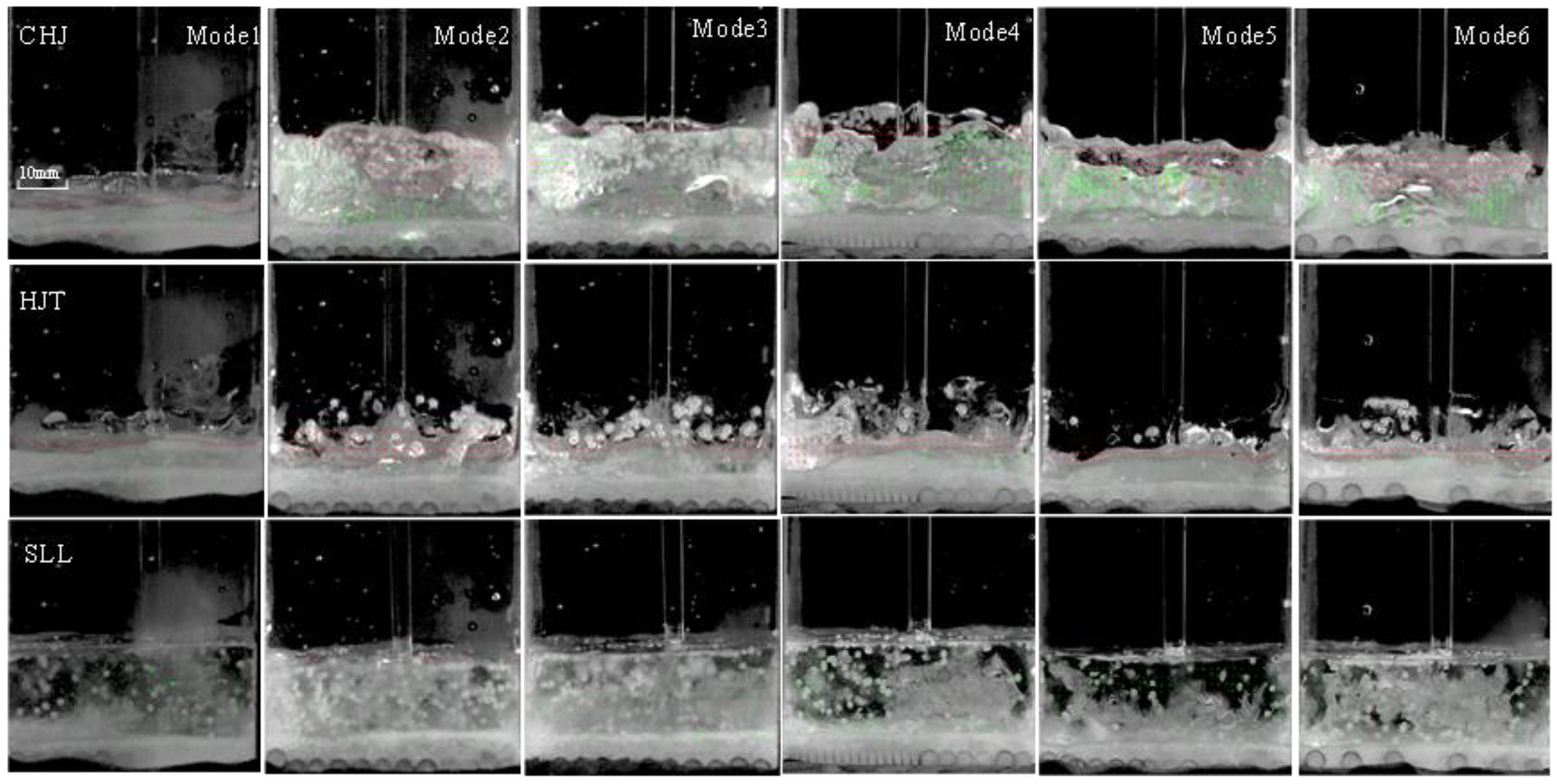
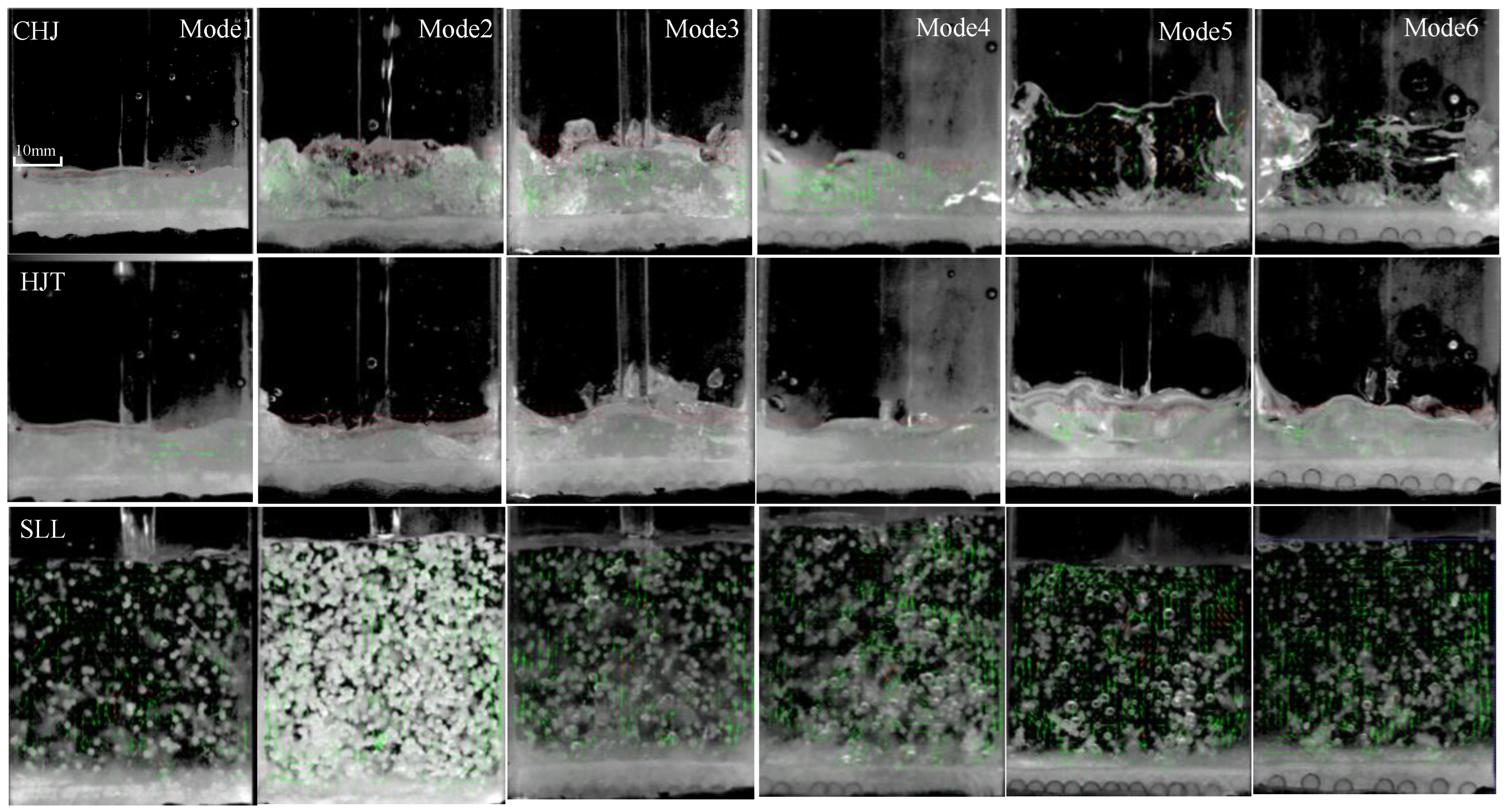
Figure 2.
Hydraulic jump form and flow field in three physical forms of hydraulic jump of front view (casting speed of 0.8 m/min, mode 1–6).
The solidification morphology and laying changes as shown in
Figure 2 and
Figure 3. The morphology of the solid–liquid interface is different with different laying modes. The solidified layer can be clearly seen, and the thickness of the solidified layer (the saturated sodium acetate capacity injected into the mold) is set in the experiment to just cover the spring, that is, the height of the solution level is nearly equal to the diameter of the spring. The water jet does not have direct contact with the laying and the solidified layer fixes the spring; obviously, this causes the spring arrangement to basically remain in its original state, with no significant movement, but the particles as iron chips move with the flow, and the hydraulic jump is fully developed despite the presence of the solidified layer. At a low casting speed of 0.8 m/min, in CHJ, the hydraulic jump height of mode 2–5 is significantly higher, and that of modes 1 and 6 is the lowest; an obvious semisolidified ring forms, the liquid level is low, and the pure-liquid phase is less; it is basically semisolidified. In HJT, it shows an obvious semisolidified state, and the liquid surface was smoother; the liquid level height of all modes is basically maintained at about 14–15 mm. In SLL, the liquid level is high enough, and the effect of the bottom solidified layer on the liquid level and surface velocity is relatively small; the thickness of the solidified layer is also basically the same, which can be explained by the thermal equilibrium between the bottom cooling and the water in the mold; the solid–liquid interface is basically flattened, which is directly related to the flow scouring in addition to thermal equilibrium. The liquid level of each mode is also basically the same in SLL.
The flow field and hydraulic jump form at the high casting speed are similar to those at a low casting speed, but the liquid level rises significantly higher at a high casting speed; since the semisolidified layer covers the spring, it increases the resistance of the spring movement and acts to fix the spring. In order to study the effect of the solid-phase fraction of the solidified layer/mushy zone on its solid–liquid interface and bulk flow, the solid-phase fraction of mode 5–6 increases (that is, the shell becomes harder, and the interface becomes smoother; due to the constant solidification rate, this is achieved by delaying the jet time to give the sodium acetate more time to be solidified). The heights of mode 5–6 are the highest in CHJ and absorb the least kinetic energy of the jet impact, while the heights of mode 1–4 are lower in CHJ and the smaller solid-phase fraction of mushy zone can better absorb kinetic energy. In SLL, the liquid level of each mode reaches 46–48 mm. The effect of the bottom solidified layer on the liquid level and surface velocity basically disappears. The mushy zone of the porous structure gradually evolves into a complete solid under the flow action of the initial spring arrangement and jet impingement, which is equivalent to a dynamically changing mode/arrangement. The initial spring arrangement is different, and the corresponding solidification morphology is also different. However, after HJT, the mushy zone gradually solidifies completely, and the morphology gradually tends to be consistent under the action of flow erosion and heat and mass transfer. Besides, some experiments wihout solidification (no saturated sodium acetate solution is injected into the mold, other experimental setups and conditions are the same) have been also done. compared with no solidification case, the flow field and hydraulic jump form with or without solidification are similar, if the thickness of the solidified layer is neglect, the liquid level height with or without solidification is basically the same at the two casting speed.
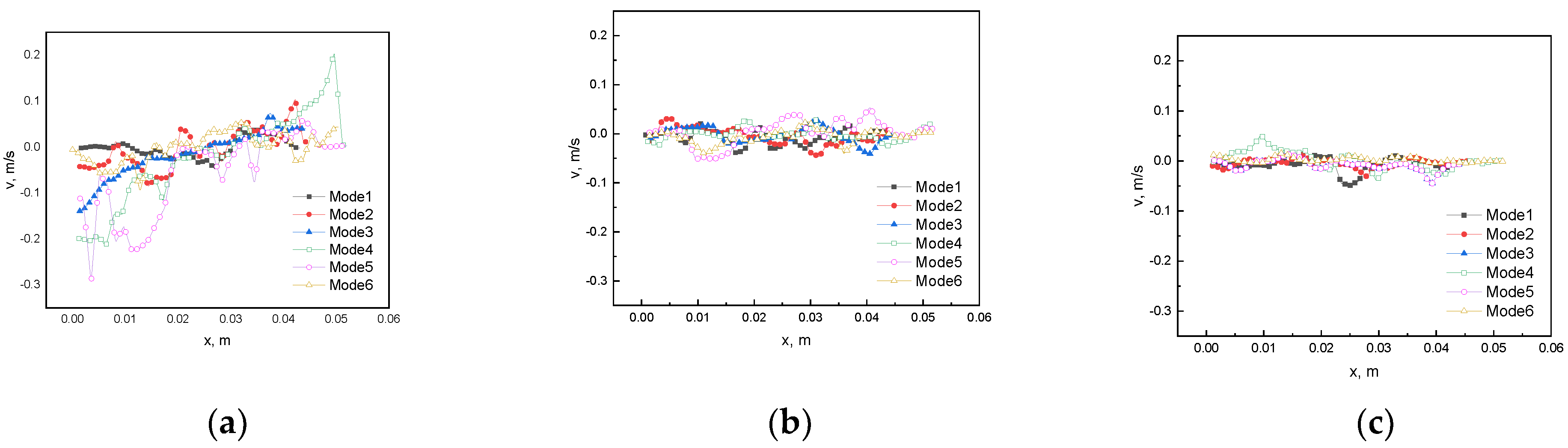
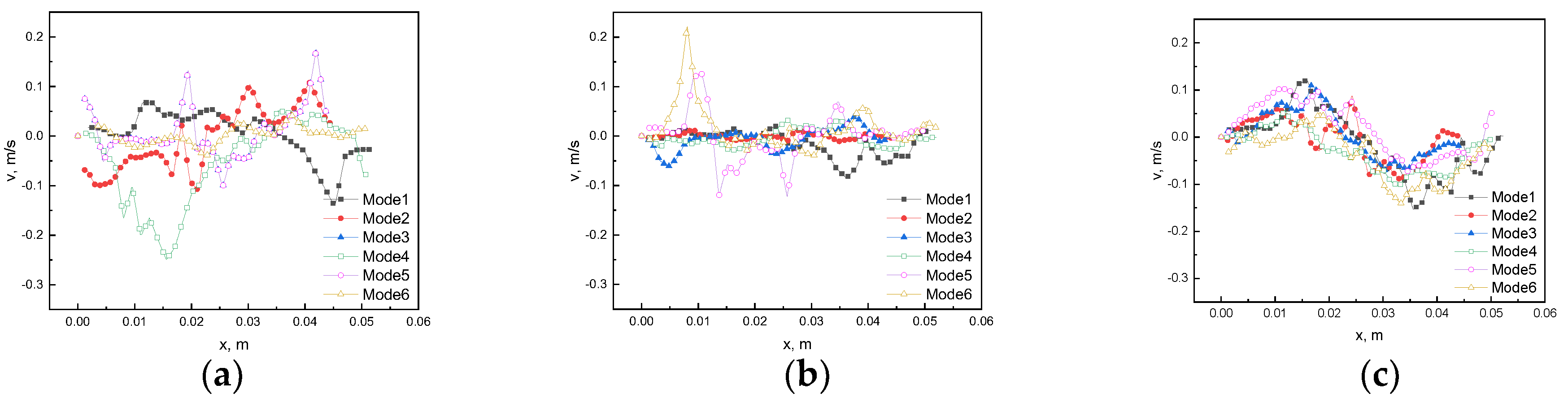
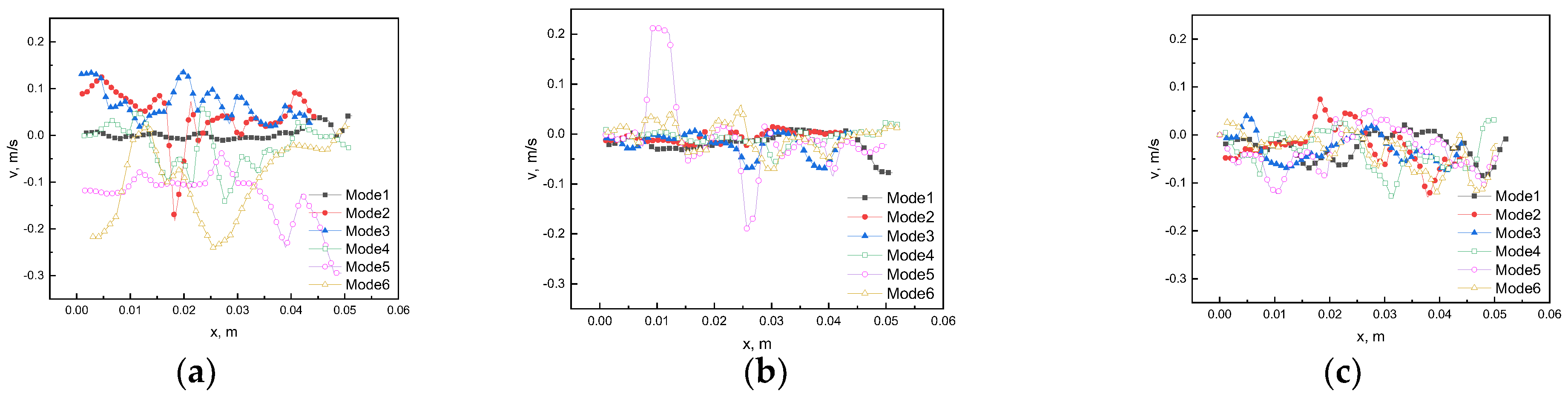
The velocity at 1 mm below liquid surface in the three forms of hydraulic jump under two casting speeds (0.8 m/min, 2.4 m/min) are shown in
Figure 6,
Figure 7,
Figure 8 and
Figure 9. The rightward velocity is defined as a positive direction (x direction). The downward velocity is defined as the positive direction (y direction).
In CHJ, with solidification, the horizontal component of velocity on the left side is negative, the horizontal component of velocity on the right side is positive, and the vertical component of velocity is mostly negative, which obviously forms the flow rushing to both sides of the wall and sputtering upward, combined with
Figure 2,
Figure 3,
Figure 4 and
Figure 5 (the velocity is also obtained by software PIVlab processing the information of the photos); without solidification, most modes have already begun to form backflow to the center of the mold. This is because solidification increases the resistance to flow and slows the progress of the hydraulic jump. After CHJ, the velocity decays rapidly.
In order to better illustrate the effect of the solid–liquid interface morphology on the hydraulic jump behavior (including height and duration), the results of the control experiments without solidification are given in
Figure 10,
Figure 11 and
Figure 12.
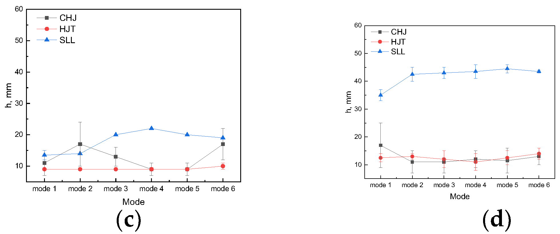
The liquid-level height of different modes at two different casting speeds with or without solidification in three hydraulic jump forms is shown in
Figure 10. It can be seen that the average liquid-level height in SLL increases with the increase in the casting speed in general, and the liquid-level height in HJT has little relationship with the mode and solidification.
The liquid level/hydraulic jump height changes as follows:
At 0.8 m/min casting speed with solidification:
CHJ: Free surface/liquid-level fluctuations of CHJ are the largest among the three forms (CHJ, HJT, and SLL); the hydraulic jump height/depth of mode 1, 6 (the hydraulic jump height is outer depth for CHJ) is the lowest and about 15 mm; the maximum height of mode 2–5 can reach 20–25 mm.
HJT: There is no obvious difference in the overall liquid profile among mode 1–6; and the average heights of liquid surface are almost the same in mode 1–6, about 15 mm.
SLL: the liquid level is relatively smooth (but this does not mean that the fluctuation velocity value around the liquid surface is small), with a height of about 25–28 mm.
At 2.4 m/min casting speed with solidification:
CHJ: Free surface/liquid-level fluctuations in CHJ are the largest among the three forms (CHJ, HJT, and SLL); the average hydraulic jump height of mode 2–6 is low and about 13 mm; the maximum height of mode 1 can reach 26 mm.
HJT: There is no obvious difference in the overall liquid profile among mode 1–6; and the average heights of liquid surface are almost the same in mode 1–6, about 15 mm.
SLL: The liquid level is also relatively smooth (but this does not mean that the fluctuation velocity value around liquid surface is small), with a height of about 39–41 mm.
At a low casting speed, the law of hydraulic jump height/liquid-level height is similar to that without solidification. In HJT, the liquid-level height has nothing to do with arrangement and solidification. In CHJ, although the heights of the liquid level with and without solidification are different, the maximum height is not much different with the same laying mode; in addition, when the liquid-level height in CHJ increases, the liquid-level height in SLL does not appear to decrease, as in the case of no solidification. In SLL, the laws of hydraulic jump height are similar with and without solidification; the maximum height is not much different. At a high casting speed, there are similar results. To study the effect of solidification, the solidified layers of mode 5, 6 are set to higher solid fractions, and the liquid level in CHJ and HJT becomes higher than that in other modes. There is no significant difference in the liquid-level height of each mode in SLL. The above results also prove that the effect of solidification is mainly before HJT.
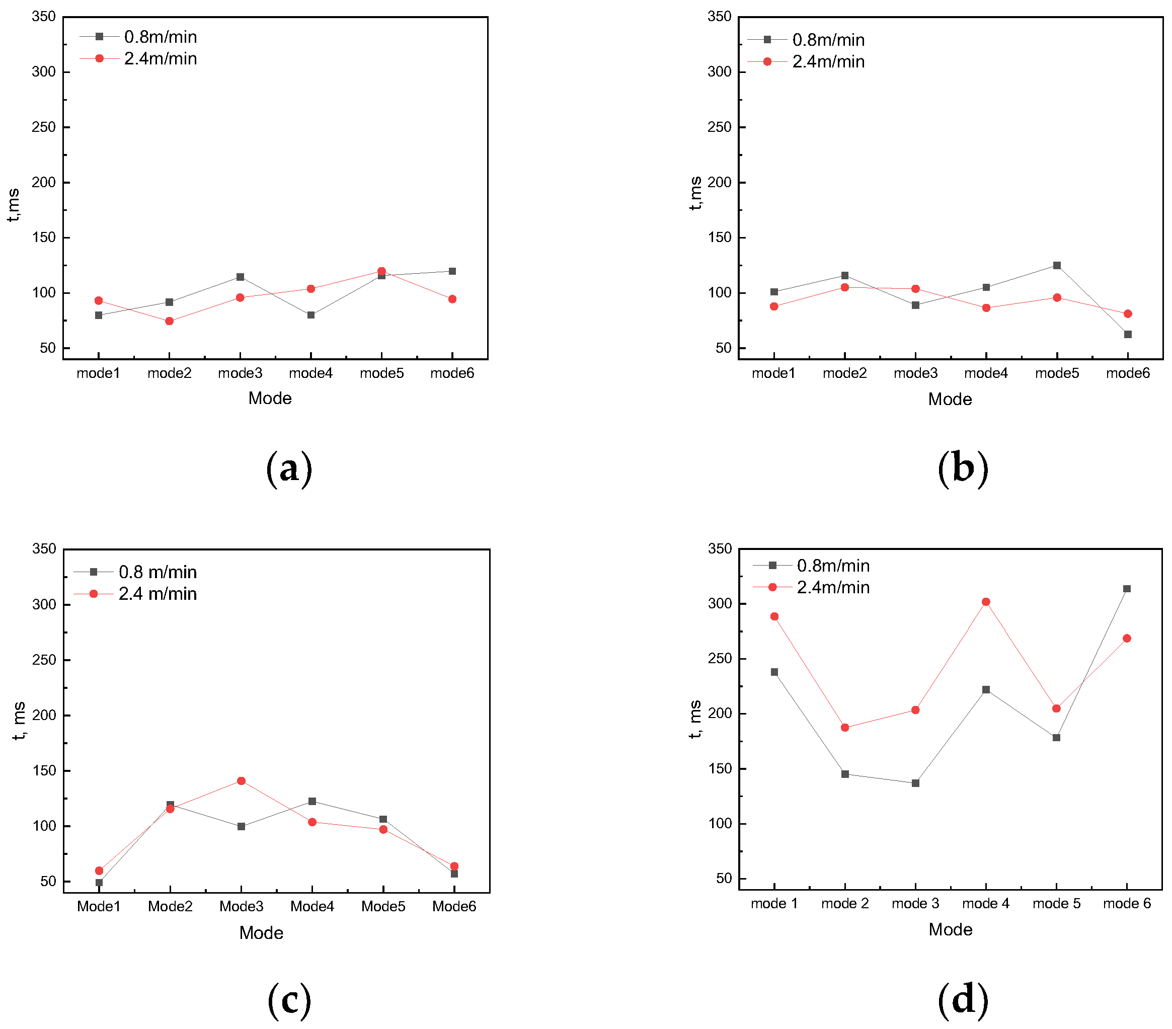
The law of duration for the three transition processes of hydraulic jump (CHJ, HJT, and SLL) with solidification is similar to that without solidification (
Figure 11). On the one hand, the flow rate has little effect on the duration of the transition time. On the other hand, the duration of the transition time is related to the solidified layer/interface morphology; the interface morphologies formed by solidification on the six laying mode are dynamic and varying, which are equivalent to six new laying modes.
The CHJ transition durations for all modes with solidification are close to those without solidification and are more uniform. CHJ-to-HJT durations for all modes with solidification are less than those without solidification. With solidification, although there are still obvious differences in the duration of different modes, the variation range is around 75–100 ms; modes 1 and 6 are not significantly lower than other modes; the law of CHJ duration tends to be consistent with that of the CHJ-to-HJT duration, that is, the transition duration converges. It is clarified that designing different arrangements can indeed adjust the hydraulic jump behavior with or without solidification. Moreover, the duration of CHJ to HJT with solidification is almost half of that without solidification. It is shown that the porous mushy zone absorbs more dynamic energy of the jet. However, these two indicators cannot yet determine which arrangement is the best.
A filling coefficient w (no dimensional velocity) is already set: w = |vF|/|vR|·|vF|—the absolute value average of the fluctuation velocity at liquid level (the average velocity at 1 mm below liquid surface) in CHJ, HJT, and SLL; |vR|—the absolute value of the average liquid level rise velocity in CHJ, HJT, and SLL. An increase in the filling coefficient w indicates an increase in fluctuation or a decrease in liquid level rise velocity. The flow field for the filling process needs to be stable and fast to fill the mold. The smaller the filling coefficient, the more the filling process meets the metallurgical goal. In addition, w has a relatively obvious correlation with flow and spring arrangement.
In the case of solidification, there is obvious law of w (
Figure 12). In general, w is largest in SLL and smallest in HJT; w is lower with solidification than that without solidification, except for mode 5, but w is the largest in HJT without solidification. The w in CHJ and HJT of mode 5 is the largest at the two casting speeds. At the high casting speed, the law of the three forms tends to be consistent, which is similar to the case without solidification. During solidification, with the increase in viscosity and resistance, the surface velocity fluctuation and the liquid level rise speed decrease, and the surface velocity fluctuation is reduced more significantly. At the same time, due to the covering of the solidified layer, the loose arrangement of mode 1 and mode 6 does not directly affect the flow field or hydraulic jump behavior, nor is it significantly improved compared with other modes without solidification.
As mentioned in the experimental process, the design of the experiment is different from the actual situation. Therefore, a better analysis of the difference between the experiment and the actual situation will lead to more effective guiding conclusions. The results with or without solidification show that after the liquid level rises to a certain height, that is, in SLL and later, the interface morphology of the solidified layer is more affected by the flow, while the interface morphology of the solidified layer has no significant effect on the liquid surface velocity. In the filling process of cast start or restart after sudden cast stop, according to the 1:4 mode experiment, the liquid-level height of the corresponding actual continuous casting can be obtained. If the liquid level reaches 100 mm at the low casting speed and 200 mm at the high casting speed, respectively (the corresponding liquid level in SLL in the model experiment is about 25 mm and 50 mm, respectively), the solidification morphology or spring arrangement on the dummy bar has no significant effect on the liquid-level behavior. Therefore, once the liquid level reaches the corresponding critical value, it is not necessary to consider the solidification morphology or spring arrangement on the dummy bar, and the flow of molten steel should be controlled by other means, such as electromagnetic fields. However, if the solid–liquid interface develops rapidly and the distance between the solid–liquid interface and the liquid surface is lower than the critical distance, then the morphology of the solid–liquid interface must be considered.
It can be seen that the morphology of the solidified layer or spring arrangement on the dummy bar has a greater effect on the flow in CHJ and HJT, and it continues to affect the subsequent flow field. The fluctuation of the liquid level (hydraulic jump height in CHJ) is very large and it can even be higher than the liquid level in SLL; in HJT, the semisolid state is dominant below the liquid surface. The increase in viscosity suppresses the flow velocity or its fluctuation, and the solidification process begins to capture bubbles and inclusions.


