Article

Specific Surface Area Evolution and Shrinkage Control of Pre-Sintered Nickel Clusters

1
Metal Powder Materials Industrial Technology Research Institute of GRINM, Beijing 101407, China
2
GRIPM Advanced Materials Co., Ltd., Beijing 101407, China
3
General Research Institute for Nonferrous Metals, Beijing 100088, China
4
Beijing GRIPM Advanced Materials Research Institute Co., Ltd., Beijing 101407, China
5
China Iron & Steel Research Institute Group, Beijing 100081, China
6
Institute for Advanced Materials and Technology, University of Science and Technology Beijing, Beijing 100083, China
*
Author to whom correspondence should be addressed.
Metals 2022, 12(10), 1693; https://doi.org/10.3390/met12101693
Submission received: 31 August 2022 / Revised: 2 October 2022 / Accepted: 6 October 2022 / Published: 10 October 2022
(This article belongs to the Special Issue Additive Manufacturing of Non-ferrous Alloys)

Abstract

:
This study prepared pre-sintered clusters with fine nickel powders and proposed an effective method to predict and control the sintering shrinkage based on cluster size. Experiments were conducted to investigate the influence of the pre-sintering temperature and cluster size on the specific surface area and morphology of pre-sintered clusters as well as to validate the availability of the proposed shrinkage prediction method. The results show that the specific surface area decreases with an increasing pre-sintering temperature and slightly oscillates with an increasing cluster size. The linear shrinkage ratio is inversely proportional to the cluster size and decreases with an increasing pre-sintering temperature, which begins to drop rapidly at 500 °C and decreases from 19.05% to 3.18% at 800 °C. The experimental results are quite approximate to the predicted values, which strongly prove the availability of the proposed shrinkage prediction method.

1. Introduction

Porous nickel materials are widely used in heat pipe wicks, catalysts and battery electrodes due to the excellent capillary performance, catalytic performance and high-temperature oxidation resistance [1,2,3]. The sintering of fine nickel powders is a significant method to manufacture porous nickel materials with small pores and high porosities, which desirably enhance the capillary pressure and permeability [4,5,6,7,8,9,10]. However, the shrinkage ratio of nickel powder during sintering is usually large and uncontrollable, which decreases the porosity and dimension accuracy of porous nickel materials [11,12,13]. The decrease in the porosity usually reduces the performance of porous nickel materials and the decrease in the dimension accuracy demands an extra machining process [11]. In this situation, the prediction and control of sintering shrinkage are significant and instructive to optimize the porosity and dimension accuracy of porous nickel materials.
The practical sintering shrinkage is usually hard to derive directly from theory models because some ideal conditions are seldom fulfilled in practice [14]. Particle size, as a key parameter of powders, has a great influence on the sintering shrinkage. On the one hand, the smaller the particle size is, the larger the specific surface area and surface energy are [15,16]. The surface energy is the main source of the driving force for sintering, and the increase in surface energy subsequently increases the sintering shrinkage [17,18,19,20]. On the other hand, the small particle size of the powder provides excellent kinetic conditions for atomic diffusion and leads to greater mass transfer, which inevitably increases the sintering shrinkage [18,21,22].
Many researchers tried to control and reduce the shrinkage ratio of ceramic materials. Reaction bonding and phase transformation sintering are two useful methods to prepare low-shrinkage ceramics, but these two methods are inapplicable to the sintering of a single nickel powder because no reaction and phase change occurs during sintering [23,24]. Lv et al. [25] introduced the pre-sintering process to prepare a low-shrinkage and high-performance alumina powder. This process reduces the linear shrinkage of alumina powder from 15–20% to 7.79%. Pre-sintered clusters are of particular benefit to manufacturing bi-dispersed porous materials due to their controllable size and the existence of internal fine pores [11,26,27,28]. To our best knowledge, there is a shortage of effective methods to control or reduce the sintering shrinkage ratio of fine nickel powders. In addition, the change in the specific surface area during pre-sintering remains to be revealed, and the effects of the pre-sintering temperature and cluster size on the specific surface area and sintering shrinkage ratio are still suspended.
In this study, we analyzed the pre-sintering process and proposed a method based on cluster size to empirically predict and control the linear shrinkage of fine nickel powders. Continuously, experiments were conducted to validate the availability of the prediction method. The influence of the pre-sintering temperature and cluster size on the morphology and specific surface area was also investigated in the experiment. Finally, the effects of the specific surface area and cluster size on the linear shrinkage ratio are discussed.

2. Theory

2.1. Atoms Movement on Particle Surfaces

Surface atoms accumulate at a point of curvature gradient κ s with an average velocity ν given by the Nernst–Einstein relation [29]:
ν = D s γ Ω k T κ s
where γ represents the surface free energy per unit area, Ω denotes the atom volume, k is the Boltzmann constant, T denotes the temperature and D s is the surface diffusion coefficient, and is depicted by Equation (2) [30]:
D s = D 0 exp ( Δ E m / k T )
where D 0 is the prefactor dependent upon the dynamics of the diffusion process, Δ E m is the activation energy for diffusion. By substituting Equation (2) into Equation (1), the accumulating velocity is given by:
ν = D 0 γ Ω k κ s e Δ E m / k T T
For a point on a convex surface, κ s is positive, and correspondingly, v   is negative, meaning that atoms disperse away from the point. Oppositely, atoms accumulate at a point on a concave surface. The absolute value of v increases with increasing κ s . Deriving v to T , the result can be written as:
ν T = D 0 γ Ω k κ s e Δ E m / k T T 2 ( Δ E m k T 1 )
It is well known that Δ E m k T 1 0 [31]. According to Equation (4), the dispersing or accumulating velocity increases with increasing temperature. The integral of v is the total mass of atoms dispersing from a convex point or accumulating at a concave point. A greater value of integral results in a smoother surface.

2.2. A Control Method of Linear Sintering Shrinkage Ratio

Figure 1 shows two kinds of clusters in the loose sintering process, namely the agglomerated clusters and the pre-sintered clusters. The primary particles of the former bond to each other through van der Waals force, while the primary particles of the latter bond to each other through sintering necks. The presence or absence of sintering necks will make great differences to the connection curvatures, further affect the grain-boundary diffusion in the subsequent sintering process and finally have a significant impact on the linear shrinkage ratio.
Specifically speaking, the sintering necks between the primary particles will reduce the connection curvature and hence retard grain-boundary diffusion [32,33]. The larger the sintering necks between primary particles, the smaller the connection curvatures, and the grain-boundary diffusion is retarded more strongly. As a result, the linear shrinkage ratio decreases with the growth of the sintering necks.
Let us consider a sample packed with agglomerated clusters; L 0 denotes the sample length. In addition, d 0 represents the diameter of each primary particle. Therefore, the number of primary particles in this length, N 0 , can be expressed as:
N 0 = L 0 d 0
In practice, L 0 is far larger than d 0 . In sintering, let ε 0 denote the minor shrinkage between any two particles. If a linear shrinkage ratio of K 0 is found, then ε 0 can be expressed as:
ε 0 = L 0 · K 0 N 0 1 = d 0 · K 0
Assume that another sample packed by pre-sintered clusters has the same length L 0 . Let d 1 represent the length of each cluster, which is prepared with the same primary particles as above. In the same sintering, a shrinkage ε 1 is produced between any two clusters, and the cluster length d 1 shrinks by a linear shrinkage ratio K . Then, the linear shrinkage ratio of the sample K can be expressed as:
K = ( N 1 1 ) · ε 1 + N 1 · d 1 · K L 0
where N 1 = L 0 d 1 , and N 1 1 ; therefore, Equation (7) can be rewritten as:
K = ε 1 d 1 + K
Further, consuming that ε 1 equals ε 0 for the same sintering process, then Equation (8) can be written as:
K = d 0 d 1 · K 0 + K
Equation (9) shows that the linear shrinkage ratio is inversely proportional to the cluster size. K 0 and K are related to the pre-sintering process and the final sintering process, which can be determined by several experiments. One can adjust the linear shrinkage ratio of samples by preparing specified pre-sintered clusters.

3. Materials and Methods

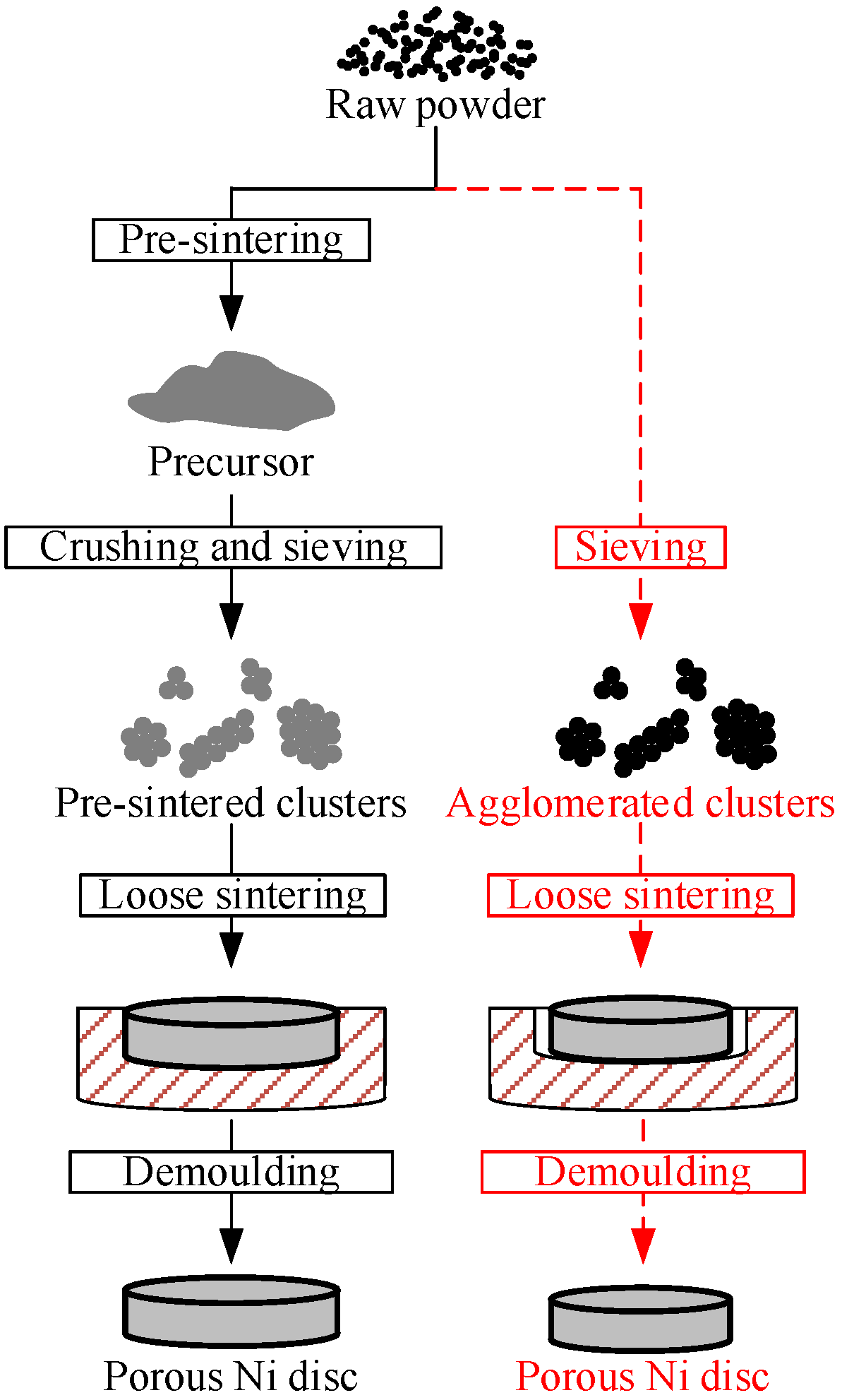
The raw material used in this study is T255 nickel powder supplied by Vale Canada Limited (Rio de Janeiro, Brazil), whose average diameter (Fisher number) is 2.8 µm, and the specific surface area is 0.56 m2/g. Figure 2 shows the experimental procedure in this study. To study the pre-sintering performance of clusters, two comparative experiments were conducted with different process methods. In the first experiment, the raw powders were pre-sintered into precursors. They were then crushed and sieved into pre-sintered clusters, according to the predetermined size range. Lastly, the pre-sintered clusters were loosely sintered in graphite dies, and then demolded to obtain the porous Ni discs. In comparison, the raw powder was sieved directly to obtain agglomerated clusters with the same size range as above, followed by the same loose sintering and demolding process. Loose sintering as the final sintering process was conducted to avoid the impact of distortion energy.
During the preparation of clusters, the influences of pre-sintering temperature and cluster size on the morphology and specific surface area were studied. The raw powders were, respectively, pre-sintered at 400 °C, 500 °C, 600 °C, 700 °C and 800 °C for 60 min. There are four predetermined cluster size ranges, namely 0–25 µm, 25–38 µm, 38–53 µm and 53–74 µm. In subsequent loose sintering, the effects of pre-sintering temperature and cluster size on linear shrinkage ratio were investigated. The clusters were loosely sintered at 800 °C for 60 min in graphite dies whose inner height and inner diameter are 3 mm and 15 mm, respectively. In the pre-sintering process and loose sintering process, a tube furnace with an accuracy of ±1 °C was utilized. In addition, a diffusion pump was connected to the tube furnace to keep a vacuum below 1.0 × 10 2 Pa.
To reveal the effect of pre-sintering temperature on the pre-sintered clusters, the morphology was observed on a field-emission scanning electron microscopy (SEM, JSM-F100, JEOL Ltd., Tokyo, Japan) and the specific surface area was determined on a nitrogen adsorption machine (JW-BK300, JWGB SCI. & TECH. Ltd., Beijing, China) in nitrogen adsorption method. The margin of error for the specific surface area is plus or minus 3%. A neck size ratio is defined as the ratio of the sintering neck dimension to the particle diameter, which increases as the sintering neck grows large [27]. In this study, the neck size ratios were statistically calculated from these SEM images. The neck dimension was measured at the most constricted part between two particles. Two best-fit circles were created based on the two adjacent particles, and the diameters of the two best-fit circles were measured and averaged to determine the particle diameter. More than 100 samples were measured to calculate the neck size ratio at a pre-sintering temperature.
The packing of clusters in the graphite dies was homogeneous, so each dimension exhibits the same shrinkage [16]. In this study, the linear shrinkage ratio is characterized as radial shrinkage ratio. In addition, the radial shrinkage ratio K p in loose sintering was calculated by Equation (10):
K p = D 0 D 1 D 0
where D 0 is the inner diameter of the graphite die while D 1 represents the diameter of the porous Ni disc, which are determined by a micrometer. More than 5 samples in each experiment were tested and averaged to determine the radial shrinkage ratio, and the error is within 0.5%.

4. Results and Discussion

4.1. Morphology of Clusters

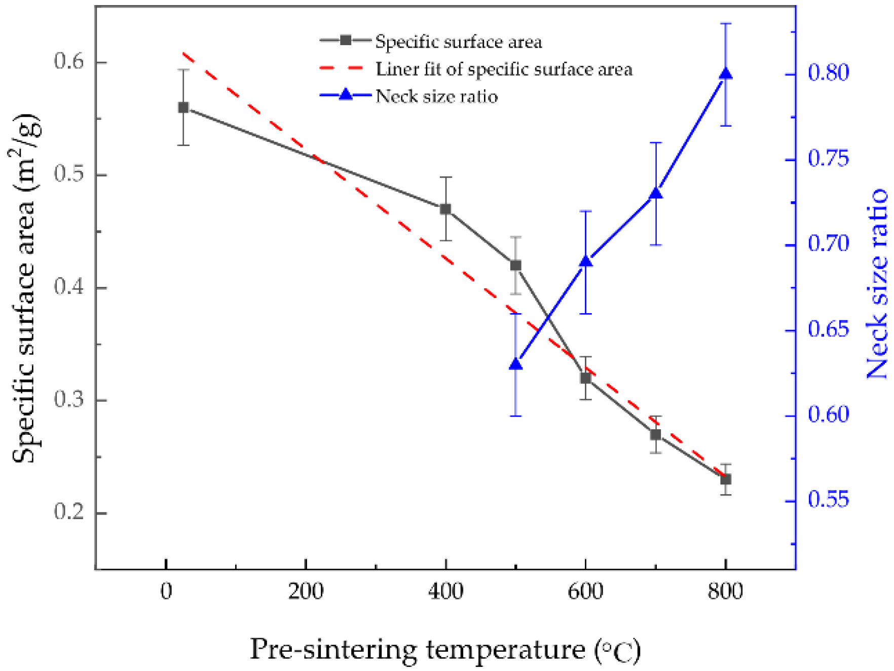
Figure 3a shows the morphology of the raw powder, while Figure 3b, Figure 3c, Figure 3d, Figure 3e and Figure 3f show the morphology of clusters, respectively, pre-sintered at the temperatures of 400 °C, 500 °C, 600 °C, 700 °C and 800 °C for 60 min. The raw powder majorly consists of filamentary agglomerated clusters, and each agglomerated cluster consists of lots of primary particles. Pre-sintered clusters present similar porous structures and possess many fine pores. However, different pre-sintering temperatures result in various sintering necks. Sintering necks form at 500 °C and gradually grow large with an increasing pre-sintering temperature. Figure 4 shows the neck size ratios of clusters pre-sintered at 500 °C, 600 °C, 700 °C and 800 °C. The neck size ratio increases as the necks grow large. The sintering necks form and grow, mainly owing to surface diffusion and grain-boundary diffusion, whose coefficients increase as the pre-sintering temperature increases. A higher pre-sintering temperature drives more atoms to accumulate at the connections and results in larger sintering necks.
The surface roughness of particles also changes as the pre-sintering temperature increases. As shown in Figure 3a, many bulges disperse on the surface of the raw powder. With increasing the pre-sintering temperature, both the density and size of the bulges decrease. As a result, the surfaces of the clusters get smoother with increasing pre-sintering temperatures. The surface atom movement in the pre-sintering process accounts for the diminishing or eliminating of the bulges. The curvature gradients at the bulges are positive; hence, atoms disperse away from the bulges. The higher the pre-sintering temperature, the faster the dispersing velocity, as described in Equation (7). For a given pre-sintering time, more atoms disperse away from the bulges at a higher pre-sintering temperature. Therefore, a higher pre-sintering temperature results in a smoother surface.
Figure 3f–h show the relationship between the morphology of the clusters and size ranges. As the cluster size increases, more primary particles are bonded together. Accordingly, more sintering necks form and grow large inside clusters. Partially enlarged drawings of Figure 3f–h show the surface roughness of these clusters. Due to the same pre-sintering temperature and time, the surface roughness is similar: the surfaces are smooth and rare bulges are detected.

4.2. Specific Surface Area

Figure 4 shows the relationship between the specific surface area and the pre-sintering temperature. The cluster size ranges from 25 µm to 38 µm. It is shown that the specific surface area decreases near linearly with an increasing pre-sintering temperature. The starting point denotes the specific surface area of the agglomerated clusters in the raw powder, whose specific surface area is 0.56 m2/g. In addition, the specific surface area of clusters pre-sintered at 800 °C decreases to 0.23 m2/g. The decrease in the specific surface area is attributed to two reasons: the sintering necks form and grow large between primary particles, and the bulges diminish and vanish. It can be seen from Figure 3 that sintering necks are generated at 500 °C. Hence, for clusters pre-sintered at 400 °C and 500 °C, the specific surface area decreases majorly because bulges diminish and vanish. As the pre-sintering temperature increases to 600 °C or above, large sintering necks are detected and only a few bulges exist. Thus, the further decrease in the specific surface area is attributed to the growth of sintering necks.
When one more primary particle is bonded to a cluster, three new necks are generated. Assume a cluster combined by N primary particles, whose number increases as the cluster size increases. For each primary particle, the mass is m 0 and the surface area is S 0 . When N is larger than 2, the number of sintering necks in the cluster is approximately 3 ( N 2 ) . In pre-sintering, assume that each sintering neck leads to a decrease in S on the total surface area, which increases as the sintering neck grows large and ranges from 0 to S 0 3 . Then, the specific surface area S can be expressed as:
S = N · S 0 3 ( N 2 ) · S N · m 0 = S 0 m 0 3 S m 0 · ( 1 2 N )
when the neck size ratio increases from 0.63 to 0.80, the specific surface area decreases from 0.42 m2/g to 0.23 m2/g (as shown in Figure 4). The decrease in the specific surface area indicates that S significantly affects the specific surface area of pre-sintered clusters.
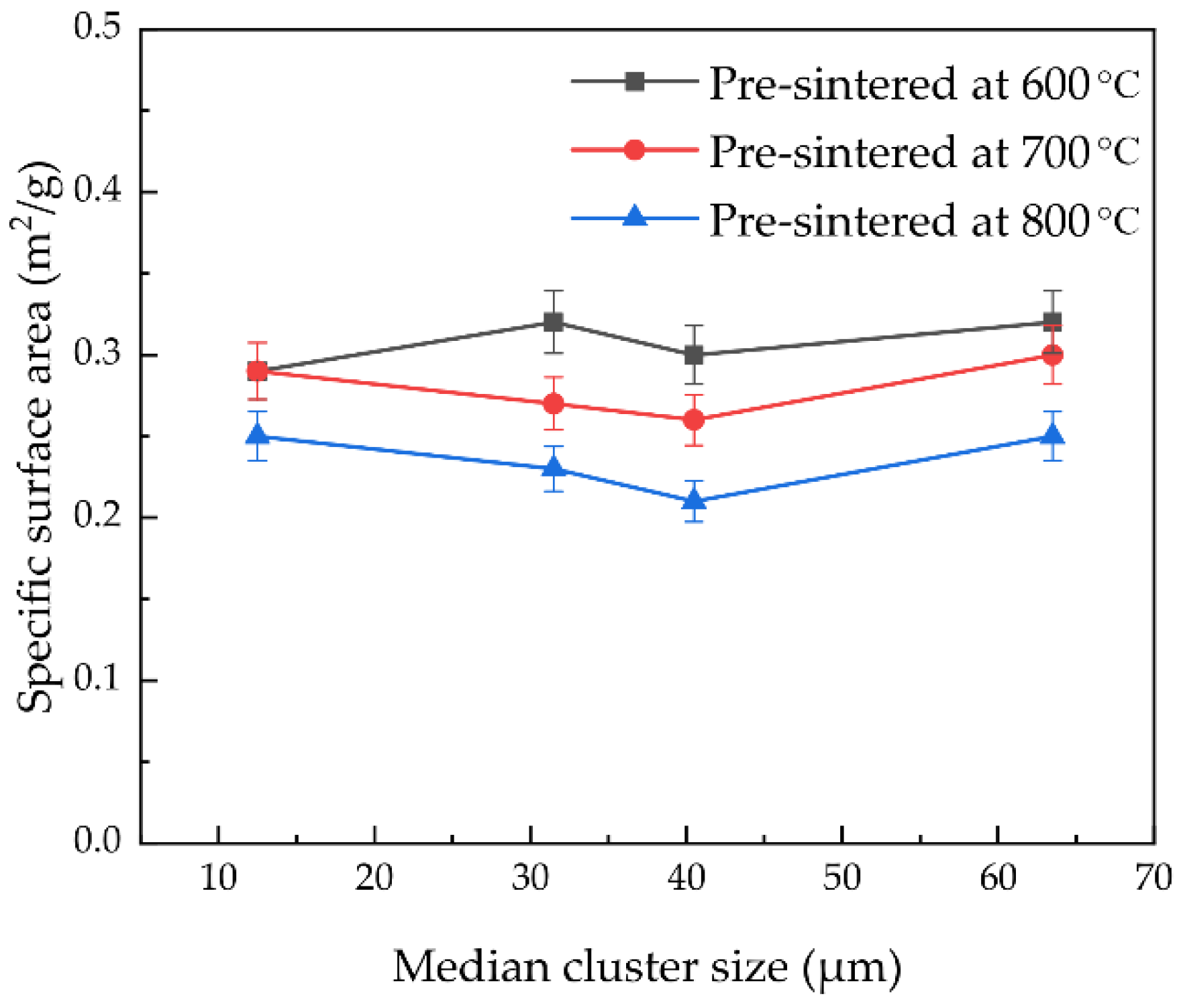
Figure 5 shows the relationship between the specific surface area and the median cluster size. It can be seen that the specific surface area of the pre-sintered clusters shows a slight oscillation with an increasing median cluster size. Meanwhile, the maximum variation of 0.04 m2/g can be neglected compared with the effect of the pre-sintering temperature, as shown in Figure 4. Therefore, we can conclude that the size of the pre-sintered clusters has little effect on the specific surface area. When the cluster size is 12.5 µm, the magnitude of N is 102. According to Equation (11), a further increase in N has little effect on the specific surface area. In this situation, the specific surface area is dominated by the neck size ratio and surface roughness. Clusters pre-sintered at the same temperature show a similar neck size ratio and surface roughness (as shown in Figure 3), which results in the oscillation of the specific surface area with an increasing cluster size.

4.3. Radial Shrinkage Ratio

Figure 6 shows the relationship between the radial shrinkage ratio of porous Ni discs and the pre-sintering temperature. Note that the starting point denotes agglomerated clusters in the raw powder, the size of all the clusters ranges from 25 µm to 38 µm and the loose sintering temperature and time are 800 °C and 60 min, respectively. It can be seen that the radial shrinkage ratio decreases as the pre-sintering temperature increases. In addition, there is a slow decrease below 400 °C and a rapid decrease above 400 °C. The specific surface area and sintering necks among primary particles account for the decrease in the linear shrinkage ratio. The specific surface area slightly decreases with the increasing of the pre-sintering temperature from 400 °C to 800 °C, which leads to a gentle decline in the sintering driving force and thus slightly reduces the radial shrinkage ratio. When the sintering necks merge at 500 °C, the grain-boundary diffusion is retarded by the sintering necks and the clusters shrink a little in the loose sintering process, leading to an additional decrease in the radial shrinkage ratio. As the sintering necks grow even larger, the grain-boundary diffusion is retarded more strongly. As a result, the radial shrinkage decreases rapidly as the pre-sintering temperature increases from 500 °C to 800 °C.
The dotted line in Figure 6 represents the linear shrinkage ratio calculated by Equation (9) without K . K 0 equals the linear shrinkage ratio of the agglomerated clusters in the raw powder, 19.05%. The average diameter size of primary particles d 0 is 2.8 µm, and the median size of clusters d 1 is 31.5 µm. By the two curves shown in Figure 6, one can derive the K pre-sintered at 600 °C, 700 °C and 800 °C, which are 8.15%, 5.07% and 2.63%, respectively.
Figure 7 shows the relationship between the radial shrinkage ratio and the median cluster size. The loose sintering temperature and time are 800 °C and 60 min, respectively. The radial shrinkage ratio decreases with an increasing median cluster size and with an increasing pre-sintered temperature for both the predicted curves and experiment results, and the smallest linear shrinkage ratio is 3.18% for the clusters pre-sintered at 800 °C in the size range of 53–74 µm. As can be seen, the practical radial shrinkage ratios quite approximate the predicted curves, and the maximum relative difference is 9.5%. It can be concluded that Equation (9) is applicable to predicting the shrinkage behavior of pre-sintered clusters.
It should be highlighted that as the size of the pre-sintered clusters increases, the specific surface area remains nearly constant while the radial shrinkage ratio decreases. The fact reveals that in the loose sintering process, the decrease in the surface area adjacent to the cluster contacts (as shown in Figure 1) drives the grain-boundary diffusion and causes shrinkage between the clusters, while the decrease in the remaining surface area drives the surface diffusion and contributes little to the shrinkage. As the cluster size increases, although the specific surface area remains stable, the proportion of the former decreases. As a result, the linear shrinkage ratio decreases as the cluster size increases.

5. Conclusions

Based on the pre-sintered cluster size, the shrinkage prediction method during the final sintering process has been established in this study. The experiments were conducted to investigate the influence of the pre-sintering temperature and cluster size on the specific surface area and morphology of pre-sintered clusters as well as to validate the availability of the proposed shrinkage prediction method.
The experiment results show that the pre-sintering temperature, rather than the cluster size, greatly affects the specific surface area. With increasing the pre-sintering temperature to 500 °C, the surfaces of the clusters turn from initially rough into smooth, and sintering necks start to form, which decreases the specific surface area from 0.56 m2/g to 0.42 m2/g. As the pre-sintering temperature further increases to 800 °C, the sintering necks keep growing, which further decreases the specific surface area to 0.23 m2/g. As the size of the pre-sintered clusters increases, the increase in the number of sintering necks per unit mass is so slight that it rarely impacts the specific surface area. In this situation, the neck size ratio and surface roughness determine the specific surface area.
The pre-sintering temperature and cluster size have a great influence on the linear shrinkage ratio. As obvious sintering necks come into existence at the pre-sintering temperature of 500 °C, the grain-boundary diffusion is retarded during the final sintering process. As a result, the linear shrinkage ratio begins to drop rapidly at the pre-sintering temperature of 500 °C. Moreover, the shrinkage ratio is inversely proportional to the cluster size and the smallest linear shrinkage ratio is 3.18% for clusters pre-sintered at 800 °C in the size range of 53–74 µm. The experimental results are quite approximate to the predicted values, which strongly prove the availability of the proposed shrinkage prediction method.

Author Contributions

Investigation, F.Z. and L.W. (Linshan Wang); writing—original draft, F.Z.; visualization, F.Z.; methodology, L.W. (Linshan Wang), S.Z., L.Z., Q.H. and L.W. (Limin Wang); writing—review and editing, L.W. (Linshan Wang), S.Z. and L.Z. All authors have read and agreed to the published version of the manuscript.

Funding

This study was supported by the National Key Research and Development Program of China (No. 2021YFB3701905).

Institutional Review Board Statement

Not applicable.

Informed Consent Statement

Not applicable.

Data Availability Statement

Not applicable.

Conflicts of Interest

The authors declare no conflict of interest.

References

  1. Mishra, D.K.; Saravanan, T.T.; Khanra, G.P.; Girikumar, S.; Sharma, S.C.; Sreekumar, K.; Sinha, P.P. Studies on the processing of nickel base porous wicks for capillary pumped loop for thermal management of spacecrafts. Adv. Powder. Technol. 2010, 21, 658–662. [Google Scholar] [CrossRef]
  2. Wang, Z.B.; Chen, J.; Liu, R.T.; Li, H.; Lin, X.Y.; He, D.; Xiong, X. Preparation of an ultrafine nickel powder by solid-phase reduction with a NaCl separator agent. Adv. Powder. Technol. 2020, 31, 3433–3439. [Google Scholar]
  3. Fedorova, Z.A.; Danilova, M.M.; Zaikovskii, V.I. Porous nickel-based catalysts for tri-reforming of methane to synthesis gas: Catalytic activity. Mater. Lett. 2020, 261, 127087. [Google Scholar] [CrossRef]
  4. Guo, C.S.; Jiang, C.; Ma, J.; Cao, Y.W.; Zou, Y.; Liu, Y. Experimental study on comprehensive performance of sintering biporous wicks prepared by salt dissolution and cold pressing process. J. Heat Transf. 2020, 142, 011902. [Google Scholar] [CrossRef]
  5. Qu, Y.; Zhou, L.; Zhang, K.F.; Tian, Y. Effects of multiple sintering parameters on the thermal performance of bi-porous nickel wicks in loop heat pipes. Int. J. Heat Mass Transf. 2016, 99, 638–646. [Google Scholar] [CrossRef] [Green Version]
  6. Cao, Y.W.; Guo, C.S.; Wu, D.T.; Zou, Y. Effects of pore structure characteristics on performance of sintered bi-porous Ti3AlC2 wicks. Mater. Res. Express 2021, 8, 015602. [Google Scholar] [CrossRef]
  7. Zhang, Z.K.; Zhao, R.Z.; Liu, Z.C.; Liu, W. Application of biporous wick in flat-plate loop heat pipe with long heat transfer distance. Appl. Therm. Eng. 2021, 184, 116283. [Google Scholar] [CrossRef]
  8. Wang, C.X.; Li, Y.W.; Li, D.T.; Wang, Y.J.; Cheng, Y.J. Miniature vacuum leak element made with porous nickel sheet. Vacuum 2018, 158, 146–151. [Google Scholar] [CrossRef]
  9. Ryi, S.K.; Park, J.S.; Kim, S.H.; Hong, S.C.; Kim, D.W. Development of porous nickel membrane made by uniaxial pressing for hydrogen separation. Desalination 2006, 200, 213–215. [Google Scholar] [CrossRef]
  10. Li, H.; Liu, Z.C.; Chen, B.B.; Liu, W.; Li, C.; Yang, J.G. Development of biporous wicks for flat-plate loop heat pipe. Exp. Therm. Fluid Sci. 2012, 37, 91–97. [Google Scholar] [CrossRef]
  11. Singh, R.; Nguyen, T.; Mochizuki, M. Capillary evaporator development and qualification for loop heat pipes. Appl. Therm. Eng. 2014, 63, 406–418. [Google Scholar] [CrossRef]
  12. Shigeno, K.; Tezuka, M. Examination of non-shrinkage firing using low-temperature co-fired alumina containing a small quantity of Cu-Ti-Nb-Ag-O additive. Int. J. Appl. Ceram. Technol. 2020, 17, 713–721. [Google Scholar] [CrossRef]
  13. Espinosa, F.A.D.; Peters, T.B.; Brisson, J.G. Effect of fabrication parameters on the thermophysical properties of sintered wicks for heat pipe applications. Int. J. Heat Mass Transf. 2012, 55, 7471–7486. [Google Scholar] [CrossRef]
  14. Jernot, J.P.; Coster, M.; Chermant, J.L. Model of variation of the specific surface area during sintering. Powder Technol. 1981, 30, 21–29. [Google Scholar] [CrossRef]
  15. Huang, Y.H.; Jiang, D.L.; Zhang, J.X.; Chen, Z.M.; Lin, Q.L.; Huang, Z.R. Sintering kinetics of YAG ceramics. J. Rare Earths 2014, 32, 416–422. [Google Scholar] [CrossRef]
  16. German, R.M. Sintering: From Empirical Observations to Scientific Principles; Butterworth-Heinemann: Oxford, UK, 2014. [Google Scholar]
  17. Zeng, L.; Sun, H.J.; Peng, T.J.; Zheng, W.M. The sintering kinetics and properties of sintered glass-ceramics from coal fly ash of different particle size. Results Phys. 2019, 15, 102774. [Google Scholar] [CrossRef]
  18. Deng, S.H.; Li, J.N.; Li, R.D.; Zhao, H.J.; Yuan, T.; Li, L.B.; Zhang, Y.J. The effect of particle size on the densification kinetics of tungsten powder during spark plasma sintering. Int. J. Refract Met. Hard Mater. 2020, 93, 105358. [Google Scholar] [CrossRef]
  19. Matsui, K.; Matsumoto, A.; Uehara, M.; Enomoto, N.; Hojo, J. Sintering kinetics at isothermal shrinkage: Effect of specific surface area on the initial sintering stage of fine zirconia powder. J. Am. Ceram. Soc. 2007, 90, 44–49. [Google Scholar] [CrossRef]
  20. Han, Y.; Fan, J.L.; Liu, T.; Cheng, H.C.; Tian, J.M. The effects of ball-milling treatment on the densification behavior of ultra-fine tungsten powder. Int. J. Refract Met. Hard Mater. 2011, 29, 743–750. [Google Scholar] [CrossRef]
  21. Coble, R.L. Initial sintering of alumina and hematite. J. Am. Ceram. Soc. 1958, 41, 55–62. [Google Scholar] [CrossRef]
  22. Kothari, N.C. The effect of particle size on sintering kinetics in alumina powder. J. Nucl. Mater. 1965, 17, 43–53. [Google Scholar] [CrossRef]
  23. Heydecke, G.; Butz, F.; Binder, J.R.; Strub, J.R. Material characteristics of a novel shrinkage-free ZrSiO4 ceramic for the fabrication of posterior crowns. Dent. Mater. 2007, 23, 785–791. [Google Scholar] [CrossRef] [PubMed]
  24. Karunaratne, B.S.B.; Kim, H.D. Fabrication of low cost shirinkage-free porous sialon ceramics. J. Ceram. Process. Res. 2009, 10, 581–588. [Google Scholar]
  25. Lv, L.; Lu, Y.J.; Zhang, X.Y.; Chen, Y.G.; Huo, W.L.; Liu, W.; Yang, J.L. Preparation of low-shrinkage and high-performance alumina ceramics via incorporation of pre-sintered alumina powder based on Isobam gelcasting. Ceram. Int. 2019, 45, 11654–11659. [Google Scholar] [CrossRef]
  26. Cao, X.L.; Cheng, P.; Zhao, T.S. Experimental study of evaporative heat transfer in sintered copper bidispersed wick structures. J. Thermophys. Heat Transf. 2002, 16, 547–552. [Google Scholar] [CrossRef]
  27. Semenic, T.; Lin, Y.Y.; Catton, I. Thermophysical properties of biporous heat pipe evaporators. J. Heat Transf. 2008, 130, 022602. [Google Scholar] [CrossRef]
  28. Byon, C.; Kim, S.J. Capillary performance of bi-porous sintered metal wicks. Int. J. Heat Mass Transf. 2012, 55, 4096–4103. [Google Scholar] [CrossRef]
  29. Jost, W. Diffusion in Solids, Liquids, Gases; Academic Press: New York, NY, USA, 1952. [Google Scholar]
  30. Ehrlich, G.; Stolt, K. Surface diffusion. Annu. Rev. Phys. Chem. 1980, 31, 603–637. [Google Scholar] [CrossRef]
  31. Skorokhod, V.V.; Ranneva, G.O. Study of the sintering of nickel powders produced by different methods. Powder Metall. Met. Ceram. 1963, 2, 194–198. [Google Scholar] [CrossRef]
  32. Luo, W.D.; Pan, J.Z. Effects of surface diffusion and heating rate on first-stage sintering that densifies by grain-boundary diffusion. J. Am. Ceram. Soc. 2015, 98, 3483–3489. [Google Scholar] [CrossRef] [Green Version]
  33. Bross, P.; Exner, H.E. Computer simulation of sintering processes. Acta Metall. 1979, 27, 1013–1020. [Google Scholar] [CrossRef]
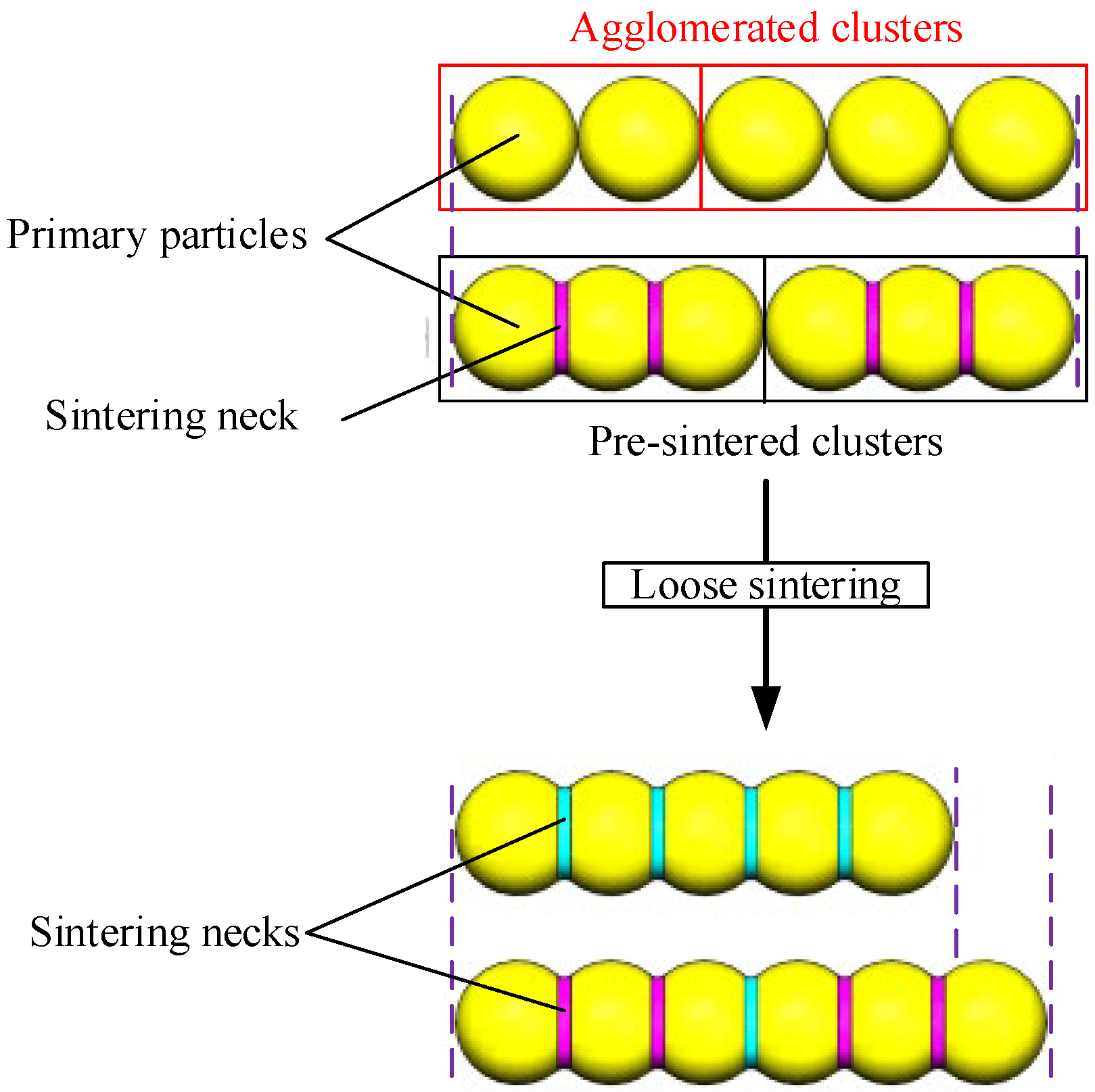
Figure 1. Shrinkage differences between pre-sintered clusters and agglomerated clusters.
Metals 12 01693 g001
Figure 2. Schematic illustration of the experimental procedure.
Metals 12 01693 g002
Figure 3. Morphology of raw powder and different pre-sintered clusters: (a) the raw powder, (b) pre-sintered at 400 °C, 25–38 µm, (c) pre-sintered at 500 °C, 25–38 µm, (d) pre-sintered at 600 °C, 25–38 µm, (e) pre-sintered at 700 °C, 25–38 µm, (f) pre-sintered at 800 °C, 25–38 µm, (g) pre-sintered at 800 °C, 0–25 µm, (h) pre-sintered at 800 °C, 38–43 µm.
Metals 12 01693 g003
Figure 4. Specific surface area and neck size ratio versus pre-sintering temperature.
Metals 12 01693 g004
Figure 5. Specific surface area versus median cluster size.
Metals 12 01693 g005
Figure 6. Radial shrinkage ratio versus pre-sintering temperature.
Metals 12 01693 g006
Figure 7. Radial shrinkage ratio versus median cluster size.
Metals 12 01693 g007
Publisher’s Note: MDPI stays neutral with regard to jurisdictional claims in published maps and institutional affiliations.