Review

Understanding Fe-Containing Intermetallic Compounds in Al Alloys: An Overview of Recent Advances from the LiME Research Hub

1
Brunel Centre for Advanced Solidification Technology (BCAST), Brunel University London, Uxbridge, Middlesex UB8 3PH, UK
2
School of Materials, University of Manchester, Manchester M13 9PL, UK
*
Author to whom correspondence should be addressed.
Metals 2022, 12(10), 1677; https://doi.org/10.3390/met12101677
Submission received: 19 August 2022 / Revised: 26 September 2022 / Accepted: 26 September 2022 / Published: 6 October 2022

Abstract

:
Control of Fe in Al alloys is a severe challenge for the full metal circulation to produce the recycled alloys with mechanical and physical performance as high as the primary alloys. The high restriction of Fe content is mainly due to the deterioration caused by the large-scale Fe-containing intermetallic compounds (FIMCs) in Al alloys. In this paper, recent knowledge gained regarding nucleation, formation, and technical developments on microstructural control and refinement of FIMCs are overviewed. Specific characteristics of the multiple types of FIMCs in Al alloys are presented in two- and three- dimensional (2D and 3D) form. Phase relationships between the FIMCs in different structures, such as primary phase, binary eutectic, and ternary eutectic, formed at different solidification stages are studied. Phase transformations between the FIMCs with or without intermediate phases during the solidification process are examined in different Al alloys, with the mechanisms being clarified. Various approaches to microstructural control of FIMCs are proposed and validated. Significant refinement of FIMCs has been achieved through inoculation of TiB2 particles that had been previously modified with deliberately interfacial segregation of desirable alloying elements, leading to the development of the novel “compositional templating” concept.

1. Introduction

With the increasing international attention on environmental protection and climate change, recycling of metallic materials becomes a more important process throughout the value chain. Metallic materials can be in theory recycled infinitely without degradation. Compared to the extraction route (primary Al), recycling of Al scrap (secondary Al) saves up to 95% of the energy and avoids significant emission of greenhouse gases [1]. Full metal circulation represents a step-change in the way that the metallic resources being used, in which the global demand for metallic materials is met by a full circulation of secondary metals through reduced usage, reuse, remanufacture, closed-loop recycling and effective recovery of secondary metals [2,3,4,5,6,7]. Critical to the full metal circulation is producing secondary alloys with comparable or better mechanical and physical performance to those of primary alloys [1,8,9].
Al is the most recyclable metallic material. Its recycling benefits present and future generations by conserving energy and other natural resources. However, at present, primary Al is mainly used for producing premium-quality Al alloys. Controlling Fe in Al alloys is a serious challenge since its gradual accumulation during repeated scrap recycling will result in deterioration in mechanical properties, especially ductility. The technical difficulties and economic cost to remove Fe from Al alloys increases with decreasing Fe content. Most Al-alloy production requires tight composition control on iron. For example, Fe content level above 0.15 wt.% is unacceptable in premium aerospace alloys, such as 7050 and 7475. Both Fe and silicon are strictly limited to 0.40 wt.% as the maximum in high-performance automotive alloys, such as 5474 and 6111 [10,11,12]. The tight restriction of Fe content is mainly due to the deterioration caused by the large-scale and harmful Fe-containing intermetallic compounds (FIMCs) in Al alloys [13,14,15,16,17,18]. In particular, above a critical Fe content (about 0.5 wt.%), the ductility of Al alloy decreases significantly. The FIMCs have different morphologies, such as plate-like, compacted, Chinese script or needle-like, which easily grow into large particles, deteriorating the mechanical properties of Al alloys. Therefore, to realize the full circulation of Al alloys, increasing the tolerance of such impurities as Fe is of critical importance in technical development required in Al recycling.
Due to the very low solid solubility of Fe in Al, secondary phases usually form in Al alloys [19]. During the past few decades, more than 20 different FIMCs have been reported to exist in various Al alloys. In cast Al alloys, there are a few of common types of FIMCs, including β-Al5FeSi (β for short), α’-Al8Fe2Si (α’ for short), α-Al15(Fe, Mn)3Si2 (α for short), δ-Al4FeSi2 (δ for short), θ-Al13Fe4 (θ for short), and η-Al6Mn (or η-Al6(Fe, Mn) (η for short), etc. As reported in the literature, the primary β-Al5FeSi [20] and θ-Al13Fe4 [21] have monoclinic crystal structures and a plate-like morphology [22,23,24,25,26]. The primary η-Al6(Fe, Mn) phase has an orthorhombic crystal structure [27] and a hollow needle-like morphology as primary phase, whilst the same η-Al6(Fe, Mn) phase in a eutectic structure has a Chinese script morphology instead [28,29]. The α-Al15(Fe, Mn)3Si2 has a body-centred cubic (BCC) structure [30]. It is reported that the BCC-α contains 138 atoms in one unit cell. The atomic positions and site occupancy are very complex due to the multi-component and variable compound concentration. It has a compacted morphology as the primary phase [31,32,33] but a Chinese script morphology in a eutectic structure. The α’-Al8Fe2Si has a complex hexagonal structure [34]. Similar to that of α-Al15(Fe, Mn)3Si2, it has a compact morphology as primary phase and Chinese script morphology as eutectic structures. δ-Al4FeSi2 phase with a tetragonal structure [35] was reported as a metastable phase that was always competitive in growth with β-Al5FeSi [36]. Intermetallic compounds of large size and in a morphology of plates or needles are extremely harmful to the mechanical performance of the Al alloys, especially the ductility. The α-Al15(Fe, Mn)3Si2 was usually considered to be less harmful due to its compacted morphology. However, researchers [31,32,33] have demonstrated that, except the primary α-Al15(Fe, Mn)3Si2 with a compact morphology and a relatively fine size, the α phase in eutectic structures normally have a Chinese script morphology and can grow to a very large scale (a few hundred micrometres or more) in three dimensional form, which is undesirable for mechanical properties. Therefore, the morphological control and refinement of these FIMCs are very important to improve the mechanical properties, particularly of the secondary Al alloys where Fe content is high.
Research efforts have been focused on different approaches to eliminate the harmfulness of Fe in Al alloys [37,38,39,40,41,42,43]. Technologically, physical processes, such as plastic deformation [37,38], ultrasonic vibration [39,40], and electromagnetic stirring [41], were employed to break up and/or refine such FIMCs with some degree of success over the last few decades. Plastic deformation during thermomechanical processing resulted in aligned FIMCs with a reduced particle size, from a few tens of micrometres to a few micrometres [37]. Ultrasonic vibration [39,40] and electromagnetic stirring [41] provide intensive forced convection during solidification processing and have been reported to be beneficial to the phase transition from the platelet-like β-Al5FeSi to the more compact or Chinese script α-Al15(Fe, Mn)3Si2 or α’-Al8Fe2Si. In addition, most of the previous research in the literature has been concentrated on the addition of selected elements (e.g., Mn, Cr, Co, Sr, Li, and K) to modify the morphology of the Fe-containing IMCs from platelet to polyhedral to reduce their harmful effect on mechanical properties [44,45,46,47,48,49,50,51,52,53,54,55,56,57,58,59,60,61]. For instance, Mn addition to a certain level where the Fe/Mn ratio is lower than 2:1 can promote the transition from platelet β-Al5FeSi to polyhedral α-Al15(Fe, Mn)3Si2 [58,59,60,61]. Small plate-like FIMCs such as β-Al5FeSi can be subsequently refined following heat treatment, although heat treatment may only be used with limited success to achieve an ideal distribution and morphology of FIMCs. Moreover, heat treatment cannot refine most types of FIMCs. Deformation can only result in limited refinement of the FIMCs, and is limited to the wrought alloys but not casting alloys. For cast Al alloys, the most effective way to refine the FIMCs is microstructural control during solidification processing. Research has been done on heterogeneous nucleation of FIMCs on oxide films/particles [62], TiB2[63], or other exogeneous particles [64,65], although significant work is still required to understand and thus control nucleation and growth of FIMCs.
Experimental results [66,67,68,69,70] have shown that phase competition of the FIMCs during the casting process is complicated. These FIMCs have different crystal structures, different compositions, and different morphologies, and they form readily together accompanying different types of phase transformations between them [71,72,73]. Few studies and little evidence can be found in the literature on the understanding of the heterogeneous nucleation of FIMCs, the relationship between different types of FIMCs, and the phase transformation between these phases. The studies on FIMCs in the literature were mainly focused on the crystallographic identification of the types of FIMCs, phase transformation phenomena, and technical development for the microstructural control and grain refinement of FIMCs. Most of the technical developments of FIMCs are based on applying existing successful techniques for pure or solid solution phases, such as Al-5Ti-1B application. Few desirable results were achieved because the formation of FIMCs is much more difficult than that of pure phases. The difficulties in the research of the FIMCs are from different aspects. All the FIMCs have very complicated crystal structures. The highly varying compositions of these compounds (Section 2) make the crystallography and chemistry even more complicated, giving rise major challenges in the research.
Currently, there is a big gap in the understanding of nucleation and formation of FIMCs, and therefore little progress in the microstructural control and refinement of the FIMCs has been achieved. The following two fundamental understandings on FIMCs are very important, providing the basis for the development of effective approaches to microstructural control and grain refinement. The first one is interpretation of the complexity in heterogeneous nucleation of FIMCs, involving the multiple constituent elements, complex structure, and various nucleation substrates, such as native oxide inoculants or the added nucleation particles. The second one is the revelation of the composition and crystallographic relationship between the different FIMCs to understand the phase transition/competition. Understanding the nucleation and formation not only benefits research on FIMCs in Al alloys but also benefits research on other types of IMCs in the other alloys.
To mitigate the harmful effect of the large-scale FIMCs and improve the mechanical properties of Al alloys, in the Liquid Metal Engineering (LiME) Research Hub [3] funded by the Engineering and Physical Sciences Research Council (EPSRC) in the UK, some holistic strategies for dealing with Fe in Al alloys have been developed. Excessive Fe (>0.5%) in recycled Al alloys can be removed effectively and economically by a novel de-ironing technique deploying intensive melt shearing [74,75], and ten residual Fe (<0.5%) will be handled by eliminating the harmful effect of such residual Fe instead of getting rid of Fe itself. The latter is achieved in the LiME Hub by the following two approaches:
  • Controlling the nucleation and growth process so to produce primary FIMCs with a compact morphology and a fine particle size; and
  • Controlling the growth morphology of α-Al dendrite (e.g., reducing the second dendrite arm spacing) to disperse finely and uniformly the eutectic FIMCs between the dendrite arms. This can be achieved by either applying intensive melt shearing [76] or adding selected minor alloying elements [77].
In this paper, a concise overview on the first approach is provided, i.e., controlling the nucleation and growth process of primary FIMCs to deliver a compact morphology and a fine particle size, and hence to reduce/eliminate the harmful effect of FIMCs.

2. Characteristics of and the Relationship between FIMCs

Different types of FIMCs in Al alloys were reported with varying morphologies, compositions, and crystal structures. Six types of most common FIMCs in the cast Al alloys were reviewed and are listed in Table 1. It shows that these FIMCs have complicated crystal structures, such as monoclinic, complex hexagonal, complex cubic, tetragonal and orthorhombic [20,21,27,30,34,35]. These crystal structures have different atomic positions designated for specific elements, some of which can be shared with multiple types of alloy elements. For example, transition elements, such as Mn and Cr, can substitute the Fe sites, and Si can substitute the Al sites. This characteristic not only changes the lattice parameters but also the morphologies of FIMCs. Such compositional variations may even cause phase transformation, making microstructural control more difficult. In the past century, the Al industry has developed over 400 grades of Al alloys with varying alloy compositions, leading to a rich variety of FIMCs. Therefore, a clear understanding of the morphology, composition and crystallographic relationship of these basic FIMCs is critical to controlling their formation and impact on mechanical properties.
There are some commonly accepted understandings on the morphology of FIMCs in the literature. For example, β-Al5FeSi, θ-Al13Fe4 and δ-Al4FeSi2 have plate-like morphology. The morphology of some FIMCs is completely different when they are present in different structures. For example, α-Al15(Fe,Mn)3Si2 has a compact morphology as primary FIMC, but Chinese script morphology in the binary eutectic form. Controversies exist on interpretation of the relationships between the different morphologies of the same FIMCs. In addition, it is difficult to distinguish different FIMCs when they have a similar morphology, such as the plate-like β and δ, which are easily formed together. In this paper, the morphology, composition and crystallography of six types of the most common FIMCs present in cast Al alloys were overviewed, and outcomes are presented in Figure 1, Figure 2 and Figure 3 and Tables 3 and 4. The experimental Al alloys investigated in this paper are listed in Table 2. The melting temperature (TL) and the equilibrium phases of each Al alloy were calculated with Pandat software using the PanAluminum 2020 database [78] under a Scheil model [79]. The casting (pouring) temperature (TP) of each alloy is about 50 °C above the calculated melting temperature. To understand the typical morphology of multiple types of FIMCs in cast Al alloys, their crystallographic characteristics were investigated with the TEM and X-ray analysis and the results are summed up in Table 3 and Table 4.

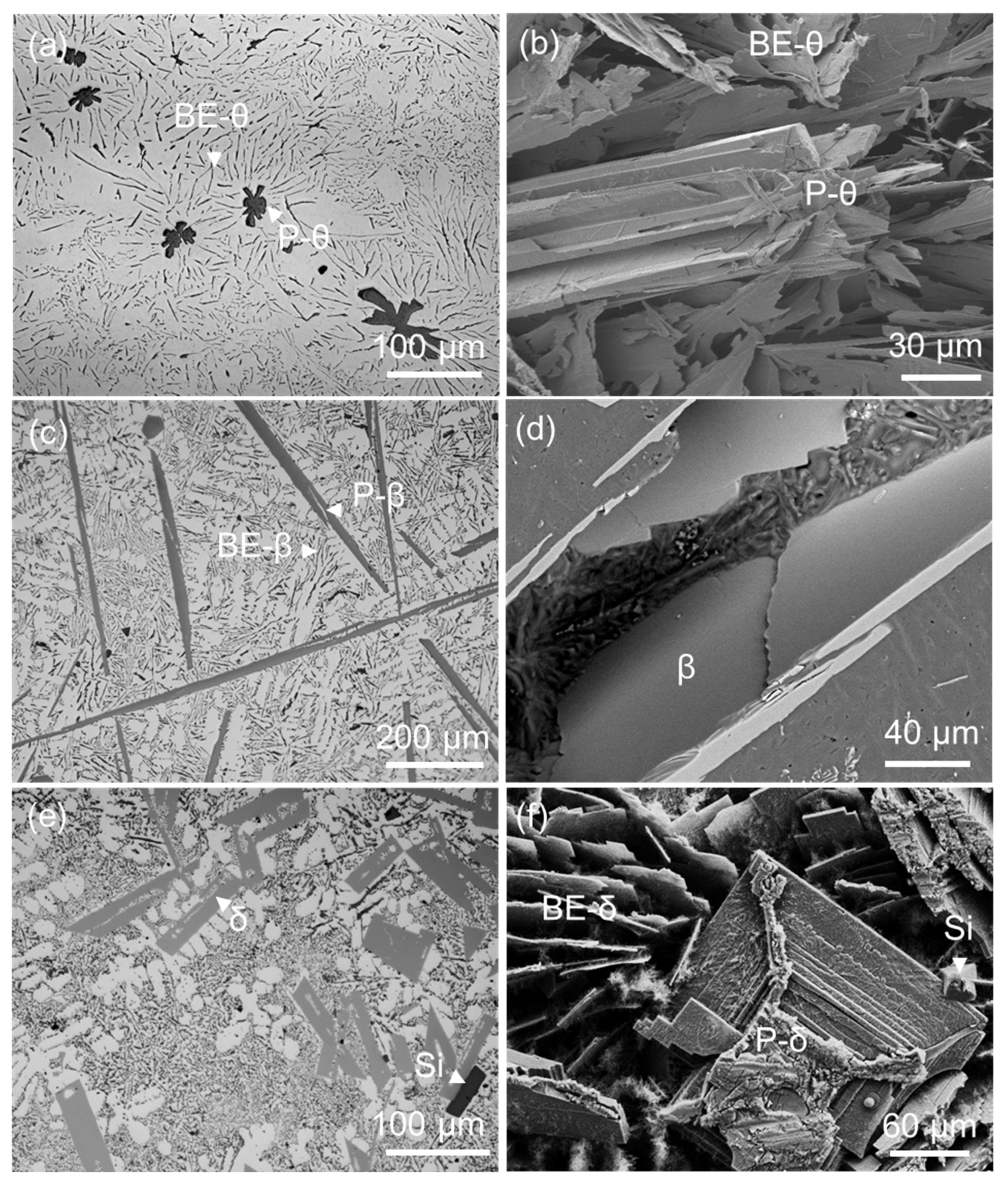
2.1. Morphology of FIMCs

Figure 1 shows the typical morphologies of the primary FIMCs in different Al alloys solidified with a cooling rate of 3.5 K/s. To fully understand the morphology of FIMCs, the 2D and 3D morphologies must be examined together. The θ-Al13Fe4, β-Al5FeSi and δ-Al4FeSi2 are all reported as plate-like. The morphology, composition and crystallographic of these three FIMCs are compared in Figure 1 and Figure 3 and Table 3 and Table 4. The differences between them are discussed here.
Figure 1a,b shows that the primary θ-Al13Fe4 phase has needle-like morphology with star-shaped cross-section in Al-3Fe binary alloy. Figure 1b in 3D confirms that the primary star-like θ at the cross-section is needle-like and the eutectic-θ is plate-like in this alloy. The needle-like eutectic-θ can also be observed in the same sample [80]. The star morphology of θ-Al13Fe4 is due to the twinning, which can be up to tenfold [24,25]. When the θ-Al13Fe4 is formed in Al-Fe-Si alloys (Figure 2c), Si dopes into the θ-Al13Fe4 phase and results in a change in composition (Table 3) and lattice parameters (Table 4) correspondingly, also accompanied with the slight change in the morphology of θ-Al13Fe4, which will be discussed in Section 2.2. It is hard to observe the tenfold twinning in the θ-Al13Fe4 formed in Al-4Fe-4Si alloys compared to the θ-Al13Fe4 that formed in the binary Al-Fe alloys. Up to sixfold twinning of θ-Al13Fe4 has been observed in Al-4Si-4Fe alloy solidified at 3.5 K/s. The composition of θ formed in different Al alloys are listed in Table 3. It shows that Si can incorporate into the θ phase at impurity concentration level, and the concentration increased with the Si content in the Al alloys. The concentration limit of Si in θ is up to 2.7 at.% by experimental observation [80], which is much lower than that of the DFT calculation (maximum being 4.9 at.%) [81]. When viewed along 2 ¯ 01 zone direction, the θ-Al13Fe4 is faceted on {010} planes, as shown in Figure 3a.
Compared to the other FIMCs, the morphology of β-Al5FeSi shows relatively less variation. Figure 1c,d shows that the β-Al5FeSi has a long and thin plate-like morphology in both the primary and eutectic structures. It is faceted on {002} when viewed along the [110] zone direction, as shown in Figure 3c. Some default features can easily be observed [67]. Figure 1d shows the primary β-Al5FeSi in a porosity (without etching), indicating a large-thin-plate morphology. The β-Al5FeSi plate is usually thin but coarse (Figure 1d and Figure 6c). Therefore, it is difficult to get its completely 3D morphology through deep etching. The other methods, such as computed tomography (CT) X-ray, can be applied but with high cost on time. It can be identified by scanning electron microscopy with energy-dispersive spectroscopy (SEM-EDS). For example, the major difference between the plate-like θ and β is the Si concentration in them. The θ phase has very low Si content (up to 2.7 at.% from experimental) compared to 17.3 at.% Si in β (Table 3), and usually shows twinning features.
Among these FIMCs, the δ-Al4FeSi2 is rarely reported in the literature, probably because it is considered a metastable phase. However, this FIMC is easily formed and mixed with β-Al5FeSi, especially in Al alloys with high Si contents. Figure 1e shows the brighter δ-Al4FeSi2 particles mixed with the primary Si (darker) in Al-16Si-3Fe alloy solidified at 3.5 K/s. The δ-Al4FeSi2 is much shorter and thicker than β-Al5FeSi plates, possibly due to the smaller a/c ratio of its lattice parameters in its crystal structure, as shown in Table 1. The 3D morphology of the δ plates are normally double plates with spiral growth trace, as shown in Figure 1f. This is different from the β and had never been reported in the literature. Moreover, the compositions of β and δ given in Table 3 revealed that the Si content in δ is much higher than that in β, with the content being as high as 30.6 at.% Si in the primary δ phase in Al-16Si-3Fe alloy. According to the measured compositions, the atomic ratio of Fe and Si is about 1:2, which corresponds to the chemical formula of δ-Al4FeSi2. The Si concentration in β is much lower than that in δ, which is 16–18 at.%, and the Fe and Si atomic ratio in β is about 1:1 according to the measured compositions. It also showed that the compositions of β and δ in different structures or different alloys have a smaller variation than that of α. As shown in Figure 3d, β is faceted on {002} when viewed along the [110] zone direction.
Figure 1. Primary FIMCs have plate-like morphology but with different morphological features. (a) optical microscope (OM), and (b) SEM-backscatter electron detector (BSD) of the rod-like θ-Al13Fe4 in Al-3Fe alloy with a star-like cross-section [80]; (c) OM, and (d) SEM-BSD of plate-like β-Al5FeSi in Al-12Si-0.6Mn-2.8Fe alloy; (e) OM, and (f) SEM-BSD of short plate δ-Al4FeSi2 in Al-16Si-3Fe alloy. All alloys were cast at 3.5 K/s. Note: in the figures above, P means primary; BE means binary eutectic.
Metals 12 01677 g001
Figure 2. Same type of FIMCs have completely different morphologies when formed at different stages of solidification. (a) OM image, and (b) SEM-BSD image showing that the α-Al15(Fe,Mn)3Si2 has a compacted morphology as primary phase but Chinese script morphology in binary eutectic structure in Al-5Mg-2Si-0.7Mn-1.3Fe alloy [31]; (c,d) SEM-BSD images of α’-Al8Fe2Si showing compacted morphology as primary phase but Chinese script morphology in eutectic structure in Al-4Fe-4Si alloy; (e,f) SEM-BSD images of η-Al6(Fe, Mn) in Al-2Mn-1Fe with Al-Ti-B grain refiner addition [82] showing the hollow-needle-like morphology. All alloys were cast at 3.5 K/s.
Metals 12 01677 g002
Figure 2a,b shows the typical microstructures of Al-5Mg-2Si-0.7Mn-1.3Fe alloy cast at 3.5 K/s. The compacted α-Al15(Fe,Mn)3Si2 particle is connected to the same surrounding intermetallic compound with Chinese script morphology, which was identified as primary and binary eutectic α phase, respectively (see Figure 5 later). The primary α (P-α) phase have different shapes, as shown in Figure 6a, which is due to its {110} faceted nature, as shown in Figure 3e [31]. The α-Al15(Fe, Mn)3Si2 is normally reported as compact morphology when its size is relatively small, e.g., up to a few tens of micrometres, as shown in Figure 2a and Figure 6a. However, when the α phase grows to large particles (larger than hundred micrometres) under certain conditions, e.g., in high alloy content (Fe, Si, Mn) Al alloys, it becomes not compact any more. One example is shown in Figure 8a later.
Table 3. The composition of different types of FIMCs.
AlloysFIMCsat.%Technique
AlFeMnSi
Al-3Fe (HP Al)θ-Al13Fe483.5 ± 0.416.5 ± 0.1--SEM [80]
Al-1Fe (CP Al)P-θ-Al13Fe4 80.8 ± 0.418.9 ± 0.10.00.3 ± 0.0TEM [80]
Al-4Fe-4SiP- θ-Al13Fe476.3 ± 0.620.6 ± 0.50.4 ± 0.052.7 ± 0.2TEM [80]
Al-4Fe-4SiPT-α’-Al8Fe2Si74.4 ± 0.315.3 ± 0.1-10.4 ± 0.1TEM [80]
Al-4Fe-4SiPT-β-Al5FeSi69.2 ± 0.313.8 ± 0.1-16.9 ± 0.1TEM [80]
Al-2Fe-8SiP-β-Al5FeSi68.0 ± 0.414.8 ± 0.1-17.3 ± 0.1SEM
Al-5Mg-2Si-0.7Mn-1.3Fe (0.01 K/s)P-θ-Al13Fe477.5 ± 0.416.2 ± 0.21.9 ± 0.12.0 ± 0.1TEM
Al-5Mg-2Si-0.7Mn-1.1Fe (0.01 K/s)P-α-Al15(Fe, Mn)3Si274.3 ± 0.413.7 ± 0.22.1 ± 0.17.7 ± 0.1TEM
Al-5Mg-2Si-0.7Mn-1.1Fe (3.5 K/s)P-α-Al15(Fe, Mn)3Si275.9 ± 0.511.2 ± 0.27.4 ± 0.15.5 ± 0.1SEM [31]
Al-5Mg-2Si-0.7Mn-1.1Fe (3.5 K/s)BE-α-Al15(Fe, Mn)3Si278.8 ± 0.59.0 ± 0.25.6 ± 0.16.6 ± 0.1SEM
Al-5Mg-2Si-0.7Mn-1.1Fe (3.5 K/s)TE-α-Al15(Fe, Mn)3Si285.1 ± 0.512.9 ± 0.20.8 ± 0.11.2 ± 0.1SEM
Al-16Si-3FeP-δ-Al4FeSi253.7 ± 0.515.7 ± 0.2-30.6 ± 0.2SEM
Al-2Mn-1FeP-η-Al6(Fe, Mn)84.5 ± 0.54.9 ± 0.210.5 ± 0.3-SEM
Al-2Mn-1FeBE-η-Al6(Fe, Mn)87.6 ± 0.58.3 ± 0.24.1 ± 0.3-SEM
Al-1.5Fe-0.7Mn-0MgP-η-Al6(Fe, Mn)88.9 ± 0.39.0 ± 0.42.3 ± 0.2-TEM [83]
Al-1.5Fe-0.7Mn-1MgP-η-Al6(Fe, Mn)88.8 ± 0.311.1 ± 0.42.6 ± 0.08-TEM [83]
Al-1.5Fe-0.7Mn-3MgP-η-Al6(Fe, Mn)88.8 ± 0.28.2 ± 0.153.0 ± 0.06-TEM [83]
Note: in the table above, TE means Ternary eutectic, and PT means phase transformed.
Table 4. Measured crystal lattice parameter of FIMC phases.
AlloysCrystalsa(Å)b(Å)c(Å)α(º)β(º)γ(º)Technique
Al-3Fe (HP Al) (0.01 K/s)θ-Al13Fe4 (0at.%Si)15.4824
(3)
8.08146
(15)
12.4689
(3)
90107.689
(2)
90SCXC [80]
Al-1Fe (CP Al) (0.01 K/s)θ-Al13Fe4 (0.3at.%Si)15.447
(4)
8.0567
(10)
12.429
(2)
90107.83
(2)
90SCXC [80]
Al-4Fe-4Si
(0.01 K/s)
θ-Al13Fe4 (2.4at.% Si)15.4239
(11)
8.0521
(5)
12.4040
(8)
90107.649
(7)
90SCXC [80]
Al-5Mg-2Si-0.7Mn-1.3Fe (0.01 K/s)α-Al15(Fe, Mn)3Si22.60804
(8)
12.60804
(8)
12.60804
(8)
909090SCXC
Al-4Si-4Fe (3.5 K/s)α’-Al8Fe2Si12.1312.1326.689090120TEM [80]
Al-4Si-4Fe (3.5 K/s)β-Al5FeSi6.166.1820.9790-90TEM [80]
Al-5Mg-2Si-0.7Mn-1.3Fe (3.5 K/s)θ-Al13Fe415.864-12.571---TEM [66]
Al-5Mg-2Si-0.7Mn-1.1Fe (3.5 K/s)α-Al15(Fe, Mn)3Si2(P)12.7012.7012.70909090TEM [31]
Al-5Mg-2Si-0.7Mn-1.1Fe (3.5 K/s)α-Al15(Fe, Mn)3Si2(BE)12.5812.5812.58909090TEM [31]
Al-5Mg-2Si-0.7Mn-1.1Fe (3.5 K/s)α-Al15(Fe, Mn)3Si2(TE)12.8312.8312.83909090TEM [31]
Al-1.5Fe-0.7Mn-0Mgη-Al6(Fe, Mn)7.576.638.37---TEM [83]
Al-Fe-Mn-1Mgη-Al6(Fe, Mn)7.366.478.65---TEM [83]
Al-Fe-Mn-3Mgη-Al6(Fe, Mn)7.286.548.57---TEM [83]
Note: SCXC: single-crystal X-ray crystallography.
Figure 3. High-resolution transmission electron microscopy (HRTEM) images showing the faceted planes of (a) θ-Al13Fe4 with (010) facet in Al-1.0Fe binary alloy cast from 720 °C [80]; and (b) η-Al6(Fe,Mn), (110) faceted when viewed along the [110] zone direction in Al-2Mn-1Fe cast from 720 °C [83]; (c) β-Al5FeSi with (002) facet in Al-12Si-0.6Mn-2.8Fe alloy, cast from 700 °C; (d) δ-Al4FeSi2 with (002) facet in Al-16Si-5Fe alloy cast from 720 °C; (e) α-Al15(Fe,Mn)3Si2 with (110) facet in Al-5Mg-2Si-0.7Mn-1.3Fe alloy cast from 720 °C [31]; and (f) α’-Al8Fe2Si with (100) faceted in Al-4Fe-4Si alloy cast from 760 °C. All alloys were cast at 3.5 K/s.
Metals 12 01677 g003
Figure 2c, d shows the primary α’-Al8Fe2Si particles mixed with the primary θ in Al-4Si-4Fe alloy solidified at 3.5 K/s. The α’ particles are compact similar to the α-Al15(Fe,Mn)3Si2 phase, and some of them are hexagonal. The measured composition of α and α’ are close, as shown in Table 3, but α’ has slightly higher Si content than that of α. As shown in Figure 3f, α’ is faceted on {100} when viewed along the [21] zone direction. The crystal structure of α and α’ are very complicated. There are 138 atoms in one-unit cell of the α phase, and 238.288 atoms in one-unit cell of the α’ phase [30,34]. The calculation for structural modification (e.g., alloy elements incorporation) is difficult due to the difficulties of building up the accurate crystal model especially for the shared atomic sites. The relationship between these two compounds and the formation mechanism are unclear also. Further research is required.
Figure 2e,f shows the η-Al6(Fe, Mn) phase with hollow needle-like morphology as primary phase. It is reported [83] that the morphology of η-Al6(Fe, Mn) phase is Chinese script when formed in eutectic structures, similar to that of α-Al15(Fe, Mn)3Si2 in eutectic structure. The η is (110) faceted when viewed along the [110] zone direction (Figure 3b) [83]. Moreover, the composition shown in Table 3 revealed that no Si is in the η-Al6(Fe, Mn) was detected. This is a very important feature to distinguish η-Al6(Fe, Mn) phase from the other types of FIMCs.
The terminated planes of FIMCs are not always faceted, which depends on the growth rate. The identified faceted planes can be observed non-faceted or containing some growth steps.

2.2. Composition and Crystallographic Variation of FIMCs

To understand the typical morphology of these multiple types of FIMCs in cast Al alloys, their crystallographic characteristics were investigated with SEM, TEM and X-ray analysis, as shown in Table 3 and Table 4. The measured lattice parameters of FIMCs in Table 4 were compared with the data from the other literature sources shown in Table 1. It can be seen that these FIMCs have very complicated crystal structures. The variable composition affects the corresponding lattice parameters, which makes their crystal structure more difficult to be understood. The information in Table 3 and Table 4 were investigated, which revealed the following important facts.
Firstly, the composition of FIMCs is closely related to the formation conditions, such as alloy composition. A large variation in Si concentration in the θ and α phases formed under different conditions was observed. For example, when θ was formed in Al-3Fe alloy prepared from high-purity Al (HP Al) (99.99 wt.%), no Si was detected in θ; Si was detected in θ when the commercial purity Al (CP Al) (containing < 0.04 wt.% Si) was used to prepare Al-3Fe alloy. The Si concentration in θ increases with the increasing Si content in Al alloys until reaching a maximum solubility. The maximum Si concentration in θ was experimentally measured as 2.7 at.% in θ in an Al-4Fe-4Si alloy, which is much lower than the 4.9 at.% calculated by DFT [81]. As reported in the literature, Si atoms can substitute some Al sites with low formation energy [81]. The effect of composition changes on the lattice parameters indicates that the lattice parameters a, b and c decrease slightly with the increasing Si concentration in θ, which agrees with the previous calculation results [81].
Secondly, the solubility of Si in different FIMCs is different and there is a sequence. In the six types of FIMCs concerned in this overview, except η, which does not contain Si, the other the types of FIMCs can accommodate some Si in their crystal structure. The basic structure of θ phase is reported to be θ-Al13Fe4. Si has no independent atomic site with 100% occupancy in θ, but can be incorporated on some of the Al sites [81]. The experimentally measured maximum Si solubility in θ is 2.7 at.%. The built crystal models for α, α’ and β in the literature [20,30,34] show that the Si atoms in these crystals can share all the Al sites with different occupancies. It is more complicated for the α phase since Mn atoms can share some Fe sites and some Al sites. The δ phase was reported [35] to have independent Si site rather than shared site with Al atoms. The experimentally measured Si solubility in these FIMCs reveals a sequence that was summarized as :   0 = C η S i < C θ S i < C α S i < C α S i < C β S i < C δ S i . The composition variation of FIMCs and this Si solubility sequence of FIMCs contributed to the phase transformation between two different types of FIMCs, which will be discussed in Section 3.
Thirdly, the compositions of FIMCs changes significantly with the availability of the solute atoms. For example, the Mn concentration of the α phase formed at different stages of solidification varies significantly, being 7.4 at.% in primary α, 5.6 at.% in binary eutectic α and 0.8 at.% in ternary eutectic α. This is due to the difference in availability of alloying elements at different solidification stages. The corresponding concentration changes of Fe and Si are 11.2→9→12.9 at.% and 5.5→6.6→1.2 at.%, respectively. The built crystal model of α showed [30] that the Mn can occupy both the Al sites and partial Fe sites, but the Si only shares the Al sites. These results suggest that the FIMCs are not strictly stoichiometric compounds, but have some solubility range for alloying elements.

2.3. The Same Intermetallic Compounds with Different Morphologies

The morphology of some of the FIMCs are completely different when they are present in different structures. For example, the α-Al15(Fe,Mn)3Si2 phase have a compact morphology as the primary phase but Chinese script in binary eutectic structures. There are controversies about the Chinese script α-Al15(Fe,Mn)3Si2, in which it is argued that the Chinese script α is formed as the primary phase but growth from the compacted primary α. New evidence in recent work clearly shows that the Chinese script α belongs to the eutectic structures that nucleated on the primary α compound. Figure 4 provides the evidence of electron backscatter diffraction (EBSD) mapping, demonstrating that the Chinese script α is nucleated on (or grows from) the primary α as the leading phase for the formation of TE binary eutectic structures. The α phase in most eutectic structures has a Chinese script morphology. However, the α phase in some eutectic structures can have the same compacted morphology as the primary α. Figure 5 shows the compacted primary α (Figure 5a), the Chinese script binary eutectic α (BE-α) (Figure 5b) and the ternary eutectic (TE-α) with a compact morphology. Figure 5c shows that when the Al-2Si-0.7Mn-1.3Fe alloy solidified at a very slow cooling rate (0.01 K/s), compact TE-α was nucleated on (or grow from) the tip of the BE- α. The difference in the morphology of FIMCs between primary and eutectic FIMCs is possibly caused by the difference in the formation conditions such as surrounding phases, cooling rate, etc.
The characteristics of morphology, composition and crystallography of different types of FIMCs were investigated and compared by applying OM, SEM and/or XRD, TEM to understand the relationship between different types of FIMCs. To further understand the competition between different FIMCs for nucleation or phase transformation, further investigation on the formation, composition and crystallographic variation of α and α’ are required.

3. Competition of Nucleation and Phase Formation of FIMCs

The phase competition between FIMCs is complicated and difficult to control. The nucleation undercoolings of these intermetallic compounds are reported to be a few tens of Kelvin (K) [84], which reflects the difficulty in nucleation of these compounds. The equilibrium phase diagram is not a reliable tool to predict the microstructure correctly, as formation of FIMCs may be largely controlled by transformation kinetics rather than thermodynamics. In this section, a few case studies will be presented to demonstrate the competition for nucleation of FIMCs, which contributed to the final complicated phase competition.

3.1. Phase Competition of P-FIMCs and Its Effect on the Solidification Sequence

According to the calculated phase diagram, Figure 6, the Al-11.7Si-0.6Mn-2.8Fe alloy will solidify with α-Al15(Fe, Mn)3Si2 as the primary phase. Phase competition between α and β in Al-11.7Si-0.6Mn-2.8Fe alloys was investigated and the results are shown in Figure 7.
Figure 7a shows the microstructure of Al-11.7Si-0.6Mn-2.8Fe alloy solidified at 3.5 K/s. Without grain refiner addition, there are two different types of primary FIMCs, α-Al15(Fe, Mn)3Si2 (major) and β-Al5FeSi (minor). The FIMCs in eutectic structures are mainly plate-like β, as shown in Figure 7b. The primary α particles in this sample are in the size range of 50–150 μm and have a petaled flower morphology with hollows, which are much larger in size than the α particles shown in Figure 5a. It indicates that the growth of P-α leads to a hollowed morphology rather than the Chinese script morphology.
When 1000 ppm grain refiner (Al-Ti-B) was added, the primary FIMCs in Al-11.7Si-0.6Mn-2.8Fe alloy changes to major long-plate β and a few hollowed α, as shown in Figure 7c. This grain refiner contains TiB2 particles with interfacial segregation of Fe and Si. Correspondingly, the FIMCs in eutectic structures change from plate-like β to Chinese script α, as shown in Figure 7d. The difference in eutectic structures in these two samples without and with TiB2 addition is due to the composition variation in the remaining liquid after the formation of different primary FIMCs. This result demonstrated that the non-equilibrium β can be nucleated and selected as the primary phase due to the enhanced heterogenous nucleation of β on modified TiB2 particles. It demonstrates that the phase competition of FIMCs can be controlled at the nucleation stage for the primary FIMCs by changing the potency of the nucleation substrate.

3.2. Nucleation Competition between FIMCs

In some case, although the non-equilibrium FIMCs can be selected after winning the nucleation competition, they become unstable after their formation in the liquid and finally transform into the equilibrium FIMCs before the eutectic formation happens. In other words, the equilibrium FIMCs are growing on the previously formed non-equilibrium FIMCs after complete or partial phase transformation rather than nucleated on the nucleation substrates. It was reported that the Al-5Mg-2Si-0.6Mn-1.3Fe alloys has a large temperature range (44 K) for the formation of primary α-Al15(Fe, Mn)3Si2 [31]. When this alloy solidifies at a slow cooling rate of 0.01 K/s, the other types of FIMC with irregular morphology was observed in the centre of the compacted primary α particles (equilibrium) (Figure 8). The P-α particles settled down and collected at the bottom of the crucible at such slow cooling rate. These P-α particles were observed with X-ray CT. It shows that each P-α particle contains a brighter centre plate-like particle. These two different types of FIMCs were identified with EBSD mapping (Figure 9b). The further EBSD (Figure 9a,b) and TEM (Figure 9c) analysis showed that the outer of the compacted particle is α-Al15(Fe, Mn)3Si2 and the inner of the particle is θ-Al13Fe4. The HRTEM image in Figure 9c shows the interface between θ-Al13Fe4 and α-Al15(Fe, Mn)3Si2. There is a well-defined orientation relationship (OR) between θ-Al13Fe4 and α-Al15(Fe, Mn)3Si2: 2 ¯ 01 θ-Al13Fe4//2.3° 0 1 ¯ 1 α-Al15(Fe, Mn)3Si2, and [0 1 0] θ-Al13Fe4//[1 0 0] α-Al15(Fe, Mn)3Si2. (OR1)
This result demonstrates that the compacted primary α-Al15(Fe, Mn)3Si2 did not directly form through heterogeneous nucleation on some potent substrates, such as native oxides, but formed via a peritectic reaction: L + θ-Al13Fe4 → α-Al15(Fe, Mn)3Si2 + α-Al. The non-equilibrium θ was firstly nucleated and formed/selected as the PIMC instead. The selected non-equilibrium θ became unstable at a later solidification stage, and finally transformed into the equilibrium α.
It has been demonstrated that the phase competition among the FIMCs starts at the early stage of solidification. As reported [82], different types of Fe-intermetallic compounds require different nucleation undercoolings. The intermetallic with smaller nucleation undercooling can form firstly during the solidification process, which is called nucleation competition in this paper. The mechanism will be discussed in details in Section 3.3. When the non-equilibrium (NE) FIMC wins the nucleation competition, the solidification sequence will be changed correspondingly with the growth of the NE-FIMC. However, with the continuously solidification, the formed non-equilibrium FIMC becomes unstable in the remaining liquid and might transform into other types of more stable FIMCs.

3.3. The Mechanism of Nucleation Competition between FIMCs

The heterogeneous nucleation of FIMCs is complicated, which not only requires the potent nucleation substrates but also multiple alloy elements and specific crystal structure. Therefore, multiple factors need to be considered to understand the nucleation competition between different types of FIMCs. A simple sketch is shown in Figure 10 to illustrate the mechanism of nucleation competition between two types of FIMCs, A and B. The dotted lines in the figure show the liquids for A (TA) and B (TB). It is assumed that A is the equilibrium FIMC, and B is the non-equilibrium FIMC. A has the higher formation temperature (TA) but lower nucleation temperature (∆TnA). The NE-B has the lower formation temperature (TB) but higher nucleation temperature (∆TnB). The nucleation undercooling ∆Tn can be calculated as (T-Tn). Therefore, in this case, ∆TnB is smaller than ∆TnA. During the solidification process, nucleation of the NE-B happens first. As has been presented elsewhere [85], the general rule governing nucleation competition is that the phase with smallest nucleation undercooling will nucleate first, followed by phases with progressively larger nucleation undercooling.

4. Phase Transformation between FIMCs

The previous section has shown a case for phase transformation between the non-equilibrium θ and the equilibrium α phase (Figure 9). Investigation on the phase transformation between different types of FIMCs is not only helpful to understand the relationship between FIMCs, but also useful to understand the nucleation competition between them. It is found that the θ-Al13Fe4 is often to form as non-equilibrium phase in Al-Si alloys. This NE-θ then transformed into the other types of FIMCs later such as α’, α, β or δ phases. The phase transformation between FIMCs was investigated based on the composition variation and crystal structure transition. It is found that the NE-θ can transform into the other FIMCs with one step or multi-step transformation, and with or without intermediate intermetallic compounds. The phase transformation is mainly controlled by elemental diffusion, especially Si, and follows a Si concentration sequence. A few cases will be discussed in this section.

4.1. Multi-Step Transformation from θ to α’, β then δ

The calculated solidification path with Padant software under the Scheil model is shown in Figure 11, which suggests that under equilibrium condition this alloy should solidify first with primary Si phase followed by (δ-Al4FeSi2 + Si) and (β-Al5FeSi + Si) eutectics. Multiple-step phase transformation from θ to α’, then β, and finally δ was observed in Al-20Si-0.7Fe alloy solidified at a slow cooling rate (0.01 K/s), as shown in Figure 12 and Figure 13 [67]. The primary θ phase was formed in an Al-20Si-0.7Fe alloy at a slow cooling rate, 0.01 K/s, as shown in Figure 12a. However, solidification experiments have confirmed that the real solidification process does not follow this path. The non-equilibrium θ (Figure 12a) is the primary phase with a coarse platelet morphology and shows clear signs for phase transformation (Figure 12b).
The SEM observation, Figure 12b, shows that the parent θ-Al13Fe4 phase is associated with the β-Al5FeSi phase and a two-phase structure that contains α’-Al8Fe2Si + α-Al. All the phases were identified with EBSD (Figure 12c) and TEM (Figure 13) analysis. The results show that the θ-Al13Fe4 phase (monoclinic) formed initially and transformed into an intermediate α’-Al8Fe2Si (complex hexagonal) and nanoscale α-Al via a quasi-peritectoid reaction (Figure 11b). Subsequently, the intermediate α’-Al8Fe2Si transformed into β-Al5FeSi (monoclinic). After heat treatment (530 °C for 30 min), the transformed β-Al5FeSi phase transformed again into δ-Al4FeSi2 (tetragonal) as shown in Figure 12d. The SEM-EDXs results shown in Figure 12e indicated the increased Si content in from θ to β then δ. Variations in composition and lattice parameters of these FIMCs was also determined by TEM, which shows that the phase transformation among the FIMCs starts from the FIMC with a lower Si content and progresses to the FIMCs with higher Si contents. The transformation sequence is following the Si concentration in FIMCs in the order of C θ S i < C α S i < C β S i < C δ S i . Multi-step phase transformations between FIMCs in high-Si Al alloys were observed during solidification process.
The phase transformation sequence can be described as L→ θ-Al13Fe4; then L+ θ-Al13Fe4 → α’-Al8Fe2Si + α-Al; then L+ α’-Al8Fe2Si → β-Al5FeSi + α-Al; and finally, L+ β-Al5FeSi→ δ-Al4FeSi2 + α-Al. The phase transformation process is controlled by diffusion of constituent elements Fe and Si, especially Si in the FIMCs. The α’-Al8Fe2Si forms as the intermediate FIMC during the phase transformation from θ-Al13Fe4 with a low Si content to higher Si containing β-Al5FeSi. Nanoscale α-Al particles were observed within the FIMCs to accommodate the changes in composition of the FIMCs, allowing a shorter diffusion path. The interfaces between each of these FIMCs were examined to determine the orientation relationships (see Figure 13). Defined orientation relationships were observed at the interfaces of θ-Al13Fe4//α’-Al8Fe2Si, α’-Al8Fe2Si//β-Al5FeSi, and β-Al5FeSi//δ-Al4FeSi2. The ORs are:
( 1 ¯ 0 3) θ-Al13Fe4//(1 1 ¯ 1) α’-Al8Fe2Si and [ 1 ¯   3 ¯   4 ¯ ] θ-Al13Fe4//[ 3 ¯ 2 1 ¯ ] -Al8Fe2Si(OR2)
(0 0 2) β-Al5FeSi//10.2°(1 0 0) α’-Al8Fe2Si, [0 1 0] β-Al5FeSi//[1 2 3] α’-Al8Fe2Si,(OR3)
And (0 0 2) [1 1 0] β-Al5FeSi//(0 0 2) [1 1 0] δ-Al4FeSi2(OR4)
A few pairs of defined orientation relationships containing the crystallographic information about the phase transition between FIMCs were experimentally observed for the first time. Further investigation is under way to study the relationship between the composition variation and the crystallographic transition between FIMCs.

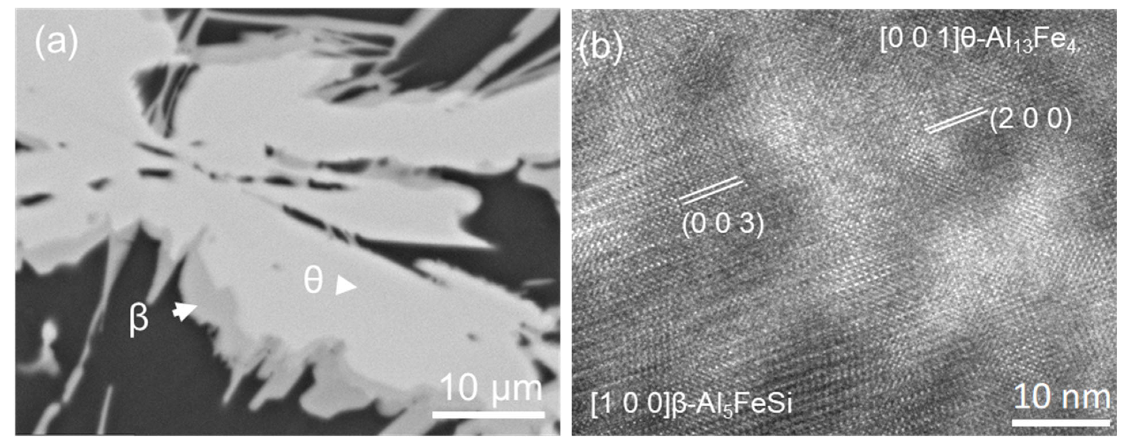
4.2. One Step Phase Transformation from θ to β

A case of phase transformation directly from θ-Al13Fe4 to β-Al5FeSi was found to involve no intermediate IMCs, as shown in Figure 14. Figure 14a shows transformation from θ to β in Al-4Fe-4Si alloy solidified at 3.5 K/s. The HRTEM image in Figure 14b shows the interface between β-Al5FeSi and θ-Al13Fe4, revealing an orientation relationship between these two FIMCs. The orientation relationship between θ-Al13Fe4 and β-Al5FeSi was identified as:
(200) θ-Al13Fe4//(003) β-Al5FeSi, and [1] θ-Al13Fe4//[100] β-Al5FeSi(OR5)
Si as impurity or solute in Al alloys is easily doped into the θ-Al13Fe4 structure, which causes not only variation in compositions but also modification of lattice parameters, and in some circumstances, even crystal structure. Controlled by Si diffusion in Al-Si-Fe alloys, different types of phase transformation happen between θ and the other FIMCs. Based on this understanding, the phase transition between FIMCs have been studied, e.g., the intrinsic defects and Si solution in θ-Al13Fe4 and the structural investigation with DFT simulations [81,86,87], and the stability of FIMCs from thermodynamics assessment [88].
Previous work revealed that the phase competition between various FIMCs in Al alloys is due to the competition in both nucleation and phase transformation in the solid state. Once the non-equilibrium FIMCs were nucleated, the composition in the remaining liquid was changed, which affects the final solidification microstructure. However, understanding of the crystallographic relationships between FIMCs and the structural transition mechanism is still very limited. Further work is required for developing effective control of the formation of FIMCs both during solidification and in the subsequent solid-state transformations.

5. Heterogeneous Nucleation and Refinement of FIMCs

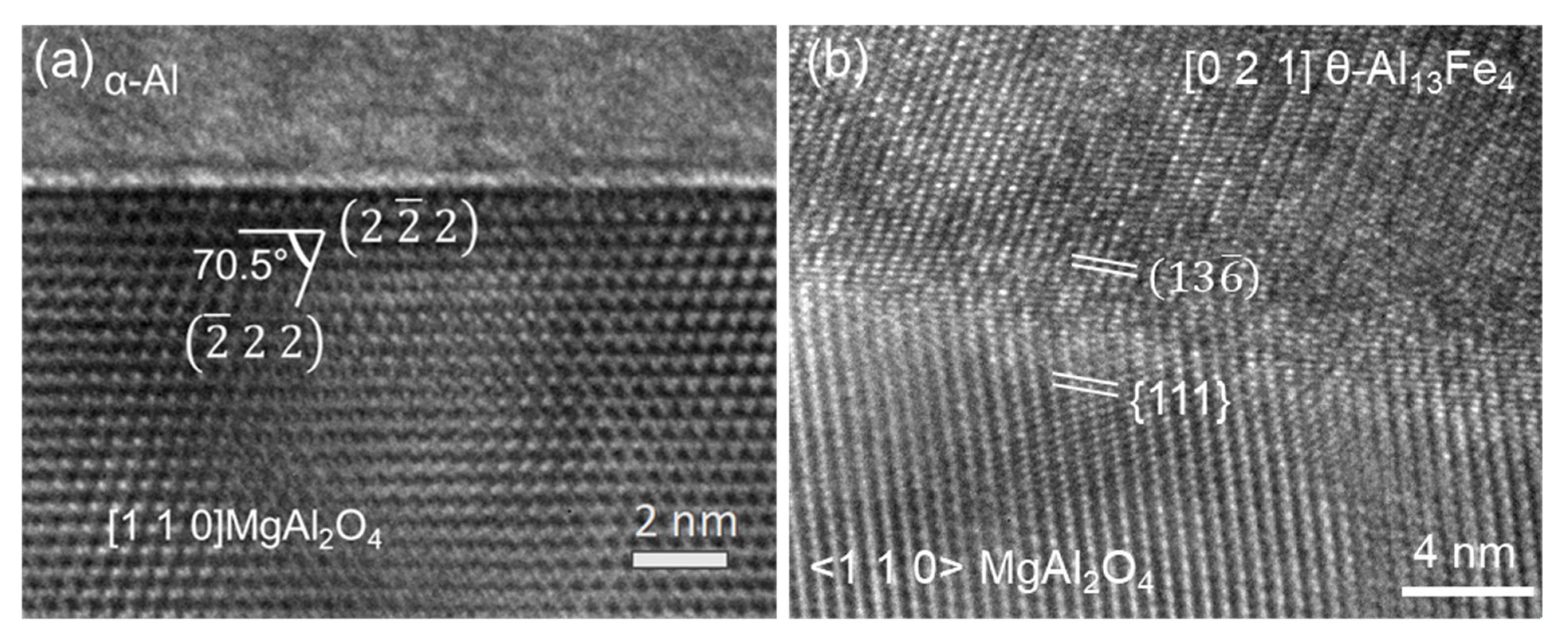
5.1. Heterogeneous Nucleation of FIMCs on Native Oxides

As already shown in Section 3, phase competition among FIMCs on the heterogeneous nucleation stage is critically important for the final microstructure of the cast Al alloys. Before any refining method is developed, it is necessary to understand heterogeneous nucleation of FIMCs on the native oxides/inclusions (without grain refiner addition). For Al alloys, different types of common inclusions can be generated in the melt during the casting, such as oxides (α-Al2O3, γ-Al2O3, MgAl2O4, and MgO etc.), carbides, borides, nitrides, chlorides, and fluorides. The major oxides are MgAl2O4 and/or MgO in Mg-containing Al alloys. The characteristics of the native MgAl2O4 in Al-3Fe-1Mg are shown in Figure 15. It shows that the size of MgAl2O4 varies from a few hundred nanometres to a few micrometres, depending on the synthetic processing conditions. The MgAl2O4 particles can be easily engulfed in the FIMC particles. The 3D morphology of MgAl2O4 in Al-3Fe-1Mg alloy was observed and is shown in Figure 15 b. TEM examination in Figure 16a confirms that the MgAl2O4 particles have face-centred cubic (fcc) crystal structure with lattice parameter a = 8.08 ± 0.005Å and are {1 1 1} faceted when viewed along its <1 1 0> zone direction, and the angles between two adjacent termination planes were measured to be 109.5 ± 0.4°or 70.5 ± 0.5°.
It has been shown in Section 3 that θ phase can be first nucleated as a non-equilibrium phase in some Al alloys without any grain refiner addition. Therefore, the nucleation of θ on the native oxides is investigated. The HRTEM image in Figure 16b provides the evidence of heterogeneous nucleation of θ on a native MgAl2O4 particle, by revealing an orientation relationship (OR) between the MgAl2O4 and θ-Al13Fe4:
2   2 ¯   2 MgAl2O4// 1   3   6 ¯ θ-Al13Fe4 and(OR5)
[1 1 0] MgAl2O4//3.4° [0 2 1] θ-Al13Fe4. [66]
It is the first time that the evidence of heterogeneous nucleation of any FIMC on substrates, especially on a native oxide, particle to be revealed. Two facts have been confirmed. Firstly, the θ-Al13Fe4 can nucleate on MgAl2O4 particles, and secondly, the phase competition between the FIMCs is due to the competition of heterogeneous nucleation among FIMCs in Al alloys.
Heterogeneous nucleation is dependent on the nucleation potency of the nucleation substrates [89], but the grain refinement is affected by many other factors [90,91,92,93]. Although clear evidence of the heterogeneous nucleation of θ on MgAl2O4 was observed, many questions remain unclear to fully understand the heterogeneous nucleation of FIMCs. For example, there are many different types of inoculants, such as MgO, Al2O3, AlN, MgAl2O4, which might co-exist in different Al alloys. Nucleation potency of different types of FIMCs is unclear. Moreover, the interfacial structural and compositional conditions of these native particles have rarely been investigated. Recent research indicated [94,95,96,97,98,99] that the interfacial conditions of particles such as TiB2 in the melt can be modified by segregation of alloy elements. Therefore, the surface of the native oxide particles will also be affected by the interfacial segregation of the alloy elements. Recent research [99] also shows that alloy elements tend to segregate on the surface of native oxides, and the nucleation potency of the oxide was thus changed correspondingly, which can be analysed from the orientation relationships between the solid and substrates. Further investigations are required to understand the effects of interfacial segregation of alloy elements on the structural and compositional templating of the nucleation substrates for heterogeneous nucleation of FIMCs.

5.2. Heterogeneous Nucleation on the Other IMCs and Refinement of FIMCs

Many approaches to grain refinement in Al alloys, such as thermal control, chemical methods, and mechanical methods, have been developed to enhance the properties of Al alloys [100,101]. Addition of alloying elements is one of the easiest ways to achieve grain refinement of cast alloys. Various alloy elements were applied in Al-Fe alloys for the purpose of modification and refinement of FIMCs [44,45,46,47,48,49,50,51,52,53,54,55,56,57]. It is known that Mn addition can modify the plate-like β phase to the compact α-Al15(Fe, Mn)3Si2 when the Fe/Mn content ratio is lower than 2. However, no obvious refinement of the FIMC was reported through the alloy element addition. Systematic work has been done to study the effects of alloy elements on heterogeneous nucleation of FIMCs. It was found that when 0.5 wt.% Zr was added to Al-4Fe alloy, both the primary θ and α-Al grains were greatly refined, as shown in Figure 17 and Figure 18 [88]. Figure 17 shows that the size of θ decreases from 125.2 ± 5.0 to 22.5 ± 0.9 μm, and its number density increased from 39.5 ± 2.4 mm 3 to 194.4 ± 32.5 mm 3 with 0.5 wt.% Zr addition in the Al-4Fe alloy. Meanwhile, the average size of α-Al grains decreases from 435.2 ± 40.8 μm to 63.1 ± 2.8 μm. It was observed that some of the previously formed Al3Zr particles were located inside the θ phases and α-Al grains, contributing to the grain refinement of both the θ and α-Al [102].
The experimental results show that the previously formed Al3Zr particles have a larger number density than that of θ, which suggests that the heterogeneous nucleation of Al3Zr on native oxides is much easier than that of θ. It demonstrated that the FIMCs can be grain refined by enhancing heterogeneous nucleation on the other types of intermetallic compounds. This is another approach to grain-refine the FIMCs. However, this method introduces the other types of compounds and increases alloy concentration, which needs to be carefully considered. Further work is required to study the effects of more types, the concentration of alloy elements and casting conditions, etc. on heterogeneous nucleation of FIMCs, and especially the effects of alloy elements on the nucleation potency of native oxides for the FIMCs.

5.3. Compositional Templating for Heterogeneous Nucleation and Refinement of FIMCs

The most widely used way to grain-refine alloys is by adding inoculants during the casting process. The mechanism of grain refinement with inoculants is to supply potent particles for heterogeneous nucleation [90,91,92,93]. Al-Ti-B grain refiners have a long history and have been proven to be effective in achieving grain refinement of Al alloys [103,104]. Therefore, TiB2 particles were chosen as the reference particles in our research. In addition, epitaxial nucleation provides an atomistic mechanism for heterogeneous nucleation via structural templating [89]. Based on structural templating, a three-layer mechanism for heterogeneous nucleation has been recently developed, in which heterogeneous nucleation completes within three atomic layers to create a 2D nucleus (a crystal plane of the solid) [105,106]. This three-layer nucleation mechanism has been validated by high resolution transmission electron microscopic (HRTEM) examination of TiB2/Al and TiB2/α-Al15(Fe, Mn)3Si2 interfaces in two different Al alloys [106]. Based on these advanced understandings, the refinement of FIMCs was reconsidered. Heterogeneous nucleation of IMCs is much more difficult than that of a pure metal or a solid solution. It requires not only the creation of a crystal structure but also the positioning of two or more types of elements in the lattice with specified compositions. Therefore, an approach to enhance heterogeneous nucleation of FIMCs by facilitating the compositional templating in addition to structural templating was developed. This approach is demonstrated in Figure 19 and Figure 20 and Table 5 [82].
Al-Ti-B master alloys with free Ti or free B were designed and produced. Alloy elements, such as Fe, Mn, Si, and Ni, were added to the melts to form a segregation layer on the TiB2 or AlB2 to provide the structural and compositional templating. The interfacial segregation and the new interfacial structures at the Al/TiB2 or Al/AlB2 interfaces were investigated and the nucleation potency for the IMCs estimated. The nucleation potency of TiB2 particles was changed by generating interfacial segregation. The experimental results show that the segregation of Fe at the TiB2 surface (TiB2(Fe)) can provide composition templating and hence enhance heterogeneous nucleation of α-Al15(Fe, Mn)3Si2, resulting in significant refinement of the intermetallic compound. Segregation of Mn at the TiB2 surface (TiB2(Mn)) can provide composition templating and hence enhance heterogeneous nucleation of η-Al6(Fe, Mn) resulting in significant grain refinement. The grain refinement results are summarized in Table 5. One of the examples is shown in Figure 19 and Figure 20 [82].
Figure 19 shows the Super-X EDS elemental mapping results for the TiB2 particles in Al-3.7Ti-1.5B-1Mn alloy. Mn segregation is clearly seen on the {10 1 ¯ 0} planes of TiB2. When this grain refiner containing the Mn-modified TiB2 particles was added into an Al-2Mn-1Fe alloy, the η-Al6(Fe, Mn) was refined considerably (see Figure 20a,b). The size of the cross-section of η-Al6(Fe, Mn) was reduced from 26.0 ± 2.1 μm to 9.5 ± 0.6 μm after 1000 ppm addition of the Al-3.7Ti-1.5B-1Mn grain refiner. The Mn-modified TiB2 particles were found to be engulfed in the η-Al6(Fe, Mn) particles (Figure 20c). Some of the TiB2 particles have a well-defined orientation relationship with η-Al6(Fe, Mn). See Figure 20:
( 2   0   0 ) η [ 0   2   1 ] η / / ( 0   0   0   1 ) TiB 2   1   1   2 ¯   0   TiB 2   (OR6)
The grain refinement results are summarised in Table 5. The interfacial segregation of different elements, such as Fe, Mn, and Si, on AlB2 or TiB2 particles [82] were investigated and confirmed on an aberration (Cs)-corrected FEI Titan 80–200 instrument equipped with Super-X energy-dispersive X-ray spectroscopy (Super-X EDS) system. These different types of Al-Ti-B master alloys containing modified AlB2 or TiB2 particles were added to different alloys shown in Table 5 to test their effect on refining both FIMCs and α-Al. It shows that the TiB2 particles with Fe and Si segregation (TiB2(Fe, Si)) are most effective. It can refine not only α and β FIMCs, but also the primary Si phase. TiB2(Fe, Si)) particles refined the α-Al15(Fe, Mn)3Si2 from 38.7 ± 6.8 μm to 11.1 ± 4.4 μm in Al-5Mg-2Si-0.7Mn-1.3Fe alloy, and refined β-Al5FeSi from 1178.4 ± 135 μm to 425.2 ± 61 μm in Al-12Si-0.7Mn-2.8Fe alloy. The primary Si phase was refined from 461 ± 51 μm to 39 ± 5.5 μm in Al-27Si alloy. The master alloy containing TiB2(Ni, Si)) particles can grain-refine α-Al in CP-Al to 184 ± 20 μm, which is similar to the effect of Al-5Ti-1B.
Further work is required to investigate the structural modification caused by the interfacial segregation and the assessment of the nucleation potency of modified particles for the FIMCs. Moreover, further studies are required to understand the interfacial segregation on native oxides at the same time, and the competition contribution of the heterogeneous nucleation for FIMCs between the native oxides and the added inoculants.

6. Challenges/Future Research

Current research has achieved some fundamental understandings on the heterogeneous nucleation, formation, and phase transformation mechanisms of Fe-intermetallic compounds in Al alloys. Some useful techniques have been developed to modify the nucleation substrates by providing the structural and compositional templating. However, there are a few more challenges that need further investigations to achieve the ideal microstructural control and refinement of FIMCs.
The first is the understanding of heterogeneous nucleation of the FIMCs in Al alloys on the native inoculants, especially oxide particles. Due to the complexity of heterogeneous nucleation, different types of FIMCs can be nucleated competitively, which leads to the subsequent solid-state phase transitions between different types of FIMCs. Moreover, the true nucleation sequence/solidification sequence could be covered up by the final solidification microstructure. For example, when θ phase was nucleated as non-equilibrium phase in Al-5Mg-2Si-0.7Mn-1.3Fe, phase transformation happened and completely covered by the α phase [66]. The final microstructure (Figure 2a) could mislead researchers to consider that the primary α phase actually formed from the phase transformation of θ is directly formed from the heterogeneous nucleation on the native oxides. Therefore, direct evidence for heterogeneous nucleation of FIMCs on neither oxides nor the external applied grain refiner particles is rarely reported.
The second is the understanding of the effect of the interfacial atomic arrangement on structural and compositional templating on the surface of potent nucleation substrates. The FIMCs are formed in multi-component alloys. Therefore, understanding of interactions between the nucleation substrates and the alloy elements is important to investigate the nucleation potency. There is plenty of evidence to show that alloy elements in the melt can modify the surface of particles by interfacial segregation. However, the types of alloy element, segregation concentration, and atomic arrangement at the liquid–substrate interface, and so on, still warrant further investigations. This is especially difficult for FIMCs due to the nature of multi-component alloys. The other difficulty arises from the nucleation competition between FIMCs on different nucleation substrates. At present, the competition for heterogeneous nucleation between multiple types of substrates is not clear. For example, when Al-Ti-B master alloys are added in Al melt, there is competition for heterogeneous nucleation on the exogenous TiB2 particles and the other native inoculants, such as Al2O3, MgO or MgAl2O4.
The third is the understanding of crystallographic relationships between different types of FIMCs. The phase transformation between FIMCs has been widely reported. In recent years, some research attention has been paid to investigation of the phase formation, crystal structure and microstructural evolution between FIMCs [67,82,83,97,107,108,109]. However, due to the complex crystal structure of each FIMC and the composition-lattice parameter variations, experimental research is very difficult but necessary to investigate the phase transition between these FIMCs by applying experiments and computer calculations. The structural transition between FIMCs helps us to understand not only the phase transformation happening in solid states but also the nucleation competition during the solidification process. Computer calculation methods such as DFT, molecular dynamic (MD) simulation, etc. are required, especially for investigation of the phase transitions between different types of FIMCs.

7. Summary

In this paper, a concise overview of the recent fundamental research on the formation of Fe-containing intermetallic compounds (FIMCs) in Al alloys was provided. Some good progress has been made, particularly on understanding the heterogeneous nucleation of FIMCs and the mechanism of phase transition between FIMCs. This is summarized as follows:
  • FIMCs in Al alloys are not strictly stoichiometric compounds and hence can accommodate certain levels of alloying elements in their crystal lattice without changing their crystal structure, although this may cause some changes in their lattice parameters. For instance, Si content in the θ phase increases with increasing Si content in Al alloys. The maximum Si concentration in θ is experimentally measured to be 2.7 at.%. The lattice parameters of θ decreased with the increasing Si concentration in θ.
  • The composition of FIMCs changes significantly to adjust the consuming rate of different alloy elements at different stages of solidification. For instance, Mn concentration in α-Al15(Fe, Mn)3Si2 reduced from 7.4 at.% in the primary α, to 5.6 at.% in the binary eutectic α, and then 0.8 at.% in the ternary eutectic α, without changing the crystal structure. In addition, the solubility of Si in FIMCs has a sequence of 0 = C η S i < C θ S i < C α S i < C α S i < C β S i < C δ S i , which contributed to the phase transformation between different types of FIMCs.
  • The FIMCs that have a broad plate-like morphology, such as θ, β and δ, may have different morphological features. The θ has up to tenfold twins, which can grow into star-like morphology on its cross-section; the β is thin but coarse; the branches on β are less observed; the δ is shorter than β and grows with spiral traces. The terminating surface planes of the relevant FIMCs were identified. The θ is {010} faceted. The β and δ are both {002} faceted. The α and η are {110} faceted. The α’ is {100} faceted.
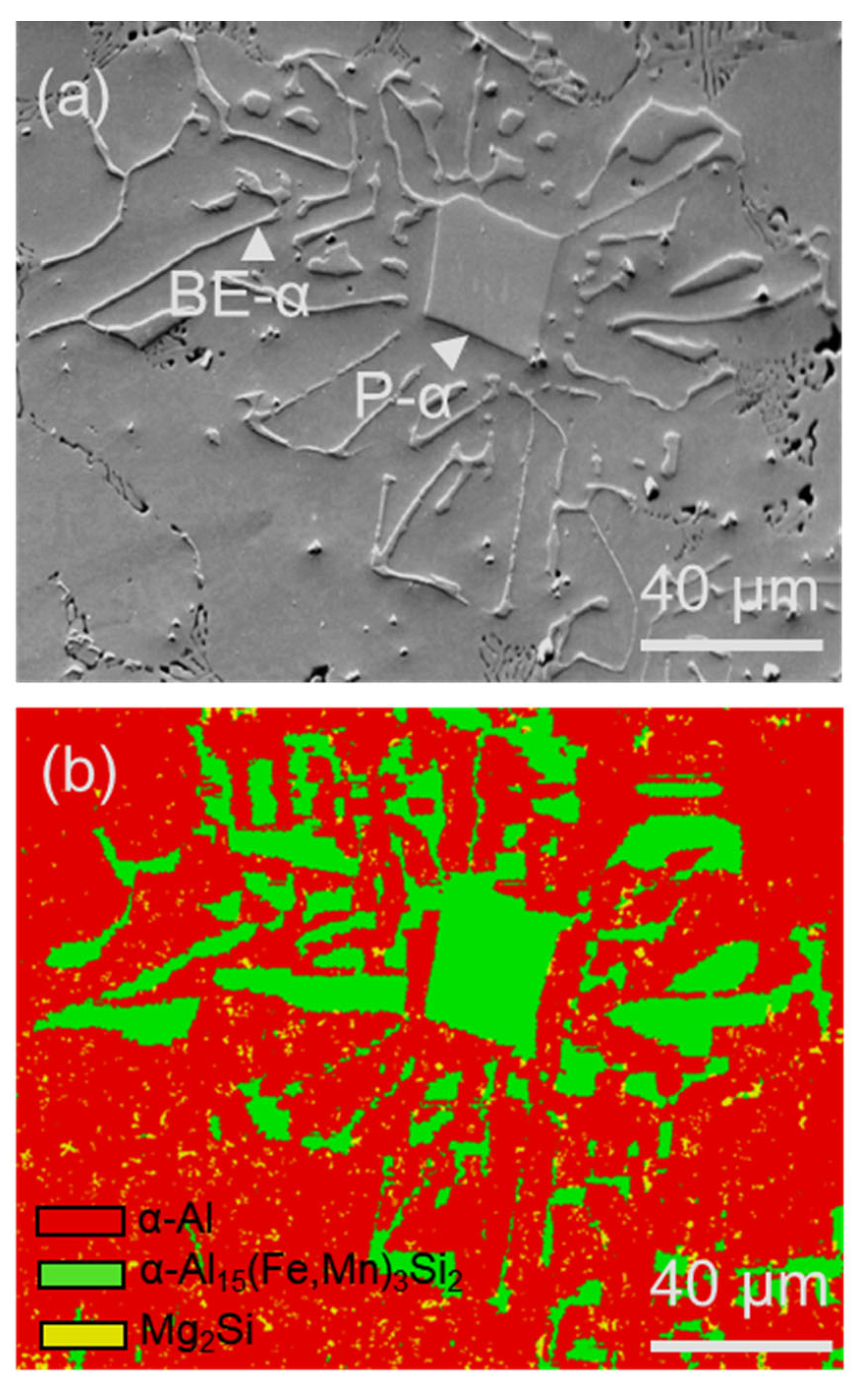
  • It has been identified that the α-Al15(Fe, Mn)3Si2 with Chinese script morphology is not the primary α, but belongs to the binary eutectic structure although it may be nucleated on (or grow from) the compacted primary α-Al15(Fe, Mn)3Si2. In addition, the compacted morphology of α-Al15(Fe, Mn)3Si2 in a ternary eutectic was observed at a slow cooling rate—0.01 K/s. It is possible that the compact ternary α-Al15(Fe, Mn)3Si2 was nucleated or grew from the binary eutectic α-Al15(Fe, Mn)3Si2.
  • Evidence of the heterogeneous nucleation of θ-Al13Fe4 on native MgAl2O4 particles was observed. A well-defined OR was observed:   2   2 ¯   2 MgAl2O4// 1   3   6 ¯ θ-Al13Fe4 and [1 1 0] MgAl2O4//3.4° [0 2 1] θ-Al13Fe4. However, it was found that the primary α-Al15(Fe, Mn)3Si2 in Al-5Mg-2Si-0.6Mn-1.3Fe alloy was not nucleated on the native oxides, but formed through solid-state phase transformation from the previously formed non-equilibrium θ-Al13Fe4 phase. Such transformations can be achieved through either a multi-step transformation or a single-step transformation. For instance, multi-step phase transformation of θ→α’→β→δ was observed in Al-20Si-0.7Fe. The phase transformation was driven by the alloy elements, especially Si diffusion. The intermediate structure (α’-Al8Fe2Si + α-Al) was also observed. The well-defined orientation relationships between θ/α’, α’/β, β/δ, θ/β and θ/α were observed. A single-step phase transformation from θ-Al13Fe4 to β-Al5FeSi was also observed with an OR: (200) θ-Al13Fe4//(003) β-Al5FeSi, and [1] θ-Al13Fe4//[100] β-Al5FeSi.
  • A compositional templating concept was proposed. Different types of alloy elements, such as Fe, Mn, and Si, can segregate on AlB2 or TiB2 particle surfaces, providing both the compositional and structural templating required by heterogeneous nucleation of FIMCs. The AlB2 or TiB2 particles with interfacial segregation of alloy elements such as Fe, Mn, and/or Si can grain-refine different types of phases. In addition, it was found that both the primary θ-Al13Fe4 and α-Al grains in Al-4Fe alloys are significantly refined by addition of 0.5 wt.% Zr by enhancing heterogeneous nucleation on the primary Al3Zr particles.

Author Contributions

Conceptualization, methodology, investigation, writing, review and editing: Z.Q.; experimental investigation, reviewing: Y.W. and C.L.M.; computer simulation investigation: C.F.; experimental investigation: J.X.; technical support: X.Z.; supervision, review and editing, visualization, and funding acquisition: Z.F. All authors have read and agreed to the published version of the manuscript.

Funding

This work was financially supported by the EPSRC (UK) under grant EP/N007638/1 (Future Liquid Metal Engineering Hub).

Data Availability Statement

Not applicable.

Conflicts of Interest

The authors declare no conflict of interest.

References

  1. International Al Institute. Global Al Recycling: A Cornerstone of Sustainable Development; International Al Institute: London, UK, 2009; pp. 6–7. [Google Scholar]
  2. Eurometax. Our Metals Future: The Metals Industry’s 2050 Vision for a Sustainable Europe; Eurometax: Woluwe-Saint-Pierre, Belgium, 2015. [Google Scholar]
  3. About Us—The Liquid Metal Engineering Hub. Available online: http://www.lime.ac.uk/about-us/ (accessed on 1 July 2022).
  4. Foresight Group. The Future of Manufacturing: A New Era of Opportunity and Challenge for the UK; Summary Report; Government Office for Science: London, UK, 2013. [Google Scholar]
  5. Aluminum Industry Worldwide-Statistics & Facts; Statista Research Department: Hamburg, Germany. 2022. Available online: http://www.statista.com/topics/2072/aluminum/#topicheader_wrapper (accessed on 1 July 2022).
  6. Aluminium for Future Generations. Available online: https://recycling.world-aluminium.org/home/ (accessed on 1 July 2022).
  7. Raabe, D.; Ponge, D.; Uggowitzer, P.; Roscher, M.; Paolantonio, M.; Liu, C.; Antrekowitsch, H.; Kozeschnik, E.; Seidmann, D.; Gault, B.; et al. Making sustainable aluminium by recycling scrap: The science of “dirty” alloys. Prog. Mater. Sci. 2022, 128, 100947. [Google Scholar] [CrossRef]
  8. Capuzzi, S.; Timelli, G. Preparation and Melting of Scrap in Aluminium Recycling: A Review. Metals 2018, 8, 249. [Google Scholar] [CrossRef] [Green Version]
  9. Brough, D.; Jouhara, H. The Al industry: A review on state-of-the-art technologies, environmental impacts and possibilities for waste heat recovery. Int. J. Thermofluids 2020, 1–2, 100007. [Google Scholar] [CrossRef]
  10. Das, S.K. Designing Aluminum Alloys for a Recycling Friendly World. Mater. Sci. Forum 2006, 519–521, 1239–1244. [Google Scholar] [CrossRef]
  11. Zhang, L.; Gao, J.; Nana, L.; Damoah, W.; Robertson, D.G. Removal of Fe from Al: A Review. Min. Proc. Ext. Met. Rev. 2012, 33, 99–157. [Google Scholar] [CrossRef]
  12. Mbuya, T.O.; Odera, B.O.; Ng’ang’a, S.P. Influence of Fe on castability and properties of Al silicon alloys: Literature review. Int. J. Cast Metals Res. 2003, 16, 451–465. [Google Scholar] [CrossRef]
  13. Yi, J.Z.; Gao, Y.X.; Lee, P.D.; Lindley, T.C. Effect of Fe-content on fatigue crack initiation and propagation in a cast aluminum-silicon alloy (A356–T6). Mater. Sci. Eng. A 2004, 386, 396–407. [Google Scholar] [CrossRef]
  14. Yang, H.; Ji, S.; Fan, Z. Effect of heat treatment and Fe content on the microstructure and mechanical properties of die-cast Al-Si-Cu alloys. Mater. Des. 2015, 85, 823–832. [Google Scholar] [CrossRef]
  15. Shen, H.; Yang, W.D.; Liang, H.; Yao, G.C. Research advance in harmful effects and removal of impurity Fe from Al and Al alloys. Adv. Mater. Res. 2011, 295–297, 751–759. [Google Scholar] [CrossRef]
  16. Nakajima, K.; Takeda, O.; Miki, T.; Matsubae, K.; Nakamura, S.; Nagasaka, T. Thermodynamic analysis of contamination by alloying elements in aluminum recycling. Environ. Sci. Technol. 2010, 44, 5594–5600. [Google Scholar] [CrossRef] [PubMed]
  17. Hess, J.B. Physical metallurgy of recycling wrought aluminum alloys. Metall. Trans. A 1983, 14, 323–327. [Google Scholar] [CrossRef]
  18. Dewan, M.A.; Rhamdhani, M.A.; Mitchell, J.B.; Davidson, C.J.; Brooks, G.A.; Easton, M.; Grandfield, J.F. Control and removal of impurities from Al melts: A review. Mater. Sci. Forum 2011, 693, 149–160. [Google Scholar] [CrossRef]
  19. Taylor, J.A. Iron-containing intermetallic phases in Al-Si based casting alloys. Procedia. Mater. Sci. 2012, 1, 19–33. [Google Scholar] [CrossRef] [Green Version]
  20. Romming, C.; Hansen, V.; Gjonnes, J. Crystal structure of β-Al4.5FeSi. Acta Crystallogr. Sect. B Struct. Sci. 1994, 50, 307–312. [Google Scholar] [CrossRef]
  21. Grin, J.; Burkhardt, U.; Peters, K. Refinement of the Fe4Al13 structure and its relationship to the quasihomological homeotypical structures, Z. Kristallogr. Cryst. Mater. 1994, 209, 479–487. [Google Scholar]
  22. Cao, X.; Campbell, J. Morphology of β-Al5FeSi phase in Al-Si cast alloys. Mater. Trans. 2006, 47, 1303–1312. [Google Scholar] [CrossRef] [Green Version]
  23. Bacaicoa, I.; Luetje, M.; Wicke, M.; Geisert, A.; Zeismann, F.; Fehlbier, M.A. Brueckner-Foit, 3D morphology of Al5FeSi inclusions in high Fe-content Al-Si-Cu alloys. Procedia Struct. Integr. 2016, 2, 2269–2276. [Google Scholar] [CrossRef] [Green Version]
  24. Ma, X.L.; Liebertz, H.; Koster, U. Multiple Twins of Monoclinic Al13Fe4 Showing Pseudo-Orthorhombic and Fivefold Symmetries. Physica. Status Solidi. A 1996, 158, 359–367. [Google Scholar] [CrossRef]
  25. Fung, K.K.; Zou, X.D.; Yang, C.Y. Transmission electron microscopy study of Al13Fe4 tenfold twins in rapidly cooled Al–Fe alloys. Philos. Mag. Lett. 1987, 55, 27–32. [Google Scholar] [CrossRef]
  26. Song, Z.; Magdysyuk, O.V.; Tang, L.; Sparks, T.; Cai, B. Growth dynamics of faceted Al13Fe4 intermetallic revealed by high-speed synchrotron X-ray quantification. J. Alloys Compd. 2021, 861, 158604. [Google Scholar] [CrossRef]
  27. Barlock, J.G.; Mondolfo, L.F. Structure of some Al-iron-magnesium-manganese-silicon alloys. Z. Metallkde. 1975, 66, 605–611. [Google Scholar]
  28. Zhu, X.Z.; Blake, P.; Dou, K.; Ji, S.X. Strengthening die-cast Al-Mg and Al-Mg-Mn alloys with Fe as a beneficial Element. Mater. Sci. Eng. A 2018, 732, 240–250. [Google Scholar] [CrossRef]
  29. Que, Z.; Zhou, Y.P.; Wang, Y.; Fan, Z. Effect of MgO on Phase Selection in Al–Mg–Si–Fe–Mn Alloys. Trans. Indian Inst. Met. 2015, 68, 1167–1172. [Google Scholar] [CrossRef]
  30. Cooper, M. The crystal structure of the tenary alloy α(AlFeSi). Acta Crystall. 1967, 23, 1106–1107. [Google Scholar] [CrossRef]
  31. Que, Z.; Wang, Y.; Fan, Z. Formation of the Fe-Containing Intermetallic Compounds during Solidification of Al-5Mg-2Si-0.7Mn-1.1Fe Alloy. Metall. Mater. Trans. A Phys. Metall. Mater. Sci. 2018, 49, 2173–2181. [Google Scholar] [CrossRef] [Green Version]
  32. Que, Z.; Wang, Y.; Fan, Z. Heterogeneous Nucleation of Eutectic Structure in Al-Mg-Si Alloys. Metall. Mater. Trans. A Phys. Metall. Mater. Sci. 2020, 51, 2697–2702. [Google Scholar] [CrossRef] [Green Version]
  33. Song, D.F.; Zhao, Y.L.; Wang, Z.; Jia, Y.W.; Li, D.X.; Fu, Y.N.; Zhang, D.T.; Zhang, W.W. 3D Fe-Rich Phases Evolution and Its Effects on the Fracture Behavior of Al–7.0Si–1.2Fe Alloys by Mn Neutralization. Acta Metall. Sin.-Engl. 2022, 35, 163–175. [Google Scholar] [CrossRef]
  34. Corby, R.N.; Blabk, P.J. The structure of alpha-(Al Fe Si) by anomalous dispersion methods. Acta Crystall. Section B: Structural Crystallography and Crystal Chemistry 1977, 33, 3468–3475. [Google Scholar] [CrossRef]
  35. Gueneau, C.; Servant, C.; d’Yvoire, F.; Rodier, N. Fe Al3Si2. Acta Crystall. Sect. C Cryst. Struct. Commun. 1995, 51, 177–179. [Google Scholar] [CrossRef]
  36. Becker, H.; Bergh, T.; Vullum, P.E.; Leineweber, A.; Li, Y. β- and δ-Al-Fe-Si intermetallic phase, their intergrowth and polytype formation. J. Alloy Compd. 2019, 780, 917–929. [Google Scholar] [CrossRef]
  37. Shabestari, S.G.; Ghanbari, M. Effect of plastic deformation and semisolid forming on iron–manganese rich intermetallics in Al–8Si–3Cu–4Fe–2Mn alloy. J. Alloys Compd. 2010, 508, 315–319. [Google Scholar] [CrossRef]
  38. Farshidi, M.H.; Rifai, M.; Miyamoto, H. Microstructure evolution of a recycled Al–Fe–Si–Cu alloy processed by tube channel pressing. Int. J. Miner. Metall. Mater. 2018, 25, 1166–1172. [Google Scholar] [CrossRef]
  39. Zhang, Y.B.; Jie, J.C.; Gao, Y.; Lu, Y.P.; Li, T.J. Effects of ultrasonic treatment on the formation of iron-containing intermetallic compounds in Al-12% Si-2% Fe alloys. Intermetallics 2013, 42, 120–125. [Google Scholar] [CrossRef]
  40. Khalifa, W.; Tsunekawa, Y.; Okumiya, M. Effect of ultrasonic treatment on the Fe-intermetallic phases in ADC12 die cast alloy. J. Mater. Process. Technol. 2010, 210, 2178–2187. [Google Scholar] [CrossRef]
  41. Nafisi, S.; Emadi, D.; Shehata, M.T.; Ghomashchi, R. Effects of electromagnetic stirring and superheat on the microstructural characteristics of Al–Si–Fe alloy. Mater. Sci. Eng. A 2006, 432, 71–83. [Google Scholar] [CrossRef]
  42. Luo, K.; Wang, Z.; Meng, L.; Guo, Z. Removal of Fe for aluminum recovery from scrap aluminum alloy by supergravity separation with manganese addition. Chem. Eng. Process. Process Intensif. 2022, 173, 108841. [Google Scholar] [CrossRef]
  43. Khan, M.H.; Das, A.; Li, Z.; Kotadia, H.R. Effects of Fe, Mn, chemical grain refinement and cooling rate on the evolution of Fe intermetallics in a model 6082 Al-alloy. Intermetallics 2021, 132, 107132. [Google Scholar] [CrossRef]
  44. Huang, H.J.; Cai, Y.H.; Cui, H.; Huang, J.F.; He, J.P.; Zhang, J.S. Influence of Mn addition on microstructure and phase formation of spray deposited Al–25Si–xFe–yMn alloy. Mater. Sci. Eng. A 2009, 502, 118–125. [Google Scholar] [CrossRef]
  45. Sha, M.; Wu, S.S.; Wang, X.T.; Wan, L. Effects of Co addition on Fe-bearing intermetallic compounds and mechanical properties of AlSi20Cu2Ni1Fe0. 7–1 alloy. J. Alloys Compd. 2013, 551, 468–474. [Google Scholar] [CrossRef]
  46. Timpel, M.; Wanderka, N.; Grothausmann, R.; Banhart, J. Distribution of Fe-rich phases in eutectic grains of Sr-modified Al–10 wt.% Si–0.1 wt.% Fe casting alloy. J. Alloys Compd. 2013, 558, 18–25. [Google Scholar] [CrossRef]
  47. Ashtari, P.; Tezuka, H.; Sato, T. Influence of Li addition on intermetallic compound morphologies in Al–Si–Cu–Fe cast alloys. Scr. Mater. 2004, 51, 43–46. [Google Scholar] [CrossRef]
  48. Liu, K.; Cao, X.; Chen, X.G. Effect of Mn, Si, and cooling rate on the formation of iron-rich intermetallics in 206 Al-Cu cast alloys. Metall. Mater. Trans. B 2012, 43, 1231–1240. [Google Scholar] [CrossRef]
  49. Kim, H.Y.; Han, S.W.; Lee, H.M. The influence of Mn and Cr on the tensile properties of A356–0.20Fe alloy. Mater. Lett. 2006, 60, 1880–1883. [Google Scholar] [CrossRef]
  50. Jin, L.; Liu, K.; Chen, X.G. Evolution of Fe-rich intermetallics in Al-Si-Cu 319 cast alloy with various Fe, Mo, and Mn contents. Metall. Mater. Trans. B 2019, 50, 1896–1907. [Google Scholar] [CrossRef]
  51. Mahta, M.; Emamy, M.; Daman, A.; Keyvani, A.; Campbell, J. Precipitation of Fe rich intermetallics in Cr- and Co-modified A413 alloy. Int. J. Cast Met. Res. 2005, 18, 73–79. [Google Scholar] [CrossRef]
  52. Sweet, L.; Zhu, S.M.; Gao, S.X.; Taylor, J.A.; Easton, M.A. The effect of iron content on the iron-containing intermetallic phases in a cast 6060 aluminum alloy. Metall. Mater. Trans. A Phys. Metall. Mater. Sci. 2011, 42, 1737–1749. [Google Scholar] [CrossRef]
  53. Basak, C.B.; Meduri, A.; Babu, N.H. Influence of Ni in high Fe containing recyclable Al-Si cast alloys. Mater. Des. 2019, 182, 108017. [Google Scholar] [CrossRef]
  54. Zhang, Z.; Li, G.; Chen, X.G. Effect of nickel and vanadium on iron bearing intermetallic phases in AA 5657 simulated DC castings. Mater. Sci. Technol. 2014, 30, 951–961. [Google Scholar] [CrossRef]
  55. Tzeng, Y.C.; Wu, C.T.; Bor, H.Y.; Horng, J.L.; Tsai, M.L.; Lee, S.L. Effects of scandium addition on iron-bearing phases and tensile properties of Al-7Si-0.6Mg alloys. Mater. Sci. Eng. A 2014, 593, 103–110. [Google Scholar] [CrossRef]
  56. Basak, C.B.; Babu, N.H. Influence of Cu on modifying the beta phase and enhancing the mechanical properties of recycled Al-Si-Fe cast alloys. Sci. Rep. 2017, 7, 5779. [Google Scholar] [CrossRef] [PubMed] [Green Version]
  57. Wan, B.; Chen, W.; Liu, L.; Cao, X.; Zhou, L.; Fu, Z. Effect of trace yttrium addition on the microstructure and tensile properties of recycled Al-7Si-0.3Mg-1.0Fe casting alloys. Mater. Sci. Eng. A 2016, 666, 165–175. [Google Scholar] [CrossRef]
  58. Song, D.F.; Jia, Y.W.; Li, Q.; Zhao, Y.L.; Zhang, W.W. Effect of initial Fe content on Microstructure and Mechanical Properties of Recycled Al-7.0Si-Fe-Mn alloys with Constant Mn/Fe ratio. Materials 2022, 15, 1618. [Google Scholar] [CrossRef] [PubMed]
  59. Baldan, R.; Malavazi, J.; Couto, A.A. Microstructure and mechanical behavior of Al9Si0.8Fe alloy with different Mn contents. Mater. Sci. Technol. 2017, 33, 1192–1199. [Google Scholar] [CrossRef]
  60. Ceschini, L.; Boromei, I.; Morri, A.; Seifeddine, S.; Svensson, I.L. Microstructure, tensile and fatigue properties of the Al-10%Si-2%Cu alloy with different Fe and Mn content cast under controlled conditions. J. Mater. Process Technol. 2009, 209, 5669–5679. [Google Scholar] [CrossRef]
  61. Hwang, J.Y.; Doty, H.W.; Kaufman, M.J. The effects of Mn additions on the microstructure and mechanical properties of Al-Si-Cu casting alloys. Mater. Sci. Eng. A 2008, 488, 496–504. [Google Scholar] [CrossRef]
  62. Cao, X.; Campbell, J. The nucleation of Fe-rich phases on oxide films in Al-11.5Si-0.4Mg cast alloys. Metall. Mater. Trans. A 2003, 34, 1409–1420. [Google Scholar] [CrossRef]
  63. Que, Z.P.; Wang, Y.; Zhou, Y.P.; Fan, Z. Effect of Al-5Ti-1B Grain Refiner Addition on the Formation of Intermetallic Compounds in Al-Mg-Si-Mn-Fe Alloys. Mater. Sci. Forum 2015, 828–829, 53–57. [Google Scholar] [CrossRef]
  64. Khalifa, W.; Samuel, F.H.; Gruzleski, J.E.; Doty, H.W.; Valtierra, S. Nucleation of Fe-intermetallic phases in the Al-Si-Fe alloys. Metall. Mater. Trans. A 2005, 36, 1017–1032. [Google Scholar] [CrossRef]
  65. Lui, A.; Grant, P.S.; Stone, I.C.; O’Reilly, K.A.Q. The role of grain refiner in the nucleation of AlFeSi intermetallic phases during solidification of a 6xxx Aluminum alloy. Metall. Mater. Trans. A 2019, 50, 5242–5252. [Google Scholar] [CrossRef] [Green Version]
  66. Que, Z.; Mendis, C.L. Heterogeneous nucleation and phase transformation of Fe-rich intermetallic compounds in Al–Mg–Si alloys. J. Alloys Compd. 2020, 836, 155515. [Google Scholar] [CrossRef]
  67. Que, Z.; Mendis, C.L. Formation of θ-Al13Fe4 and the multi-step phase transformations to α-Al8Fe2Si, β-Al5FeSi and δ-Al4FeSi2 in Al–20Si-0.7Fe alloy. Intermetallics 2020, 127, 106960. [Google Scholar] [CrossRef]
  68. Sha, G.; O’Reilly, K.A.Q.; Cantor, B.; Titchmarsh, J.M.; Hamerton, R.G. Quasi-peritectic solidification reactions in 6xxx series wrought Al-alloys. Acta Mater. 2003, 51, 1883–1897. [Google Scholar] [CrossRef]
  69. Gorny, A.; Manickaraj, J.; Cai, Z.; Shankar, S. Evolution of Fe based intermetallic phases in Al–Si hypoeutectic casting alloys: Influence of the Si and Fe concentrations, and solidification rate. J. Alloys Compd. 2013, 577, 103–124. [Google Scholar] [CrossRef]
  70. Liu, P.; Dunlop, G.L. Crystallographic orientation relationships for Al–Fe and Al–Fe–Si precipitates in aluminium. Acta Metall. 1988, 36, 1481–1489. [Google Scholar] [CrossRef]
  71. Choi, Y.S.; Lee, J.S.; Kim, W.T.; Ra, H.Y. Solidification behavior of Al-Si-Fe alloys and phase transformation of metastable intermetallic compound by heat treatment. J. Mater. Sci. 1999, 34, 2163–2168. [Google Scholar] [CrossRef]
  72. Ashtari, P.; Gatenby, K. Reheating of solid shell during twin belt-casting of an Al–Fe–Si alloy. Scr. Mater. 2008, 58, 150–153. [Google Scholar] [CrossRef]
  73. Pereira, L.H.; Asato, G.H.; Otani, L.B.; Jorge, A.M.; Kiminami, C.S.; Bolfarini, C.; Botta, W.J. Changing the solidification sequence and the morphology of iron-containing intermetallic phases in AA6061 Al-alloy processed by spray forming. Mater. Charact. 2018, 145, 507–515. [Google Scholar] [CrossRef]
  74. Al-Helal, K.; Lazaro-Nebreda, J.; Patel, J.B.; Scamans, G.M. High-shear De-Gassing and de-ironing of an Aluminum casting alloy made directly from aluminum end-of-life vehicle scrap. Recycling 2021, 6, 66. [Google Scholar] [CrossRef]
  75. Lazaro-Nebreda, J.; Patel, J.B.; Chang, I.T.H.; Stone, I.C.; Fan, Z. Solidification processing of scrap Al-alloys containing high levels of Fe. IOP Conf. Ser. Mater. Sci. Eng. 2019, 529, 012059. [Google Scholar] [CrossRef]
  76. Li, H.-T.; Zhao, P.; Yang, R.; Patel, J.B.; Chen, X.; Fan, Z. Grain Refinement and Improvement of Solidification Defects in Direct-Chill Cast Billets of A4032 Alloy by Melt Conditioning. Metall. Mater. Trans. B 2017, 48, 2481–2492. [Google Scholar] [CrossRef] [Green Version]
  77. Sree Manu, K.M.; Barekar, N.S.; Lazaro-Nebreda, J.; Patel, J.B.; Fan, Z. In-situ microstructural control of A6082 alloy to modify second phase particles by melt conditioned direct chill (MC-DC) casting process—A novel approach. J. Mater. Process. Technol. 2021, 295, 117170. [Google Scholar]
  78. Available online: https://computherm.com/panaluminum (accessed on 1 July 2022).
  79. Scheil, E. Bemerkungen zur schichtkristallbildung. Z. Metallkd. 1942, 34, 70–72. [Google Scholar] [CrossRef]
  80. Que, Z.; Fang, C.M.; Chamini, L.; Mendis, C.L.; Wang, Y.; Fan, Z. Effects of Si solution in Al13Fe4 on phase transformation between Fe-containing intermetallic compounds in Al-alloys. J. Alloys Compd. 2022. Revised. [Google Scholar]
  81. Fang, C.M.; Que, Z.; Dinsdale, A.; Fan, Z. Si solution in θ-Al13Fe4 from first-principles. Intermetallics 2020, 126, 106939. [Google Scholar] [CrossRef]
  82. Que, Z.; Wang, Y.; Fan, Z.; Hashimoto, T.; Zhou, X. Enhanced heterogeneous nucleation of Al6(Fe,Mn) compound in Al-alloys by interfacial segregation of Mn on TiB2 particles surface. Mater. Lett. 2022, 323, 132570. [Google Scholar] [CrossRef]
  83. Que, Z.; Zhou, Y.; Wang, Y.; Mendis, C.L.; Fan, Z. Effects of Mg addition on the Al6(Fe,Mn) intermetallic compounds and the grain refinement of α-Al in Al-Fe-Mn alloys. Mater. Charact. 2020, 171, 110758. [Google Scholar] [CrossRef]
  84. Que, Z.; Zhou, Y.; Wang, Y.; Fan, Z. Proceedings of the 6th Decennial Conference on Solidification Processing 2017. Old Windsor, UK, 25–28 July 2017; pp. 158–161. [Google Scholar]
  85. Gao, F.; Fan, Z. Competition for nucleation and grain initiation during solidification. Metals 2022, 12, 1512. [Google Scholar] [CrossRef]
  86. Fang, C.; Dinsdale, A.; Que, Z.; Fan, Z. Intrinsic defects in and electronic properties of θ-Al13Fe4: An ab initio DFT study. J. Phys. Mater. 2019, 2, 015004. [Google Scholar] [CrossRef]
  87. Fang, C.; Que, Z.; Fan, Z. Crystal Chemistry and Electronic Structure of the β-AlFeSi Phase from First-Principles. J. Solid State Chem. 2021, 299, 122199. [Google Scholar] [CrossRef]
  88. Dinsdale, A.; Fang, C.; Que, Z.; Fan, Z. Understanding the Thermodynamics and Crystal Structure of Complex Fe Containing Intermetallic Phases Formed on Solidification of Al-alloys. JOM 2019, 71, 1731–1736. [Google Scholar] [CrossRef] [Green Version]
  89. Fan, Z. An Epitaxial Model for Heterogeneous Nucleation on Potent Substrates. Metall. Mater. Trans. A 2013, 44, 1409–1418. [Google Scholar] [CrossRef] [Green Version]
  90. Easton, M.A.; Qian, M.; Prasad, A.; Stjohn, D.H. Recent advances in grain refinement of light metals and alloys. Curr. Opin. Solid State Mater. Sci. 2016, 20, 13–24. [Google Scholar] [CrossRef] [Green Version]
  91. Vainik, R.; Courtenay, J.; Byrant, M. Optimum grain refining with a high performance master alloy. Al Today Int. 2009, 21, 25–26, 28. [Google Scholar]
  92. Greer, A.L.; Cooper, P.S.; Meredith, M.W.; Schneider, W.; Schumacher, P.; Spittle, J.A.; Tronche, A. Grain refinement of Al-alloys by inoculation. Adv. Eng. Mater. 2003, 5, 81–91. [Google Scholar] [CrossRef]
  93. Murty, B.S.; Kori, S.A.; Chakraborty, M. Grain refinement of Al and its alloys by heterogeneous nucleation and alloying. Int. Mater. Rev. 2002, 47, 3–29. [Google Scholar] [CrossRef]
  94. Fan, Z.; Wang, Y.; Zhang, Y.; Qin, T.; Zhou, X.R.; Thompson, G.E.; Pennycook, T.; Hashimoto, T. Grain refining mechanism in the Al/Al–Ti–B system. Acta Mater. 2015, 84, 292–304. [Google Scholar] [CrossRef]
  95. Wang, Y.; Fang, C.M.; Zhou, L.; Hashimoto, T.; Zhou, X.; Ramasse, Q.M.; Fan, Z. Mechanism for Zr poisoning of Al-Ti-B based grain refiners. Acta Mater. 2019, 164, 428–439. [Google Scholar] [CrossRef] [Green Version]
  96. Wang, Y.; Que, Z.; Hashimoto, T.; Zhou, X.; Fan, Z. Mechanism for Si Poisoning of Al-Ti-B Grain Refiners in Al-alloys. Metall. Mater. Trans. A: Phy. Metall. Mater. Sci. 2020, 51, 5743–5757. [Google Scholar]
  97. Que, Z.; Wang, Y.; Mendis, C.L. Heterogeneous nucleation of α-Al on naturally formed MgAl2O4 particles during solidification of Al–Mg–Si–Fe–Mn alloys. Materialia 2020, 14, 100900. [Google Scholar] [CrossRef]
  98. Que, Z.; Mendis, C.L. Effects of native AlN particles on heterogeneous nucleation in an Al-3Fe Alloy. Metall. Mater. Trans. A Phy. Metall. Mater. Sci. 2020, 52, 553–559. [Google Scholar] [CrossRef]
  99. Wang, S.H.; Wang, Y.; Ramasse, Q.M.; Schmid-Fetzer, R.; Fan, Z. Segregation of yttrium at Mg/MgO interface in Mg-Y alloy. Acta Mater, 2022; Submitted. [Google Scholar]
  100. Rosenhain, W.; Grogan, J.D.; Schofield, T.H. Gas removal and grain refinement in Al-alloys. J. Inst. Met. 1930, 44, 305–318. [Google Scholar]
  101. McCartney, D.G. Grain refining of Al and its alloys using inoculants. Int. Mater. Rev. 1989, 34, 247–260. [Google Scholar] [CrossRef]
  102. Que, Z.; Xia, J.; Fan, Z. Effects of Zr addition on the grain refinement of α-Al and Al13Fe4 in Al-4Fe alloy. Unpublished.
  103. Cibula, A. The mechanism of grain refinement of sand castings in Al-alloys. J. Inst. Met. 1949, 76, 321–360. [Google Scholar]
  104. Guan, R.G.; Tie, D. A Review on Grain Refinement of Aluminum Alloys: Progresses, Challenges and Prospects. Acta Metall. Sin. 2017, 30, 409–432. [Google Scholar] [CrossRef] [Green Version]
  105. Fan, Z.; Gao, F.; Jiang, B.; Que, Z. Impeding Nucleation for More Significant Grain Refinement. Sci. Rep. 2020, 10, 9448. [Google Scholar]
  106. Fan, Z.; Men, H.; Wang, Y.; Que, Z. A New Atomistic Mechanism for Heterogeneous Nucleation in the Systems with Negative Lattice Misfit: Creating a 2D Template for Crystal Growth. Metals 2021, 11, 478. [Google Scholar] [CrossRef]
  107. Liu, X.; Wang, C.; Zhang, S.Y.; Song, J.W.; Zhou, X.L.; Zha, M.; Wang, H.Y. Fe-bearing phase formation, microstructure evolution, and mechanical properties of Al-Mg-Si-Fe alloy fabricated by the twin-roll casting process. J. Alloys Compd. 2021, 886, 161202. [Google Scholar] [CrossRef]
  108. Zhang, X.; Wang, D.; Li, X.; Zhang, H.; Nagaumi, H. Understanding crystal structure and morphology evolution of Fe, Mn, Cr-containing phases in Al-Si cast alloy. Intermetallics 2021, 131, 107103. [Google Scholar] [CrossRef]
  109. Zhang, X.; Wang, D.; Zhou, Y.; Chong, X.; Li, X.; Zhang, H.; Nagaumi, H. Exploring crystal structures, stability and mechanical properties of Fe, Mn-containing intermetallics in Al-Si alloy by experiments and first-principles calculations. J. Alloys Compd. 2021, 876, 160022. [Google Scholar] [CrossRef]
Figure 4. The Chinese script eutectic α-Al15(Fe,Mn)3Si2 is nucleated from the compacted primary α-Al15(Fe, Mn)3Si2. (a) SEM-SEI image, and (b) EBSD maps of Al-5Mg-2Si-0.6Mn-1.3Fe alloys solidified at 3.5 K/s from a pouring temperature of 720 °C, showing a compacted Al15(Fe, Mn)3Si2 particle has same orientation with the Chinese script α-Al15(Fe, Mn)3Si2 in binary eutectic [66].
Metals 12 01677 g004
Figure 5. Different morphologies of α-Al15(Fe, Mn)3Si2: (a) extracted primary α-Al15(Fe, Mn)3Si2 (denoted as P-α) with a compact morphology in Al-5Mg-2Si-0.7Mn-1.3Fe alloy solidified at 3.5 K/s [31]; (b) binary eutectic α-Al15(Fe, Mn)3Si2 (denoted as BE-α) with a Chinese script morphology in Al-3Mg-2Si-0.7Mn-1.3Fe alloy solidified at 3.5 K/s. The sample was deep-etched; and (c) ternary eutectic α-Al15(Fe, Mn)3Si2 (denoted as TE-α) with compact morphology in Al-2Si-0.7Mn-1.3Fe alloy solidified at 0.01 K/s.
Metals 12 01677 g005
Figure 6. The calculated phase diagram of Al-11.7Si-0.6Mn-xFe under Scheil model condition showing that the α-Al15(Fe, Mn)3Si2 is the calculated equilibrium phase for Al-11.7Si-0.6Mn-2.8Fe alloy. Note the orange point shown in the diagram indicates the alloy composition of Al-11.7Si-0.6Mn-2.8Fe alloy.
Metals 12 01677 g006
Figure 7. SEM-BSE images showing the as-cast microstructure of Al-11.7Si-0.6Mn-2.8Fe alloy solidified at 3.5 K/s. (a) Without grain refiner addition, the primary FIMCs are mainly α-Al15(Fe, Mn)3Si2 with a few primary β-Al5FeSi; (b) eutectic area from (a) contains the plate-like binary eutectic β-Al5FeSi; (c) with 1000 ppm grain refiner addition, the primary FIMC becomes β-Al5FeSi, and (d) the binary eutectic area contains Chinese script α-Al15(Fe,Mn)3Si2. This suggests that the phase competition of primary FIMCs affects the subsequent formation of the BE-FIMCs.
Metals 12 01677 g007
Figure 8. X-ray computed tomography (CT) image showing the cross-section of Al-5Mg-2Si-0.6Mn-1.0Fe alloy solidified at 0.01 K/s indicated that the PIMCs compacted particles contain central brighter particles indicating a different FIMC to the surface structure [66].
Metals 12 01677 g008
Figure 9. The non-equilibrium primary θ-Al13Fe4 (P-θ) was formed first in the liquid, and the equilibrium compact primary α-Al15(Fe, Mn)3Si2 grows on the P-θ. [66] (a) SEM-SEI image showing the α-Al15(Fe, Mn)3Si2 particle with central θ-Al13Fe4 in Al-5Mg-2Si-0.6Mn-1.3Fe alloy solidified at 0.01 K/s from a pouring temperature of 720 °C; (b) EBSD mapping identified θ-Al13Fe4 and α-Al in α-Al15(Fe, Mn)3Si2 particle; and (c) HRTEM image viewed along the [0 1 0] zone axis of θ-Al13Fe4 and [1 0 0] zone axis of α-Al15(Fe, Mn)3Si2, showing the orientation relationship between θ-Al13Fe4 and α-Al15(Fe, Mn)3Si2: 2 ¯   0   1 θ-Al13Fe4//2.3° 0   1 ¯   1 α-Al15(Fe, Mn)3Si2, and [0 1 0] θ-Al13Fe4//[1 0 0] α-Al15(Fe, Mn)3Si2. [66].
Metals 12 01677 g009
Figure 10. Schematic illustration of the competition for nucleation between two different types of FIMCs, A and B. TA and TB are the equilibrium formation temperatures of A and B, respectively. TnA and TnB are the actual nucleation temperatures of A and B, respectively. ∆TnA and ∆TnB are the actual nucleation undercoolings of A and B, respectively. Under such circumstances, B will nucleate first, although A has a higher formation temperature than B.
Metals 12 01677 g010
Figure 11. The calculated solidification curve for Al-20Si-0.7Fe alloy using the Scheil model showing that solidification starts at 688 °C with the formation of the equilibrium primary Si phase, which is followed by the formation of δ-Al4FeSi2 + Si eutectic at 609 °C and β-Al5FeSi + Si eutectic at 597 °C.
Metals 12 01677 g011
Figure 12. The multi-step phase transformation from θ to α’-Al8Fe2Si, β-Al5FeSi, then δ-Al4FeSi2 observed with SEM-BSE mode in Al-20Si-0.7Fe alloy, which solidified at 0.01 K/s. (a) SEM-BSE image showing the elongated θ-Al13Fe4; (b) the detailed microstructure in the area marked by the white frame in (a) showing a complex multi-phase zone containing θ-Al13Fe4, α’-Al8Fe2Si +α-Al and β-Al5FeSi phases; (c) a EBSD map for phase identification; and (d) δ-Al4FeSi2 with a higher Si content was formed on the edge of FIMC particles after heat treatment at 530 °C for 30 min, and (e) the SEM-EDS spectra of θ, β and δ shown in (d) [67].
Metals 12 01677 g012
Figure 13. High-resolution TEM (HRTEM) images showing the interfaces between different types of FIMCs in Al-20Si-0.7Fe alloy solidified at 0.01 K/s. (a) the interface between α’-Al8Fe2Si and θ-Al13Fe4, with the incident electron beam being paralleled to [ 1 ¯ 3 ¯ 4 ¯ ] zone direction of θ-Al13Fe4 and [ 3 ¯ 2 1 ¯ ] zone direction of α′-Al8Fe2Si; (b) the β-Al5FeSi/α′-Al8Fe2Si interface with the incident electron beam being parallel with [0 1 0] zone direction of β-Al5FeSi and [1 2 3] zone direction of α′-Al8Fe2Si, (c) the β-Al5FeSi/δ-Al4FeSi2 interface viewed along the [110] zone direction of β-Al5FeSi and δ-Al4FeSi2 in Al-20Si-0.7Fe alloy after heat treatment at 530 °C for 0.5 h. [67].
Metals 12 01677 g013
Figure 14. One-step phase transformation between θ-Al13Fe4 and β-Al5FeSi. (a) SEM-BSE image showing the microstructure of primary θ-Al13Fe4 phase in Al-4Si-4Fe alloy solidified at 3.5 K/s—the primary θ-Al13Fe4 phase had transformed into the other FIMCs from the edge to centre with plate-like morphology; and (b) HRTEM image of the β-Al5FeSi/Al13Fe4 interface viewed along the zone direction of [0 0 1] of Al13Fe4 and [1 0 0] of β-Al5FeSi showing the orientation relationship between β-Al5FeSi and θ-Al13Fe4 [80].
Metals 12 01677 g014
Figure 15. SEM (in lens) image showing (a) the 2-dimension and (b) 3-dimension the native MgAl2O4 par-ticles in prefilled Al-3Fe-1Mg.
Metals 12 01677 g015
Figure 16. Heterogeneous nucleation of θ-Al13Fe4 on a native MgAl2O4 particle. (a) HRTEM image of MgAl2O4 with the electron beam paralleled to <1 1 0> zone axis showing {1 1 1} faceting on the MgAl2O4 particle, (b) HRTEM image showing the MgAl2O4/θ-Al13Fe4 interface with electron beam parallel to [110] of MgAl2O4 and [21] of θ-Al13Fe4, revealing an orientation relationship (OR) between the oxide and θ-Al13Fe4: 2   2 ¯   2 MgAl2O4// 1   3   6 ¯ θ-Al13Fe4 and [1 1 0] MgAl2O4//3.4° [0 2 1] θ-Al13Fe4. [67].
Metals 12 01677 g016
Figure 17. Grain refinement of θ by enhancing the heterogeneous nucleation on Al3Zr particles in Al-4Fe alloy with 0.5 wt.% Zr addition. (a) optical micrograph of Al-4Fe solidified at 3.5 K/s, (b) optical micrographs of Al-4Fe-0.5Zr solidified at 3.5 K/s showing the refinement of Fe-containing particles with the Zr addition; and (c) SEM image of deep-etched Al-4Fe-0.5Zr alloy showing the θ-Al13Fe4 particles associated with Al3Zr particles. [102].
Metals 12 01677 g017
Figure 18. Grain refinement of α-Al grains in Al-4Fe alloy with 0.5 wt.% Zr addition: (a) optical micrographs of Al-4Fe solidified at 3.5 K/s; and (b) optical micrograph of Al-4Fe-0.5Zr solidified at 3.5 K/s showing the refinement of α-Al grains with the Zr addition. [102].
Metals 12 01677 g018
Figure 19. Interfacial segregation of Mn at the α-Al/ 10 1 ¯ 0 TiB2 interface. (a) Scanning transmission electron microscopy (STEM) Z-contrast high-angle annular dark field (HAADF) image of Al/TiB2 interface in Al-3.7Ti-1.5B alloy, viewed along 1   1   2 ¯   0 TiB2 direction; and (bd) Super-X EDS elemental mapping of (b) Al, (c) Ti, and (d) Mn [82].
Metals 12 01677 g019
Figure 20. Mn-modified TiB2 particles nucleate η-Al6(Fe, Mn) phase and refine η-Al6(Fe, Mn) phase in Al-2Mn-1.0Fe alloy. SEM images showing the microstructure of Al-2Mn-1.0Fe alloy solidified at 3.5 K/s (a) without grain refiner addition, (b) with 1000 ppm novel grain refiner addition (Mn-modified TiB2 particles); (c) TEM bright-field image showing the TiB2/η-Al6(Fe, Mn) interface, (d) high-resolution TEM image showing the modified TiB2/η-Al6(Fe, Mn) interface. [82].
Metals 12 01677 g020
Table 1. Crystal lattice parameter of FIMC phases from literature.
Alloysa (Å)b (Å)c (Å)α(º)β(º)γ(º)ICSD Collect CodeReferences
θ-Al13Fe415.4928.07812.47190107.6990151129[21]
α’- Al8Fe2Si12.40412.40426.23490901201293[34]
β-Al5FeSi 6.1616.17520.8139090.429074569[20]
α-Al15(Fe, Mn)3Si212.5612.5612.5690909052623[30]
δ-Al4FeSi26.0616.0619.52590909079710[35]
η-Al6(Fe, Mn)7.4986.4958.837909090607582[27]
Table 2. The composition (wt.%) of different Al alloys investigated in this work.
AlloysTL (°C)PETp (°C)Wt.%
FeMnSiMg
Al-3Fe 805θ-Al13Fe48603.13 ± 0.060.01 ± 0.00--
Al-4Si-4Fe 715θ-Al13Fe47604.10 ± 0.050.05 ± 0.004.21 ± 0.060.003 ± 0.00
Al-5Mg-2Si-0.7Mn-1.3Fe 668α-Al15(Fe, Mn)3Si27201.29 ± 0.030.68 ± 0.022.11 ± 0.035.43 ± 0.05
Al-3Mg-2Si-0.7Mn-1.3Fe 662α-Al15(Fe, Mn)3Si27201.25 ± 0.060.64 ± 0.022.15 ± 0.033.05 ± 0.05
Al-5Mg-2Si-0.4Mn-0.7Fe 638α-Al15(Fe, Mn)3Si26900.67 ± 0.20.44 ± 0.22.65 ± 0.25.66 ± 0.6
Al-12Si-0.6Mn-2.8Fe 648α-Al15(Fe, Mn)3Si27002.8 ± 0.050.6 ± 0.0111.7 ± 0.2-
Al-20Si-0.7Fe 688Si7500.65 ± 0.05-20.5 ± 0.5-
Al-16Si-3Fe 670β-Al5FeSi7203.3 ± 0.05 13 ± 0.3
Al-2Mn-1Fe 664η-Al6(Fe, Mn)7201.0 ± 0.022.2 ± 0.02--
Al-4Fe 850θ-Al13Fe49004.37 ± 0.05---
Note: TL: calculated melting temperature with Scheil model; PE: calculated equilibrium primary phase with Scheil model; Tp: pouring temperature during casting.
Table 5. Refinement of different phases in Al alloys.
Grain Size (μm)CP-Al
(α-Al)
Al-5Mg-2Si-0.7Mn-1.3Fe
(α-Al15(Fe, Mn)3Si2)
Al-12Si-0.7Mn-2.8Fe
(β-Al5FeSi)
Al-27Si
(Si)
Al-2Mn-1Fe
(η-Al6(Fe, Mn))
No grain refinerFully columnar38.7 ± 6.8μm1178.4 ± 135 μm461 ± 51 μm26.0 ± 2.1 μm
AlB2(Fe, Si)-19.2 ± 5.6 μm---
TiB2(Mn)----9.5 ± 0.6 μm
TiB2(Fe, Si)-11.1 ± 4.4 μm425.2 ± 61 μm39 ± 5.5 μm-
Publisher’s Note: MDPI stays neutral with regard to jurisdictional claims in published maps and institutional affiliations.

