Article

The Microstructure, Mechanical Properties, and Corrosion Resistance of a Novel Extruded Titanium Alloy

1
School of Mechanical and Automotive Engineering, Qingdao University of Technology, Qingdao 266520, China
2
School of Materials Science and Engineering, Northeastern University, Shenyang 110819, China
3
School of Materials Science and Engineering, Harbin Institute of Technology, Harbin 150006, China
*
Author to whom correspondence should be addressed.
Metals 2022, 12(10), 1564; https://doi.org/10.3390/met12101564
Submission received: 31 August 2022 / Revised: 19 September 2022 / Accepted: 20 September 2022 / Published: 21 September 2022
(This article belongs to the Special Issue Hot Forming/Processing of Metallic Materials)

Abstract

:
Titanium alloys are widely used in marine engineering and other industries. To broaden their application, a novel (α + β) titanium alloy Ti−6Al−3Mo−2Zr−2Fe was studied in this work. A tube with an outer diameter of 60mm, inner diameter of 38 mm, and length of 500 mm was produced by ingot metallurgy and hot extrusion. The microstructure, mechanical properties, and corrosion resistance of the tube were systematically analyzed. The as−extruded Ti−6Al−3Mo−2Zr−2Fe alloy exhibited a typical duplex microstructure. EBSD observation showed that a strong < 10   1 ¯ 0 >//RD fiber texture of an α phase with a close−packed hexagonal structure was formed in the radial direction. The transformation temperature Tβ was determined to be 880–890 °C. A duplex microstructure with fine α platelets was obtained when the alloy was solution−treated at 850 °C for 1 h and underwent an aging treatment at 550 °C for 6 h. The room−temperature tensile strength and elongation of the aged alloy reached 1081.5 MPa and 6.5%, respectively. The corrosion resistance was tested by open circuit potential and a potentiodynamic polarization curve. The results show that the corrosion resistance of the Ti−6Al−3Mo−2Zr−2Fe alloy was better than that of the commonly used TC4 alloy in both a 3.5% NaCl solution and an acidic solution.

1. Introduction

As promising lightweight structure materials, titanium alloys are widely used in many industrial fields [1], such as marine engineering [2], aerospace [3], and automobile industries [4], owing to their low density, high specific strength, and excellent corrosion resistance. Their density is about 57 percent that of steel, which contributes to the light weight of equipment [5]. The yield strength of high−strength titanium alloys can be higher than 790 MPa [6]. The service life of equipment can be greatly increased in corrosive environments by replacing stainless steel with titanium alloys [7].
Marine engineering is one of the important application fields of titanium alloys. Titanium alloys with excellent corrosion resistance can be used to fabricate shallow exploration equipment [8], seawater purification devices [9], oil platform components [10], etc. A series of typical alloy compositions have been developed after years of research [11,12,13]. Marine titanium alloys in Russia mainly resemble α titanium alloys such as Ti−6.5Al−3.3Mo−0.3Si and Ti−5Al−3Mo−1V. Marine titanium alloys in America are developed based on aerospace titanium alloys, which have good corrosion resistance in seawater environments such as Ti−6Al−4V−ELI and Ti−3Al−8V−6Cr−4Mo−4Zr. However, a proper balance between high strength and better corrosion resistance is not easy to achieve. It is necessary to develop novel titanium alloys to meet the demand. Mo is a typical corrosion−resistant element for titanium alloys. The addition of Mo can promote the formation of spontaneous passivation, thereby improving the corrosion resistance of titanium alloys [14]. The addition of Zr can enhance the chemical dissolution resistance of TiO2 passivation film [15]. The strength of titanium alloys can also be improved by adding Nb and Zr [16]. Moreover, Fe is a low−cost alloying element for Ti alloys [17]. The addition of Fe can refine the size of the secondary α phase [18], which is conducive to the microstructure’s homogenization. Based on the above analysis, a novel Ti−6Al−3Mo−2Zr−2Fe alloy is considered to have good comprehensive properties. The goal of this work is to study the microstructure, mechanical properties, and corrosion resistance of a Ti−6Al−3Mo−2Zr−2Fe alloy. It can provide a new choice for marine engineering.

2. Materials and Methods

The ingot of the Ti−6Al−3Mo−2Zr−2Fe alloy was prepared by vacuum induction melting (ISM) technology and subsequently forged at a high temperature six times. X−ray fluorescence spectrometry (XRF, PANalytical Axios, PANalytical B.V, Almelo, Netherlands) revealed that the actual composition of the ingot was Ti−6.2Al−2.92Mo−1.96Zr−1.87Fe. The impurity was also measured by an oxygen/nitrogen/hydrogen analyzer (ONH836, Leco, San Jose, America). The contents of oxygen, nitrogen, and hydrogen were 0.08 wt%, 0.029 wt%, and 0.012 wt%, respectively. The billet was extruded at a high temperature with an extrusion ratio of 10:1. Then, a tube with an outer diameter of 60 mm, inner diameter of 38 mm, and length of 500 mm was obtained. Samples with dimensions of 10 mm × 10 mm × 4 mm were cut along the radial and axial directions of the tube using a wire cutting machine, as shown in Figure 1. Samples were polished with SiC sandpaper and polishing paste (2.5 W) and etched with Kroll’s reagent. The microstructure was observed by scanning electron microscopy (SEM, ZEISS−Sigma 300, Carl Zeiss, Oberkochen, Germany). The sample for the electron backscatter diffraction (EBSD) was electrolytically polished by a 60% methanol + 30% n−butanol + 10% perchloric acid mixed solution. The phase composition was analyzed by X−ray diffractometer (XRD, Ultima IV, Rigaku, Shojima City, Japan). Solution and aging treatments were carried out in an Ar atmosphere using a tube furnace. During the solution treatment, the furnace temperature was raised to a specified temperature and the sample was placed in the tube furnace for 1 h. Then, the sample was quickly removed for water cooling.
Tensile tests were conducted by a universal testing machine (Zwick Z250) at room and high temperatures (500 °C). Tensile samples were cut from the central location of the material along the axial direction. The tensile rate was 1 mm/min. The fracture morphology was observed by SEM. According to ASTM G3−89 and G5−94, corrosion resistance tests were carried out using a CHI760E electrochemical workstation using the three−electrode method. The specimens for the corrosion tests were cut along the axial direction. The sample, platinum electrode, and saturated calomel electrode (SCE) were used as the working electrode, auxiliary electrode, and reference electrode, respectively. Open circuit potential (OCP) and potentiodynamic polarization curves were measured in a 3.5% NaCl solution and acid solution (pH = 3, H2SO4 + HF), respectively. The OCP test time was 3000 s. The potentiodynamic polarization curve was tested in the potential range of −1.5V to 1.5V. The scan rate was 1mV/s.

3. Results

3.1. Microstructural Evolution

The coefficient of the β−stabilization Kβ for the Ti−6Al−3Mo−2Zr−2Fe alloy was calculated to be 0.7. The ‘moly equivalent’ ([Mo]eq) of the present alloy was 8.8. The Ti−6Al−3Mo−2Zr−2Fe alloy was a typical (α + β) titanium alloy. The phase constitution of the as−cast and as−extruded alloys were analyzed by XRD. The XRD spectra (Figure 2) confirmed that the as−cast alloy was composed of α and β phases. Strong <10−10>α and <110>β textures formed due to the effect of the heat flux during casting. The XRD spectra of the tube showed that the as−extruded microstructure was also composed of α and β phases. It can be seen that the diffraction peaks of the radial and axial samples were different from that of the as−cast sample, indicating that the initial as−cast texture disappeared after forging and extrusion. The microstructure of the as−cast Ti−6Al−3Mo−2Zr−2Fe alloy is shown in Figure 3. Figure 3a shows the optical microstructure of the sample. It can be seen that the as−cast microstructure was composed of coarse colonies with an average size of 70 μm. As can be seen in Figure 3b, the alloy exhibited a typical Widmanstatten structure, which was composed of thin lath−type α and β films.
The microstructure of the extruded Ti−6Al−3Mo−2Zr−2Fe alloy is shown in Figure 4. The samples were cut from the tube along the radial and axial directions (Figure 1). It can be seen in Figure 4 that the extruded alloy exhibited a typical fine−grained duplex microstructure. Initial Widmanstätten structures in cast alloy were broken down during the multi−pass forging and extrusion. Large−size grains were decomposed and recrystallized to form equiaxed α grains [19]. Combined with XRD and energy dispersive spectrum (EDS) analysis, the black was the primary α phase (αp), and the gray was the β transformation matrix. By observing the radial and axial microstructures shown in Figure 4, it can be seen that both of them were composed of an αp phase and a β transformation matrix. The αp phase in the radial microstructure presented an equiaxed shape, whereas the αp phase in the axial microstructure presented a lath shape. This is because the axial direction was subjected to a huge external force parallel to the extrusion direction during the extrusion process. The spherical αp phases were elongated into a strip shape. Figure 4b,d show that there were a large number of interlaced needle−like α phases (αs) in the β matrix. The existence of interlaced αs effectively prevented the dislocation movement, thus improving the strength of the alloy [20,21].
The microstructure of the extruded Ti−6Al−3Mo−2Zr−2Fe alloy was further analyzed by EBSD. Figure 5 shows the EBSD images of the specimen obtained in the radial direction. The phase distribution diagram in Figure 5a shows that the α and β phases exhibited red and blue, respectively. Figure 5b,c show the orientation imaging maps (OIM) of the radial sample in the RD and TD directions, which reflect the orientation of the α phase. It can be seen that Figure 5b is dominated by blue, indicating that the main orientation of the α phase in the RD direction was < 01   1 ¯ 0 > . Figure 5d is the pole figure (PF) of the sample. According to the electron backscatter diffraction texture analysis, it was found that a strong < 10   1 ¯ 0 > // RD fiber texture was formed after extrusion. The orientation intensity at the center reached 10. Given the extrusion process, it can be confirmed that the deformation of the α phase was dominated by a { 10   1 ¯ 0 } cylindrical slip during the extrusion process.
Figure 6 shows the EBSD images of the specimen obtained in the axial direction. The phase distribution diagram in Figure 6a shows that the α and β phases were elongated. Figure 6b,c reflect the orientation of the β phase in the ND and TD directions, respectively. Figure 6b clearly shows that green was the main orientation, which indicates that the main orientation of the β phase was <101> in the ND direction. Figure 6c is dominated by red in the TD direction (Figure 6c), indicating that the main orientation of the β phase in the TD direction was <001>. It can be seen from the inverse pole figure (IPF) shown in Figure 6d that there was a significant mixed texture of <101>//ND and <001>//TD in the β phase after extrusion. The <101> texture was the strongest in the ND direction, and the <001> texture was the strongest in the TD direction. The IPF results were also consistent with the OIM diagram analysis. The results indicated that the β phase tended to form a strong mixed filamentary texture in the radial and axial directions of the tube during extrusion. In particular, the close−packed {110} plane along the ND direction played a positive role in the continuous deformation.

3.2. Solution and Aging Treatment

The β transformation temperature (Tβ) is an important reference for the heat treatment of titanium alloys and was determined using the metallographic method. A series of solution treatment experiments were conducted in a temperature range of 830–1100 °C for 1 h. The experiments showed that a large number of α phases still existed after the solution treatment at 870 °C. The amount of α phase was significantly reduced after the solution treatment at 880 °C. The microstructure was completely transformed into the β phase after the solution treatment at 890 °C. Thus, the Tβ of Ti−6Al−3Mo−2Zr−2Fe alloy was 880–890 °C. It is generally recognized that the titanium alloy has good comprehensive performance when the content of αp is 30–40%. As shown in Figure 7a,b, the αp phase content of the specimen solution−treated at 850 °C was about 35%. Compared with the as−extruded microstructure (Figure 4), the initial as−extruded α phase transformed into a fine spherical phase after the solution treatment. Thus, the solution treatment temperature was set to 850 °C. The samples were solution−treated at 850 °C, followed by water cooling. Then, the samples underwent an aging treatment at 550 °C and 600 °C, respectively, followed by air cooling. The aging microstructures are shown in Figure 7c–f. It can be seen that there were significant differences in the microstructure and phase content at the different aging temperatures. When the aging temperature was 550 °C, the primary αp phase had no significant changes, whereas a large number of acicular αs phases were precipitated in the β matrix. When the aging temperature increased to 600 °C, the precipitated αs phase in the β matrix appeared to coarsen. Based on the above analysis, it can be confirmed that the alloy exhibited the desired microstructure when the alloy was solution−treated at 850 °C for 1h and then underwent aging treatment at 550 °C for 6 h.

3.3. Tensile Properties

The room− and high−temperature tensile properties of the as−extruded and aged Ti−6Al−3Mo−2Zr−2Fe alloys were tested, as shown in Figure 8. The room−temperature (RT) tensile strength and elongation of the initial as−extruded tube were 1446.7 MPa and 0.5%, respectively. The high strength and low ductility were attributed to severe work hardening and large internal stress. Then, the alloy was solution−treated at 850 °C for 1 h and underwent an aging treatment at 550 °C for 6 h. The tensile properties of the aged alloy were also tested. The RT tensile strength was still as high as 1081.5 MPa. The elongation greatly increased to 6.5%. This was due to the microstructure homogenization, the elimination of texture, and the reduction in the dislocation density. Moreover, the spheroidization of the αp phase is conducive to the enhancement of mechanical properties [22,23]. The αs precipitated in the β matrix after the heat treatment is also beneficial to the strength of the alloy [24,25]. When the tensile temperature was increased to 550 °C, the tensile strength of the alloy decreased to 670.8 MPa and the elongation increased to about 27%. When the tensile temperature was increased to 550 °C, the tensile strength of the alloy decreased to 670.8 MPa and the elongation increased to about 27%. The elastic limits of the alloy at RT and 500 °C were 960 MPa and 560 MPa, respectively. It can be seen that the flow stress decreased with the increasing temperature. A similar phenomenon has also been observed in other Ti alloys [26]. High temperatures can reduce the dislocation density and promote the softening of the alloy, which is conducive to the dislocation movement.
The fracture surfaces of the tensile specimens were further observed by SEM, as shown in Figure 9. The cleavage plane and dimple were typical features of brittle and ductile fractures, respectively. The shape and depth of dimples can reflect the tensile ductility of materials [27]. Figure 9a shows the RT fracture surface of the as−extruded alloy. It can be seen that the microstructure exhibited mixed fracture features. Many cleavage planes can be clearly observed. Figure 9b shows that the aged alloy had a small dimple size and a shallow depth, which is a typical ductile fracture feature. When the test temperature was 500 °C, the dimples had a larger size and deeper depths, as shown in Figure 9c. This indicates that the alloy exhibits good ductility at high temperatures. These fracture features were consistent with the results of the stress–strain curves.

3.4. Corrosion Resistance

The corrosion resistance of the extruded and aged Ti−6Al−3Mo−2Zr−2Fe (TAMZF) alloy and commonly used Ti−6Al−4V (TC4) alloy were evaluated in a 3.5% NaCl solution by OCP and potentiodynamic polarization tests. Given that the sample surface could have been damaged during the potentiodynamic polarization test, the OCP test was carried out first. The OCP curves in Figure 10a show that the as−extruded and aged Ti−6Al−3Mo−2Zr−2Fe alloys exhibited a higher potential than that of TC4. The OCP is closely related to the corrosion tendency of materials. High potential means low corrosion tendency [28]. This indicated that the Ti−6Al−3Mo−2Zr−2Fe alloy had a lower corrosion tendency. Figure 10b shows that all the samples exhibited typical potentiodynamic polarization curves. The corrosion potential (Ecorr) and corrosion current density (icorr) calculated by the Tafel extrapolation method are listed in Table 1. The current density decreased gradually with the increase in the potential when the applied potential increased from −1.5 V to the corrosion potential. The cathodic polarization occurred at this stage. From a corrosion potential of 0.5 V, the current density increased with the increase in the potential because of the activation polarization [29]. With the increase in the potential, the current density only slightly increased or even remained unchanged in the range of 0.5 V to 1.5 V. This is because the passivation reaction occurred on the surface of the material and the formed corrosion−resistant passivation film protected the internal material from further corrosion [30]. The polarization curves show that the current density of Ti−6Al−3Mo−2Zr−2Fe was much lower than that of TC4 in the range of corrosion potential to 0.5V, indicating that the Ti−6Al−3Mo−2Zr−2Fe alloy had better corrosion resistance than TC4. This was mainly due to the added elements. The addition of Mo and Zr significantly improved the corrosion resistance of the Ti alloys [31]. The addition of Zr improved the chemical dissolution resistance of the TiO2 passivation film [15]. The addition of Mo formed a passivation film with excellent corrosion resistance on the alloy surface [14].
The corrosion resistance of the Ti−6Al−3Mo−2Zr−2Fe alloy was also tested in an acidic environment (pH = 3, H2SO4 + HF). As shown in Figure 10c, the extruded Ti−6Al−3Mo−2Zr−2Fe alloy also exhibited a low corrosion tendency in an acidic environment. The potentiodynamic polarization curve showed that the current density of the as−extruded and aged Ti−6Al−3Mo−2Zr−2Fe alloys were significantly lower than that of TC4, as shown in Figure 10d. The corrosion potential and current density are listed in Table 1. It can be seen that the current densities of the Ti−6Al−3Mo−2Zr−2Fe alloy and TC4 alloy were in the same order of magnitude (10−7A/cm2) in the NaCl solution, whereas the current density of the as−extruded and aged Ti−6Al−3Mo−2Zr−2Fe alloys were unchanged in the acidic environment (10−7A/cm2), but the current density of TC4 increased by an order of magnitude (10−6A/cm2). The corrosion current density reflects the stability of the passive film on the material surface [32]. This means that the Ti−6Al−3Mo−2Zr−2Fe alloy had the advantage of corrosion resistance in the acidic environment. The corrosion that occurred in the acidic environment was more serious than that in the NaCl solution. The reason may be that, on the one hand, H+ in an acidic solution can react with passive film and destroy the stability of the passive film, and on the other hand, F can accelerate the dissolution of the passive film on the surface of the titanium alloy, thereby reducing the corrosion resistance of the alloy [33]. Moreover, it can be seen that the corrosion resistance of the as−extruded alloy was slightly better than that of the aged alloy, which was related to the increase in the grain boundaries. A great deal of acicular αs phase precipitated in the as−extruded microstructure after the solution and aging treatments. The high contents of the α/β grain boundaries were the preferential sites for corrosion in the alloy [34].

4. Conclusions

The microstructure, mechanical properties, and corrosion resistance of a novel as−extruded Ti−6Al−3Mo−2Zr−2Fe alloy were systematically studied. The following conclusions were made.
(1)
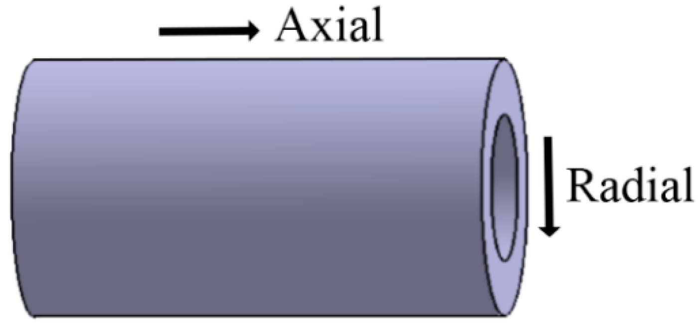
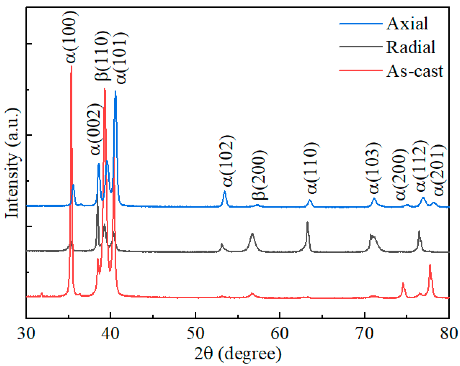
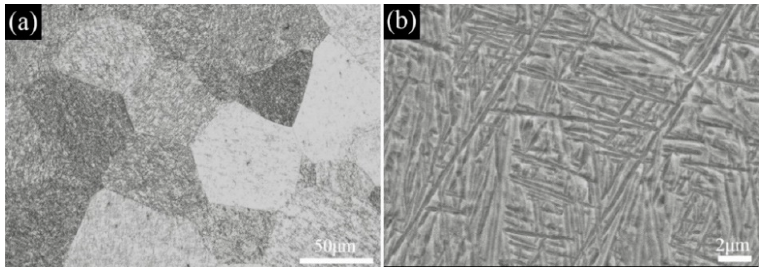
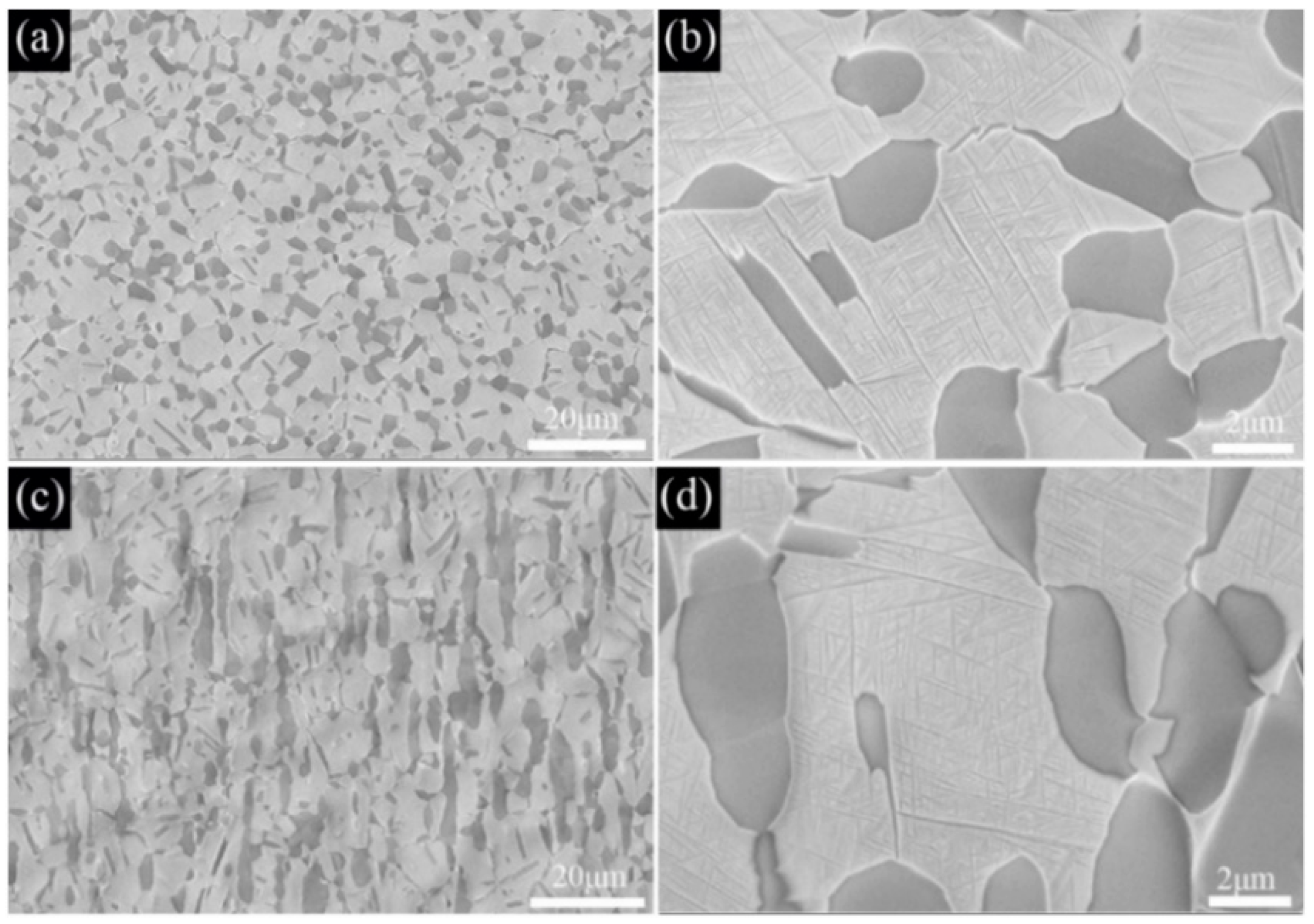
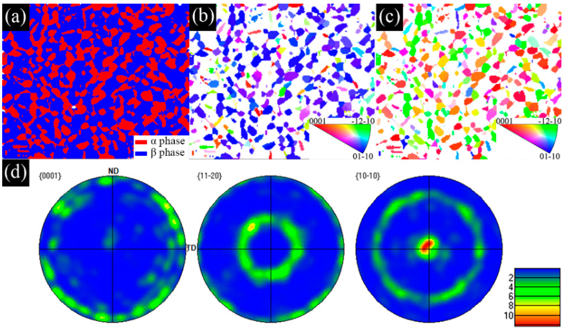
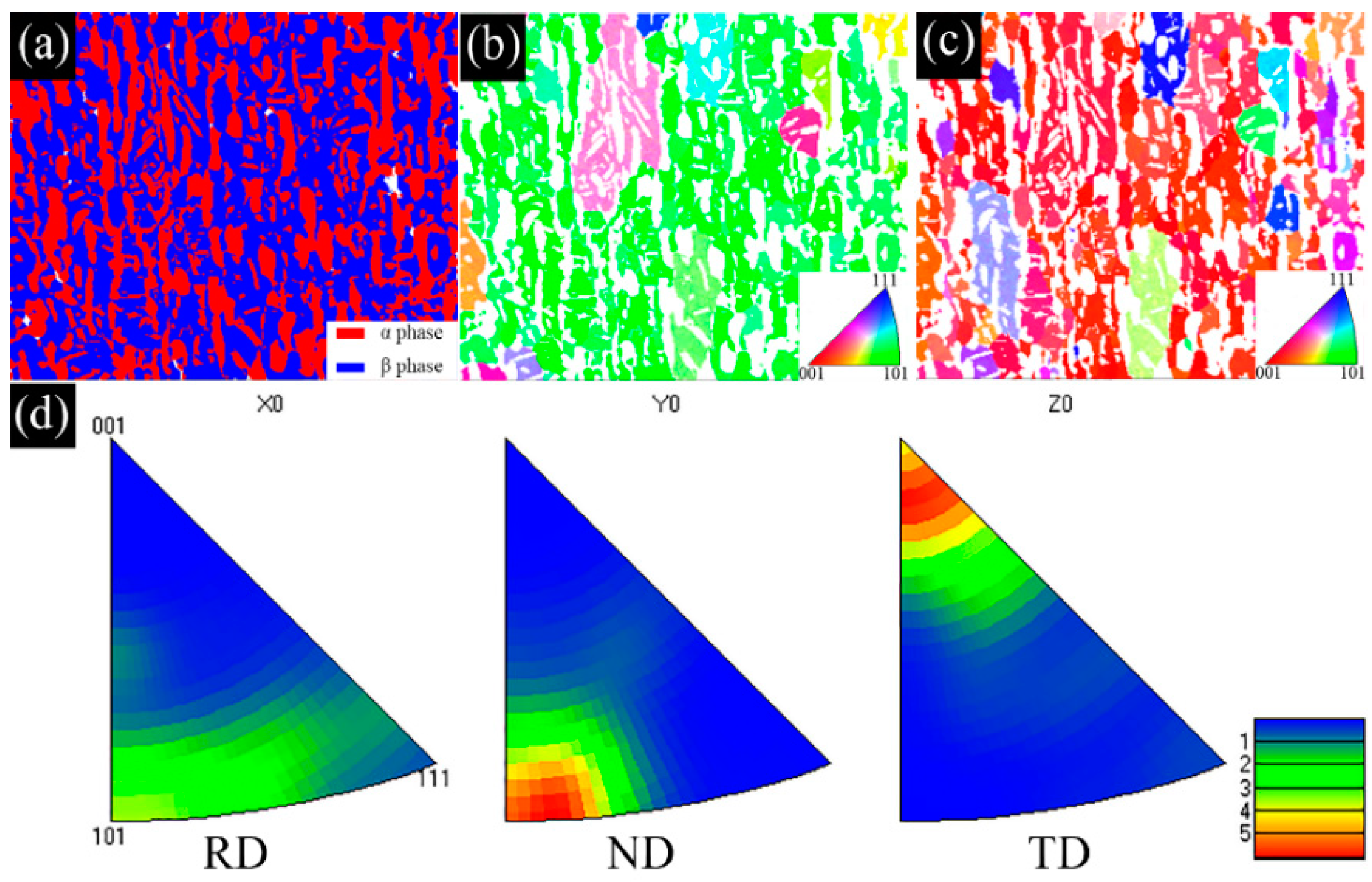
The as−extruded Ti−6Al−3Mo−2Zr−2Fe alloy exhibited a typical (α + β) duplex microstructure. The α + β phases exhibited a flat strip shape in the axial direction due to the effect of the external force during the extrusion process. The strong < 10   1 ¯ 0 > fiber texture of the α phase was formed in the radial direction. The mixed texture of the <101>//ND and <001>//TD of the β phase was formed in the axial direction.
(2)
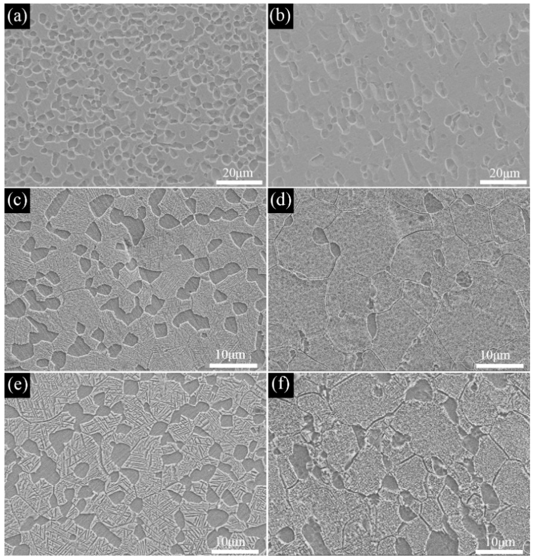
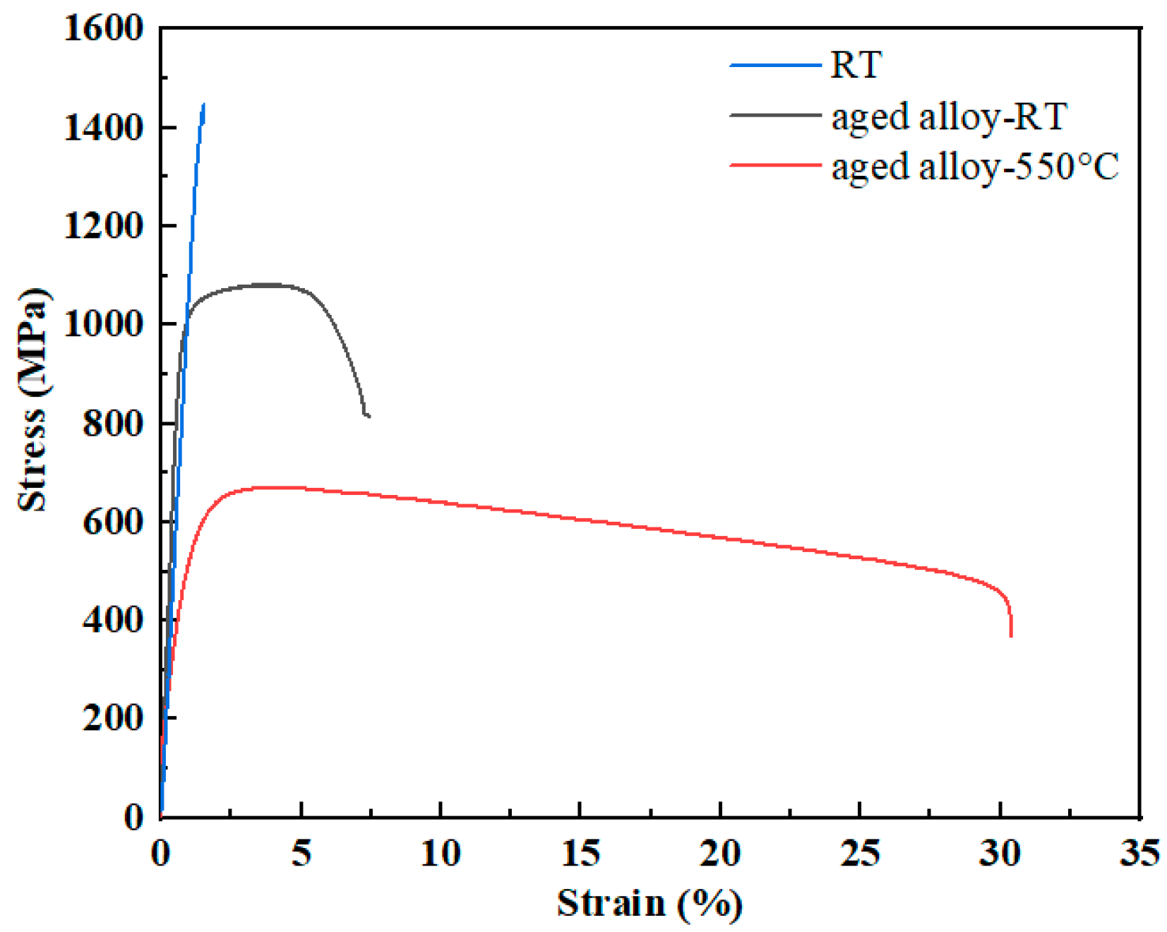
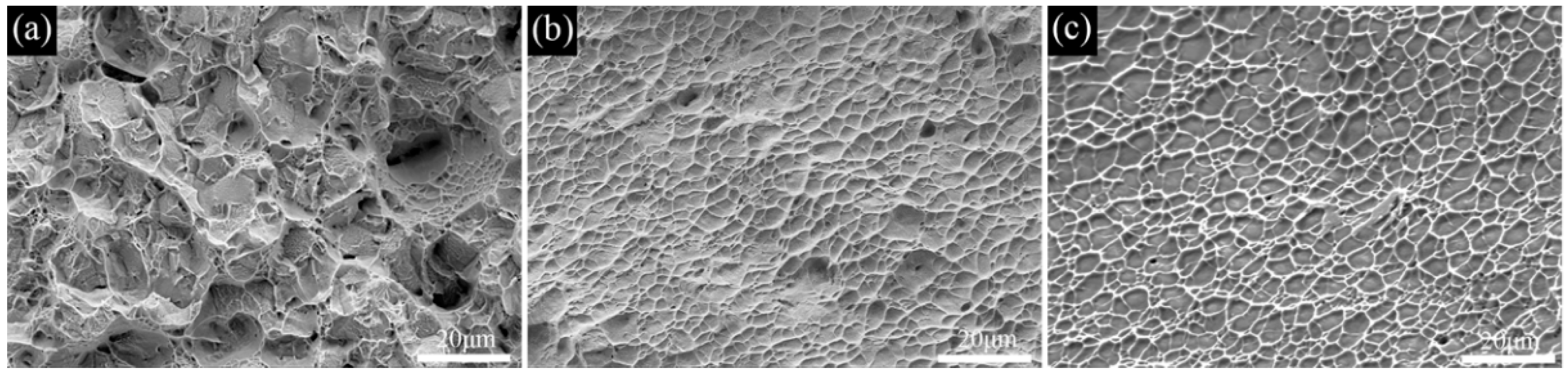
The transformation temperature Tβ of the Ti−6Al−3Mo−2Zr−2Fe alloy was determined to be 880–890 °C using the metallographic method. When the alloy was solution−treated at 850 °C for 1h and underwent an aging treatment at 550 °C for 6 h, the alloy exhibited excellent mechanical properties. The room−temperature tensile strength and elongation of the alloy were 1081.5 MPa and 6.5%, respectively. The fracture morphology showed a classic dimple shape.
(3)
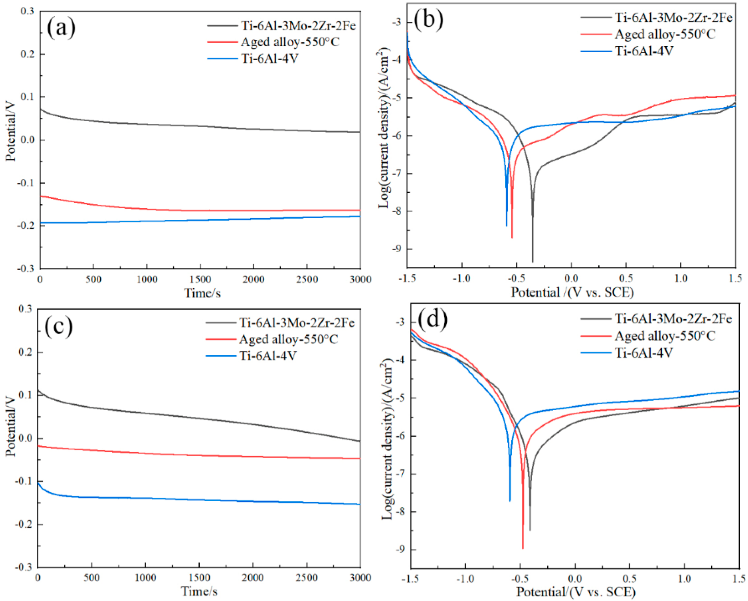
The corrosion current densities of the aged Ti−6Al−3Mo−2Zr−2Fe alloy in a 3.5% NaCl solution and an acidic solution were 1.7 × 10⁻⁷ A/cm2 and 6.7 × 10⁻⁷ A/cm2, respectively, which were lower than those of the TC4 alloy. This indicated that the corrosion resistance of the Ti−6Al−3Mo−2Zr−2Fe alloy was better than that of TC4 in both the 3.5%NaCl and acidic solutions, which was related to the alloying elements. The addition of Mo promoted the formation of a passivation film on the alloy surface. The addition of Zr improved the chemical dissolution resistance of the TiO2 passivation film.

Author Contributions

Conceptualization, N.C. and methodology, H.N. and W.S.; software, S.C.; validation, S.C., W.S. and B.L.; formal analysis, T.X.; investigation, S.Z.; resources, N.C.; data curation, S.C. and T.X.; writing—original draft preparation, N.C. and S.C.; writing—review and editing, S.C. and T.X.; visualization, S.C.; supervision, F.K.; project administration, N.C.; funding acquisition, N.C. All authors have read and agreed to the published version of the manuscript.

Funding

This work was supported by the National Natural Science Foundation of China (No. 51704174, 52271026) and the Key Research and development program of Shandong province (No. 2019GGX102045).

Institutional Review Board Statement

Not applicable.

Informed Consent Statement

Not applicable.

Data Availability Statement

Not applicable.

Acknowledgments

The authors would like to acknowledge the support of the National Natural Science Foundation of China (No. 51704174, 52271026) and the Key Research and development program of Shandong province (No. 2019GGX102045).

Conflicts of Interest

The authors declare that they have no known competing financial interests or personal relationships that could have appeared to influence the work reported in this paper.

References

  1. Pushp, P.; Dasharath, S.; Arati, C. Classification and applications of titanium and its alloys. Mater. Today Proc. 2022, 54, 537–542. [Google Scholar] [CrossRef]
  2. Liu, S.; Song, X.; Xue, T.; Ma, N.; Wang, Y.; Wang, L. Application and development of titanium alloy and titanium matrix composites in aerospace field. J. Aeronaut. Mater. 2020, 40, 77–94. [Google Scholar] [CrossRef]
  3. Williams, J.C.; Boyer, R.R. Opportunities and issues in the application of titanium alloys for aerospace components. Metals 2020, 10, 705. [Google Scholar] [CrossRef]
  4. Tshephe, T.S.; Akinwamide, S.O.; Olevsky, E.; Olubambi, P.A. Additive manufacturing of titanium-based alloys—A review of methods, properties, challenges, and prospects. Heliyon 2022, 8, e09041. [Google Scholar] [CrossRef]
  5. Peters, M.; Kumpfert, J.; Ward, C.H.; Leyens, C. Titanium alloys for aerospace applications. Adv. Eng. Mater. 2003, 5, 419–427. [Google Scholar] [CrossRef]
  6. Yingli, Y.; Yuanyuan, L.; Hengzhang, Z.; Dizi, G.; Jinping, W.; Hangbiao, S.; Bin, Z. Research and application status of titanium alloys for marine engineering. Titan. Ind. Prog. 2022, 39, 43–48. [Google Scholar] [CrossRef]
  7. Yan, S.; Song, G.L.; Li, Z.; Wang, H.; Zheng, D.; Cao, F.; Horynova, M.; Dargusch, M.; Zhou, L. A state-of-the-art review on passivation and biofouling of Ti and its alloys in marine environments. J. Mater. Sci. Technol. 2018, 34, 421–435. [Google Scholar] [CrossRef]
  8. Li, R.Z.; Feng, C.; Jiang, L.; Cao, Y.Q. Research status and development of titanium alloy drill pipes. Mater. Sci. Fourm 2019, 944, 903–909. [Google Scholar] [CrossRef]
  9. Wang, C.P.; Wang, H.Z.; Ruan, G.L.; Wang, S.H.; Xiao, Y.X.; Jiang, L.D. Applications and prospects of titanium and its alloys in seawater desalination industry. IOP Conf. Ser. Mater. Sci. Eng. A 2019, 688, 033036. [Google Scholar] [CrossRef]
  10. Nasad, T.G.; Kochetkov, A.V. Highly Efficient Methods of Machining Titanium for Oil-Gas Drilling Equipment. Chem. Pet. Eng. 2016, 52, 227–230. [Google Scholar] [CrossRef]
  11. Gorynin, I.V. Titanium alloys for marine application. Mater. Sci. Eng. A 1999, 263, 112–116. [Google Scholar] [CrossRef]
  12. Bania, P.J. Beta titanium alloys and their role in the titanium industry. JOM 1994, 46, 16–19. [Google Scholar] [CrossRef]
  13. Rosenberg, H.W. Titanium alloying in theory and practice. In The Science, Technology and Application of Titanium; Elsevier: Amsterdam, The Netherlands, 1970; pp. 851–859. [Google Scholar]
  14. Xu, W.; Chen, M.; Lu, X.; Zhang, D.W.; Singh, H.P.; Jian Shu, Y.; Pan, Y.; Qu, X.-H.; Liu, C.Z. Effects of Mo content on corrosion and tribocorrosion behaviours of Ti-Mo orthopaedic alloys fabricated by powder metallurgy. Corros. Sci. 2020, 168, 108557. [Google Scholar] [CrossRef]
  15. Yu, S.Y.; Brodrick, C.W.; Ryan, M.P.; Scully, J.R. Effects of Nb and Zr Alloying Additions on the Activation Behavior of Ti in Hydrochloric Acid. J. Electrochem. Soc. 1999, 146, 4429–4438. [Google Scholar] [CrossRef]
  16. Song, Y.; Xu, D.; Yang, R.; Li, D.; Wu, W.; Guo, Z. Theoretical study of the effects of alloying elements on the strength and modulus of β-type bio-titanium alloys. Mater. Sci. Eng. A 1999, 260, 269–274. [Google Scholar] [CrossRef]
  17. Kuroda, D.; Kawasaki, H.; Yamamoto, A.; Hiromoto, S.; Hanawa, T. Mechanical properties and microstructures of new Ti-Fe-Ta and Ti-Fe-Ta-Zr system alloys. Mater. Sci. Eng. C 2005, 25, 312–320. [Google Scholar] [CrossRef]
  18. Liu, Y.; Chen, L.F.; Tang, H.P.; Liu, C.T.; Liu, B.; Huang, B.Y. Design of powder metallurgy titanium alloys and composites. Mater. Sci. Eng. A 2006, 418, 25–35. [Google Scholar] [CrossRef]
  19. Ma, X.; Xiang, Z.; Ma, M.; Cui, Y.; Ren, W.; Wang, Z.; Huang, J.; Chen, Z. Investigation of microstructures, textures, mechanical properties and fracture behaviors of a newly developed near α titanium alloy. Mater. Sci. Eng. A 2020, 775, 138996. [Google Scholar] [CrossRef]
  20. Ding, C.; Liu, C.; Zhang, L.; Deng, Y.; Liu, H.; Wu, D.; Liu, L. Microstructure and tensile properties of a cost-affordable and ultrahigh-strength metastable β titanium alloy with a composition of Ti-6Al-1Mo-1Fe-6.9Cr. J. Alloys Compd. 2022, 901, 163476. [Google Scholar] [CrossRef]
  21. Wen, X.; Wan, M.; Huang, C.; Lei, M. Strength and fracture toughness of TC21 alloy with multi-level lamellar microstructure. Mater. Sci. Eng. A 2018, 740, 121–129. [Google Scholar] [CrossRef]
  22. Wang, T.; Guo, H.; Wang, Y.; Yao, Z. Influence of processing parameters on microstructure and tensile properties of TG6 titanium alloy. Mater. Sci. Eng. A 2010, 528, 736–744. [Google Scholar] [CrossRef]
  23. Zhang, X.; Jia, W.; Mao, X. Effect of microstructure on the tensile properties and impact toughness of TC21G titanium alloy. Mater. Charact. 2022, 185, 111752. [Google Scholar] [CrossRef]
  24. Li, C.L.; Mi, X.J.; Ye, W.J.; Hui, S.X.; Yu, Y.; Wang, W.Q. A study on the microstructures and tensile properties of new beta high strength titanium alloy. J. Alloys Compd. 2013, 550, 23–30. [Google Scholar] [CrossRef]
  25. Chen, Z.; Xu, L.; Liang, Z.; Cao, S.; Yang, J.; Xiao, S.; Tian, J.; Chen, Y. Effect of solution treatment and aging on microstructure, tensile properties and creep behavior of a hot-rolled β high strength titanium alloy with a composition of Ti-3.5Al-5Mo-6V-3Cr-2Sn-0.5Fe-0.1B-0.1C. Mater. Sci. Eng. A 2021, 823, 141728. [Google Scholar] [CrossRef]
  26. Du, Z.; Guo, H.; Liu, J.; Cheng, J.; Zhao, X.; Wang, X.; Liu, F.; Cui, X. Microstructure evolution during aging heat treatment and its effects on tensile properties and dynamic Young’s modulus of a biomedical β titanium alloy. Mater. Sci. Eng. A 2020, 791, 139677. [Google Scholar] [CrossRef]
  27. Narayana, P.; Kim, S.W.; Hong, J.K.; Reddy, N.; Yeom, J.T. Tensile properties of a newly developed high−temperature titanium alloy at room temperature and 650 °C. Mater. Sci. Eng. A 2018, 718, 287–291. [Google Scholar] [CrossRef]
  28. Jin, W.; Feng, K.; Li, Z.; Cai, X.; Yu, L.; Zhou, D. Improvement of corrosion resistance and electrical conductivity of 304 stainless steel using close field unbalanced magnetron sputtered carbon film. Power Sources 2011, 196, 10032–10037. [Google Scholar] [CrossRef]
  29. Li, Q.; Chen, K.; Xia, C.; Chen, B.; Liu, S.; Yang, T.; Liu, D.; Wang, Y.; Zhang, X. Microstructure evolution, mechanical properties, and corrosion behavior of novel Zr-Ti-V alloys. Mater. Sci. Eng. A 2021, 817, 141358. [Google Scholar] [CrossRef]
  30. Zhang, M.; Hu, L.; Lin, G.; Shao, Z. Honeycomb−like nanocomposite Ti-Ag-N films prepared by pulsed bias arc ion plating on titanium as bipolar plates for unitized regenerative fuel cells. Power Sources 2012, 198, 196–202. [Google Scholar] [CrossRef]
  31. Chui, P.; Jing, R.; Zhang, F.; Li, J.; Feng, T. Mechanical properties and corrosion behavior of β-type Ti-Zr-Nb-Mo alloys for biomedical application. J. Alloys Compd. 2020, 842, 155693. [Google Scholar] [CrossRef]
  32. Su, B.; Luo, L.; Wang, B.; Su, Y.; Wang, L.; Ritchie, R.O.; Guo, E.; Li, T.; Yang, H.; Huang, H.; et al. Annealed microstructure dependent corrosion behavior of Ti-6Al-3Nb-2Zr-1Mo alloy. J. Mater. Sci. Technol. 2021, 62, 234–248. [Google Scholar] [CrossRef]
  33. Kong, D.S.; Feng, Y.Y. Electrochemical Anodic Dissolution Kinetics of Titanium in Fluoride-Containing Perchloric Acid Solutions at Open-Circuit Potentials. J. Electrochem. Soc. 2009, 156, C283. [Google Scholar] [CrossRef]
  34. Atapour, M.; Pilchak, A.; Frankel, G.; Williams, J. Corrosion behavior of β titanium alloys for biomedical applications. Mater. Sci. Eng. C 2011, 31, 885–891. [Google Scholar] [CrossRef]
Figure 1. Schematic diagram of the extruded Ti−6Al−3Mo−2Zr−2Fe alloy tube.
Metals 12 01564 g001
Figure 2. XRD spectra of Ti−6Al−3Mo−2Zr−2Fe.
Metals 12 01564 g002
Figure 3. The microstructure of the as−cast Ti−6Al−3Mo−2Zr−2Fe alloy. (a) Optical image, (b) SEM image.
Metals 12 01564 g003
Figure 4. SEM images of the as−extruded Ti−6Al−3Mo−2Zr−2Fe alloy. (a,b) Radial, (c,d) axial.
Metals 12 01564 g004
Figure 5. EBSD maps of the as−extruded Ti−6Al−3Mo−2Zr−2Fe alloy in the radial direction. (a) Phase distribution map, (b) OIM map in the RD direction, (c) OIM map in the TD direction, (d) Pole figure.
Metals 12 01564 g005
Figure 6. EBSD maps of the extruded Ti−6Al−3Mo−2Zr−2Fe alloy in the axial direction. (a) Phase distribution map, (b) OIM map in the RD direction, (c) OIM map in the TD direction, (d) Inverse pole figure.
Metals 12 01564 g006
Figure 7. Solution and aging treatment images (left radial, right axial). (a,b) 850°C solution treatment; (c,d) 550 °C aging treatment; (e,f) 600 °C aging treatment.
Metals 12 01564 g007
Figure 8. Stress–strain curve of Ti−6Al−3Mo−2Zr−2Fe.
Metals 12 01564 g008
Figure 9. Tensile fracture morphology of Ti−6Al−3Mo−2Zr−2Fe alloy. (a) as−extruded−RT, (b) aged alloy−RT, (c) aged alloy−500 °C.
Metals 12 01564 g009
Figure 10. Electrochemical tests of the extruded and aged Ti−6Al−3Mo−2Zr−2Fe alloy. (a) Open circuit potential in 3.5% NaCl solution; (b) potentiodynamic polarization curves in 3.5% NaCl solution; (c) open circuit potential in acid solution; (d) potentiodynamic polarization curves in acid solution.
Metals 12 01564 g010
Table 1. Corrosion potential and corrosion current density of Ti−6Al−3Mo−2Zr−2Fe and TC4 alloys.
SolutionParametersTAMZF550 °CTC4
3.5%NaClEcorr (V)−0.35−0.55−0.60
icorr (A/cm2)1.4 × 10−71.7 × 10−75.3 × 10⁻⁷
H2SO4 + HFEcorr (V)−0.42−0.48−0.61
icorr (A/cm2)2.7 × 10−76.7 × 10−71.8 × 10⁻⁶
Publisher’s Note: MDPI stays neutral with regard to jurisdictional claims in published maps and institutional affiliations.

