Article

Galvanic Corrosion Study between Tensile-Stressed and Non-Stressed Carbon Steels in Simulated Concrete Pore Solution

1
College of Civil Engineering, Zhejiang University of Technology, Hangzhou 310023, China
2
Key Laboratory of Performance Evolution and Control for Engineering Structures (Tongji University), Ministry of Education, Shanghai 200092, China
3
Glenn Department of Civil Engineering, Clemson University, Clemson, SC 29634, USA
4
Department of Materials Science and Engineering, Clemson University, Clemson, SC 29634, USA
*
Author to whom correspondence should be addressed.
Metals 2022, 12(1), 98; https://doi.org/10.3390/met12010098
Submission received: 23 November 2021 / Revised: 31 December 2021 / Accepted: 2 January 2022 / Published: 4 January 2022

Abstract

:
The present study investigated the galvanic effect between tensile-stressed and non-stressed carbon steels, in addition to the influence of the tensile stress on the passivation and corrosion behavior of steel in a simulated concrete pore solution. Three different levels of tensile stress, ranging from elastic to plastic stress on the surface, were applied by adjusting the displacement of C-shape carbon steel rings. Different electrochemical measurements including the open circuit potential (OCP), the electrochemical impedance spectroscopy (EIS), the zero-resistance ammetry (ZRA), and the cyclic polarization were performed. Based on the results of EIS, the tensile stress degraded the resistance of the oxide film in moderate frequencies while enhancing the charge transfer resistance in low frequencies during passivation. As corrosion propagated, the stressed steel yielded a similar charge transfer resistance to or an even lower charge transfer resistance than the non-stressed steel, especially in the case of plastic tensile stress. The galvanic effect between the tensile-stressed and non-stressed steels increased the chloride threshold value of the tensile-stressed steel, although the susceptibility to pitting corrosion was exhibited after being corroded.

1. Introduction

Reinforcing steel in concrete structures is vulnerable to the attack of environmental factors including chemicals such as chlorides [1,2] and temperature [3,4,5]. In addition, external stress escalates the penetration of aggressive agents due to the formation of damage at aggregate/paste interfaces (i.e., continuous microcracks), thereby degrading the performance of concrete [6,7,8]. Stress also influences the corrosion activity of steel, regardless of the damage in concrete [9,10,11,12,13]. According to the mechano-electrochemical interaction, the corrosion thermodynamics and kinetics can be altered under stress, possibly due to localized lattice distortion and higher activation energy [14,15,16].
With respect to steel in the alkaline environment of concrete, a passive film forms on the surface of steel. The applied tensile stress may induce microcracks in the passive oxide film of steel [17,18,19], while compressive stress may lead to the debonding between the passive film and the substrate steel [19]. Thus, the passivation of steel under stress may be subjected to the synergistic effect of mechanical damage in the passive film and the mechano-electrochemical oxidation activity of steel. Zhang and Poursaee [11] have found that a more protective passive film forms on the surface of steel under tensile stress, compared to that of compressive-stressed and non-stressed steels in a chloride-free concrete pore solution. The enhancement on the passivation behavior of tensile-stressed steel in concrete has also been evidenced by Behera et al. [16]. Once steels are exposed to a chloride-contaminated concrete pore solution after the initial formation of a passive film, steel under tensile stress corrodes faster than those under compressive stress and no stress. The aggravation of the oxidation rate under tensile stress in an aggressive environment has also been evidenced in metals other than in steels [20,21,22]. With respect to the effect of compressive stress, stressed steel shows better performance than those under no loading conditions when exposed to the chloride-laden environment [10,11].
Various types and levels of stress alter the corrosion behavior of steels in concrete structures. In this regard, galvanic corrosion occurs, which typically exists between metals with different corrosion activities [23,24,25,26,27,28] or between dissimilar phases in the microstructure of a metal [29]. Galvanic corrosion can be detrimental in concrete. The galvanic coupling between different portions of reinforcing steel subjected to different types of stress in a concrete environment can form. The corrosion of the more active part of steel can be further aggravated, while the less active portion is protected due to the galvanic effect. To the author’s knowledge, there has been, so far, no study on this subject, which is the objective of this study.

2. Experimental Procedures

C-shape specimens have been widely used in evaluating the stress corrosion of metals [10,11,30,31], which were utilized in this study. As shown in Figure 1, the exposed area in a C-shape carbon steel specimen was the area experiencing the largest value of the tensile stress. By adjusting the displacement for the length of the rod (H), different levels of the tensile stress were achieved. The displacement of HH) and the corresponding tensile stress were calculated through ANSYS finite element simulation in previous studies, and the results are shown in Table 1 [10,11].
C-shape carbon steel specimens were prepared by cutting 20-mm sections from a general-purpose, unpolished, hot-rolled carbon steel tube, with chemical compositions listed in Table 2 [11]. The inner and outer diameters of the steel tube were 98.30 mm (3.87 in.) and 101.60 mm (4 in.), respectively. A length of 25.40 mm (1 in.) was cut from the welded area of the tube to make the C-shape specimen, allowing for the adjustment of displacement of H. A high-strength fiberglass threaded rod and nut were employed to control the displacement and, consequently, the tensile stress on the exposed surface of steel specimens. A copper wire was connected to each specimen, providing electrical connection for electrochemical tests. Afterwards, 3 layers of epoxy resin were coated on the surfaces of the specimens exclusive of the exposed area, as depicted in Figure 1. Two sets of the specimens were designed: (i) individual specimens, containing the stress level of (σy) of 0%, 33%, 55%, and 110% of yield stress (σy), denoted as A0, A3, A5, and A10, respectively; and (ii) coupled specimens, denoted as C, including coupled non-stressed steel (0% of σy) with stressed steels with 33%, 55%, and 110% of σy, denoted as C3, C5, and C10, respectively. To ensure the reproducibility of the experimental results, three identical specimens were prepared in each individual and coupled set.
A simulated concrete pore solution (SCPS) was used as an electrolyte to simulate the concrete environment. The composition shown in Table 3 was based on the pore solution extraction from cement samples with a water/cement ratio of 0.42 [32,33]. All specimens were immersed in a chloride-free pore solution for 30 days. Then, 3 wt % of laboratory-grade NaCl was added to each measurement cell. To further accelerate the corrosion activity, the concentration of NaCl was increased to 10 wt % after 53 days of exposure to the solution. During the experiment, the pH of the pore solution in each measurement cell was periodically measured to ascertain a value of 13.1. The pH level was adjusted periodically by the partial refreshment of the pore solution with a fresh solution. The measurement cells were sealed during the experiment to minimize the atmospheric carbonation effect and evaporation.
The open circuit potential (OCP) values of specimens were measured every 3 days, using a saturated calomel electrode (SCE) as the reference electrode. Before each measurement, the OPC was measured, until the stabilized value reached, generally around 10 min. The electrochemical impedance spectroscopy (EIS) technique was employed to investigate the passivation and corrosion characteristics of both individual specimens and specimens involved in the coupled cells. Prior to the performance of EIS for tensile-stressed steels in the coupled cells, the tensile-stressed steel was disconnected to the non-stressed steel for 30 min to stabilize the potential. A 10 mV alternating sinusoidal potential perturbation vs. an OCP over the frequency range of 105 Hz to 10−2 Hz were used for the EIS tests. EIS is informative and provides quantitative results of passivation and corrosion properties with respect to the double-layer capacitance, the charge transfer resistance, as well as the electrolyte resistance, etc. [3,4,5,34,35]. To evaluate the susceptibility of the specimens to pitting corrosion, the cyclic polarization (CP) technique was conducted on both individual and disconnected specimens. All the CP tests were conducted starting from −200 mV vs. OCP, increased to +500 mV vs. SCE and then decreased to −200 mV vs. OCP, at a scan rate of 0.166 mV/s [36]. The EIS and CP tests were carried out through a three-electrode measurement setup, including a steel specimen as the working electrode, an SCE as the reference electrode, and a 316L stainless steel as the counter electrode. The galvanic current between the coupled stressed and non-stressed steels was measured by using the zero-resistance ammetry (ZRA) technique. The galvanic current was measured for 30 min each time, every 3 days. All the electrochemical measurements were conducted at the ambient temperature (23 °C).

3. Results

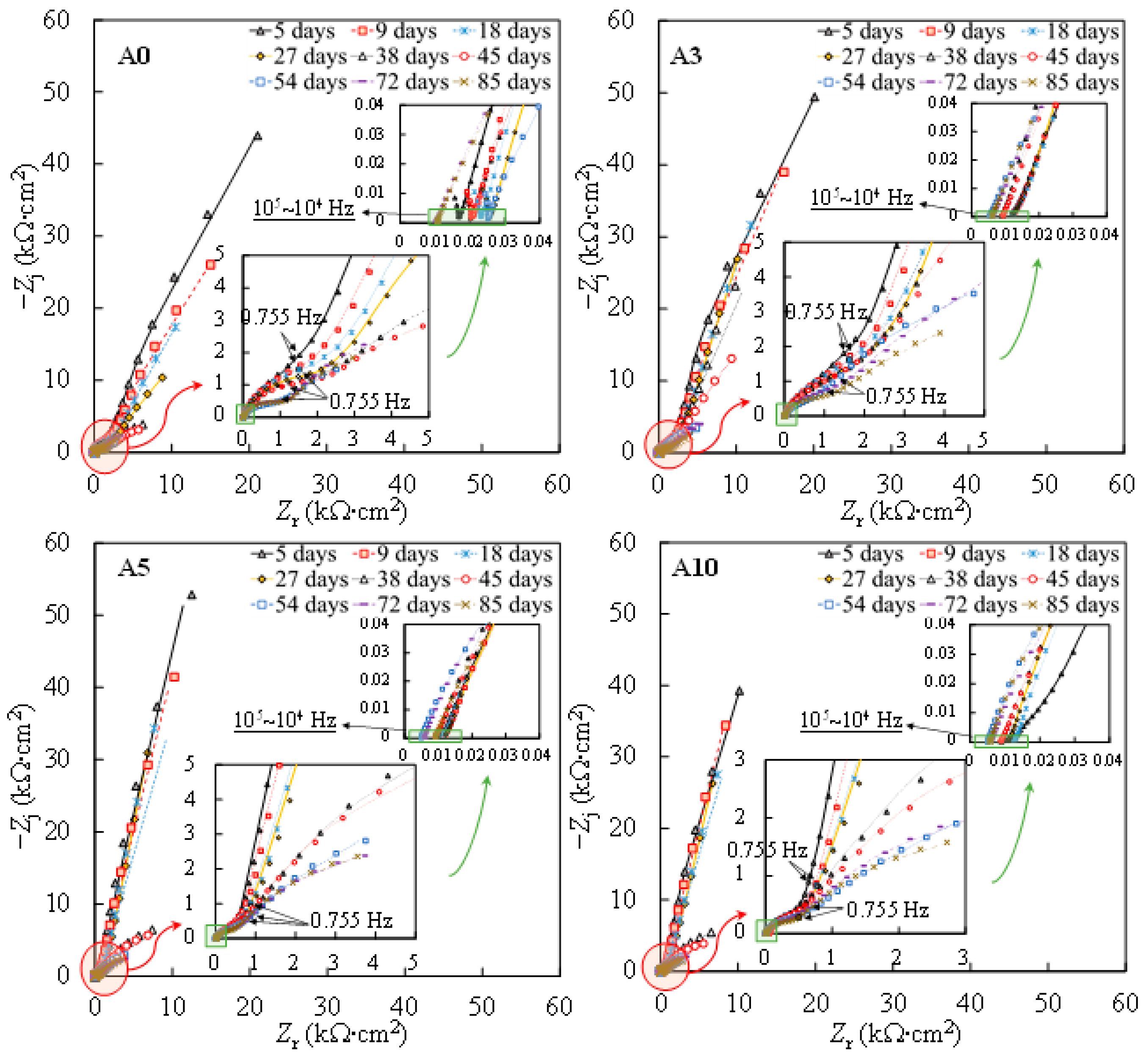
Figure 2 shows the Nyquist plots from the EIS measurements on one of the steel samples subjected to each level of tensile stress. To better interpret the EIS plots, the impedance modulus and the phase angle denoted as φadj and |Z|adj, respectively, were adjusted to discard the influence of the solution ohmic resistance according to Equations (1) and (2), respectively [37,38]:
φ adj = tan 1 ( Z j Z r R s ) ,
| Z | adj = ( Z r R s ) 2 + Z j 2 ,
where Zj is the imaginary part of the impedance, Zr is the real part of the impedance, and Rs is the solution resistance obtained from the asymptotic value of Zr at high frequencies.
During the passivation of steel in the SCPS, Fe was firstly oxidized to form compounds of Fe(II) and Fe(III) oxides via Equations (3)–(6) [39]:
Fe + OH = [ Fe ( OH ) ] ads + e ,
[ Fe ( OH ) ] ads = [ Fe ( OH ) ] ads + + e ,
[ Fe ( OH ) ] ads + + OH = Fe ( OH ) 2 ,
3 Fe ( OH ) 2 + 2 OH = Fe 3 O 4 + 4 H 2 O + 2 e .
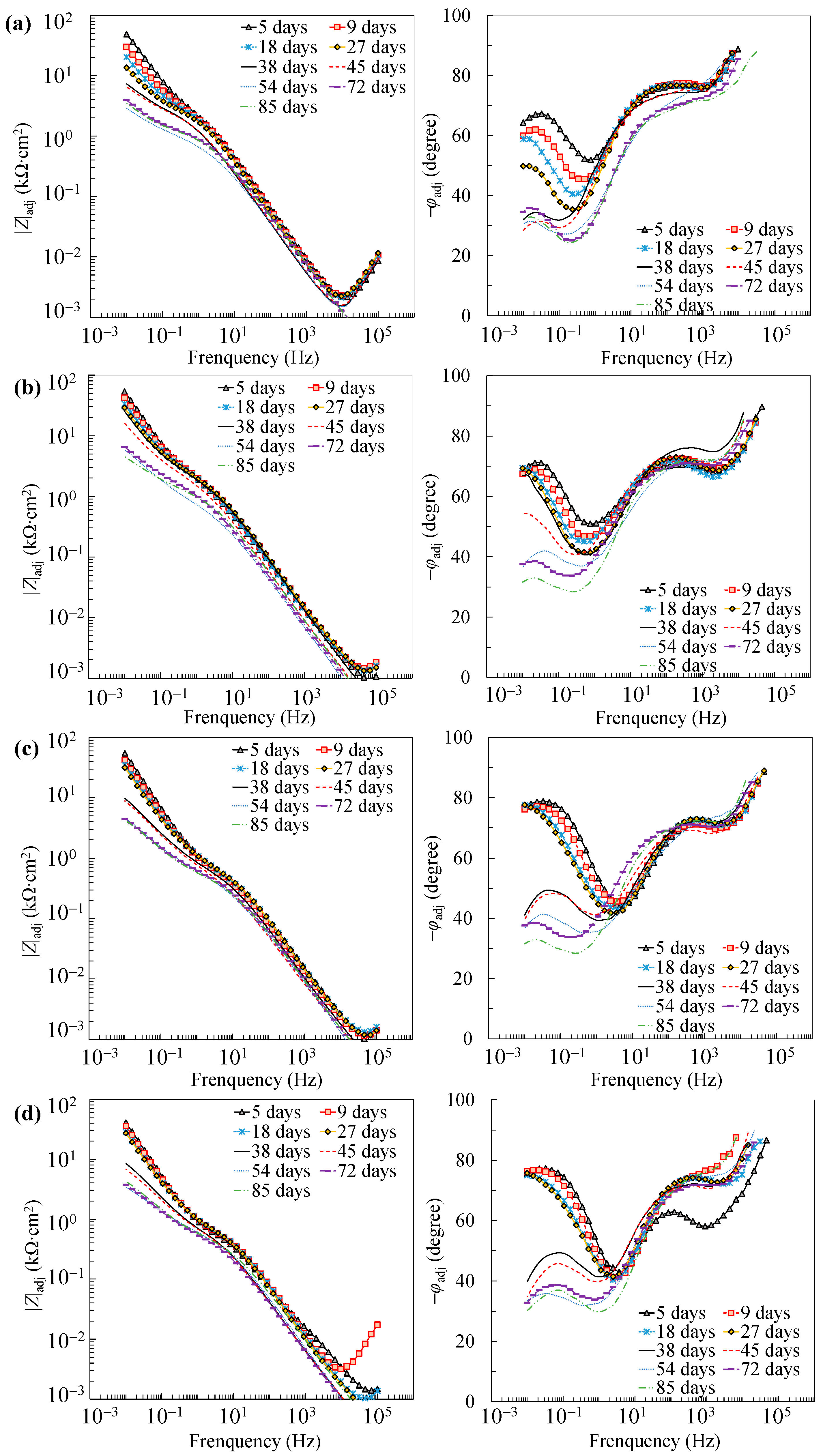
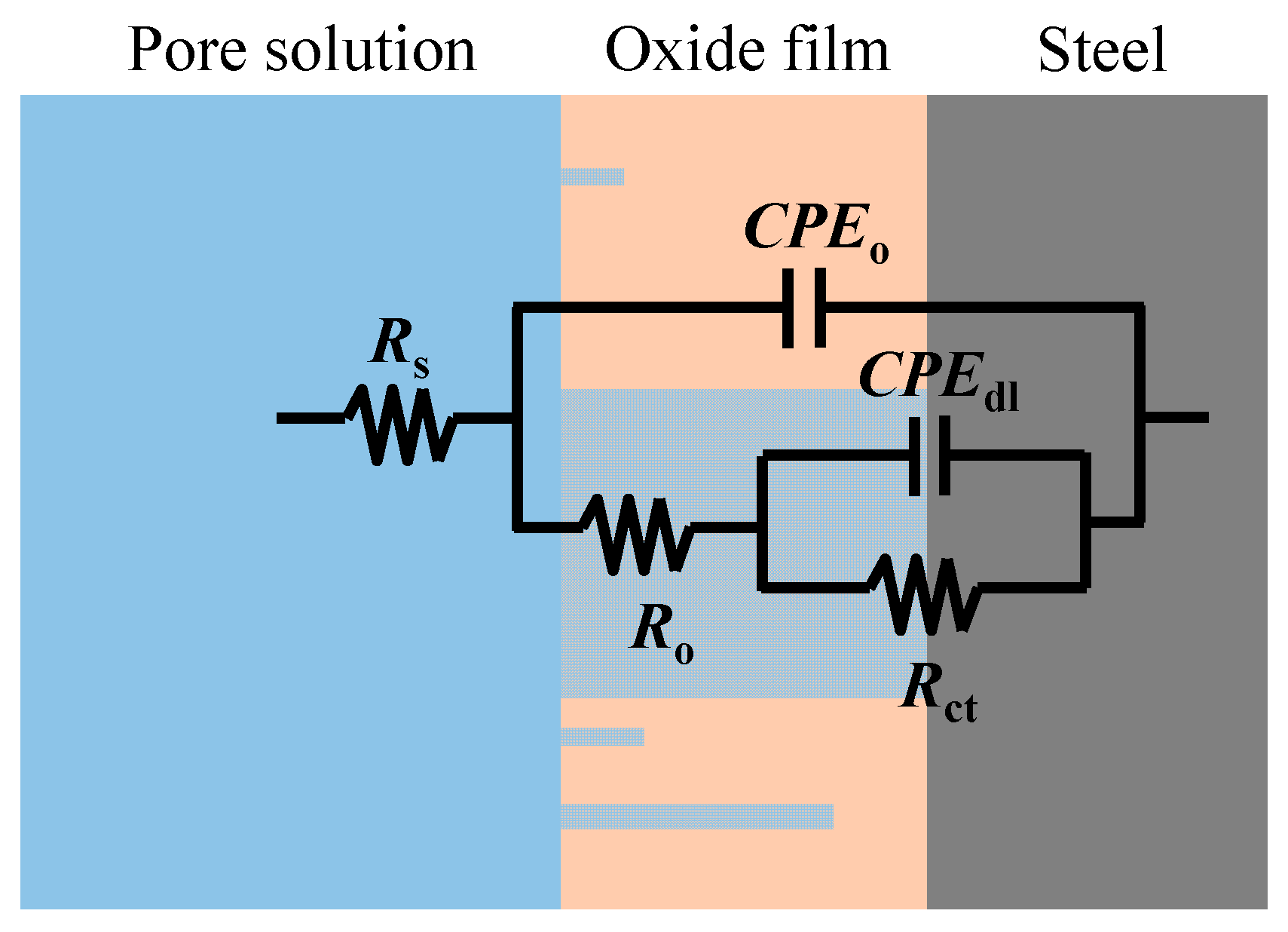
Further reaction for the generation of FeOOH could occur, leading to a porous oxide film formed on the surface of carbon steel in a high-alkaline solution [40,41,42]. In this regard, two depressed arcs were observed in the Nyquist plot during the passivation stage (i.e., results prior to 38 days in Figure 2). The solution resistance was determined as the real impedance (Zr) at the point where the semicircle at high frequencies intersects the x-axis or occupies the lowest value of the imaginary impedance (—Zj) through the Nyquist plot (i.e., 105–104 Hz shown in the magnified region in Figure 2). The frequencies in the range of 10 Hz to 100 Hz were ascribed to the dielectric properties of the oxide film/solution. Frequencies lower than 1 Hz were attributed to the dielectric properties of the metal/solution interface, where there are defects or pores in the oxide film in the absence of chloride, and active corroding areas in the presence of chlorides. Figure 3 shows the Bode plots of the EIS measurements. It should be noted that the dispersion in the frequency range higher than ~10 kHz shown in the adjusted Bode phase plot (Figure 3) was possibly caused by the geometric effect of the electrode in terms of the current and potential distributions or the distributed thickness of the passive oxide film [43,44,45]. Equivalent circuit shown in Figure 4 was used to fit the EIS data. Rs represents the solution resistance. The resistance to the current flow through defects or pores in the oxide film is denoted as Ro, while the CPEo represents the capacitive response of the oxide film. The Rct and CPEdl in Figure 4 represent the charge transfer resistance and the interfacial capacitance, respectively, corresponding to the faradaic reactions.
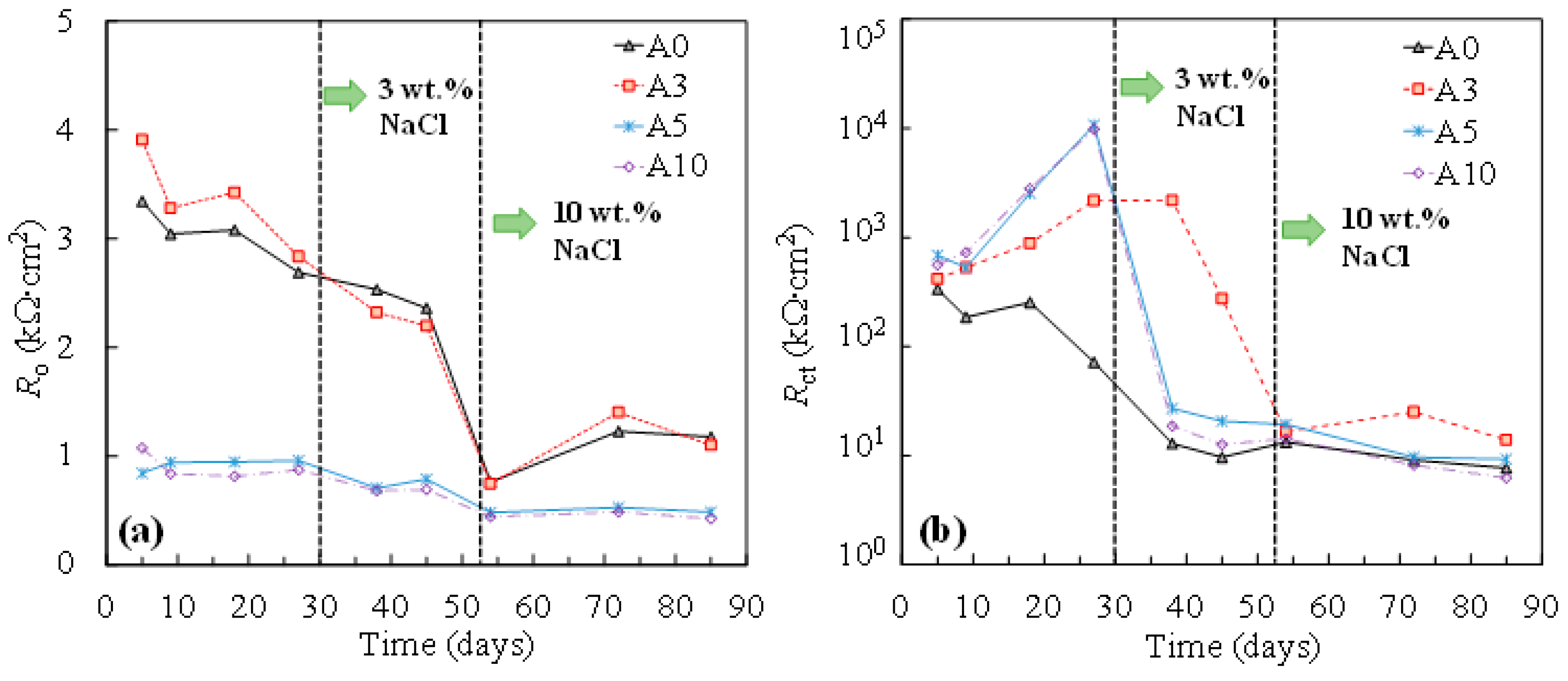
The results of the changes in the resistance of the oxide film (Ro) and the resistance of the charge transfer (Rct) by time, obtained from fitting the equivalent circuit in Figure 4, are shown in Figure 5. As can be seen, with the addition of chlorides, both Ro and Rct decreased in all cases. Compared to for non-stressed steel (A0), little influence was exhibited for the resistance of the passive oxide film when the tensile stress was low (i.e., σy of 33% in this study). Interestedly, as the tensile stress increased, a considerable reduction in the Ro during passivation was demonstrated (Figure 5a). As the tensile stress increased, the increment in Rct during passivation was observed, compared to that of the non-stressed one (Figure 5b). According to the literature, tensile stress can induce microcracks in the passive film [17]. It is hypothesized that more defective surfaces provide more free surfaces for repassivation reactions. In this regard, a more protective passive film formed on the surface of the tensile-stressed specimens, demonstrating a higher value of Rct compared to that of the non-stressed one.
After the addition of chlorides, the charge transfer resistance of tensile-stressed steels underwent a cliff-like drop and eventually yielded a similar or even lower value of Rct compared to that of the non-stressed steel (A0), especially in the case of plastically stressed steel (A10). It was also evidenced by the results of corrosion potential shown in Figure 6. In the chloride-free SCPS, tensile-stressed steels exhibited a more positive potential than that of the non-stressed steels (A0). After the addition of chlorides, steels under low tensile stress (i.e., A3) showed a similar potential with non-stressed specimens (A0), while A5 and A10 demonstrated a more negative potential than A0.
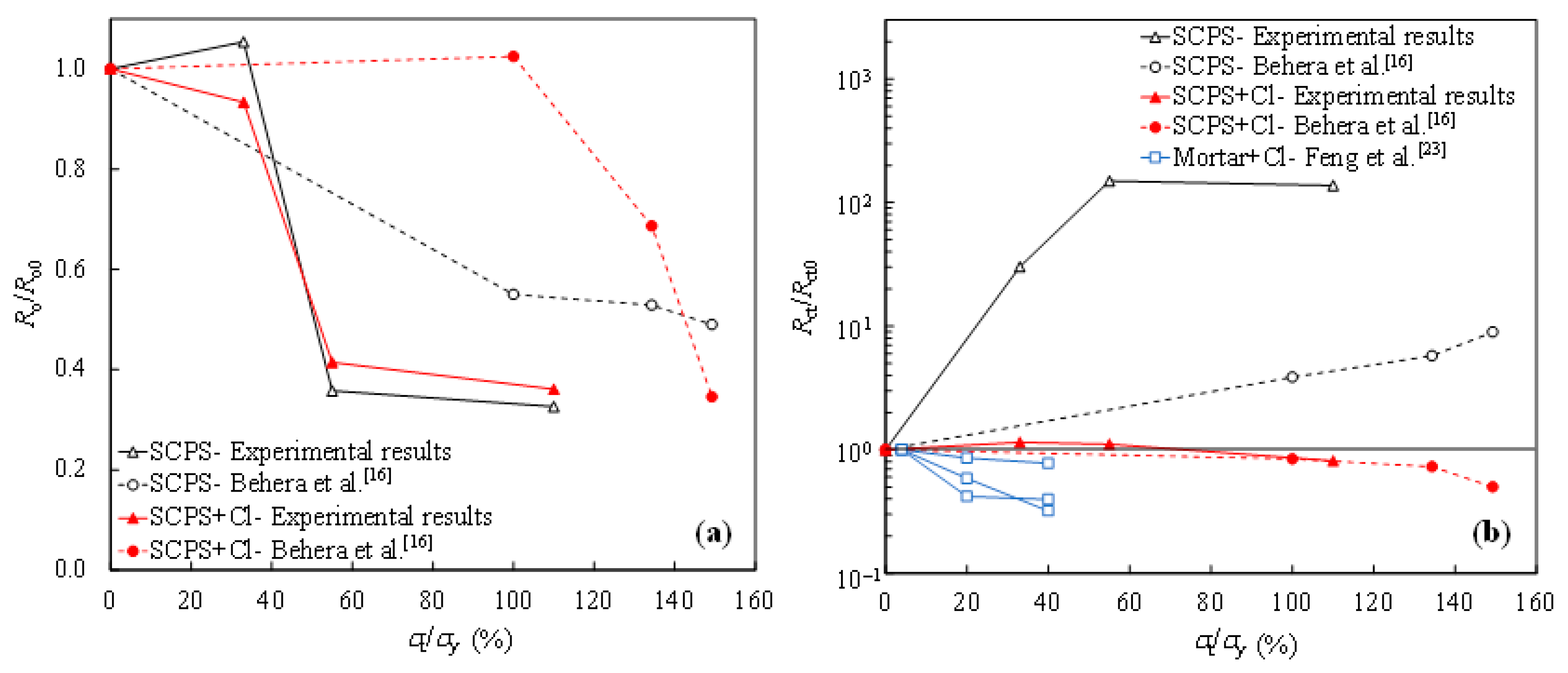
Figure 7a shows the degradation of the passive film resistance (Ro) in the concrete environment with the increasing value of tensile stress, in comparison to the results obtained by other researchers. The ratio of Ro for the tensile-stressed steel to the non-stressed Ro0 was calculated at each level of tensile stress (% of the yield strength, denoted as σt/σy). As can be seen, Ro decreases as the value of tensile stress increases, in the case of both the chloride-free and chloride-contaminated SCPSs. In terms of the charge transfer resistance of tensile-stressed steel (Rct) in the chloride-free SCPS, enhancement in Rct is observed with increasing the tensile stress, as shown in Figure 7b, where Rct0 is the charge transfer resistance of the non-stressed steel. It indicates the beneficial effect of the tensile stress on the passivation activity of steel. However, in the chloride-contaminated SCPS, the ratio of Rct/Rct0 is inversely proportional to the value of tensile stress. Tensile stress is detrimental with respect to corrosion propagation, once the depassivation occurrs. As Figure 7b shows, a higher degree of reduction in Rct of steel in the chloride-contaminated mortar specimens is exhibited, compared to that in the SCPS containing chlorides, possibly due to the influence of stress on the damage of mortar [23].
To investigate the galvanic corrosion between the tensile-stressed and non-stressed steels, EIS measurements were performed on the stressed steel in the galvanic couple after being disconnected. As can be seen in Figure 8 and Figure 9, similar Nyquist and Bode plots of the individual specimens shown in Figure 1 and Figure 2 were observed. In this regard, the equivalent circuit provided in Figure 4 was utilized to obtain the fitting results of EIS data for the disconnected stressed steel in the galvanic couple. As can be seen in Figure 10, with respect to individual steel specimens, a considerable reduction in the charge transfer resistance (Rct) was generally observed after adding 3 wt % sodium chlorides. The values in the range of 103 to 104 kΩ∙cm2 for individual passive steel dramatically reduced to 10 to 102 kΩ∙cm2, indicating the onset of depassivation. Once the stressed steel was galvanically coupled to the non-stressed steel, however, the value of Rct hardly changed after adding 3 wt % NaCl. As Figure 10 shows, in the cases of C3, C5, and C10, the values of Rct measured at the time of 38 days and 45 days were similar to the values measured before the addition of 3 wt % chlorides. In this regard, the stressed steel specimens were still in a passivation state at 38 days and 45 days. At the time of 53 days, the concentration of NaCl was increased to 10 wt %, followed by performing the EIS measurement after 24 h. A significant reduction in the value of Rct was exhibited compared to the results at the time of 45 days. It indicated that the onset of depassivation for tensile-stressed steel in the galvanic couple was delayed until a higher concentration of chloride was reached.
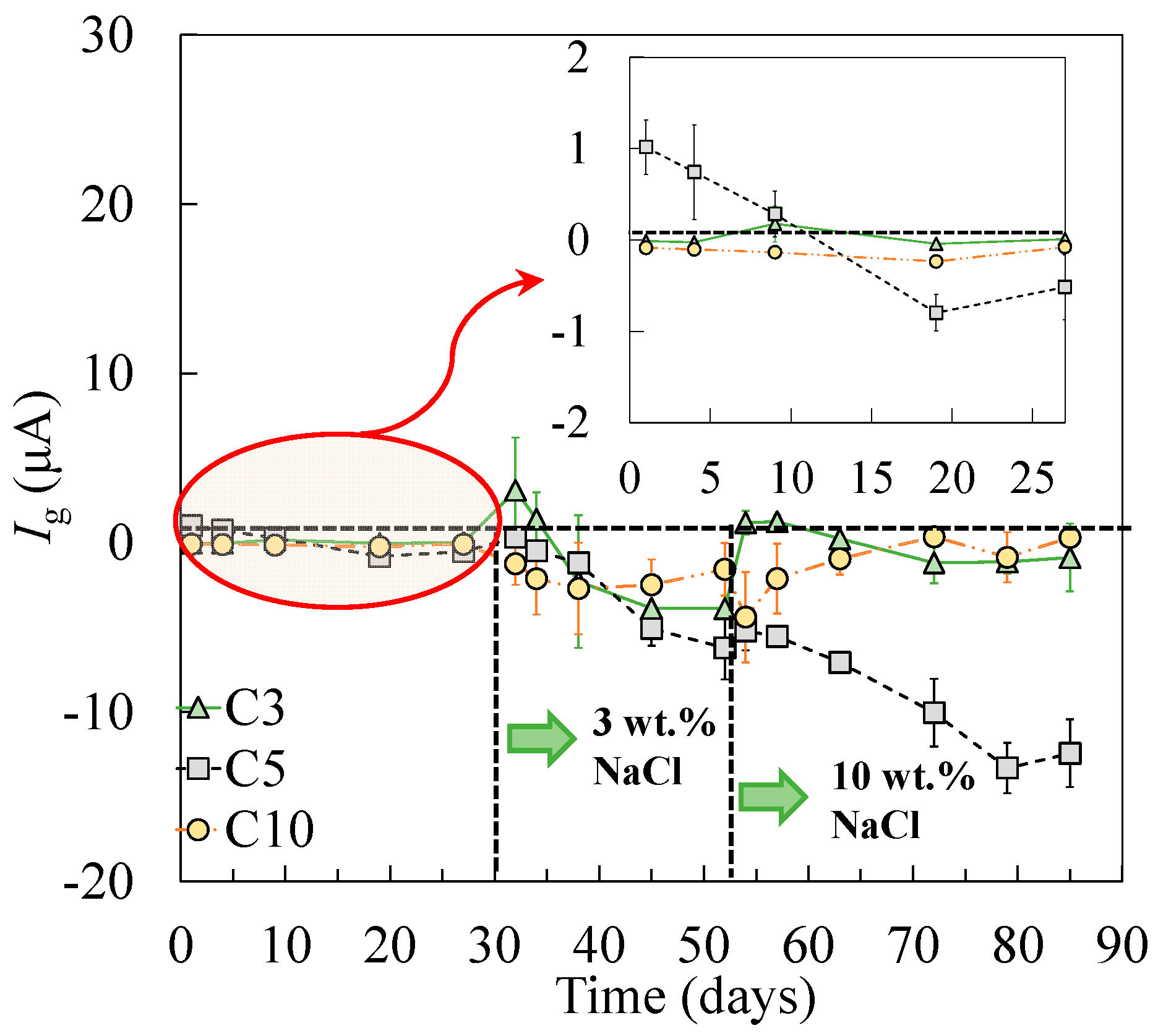
As shown in the corrosion potential of the steel specimens (Figure 6), the tensile-stressed steels demonstrated a less negative potential during passivation, compared to the non-stressed steels A0. As a result, when the stressed and non-stressed steels were galvanically coupled, the stressed steel was polarized. The critical chloride threshold value to depassivate steel, therefore, increased, which can be attributed to the cathodic prevention effect [46]. After the addition of 3 wt % chlorides, negative values of galvanic current between the stressed and non-stressed steels were measured in all cases, as shown in Figure 11. As the concentration of chlorides increased to 10 wt %, the stressed steel in the galvanic couple tended to depassivate, resulting in the change of the galvanic current, in either the absolute value or the direction of the galvanic current. According to the decreasing trend in terms of the charge transfer resistance for the stressed steel, especially the plastically stressed A10, a long-term corrosion test is necessary for the investigation of the galvanic corrosion between the stressed and non-stressed steel couples in future work.
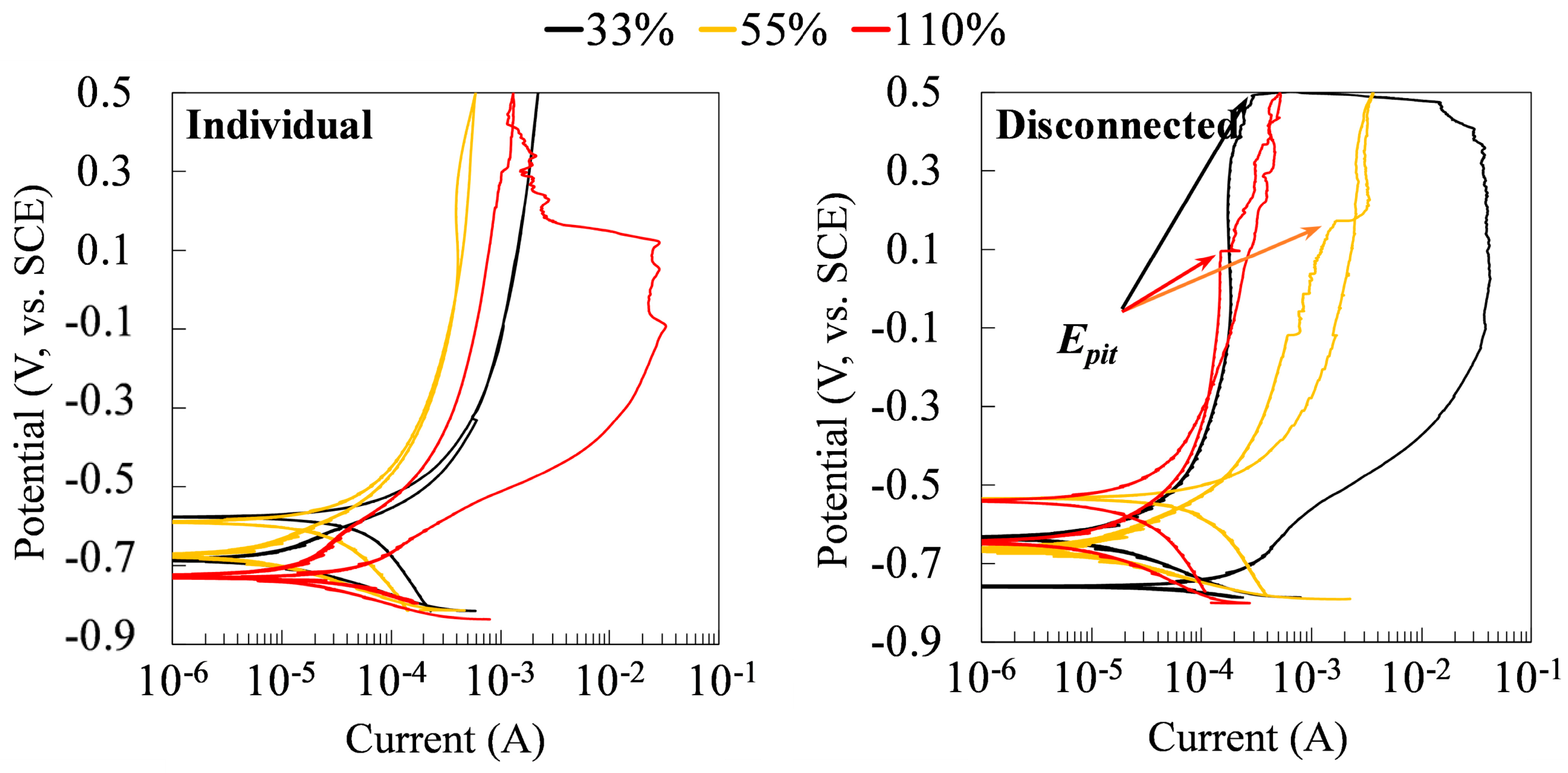
Figure 12 shows the results of the CP tests on the specimens at the time of 75 days. For the stressed steels in the galvanic couple system, the CP tests were performed on the stressed specimens after being disconnected with the non-stressed specimens for 30 min. As can be seen, while there were no pitting potentials in the cyclic polarization curves of individual specimens under different tensile stresses, all coupled specimens showed pitting potentials. It indicated the susceptibility to the pitting corrosion of the tensile-stressed steels after being galvanically coupled to the non-stressed steel. Coupling changes the corrosion behaviors of all specimens, regardless of the level of stress.

4. Conclusions

This study investigated the galvanic corrosion between tensile-stressed and non-stressed steels in an SCPS, in addition to the influence of tensile stress on the passivation and corrosion behavior of steel, through electrochemical measurements. The following conclusions can be drawn:
(1) In terms of the passivation of steel in a chloride-free SCPS, the resistance of the oxide film decreased with increasing the value of the tensile stress. Nevertheless, the tensile stress enhanced the charge transfer resistance (i.e., the oxidation-reduction process at the surface of the metal).
(2) With the addition of 3 wt % sodium chloride, the tensile-stressed steel demonstrated a higher charge transfer resistance than the non-stressed steel at the early stage. As the concentration of chloride increased to 10 wt %, however, the stressed steels yielded a similar charge transfer resistance to or an even lower charge transfer resistance than the non-stressed steel, especially for the plastically stressed steel.
(3) As the tensile-stressed steel being galvanically coupled to the non-stressed steel start from the passivation stage, the critical chloride concentration for the tensile-stressed steel (i.e., the amount of chloride to depassivate the steel) was increased in this study, indicating a cathodic prevention effect on the tensile-stressed steel. Nevertheless, there is a necessity for a long-term investigation regarding the galvanic corrosion between stressed and non-stressed steels in the future.

Author Contributions

Conceptualization, Z.D.; methodology, Z.D. and A.P.; formal analysis, Z.D. and A.P.; investigation, Z.D.; writing—original draft preparation, Z.D.; writing—review and editing, Z.D., A.P. and C.F.; supervision, A.P.; project administration, A.P. and Z.D.; funding acquisition, Z.D. All authors have read and agreed to the published version of the manuscript.

Funding

This research was financially supported by the Zhejiang Provincial Natural Science Foundation of China (grant number: LQ22E080017), as well as the Key laboratory of Performance Evolution and Control for Engineering Structures (Tongji University), Ministry of Education (No. 2021KF-2).

Institutional Review Board Statement

Not applicable.

Informed Consent Statement

Not applicable.

Data Availability Statement

Some or all data, models, or codes that support the findings of this study are available from the corresponding author upon reasonable request.

Acknowledgments

Thanks go to Corrosion Research Laboratory (CoRLab) at Clemson University.

Conflicts of Interest

The authors declare no conflict of interest.

References

  1. Dong, Z.; Gu, X.-L.; Jin, Z.-H.; Poursaee, A.; Ye, H. Experimental and numerical investigations on the rate-limiting step for macrocell corrosion of reinforcing steel in concrete. J. Mater. Civ. Eng. 2022, 34, 04021407. [Google Scholar] [CrossRef]
  2. Sabzi, M.; Jozani, A.H.; Zeidvandi, F.; Sadeghi, M.; Dezfuli, S.M. Effect of 2-mercaptobenzothiazole concentration on the sour corrosion behavior of API X60 pipeline steel: Electrochemical parameters and adsorption mechanism. Int. J. Miner. Met. Mater. 2020, 25, 288–299. [Google Scholar] [CrossRef]
  3. Golchinvafa, A.; Anijdan, S.H.M.; Sabzi, M.; Sadeghi, M. The effect of natural inhibitor concentration of Fumaria officinalis and temperature on corrosion protection mechanism in API X80 pipeline steel in 1 M H2SO4 solution. Int. J. Press. Vessel. Pip. 2020, 188, 104241. [Google Scholar] [CrossRef]
  4. Sabzi, M.; Dezfuli, S.M.; Asadian, M.; Tafi, A.; Mahaab, A. Study of the effect of temperature on corrosion behavior of galvanized steel in seawater environment by using potentiodynamic polarization and EIS methods. Mater. Res. Express 2019, 6, 076508. [Google Scholar] [CrossRef]
  5. Anijdan, S.H.M.; Arab, G.; Sabzi, M.; Sadeghi, M.; Eivani, A.R.; Jafarian, H.R. Sensitivity to hydrogen induced cracking, and corrosion performance of an API X65 pipeline steel in H2S containing environment: Influence of heat treatment and its subsequent microstructural changes. J. Mater. Res. Technol. 2021, 15, 1–16. [Google Scholar] [CrossRef]
  6. Shi, J.; Ming, J.; Sun, W.; Zhang, Y. Corrosion performance of reinforcing steel in concrete under simultaneous flexural load and chlorides attack. Constr. Build. Mater. 2017, 149, 315–326. [Google Scholar] [CrossRef]
  7. Wang, J.; Basheer, P.A.M.; Nanukuttan, S.V.; Long, A.E.; Bai, Y. Influence of service loading and the resulting micro-cracks on chloride resistance of concrete. Constr. Build. Mater. 2016, 108, 56–66. [Google Scholar] [CrossRef] [Green Version]
  8. Wang, H.L.; Dai, J.G.; Sun, X.Y. Chloride transport in concrete under sustained flexural loading. Mag. Concr. Res. 2017, 69, 245–254. [Google Scholar] [CrossRef]
  9. Li, L.; Li, C.Q.; Mahmoodian, M. Effect of applied stress on corrosion and mechanical properties of mild steel. J. Mater. Civ. Eng. 2019, 31, 04018375. [Google Scholar] [CrossRef]
  10. Zhang, Y.; Poursaee, A. Study of the semi-conductive behavior of the passive film on carbon steel in simulated concrete pore solution under stress. Anti-Corrosion Methods Mater. 2015, 62, 363–370. [Google Scholar] [CrossRef]
  11. Zhang, Y.; Poursaee, A. Passivation and corrosion behavior of carbon steel in simulated concrete pore solution under tensile and compressive stresses. J. Mater. Civ. Eng. 2015, 27, 04014234. [Google Scholar] [CrossRef]
  12. Li, F.; Yuan, Y.; Li, C.Q. Corrosion propagation of prestressing steel strands in concrete subjected to chloride attack. Constr. Build. Mater. 2011, 25, 3878–3885. [Google Scholar] [CrossRef]
  13. Ren, R.K.; Zhang, S.; Pang, X.L.; Gao, K.W. A novel observation of the interaction between the macroelastic stress and electrochemical corrosion of low carbon steel in 3.5 wt% NaCl solution. Electrochim. Acta 2012, 85, 283–294. [Google Scholar] [CrossRef]
  14. Wang, Y.; Xu, L.; Sun, J.; Cheng, Y.F. Mechano-electrochemical interaction for pipeline corrosion: A review. J. Pipeline Sci. Eng. 2021, 1, 1–16. [Google Scholar] [CrossRef]
  15. Chen, L.; Liu, W.; Dong, B.; Zhao, Y.; Zhang, T.; Fan, Y.; Yang, W. Insight into electrochemical passivation behavior and surface chemistry of 2205 duplex stainless steel: Effect of tensile elastic stress. Corros. Sci. 2021, 193, 109903. [Google Scholar] [CrossRef]
  16. Behera, P.K.; Misra, S.; Mondal, K. Corrosion behavior of strained rebar in simulated concrete pore solution. J. Mater. Eng. Perform. 2020, 29, 1939–1954. [Google Scholar] [CrossRef]
  17. Feng, X.; Tang, Y.; Zuo, Y. Influence of stress on passive behaviour of steel bars in concrete pore solution. Corros. Sci. 2011, 53, 1304–1311. [Google Scholar] [CrossRef]
  18. Song, Z.; Zhang, Y.; Liu, L.; Pu, Q.; Jiang, L.; Chu, H.; Luo, Y.; Liu, Q. Use of XPS for quantitative evaluation of tensile-stress-induced degradation of passive film on carbon steel in simulated concrete pore solution. Constr. Build. Mater. 2021, 274, 121779. [Google Scholar] [CrossRef]
  19. Feng, X.; Zuo, Y.; Tang, Y.; Zhao, X.; Lu, X. The degradation of passive film on carbon steel in concrete pore solution under compressive and tensile stresses. Electrochim. Acta 2011, 58, 258–263. [Google Scholar] [CrossRef]
  20. Cason, C.; Pezzato, L.; Breda, M.; Furlan, F.; Dabalà, M. Effect of microstructure and residual stresses, generated from different annealing and deformation processes, on the corrosion and mechanical properties of gold welding alloy wires. Gold Bull. 2015, 48, 135–145. [Google Scholar] [CrossRef] [Green Version]
  21. Poursaee, A. Corrosion of Ti–6Al–4V orthopaedic alloy under stress. Materialia 2019, 6, 100271. [Google Scholar] [CrossRef]
  22. Zhou, C.H.; Ma, H.T.; Wang, L. Comparative study of oxidation kinetics for pure nickel oxidized under tensile and compressive stress. Corros. Sci. 2010, 52, 210–215. [Google Scholar] [CrossRef]
  23. Feng, X.; Lu, X.; Zuo, Y.; Zhuang, N.; Chen, D. Electrochemical study the corrosion behaviour of carbon steel in mortars under compressive and tensile stresses. Corros. Sci. 2016, 103, 66–74. [Google Scholar] [CrossRef]
  24. Gu, X.-L.; Dong, Z.; Yuan, Q.; Zhang, W.-P. Corrosion of stirrups under different relative humidity conditions in concrete exposed to chloride environment. J. Mater. Civ. Eng. 2020, 32, 04019329. [Google Scholar] [CrossRef]
  25. Dong, Z.; Poursaee, A. Corrosion behavior of coupled active and passive reinforcing steels in simulated concrete pore solution. Constr. Build. Mater. 2020, 240, 117955. [Google Scholar] [CrossRef]
  26. Torbati-Sarraf, H.; Poursaee, A. Corrosion of coupled steels with different microstructures in concrete environment. Constr. Build. Mater. 2018, 167, 680–687. [Google Scholar] [CrossRef]
  27. Kosaba, T.; Muto, I.; Sugawara, Y. Effect of anodizing on galvanic corrosion resistance of Al coupled to Fe or type 430 stainless steel in diluted synthetic seawater. Corros. Sci. 2021, 179, 109145. [Google Scholar] [CrossRef]
  28. Policastro, S.A.; Anderson, R.M.; Hangarter, C.M. Analysis of galvanic corrosion current between an aluminum alloy and stainless-steel exposed to an equilibrated droplet electrolyte. J. Electrochem. Soc. 2021, 168, 041507. [Google Scholar] [CrossRef]
  29. Okonkwo, B.O.; Ming, H.; Wang, J.; Han, E. Galvanic corrosion study between low alloy steel A508 and 309/308 L stainless steel dissimilar metals: A case study of the effects of oxide film and exposure time. J. Nucl. Mater. 2021, 548, 152853. [Google Scholar] [CrossRef]
  30. Chen, H.; Lv, Z.; Lu, L.; Huang, Y.; Li, X. Correlation of micro-galvanic corrosion behavior with corrosion rate in the initial corrosion process of dual phase steel. J. Mater. Res. Technol. 2021, 15, 3310–3320. [Google Scholar] [CrossRef]
  31. Hao, W.; Liu, Z.; Wu, W.; Li, X.; Du, C.; Zhang, D. Electrochemical characterization and stress corrosion cracking of E690 high strength steel in wet-dry cyclic marine environments. Mater. Sci. Eng. A 2018, 710, 318–328. [Google Scholar] [CrossRef]
  32. Poursaee, A. Corrosion of steel bars in saturated Ca(OH)2 and concrete pore solution. Concrete Research Letter. 2010, 1, 90–97. [Google Scholar]
  33. Poursaee, A.; Hansson, C.M. Reinforcing steel passivation in mortar and pore solution. Cem. Concr. Res. 2007, 37, 1127–1133. [Google Scholar] [CrossRef]
  34. Dong, Z.; Torbati-Sarraf, H.; Hussein, H.Z.; Poursaee, A. Harmonic analysis on the effect of potential perturbations and electrodes arrangements on the electrochemical impedance (EIS) measurement of cementitious material. Constr. Build. Mater. 2021, 273, 121701. [Google Scholar] [CrossRef]
  35. Sabzi, M.; Far, S.M.; Dezfuli, S.M. Characterization of bioactivity behavior and corrosion responses of hydroxyapatite-ZnO nanostructured coating deposited on NiTi shape memory alloy. Ceram. Int. 2018, 44, 21395–21405. [Google Scholar] [CrossRef]
  36. Poursaee, A. Determining the appropriate scan rate to perform cyclic polarization test on the steel bars in concrete. Electrochim. Acta 2010, 55, 1200–1206. [Google Scholar] [CrossRef]
  37. Orazem, M.E.; Pébère, N.; Tribollet, B. Enhanced graphical representation of electrochemical impedance data. J. Electrochem. Soc. 2006, 153, B129–B136. [Google Scholar] [CrossRef]
  38. Torbati-Sarraf, H.; Torbati-Sarraf, S.A.; Chawla, N.; Poursaee, A. A comparative study of corrosion behavior of an additively manufactured Al-6061 RAM2 with extruded Al-6061 T6. Corros. Sci. 2020, 174, 108838. [Google Scholar] [CrossRef]
  39. Volpi, E.; Olietti, A.; Stefanoni, M.; Trasatti, S.P. Electrochemical characterization of mild steel in alkaline solutions simulating concrete environment. J. Electroanal. Chem. 2015, 736, 38–46. [Google Scholar] [CrossRef]
  40. Torbati-Sarraf, H.; Poursaee, A. The influence of phase distribution and microstructure of the carbon steel on its chloride threshold value in a simulated concrete pore solution. Constr. Build. Mater. 2020, 259, 119784. [Google Scholar] [CrossRef]
  41. Li, Y.; Cheng, Y.F. Passive film growth on carbon steel and its nanoscale features at various passivating potentials. Appl. Surf. Sci. 2017, 396, 144–153. [Google Scholar] [CrossRef]
  42. Ghods, P.; Isgor, O.B.; Bensebaa, F.; Kingston, D. Angle-resolved XPS study of carbon steel passivity and chloride-induced depassivation in simulated concrete pore solution. Corros. Sci. 2012, 58, 159–167. [Google Scholar] [CrossRef]
  43. Chakri, S.; Frateur, I.; Orazem, M.E.; Sutter, E.M.M.; Tran, T.T.M.; Tribollet, B.; Vivier, V. Improved EIS analysis of the electrochemical behaviour of carbon steel in alkaline solution. Electrochim. Acta 2017, 246, 924–930. [Google Scholar] [CrossRef]
  44. Cattarin, S.; Comisso, N.; Musiani, M.; Tribollet, B. The impedance of an electrode coated by a resistive film with a graded thickness. Electrochem. Solid-State Lett. 2008, 11, C27–C30. [Google Scholar] [CrossRef]
  45. Cattarin, S.; Comisso, N.; Musiani, M.; Tribollet, B. Electrodes coated by passive oxide films with a thickness profile: Modeling and measurement of the impedance response. J. Electrochem. Soc. 2008, 155, C543–C549. [Google Scholar] [CrossRef]
  46. Sagüés, A.A.; Sánchez, A.N.; Lau, K.; Kranc, S.C. Service life forecasting for reinforced concrete incorporating potential-dependent chloride threshold. Corrosion 2014, 70, 942–957. [Google Scholar] [CrossRef] [Green Version]
Figure 1. Schematic illustration of the C-shape carbon steel.
Metals 12 00098 g001
Figure 2. Nyquist plots of individual specimens subjected to different levels of tensile stress. Symbol: experimental results. Line: fitting results.
Metals 12 00098 g002
Figure 3. Adjusted Bode plots of individual specimens: (a) A0; (b) A3; (c) A5; (d) A10.
Metals 12 00098 g003
Figure 4. The equivalent circuit used to simulate the behavior of steel in the concrete pore solution.
Metals 12 00098 g004
Figure 5. Resistance of oxide film (a) and charge transfer (b) of steel specimens at various stress levels.
Metals 12 00098 g005
Figure 6. Corrosion potentials of steels subjected to different levels of tensile stress.
Metals 12 00098 g006
Figure 7. Ratio of the resistance under tensile-stressed conditions to non-stressed condition with respect to the oxide film (Ro/Ro0) (a) and the charge transfer (Rct/Rct0) (b) of the steel specimens.
Metals 12 00098 g007
Figure 8. Nyquist plots of the stressed specimens when coupled to the non-stressed steel. Symbol: experimental results. Line: fitting results.
Metals 12 00098 g008
Figure 9. Adjusted Bode plots of the tensile-stressed specimens in coupled cells: (a) C3; (b) C5; (c) C10.
Metals 12 00098 g009
Figure 10. Resistances of individual and coupled steel specimens subjected to 33% of σy (a), 55% of σy (b), and 110% of σy (c).
Metals 12 00098 g010
Figure 11. The galvanic current between the stressed and non-stressed steels.
Metals 12 00098 g011
Figure 12. Cyclic polarization curves of the individual and disconnected stressed specimens in a galvanic couple at 75 days of exposure to the chloride-contaminated SCPS.
Metals 12 00098 g012
Table 1. Displacements for the length of the rod (H) and the corresponding stress levels.
Specimens Nos. Reduction in HH; mm)Tensile Stress (MPa)Percentage of Yield Stress (%)
Individual CellCoupled Cell
A0C00.000.000
A3C33.00125.5233
A5C55.00209.2055
A10C1010.00418.40110
Table 2. Chemical compositions of the C-shape carbon steel specimen.
Element Percentage (%)
C0.100–0.200
Mn0.300–0.400
P<0.035
S<0.035
Table 3. Chemical compositions and pH of the simulated concrete pore solution.
CompoundConcentration (mol/L)
NaOH0.1
KOH0.3
Ca(OH)20.03
CaSO4⋅H2O (gypsum)0.002
pH13.1
Publisher’s Note: MDPI stays neutral with regard to jurisdictional claims in published maps and institutional affiliations.