Article

Microstructure and Mechanical Properties of the ((CoCrFeNi)95Nb5)100−xMox High-Entropy Alloy Coating Fabricated under Different Laser Power

1
School of Mechanical Engineering, University of Science and Technology Beijing, Beijing 100083, China
2
China Nuclear Power Technology Research Institute Co., Ltd., Reactor Engineering and Safety Research Center, Shenzhen 518031, China
3
Beijing Instrument Industry Research Institute Co., Ltd., Beijing 101176, China
*
Authors to whom correspondence should be addressed.
Metals 2021, 11(9), 1477; https://doi.org/10.3390/met11091477
Submission received: 7 August 2021 / Revised: 9 September 2021 / Accepted: 11 September 2021 / Published: 17 September 2021

Abstract

:
In this paper, the ((CoCrFeNi)95Nb5)100−xMox (x = 1, 1.5 and 2) high-entropy alloy (HEA) coatings were fabricated on the substrate of 45# steel by laser cladding process under different laser beam power. The influence of laser beam power and molybdenum element content on the microstructure and microhardness of the HEA coatings was investigated. Results show that the HEA coatings were composed of face-centered cubic (FCC) phase and Laves phase, had low porosity, and bonded well to the substrate. The Mo1 coating is composed of cellular dendritic structures and columnar dendritic structures. With the increase of molybdenum element content, the columnar dendritic structures disappeared, the grains are refined, and the arrangement of grains is more compact. The volume fraction of the interdendritic phase under the laser beam power of 800 W was small and irregular. After the laser beam power was increased to 1000 W, the volume fraction of the interdendritic phase was increased. Under the laser beam power of 1200 W, the volume fraction of the interdendritic phase was small again. Therefore, the coatings fabricated under the laser beam power of 1000 W had a larger volume fraction of the interdendritic phase and higher microhardness. With the increase in molybdenum content, the grain changed from columnar dendrite to cellular dendrite, and the microhardness of the coating increased. The characteristics of the laser cladding process, the formation of Laves phase, and the fine grain strengthening lead to high microhardness of the coatings.

1. Introduction

Unlike conventional alloys which have only one or two principal elements as a substrate, high-entropy alloys (HEAs) consist of at least four principal elements and tend to form a simple solid solution phase, such as body-centered cubic (BCC) phase, face-centered cubic (FCC) phase, or hexagonal close-packed (HCP) phase [1,2,3,4]. With the careful addition of elements, HEAs can show many excellent properties, such as superior corrosion resistance, excellent magnetic properties, high strength, and high microhardness. Among them, the CoCrFeNi system HEAs, which exhibit remarkable corrosion resistance, exceptional ductility and fracture toughness, have been the focus of attention [5,6,7,8,9,10].
Up to now, most of the bulk HEAs have been prepared by casting. However, cost severely limits casting size, and high density (~8 g/cm3) limits the bulk HEAs’ engineering application. A reasonable way to solve this problem is to develop HEA coatings on the substrate of conventional materials. At present, the most widely used methods to prepare HEA coatings are laser metal deposition, mechanical alloying, plasma spraying, and laser cladding [11,12,13].
With the characteristics of fast curing speed (104~106 °C·s−1), little thermal effect on the substrate, and excellent metallurgical bonding, the laser cladding technology shows great application potential in the preparation of HEA coatings [14,15,16]. According to the ways of adding raw materials, laser cladding processes can be divided into two types: synchronous laser cladding process and pre-placed laser cladding process. Figure 1 shows the equipment for the synchronous laser cladding process. In the process of synchronous laser cladding, the raw material is directly blown into the laser action zone, and it shortens the pretreatment process and has little requirement on the surface morphology of the substrate [17,18,19,20]. Therefore, the synchronous laser cladding process was selected to fabricate the ((CoCrFeNi)95Nb5)100−xMox HEA coatings.
In order to obtain a coating with excellent performance, it is necessary to design a reasonable element composition and select appropriate process parameters. In order to explore the effects of different elements on the performance of HEAs, several studies have been carried out [21,22,23]. For instance, He et al. designed the CoCrFeNiNbx HEAs with excellent mechanical properties by adding Nb element into CoCrFeNi substrate [24]. Yang et al. studied the microstructure and mechanical properties of the CoCrFeNiMox HEAs. The CoCrFeNiMo0.8 HEA they designed showed good wear resistance and strength [25].
In addition, many scholars have found that the laser cladding process parameters also have important influence on the performance of coatings [26,27,28,29,30]. The research of Weng et al. shows that the microhardness and wear resistance of the Co-based composite coatings on Ti-6Al-4V titanium alloy were enhanced with the decrease in laser-specific energy [31]. The T15M composite coatings on the Q235 steel substrate were fabricated by Jiao et al. under different laser scanning speed. Results indicated that the coating fabricated under the scanning speed of 200 mm/min had better wear resistance [32].
In our previous study, the (CoCrFeNi)95Nb5 HEA coating was successfully fabricated on the substrate of Q235 steel by plasma spraying technology, which shows high microhardness and good corrosion resistance [33]. Moreover, the influence of Mo content on corrosion resistance and microstructure of the (CoCrFeNi)100−xMox HEA was investigated [34]. In this study, we integrated previous studies, the ((CoCrFeNi)95Nb5)100−xMox (x = 1, 1.5, and 2, represented by Mo1, Mo1.5, and Mo2, respectively) HEA coatings on the substrate of 45# steel were successfully fabricated by laser cladding process. And the effects of molybdenum content and laser beam power on the microstructure and mechanical properties of the HEA coatings were analyzed.

2. Material and Methods

2.1. Powder Preparation

The main chemical composition of the 45# steel substrate was Fe (base), Ni (<0.30%), P (<0.035%), Mn (0.5~0.8%), C (0.42~0.50%), and Si (0.17~0.37). The preparation method of the CoCrFeNi95Nb5 powder was the same as previous research [33]. Planetary ball milling system (DECO-PBM-V-2/4/6L-A, DECO, Changsha, China) was used to mix the HEA powder and Mo powder according to mass ratio.

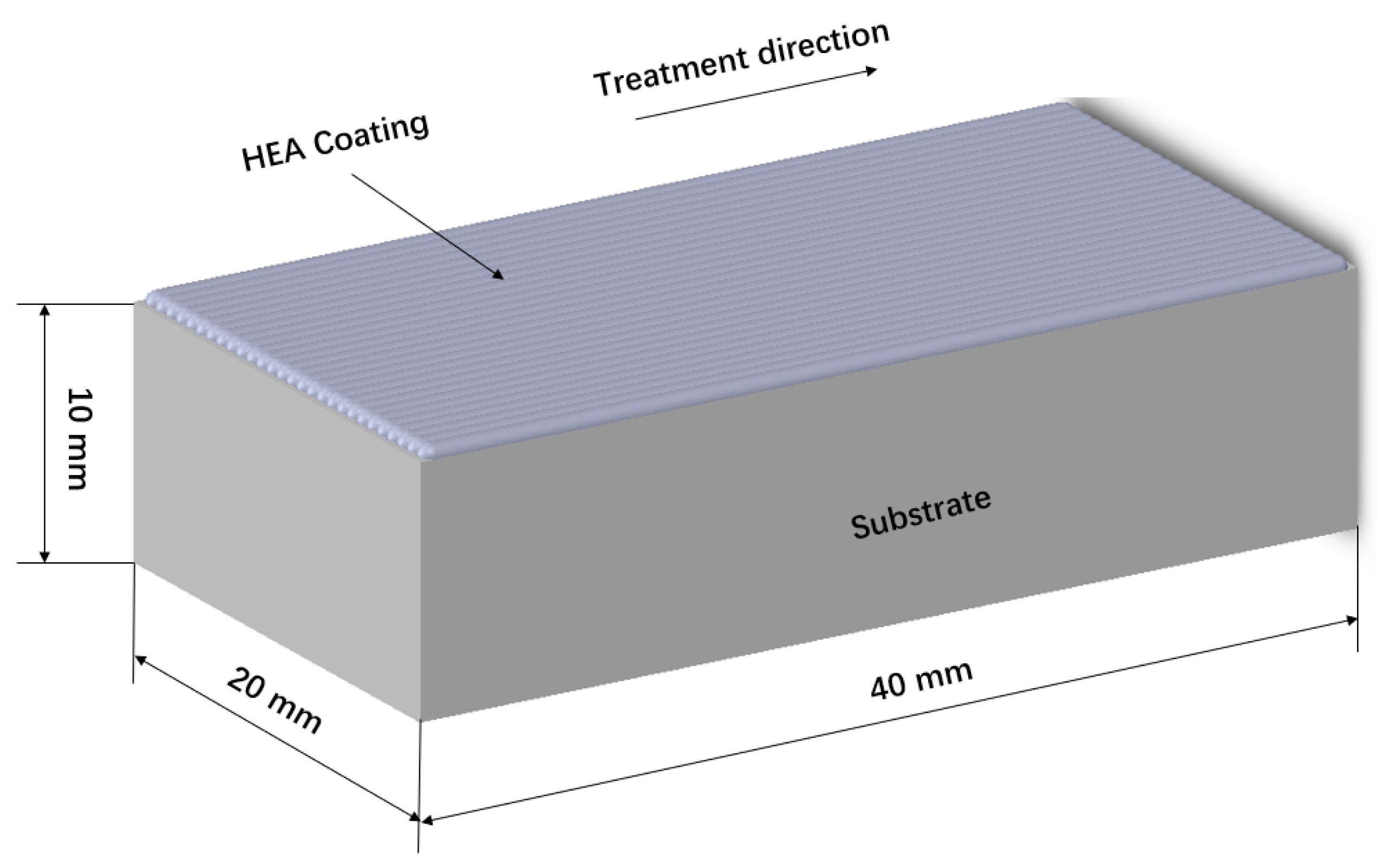
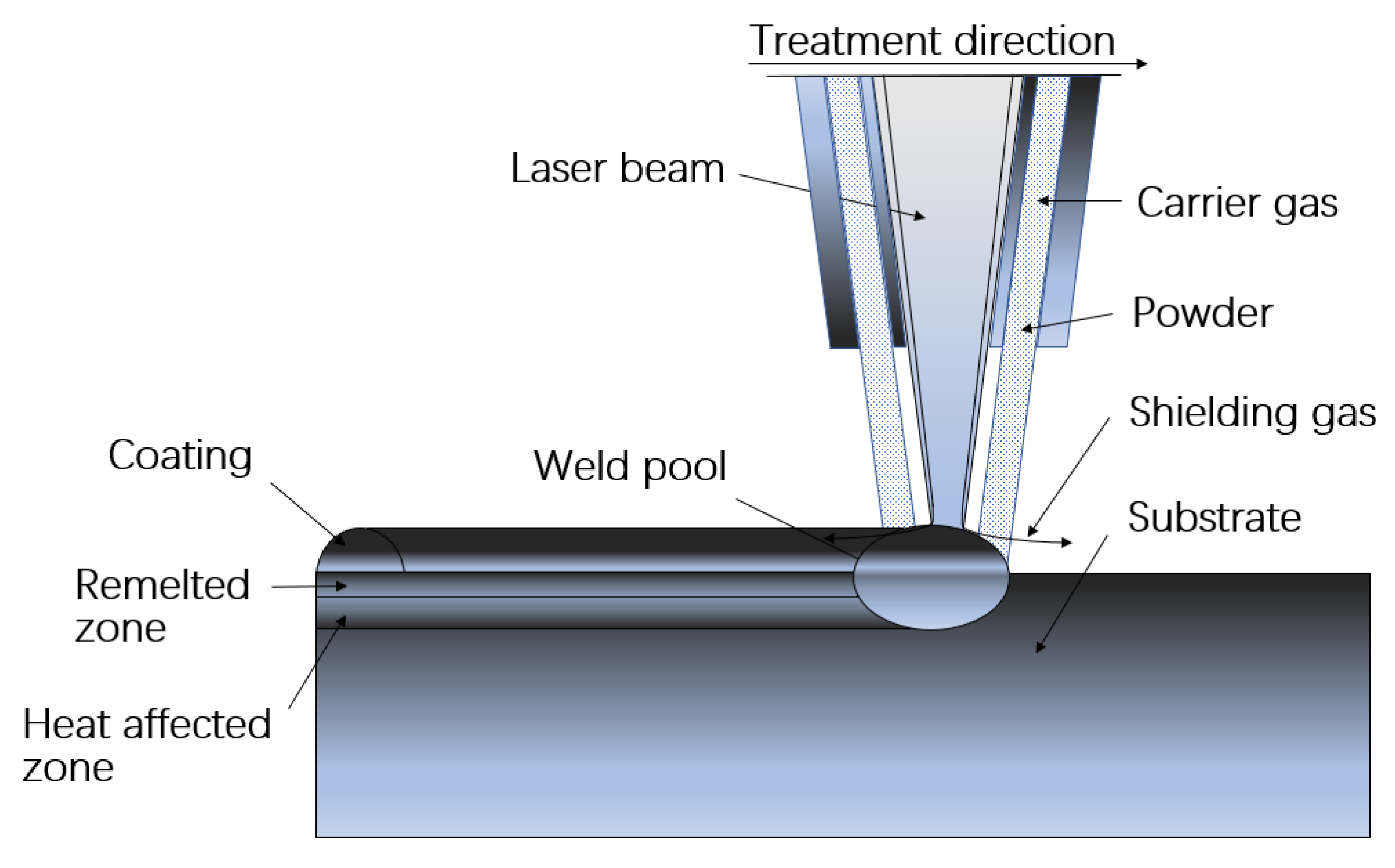
2.2. Coatings Preparation

Using the ((CoCrFeNi)95Nb5)100−xMox HEA powder as the raw material, the HEA coatings were prepared by laser cladding system (LDF3000-60, Laserline, Mülheim-Kärlich, Germany). And the laser beam power was 800~1200 Ww, the powder feeding rate was 2 L/min, the spot diameter was 2 mm, and scanning speed was 4 mm/s. HEA coatings were produced in 16 passes. After each working movement (each track), the laser head returned to initial position and shifted by 1 mm. The lapping rate was 25% in lap coating, and the entire cladding process was protected by argon gas blown sideways. Other parameters of the laser cladding process associated with power laser beam, its power density, and its scanning speed are shown in Table 1. Solid work model of a specimen with coating is shown in Figure 2, whereas schematic diagram of the laser cladding process is shown in Figure 3.

2.3. Coating Characterization

X-ray diffractometer (XRD, Rigaku D/MAX-RB, Rigaku Corporation, Tokyo, Japan) was used to identify the crystal structures of the HEA coatings with the Cu Kα radiation operated at 30 kV. The scanning range was 20°~100° and the scanning rate was 10°/min. The microstructure and chemical composition of the HEA coatings were analyzed by field emission scanning electron microscope (FSEM, Nova Nano SEM450, FEI, Hillsboro, OR, USA) coupled with energy dispersive spectrometry (EDS).

2.4. Microhardness Measurements

The microhardness of the HEA coatings, with a load of 500 g and a load time of 15 s, was measured by microhardness tester (MICROMET-6030, Buehler, Plymouth, MN, USA). Each sample was measured 10 times, and the average value after removing the maximum value and the minimum value was taken.

3. Results and Discussion

3.1. Microstructure of the ((CoCrFeNi)95Nb5)100−xMox Powder

Figure 4a represents the XRD patterns of the ((CoCrFeNi)95Nb5)100−xMox HEA powder. Results show that the ((CoCrFeNi)95Nb5)100−xMox HEA powder exhibits FCC phase and molybdenum element phase. Our previous research has shown that the (CoCrFeNi)95Nb5 HEA powder exhibits a single FCC solid solution structure and, with the increase in molybdenum element content, the diffraction peaks of molybdenum element appear and increase [33]. The microstructure of the ((CoCrFeNi)95Nb5)100−xMox HEA powder are shown in Figure 4b–d. The powder particles of the three components are approximately spherical with a diameter of 80–100 μm. The surface of these powder particles is not smooth and a large number of satellite spheres are attached.

3.2. The Effect of Mo Element Content on the Microstructure of the HEA Coating

To study the influence of molybdenum element content on the microstructure of the HEA coatings, the Mo1, Mo1.5, and Mo2 HEA coatings were fabricated by laser cladding process under the laser beam power of 800 W. The thickness of the coatings is about 2 mm. Figure 5a represents the XRD patterns of these coatings. Results show that, compared with the powder, there is no diffraction peaks of the molybdenum element, which indicates that the molybdenum element had a solid solution with other elements in the system. The FCC phase is the main phase of the HEA coatings, and the strength of the FCC phase diffraction peaks changes with the increase in molybdenum element content, which may be caused by the preferential orientation. A new phase can be found in the HEA coatings and the strength of the new phase diffraction peaks has no obvious change when the molybdenum element content changes, which can indicate that the formation of the new phase is not caused by the addition of molybdenum element. Combined with previous studies, the new phase can be identified as the Laves phase, and the generation of this phase is related to the addition of Nb element [33].
The microstructure of the ((CoCrFeNi)95Nb5)100−xMox HEA coatings with laser beam power of 800 W is shown in Figure 5b–d. The coatings prepared by the HEA powder are composed of typical dendritic structure. The white contrast (marked as DR in the figure) is dendrites, and the darker contrast (marked as ID in the figure) is interdendrites. The Mo1 coating is composed of cellular dendritic structures and columnar dendritic structures [34]. With the increase in molybdenum element content, the columnar dendritic structures disappear, the grains are refined, and the arrangement of grains is more compact [35].
The chemical composition results analyzed by EDS of the dendritic phase and interdendritic phase of the HEA coatings are shown in Table 2. Results show that the Nb element content in the interdendritic phase is higher than the designed value. Similar to the Nb element, the molybdenum element also shows enrichment in the interdendritic phase, while Co, Cr, Fe, and Ni are mainly enriched in the dendritic region. In addition, it can be found that, with the increase in molybdenum element content, the degree of element segregation of the interdendritic phase decreases.
The melting points of each element in the coatings are as follows: Co (1495 °C), Cr (1857 °C), Fe (1583 °C), Ni (1455 °C), Nb (2468 °C), Mo (2617 °C). Among them, the melting points of Nb and Mo elements are higher than other elements and close to each other, which makes them crystallize before other elements in the condensation process, and then segregation is formed in the interdendritic region [33]. By comparing the experimental data of the three HEA coatings, it can be found that the Mo element can refine grains, induce nucleation, and lighten the segregation of elements [36].

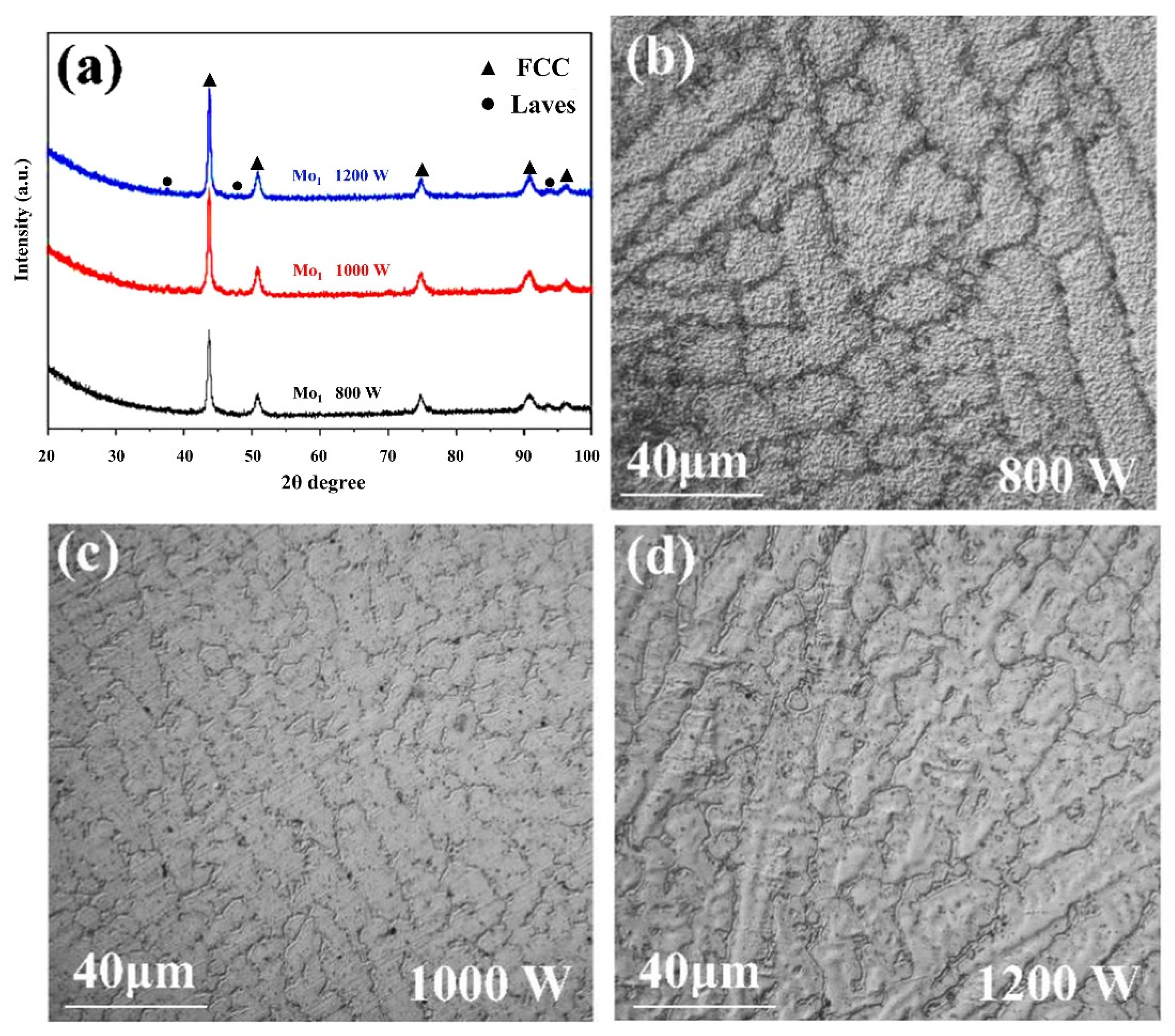
3.3. The Effect of Laser Beam Power on the Microstructure of the HEA Coating

To study the influence of laser beam power on the microstructure of the coatings, the Mo1 coatings were fabricated by laser cladding process under different laser power. The thickness of coatings was about 2 mm. Figure 6a represents the XRD patterns of the HEA coatings. Results show that, the HEA coatings were also composed of FCC phase and Laves phase. When the laser beam power changed, the strength of the two phases’ diffraction peaks did not change significantly. This indicates that the change of laser beam power has little effect on the phase formation of the HEA coatings.
Figure 6b–d show the microstructure of HEA coatings fabricated under the laser beam power of 800 W, 1000 W, and 1200 W, respectively. The grain size of the coating fabricated under the laser beam power of 800 W is coarse and irregular. After the laser beam power is increased to 1000 W, the grain size is refined. Under the laser beam power of 1200 W, the grain size becomes coarse again. The reason for this may be that the laser beam power determines the instantaneous energy input into the molten pool, and the appropriate increase in laser beam power can promote the non-spontaneous nucleation of the coating elements, so as to achieve the refinement of the microstructure [37]. However, low laser beam power leads to low energy of the molten pool and insufficient energy absorbed by the HEA powder, which is not conducive to nucleation. In addition, a further increase in laser beam power may lead to high input energy, slow cooling rate of molten pool, prolonged grain growth time, and finally, larger grain size [38,39].
Table 3 shows the chemical composition results analyzed by EDS for the dendritic phase and interdendritic phase of the HEA coatings.
The results show that the condition of element segregation is not changed with the change of laser beam power, which means that laser beam power has little relation with element segregation. Yet, when the laser beam power increases, the Fe element content in the coatings increases. This is because a higher laser beam power makes the molten pool energy rise, which then improves the melting degree of the substrate elements and the coating elements. Elements in the substrate, such as Fe, are mixed into the coatings, which increases the dilution rate and Fe element content of the coatings.

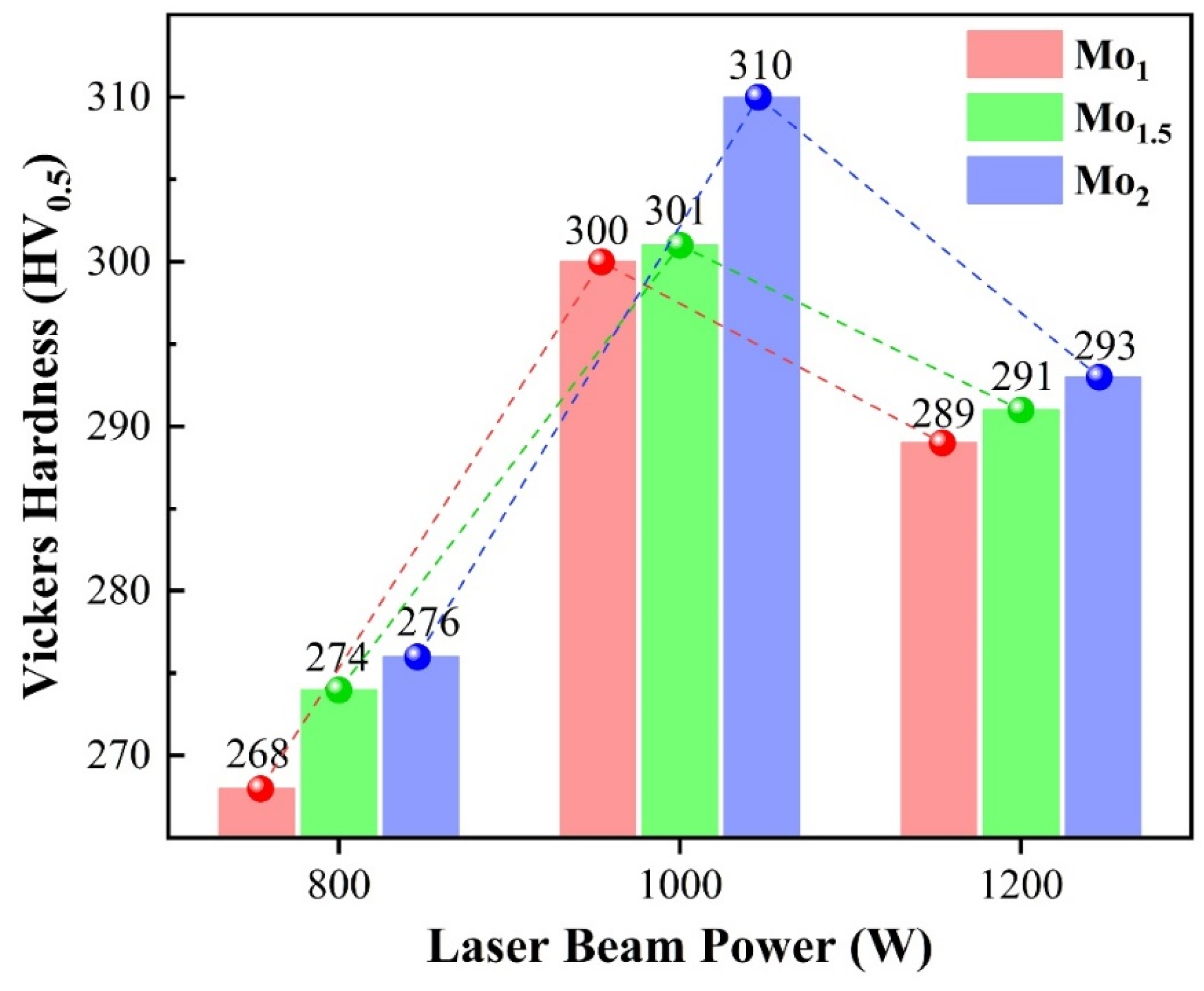
3.4. Mechanical Properties of the ((CoCrFeNi)95Nb5)100−xMox HEA Coating

To understand the bond type of the coating and the substrate. The thickness of the coatings is about 2 mm. The SEM image of the longitudinal section of the Mo1 HEA coating fabricated under the laser power of 800 W was analyzed, and result is shown in Figure 7a The SEM image shows that only a few pores can be found in the coating, which means the coating has a low porosity. In addition, no obvious stratified gap is found at the interface which indicates that the coating is well combined with the substrate.
A narrow transition region between the coating and the 45# steel substrate can be found by observing the SEM image. To prove it, EDS line scanning was performed on the longitudinal section of the coating. Result is shown in Figure 7b; the content of Co, Cr, Fe, and Ni elements in the coating is basically stable, while the content of Nb and Mo elements in the coating fluctuates, and their fluctuations are positively correlated. There is a relatively obvious transition area of diffusion between the coating and the substrate, with a width of about 2 μm. This indicates that the coating is bonded to the substrate in a metallurgical manner, which means that the coating has a high bonding strength with the substrate.
Figure 8 shows the microhardness of these coatings, which was detected by the microhardness tester. Results show that the microhardness of the HEA coatings is much higher than that of the substrate (125 HV0.5). One reason for this is that the laser cladding process is accompanied by the rapid melting and solidification of materials. At the time of solidification, a large degree of undercooling is produced, and the nucleation rate of the material becomes faster, which makes the growth time of each dendrite shorter and makes the coating’s microstructure fine. Another reason is the formation of the Laves phase in the HEA coatings. The Laves phase is a hard phase, so the formation of the Laves phase also leads to the increase in the microhardness of the HEA coatings.
In addition, it can be found that the microhardness of the HEA coatings is affected by laser beam power and molybdenum content, and the major influence is the laser beam power. Combined with Figure 8, it can be found that the influence of laser beam power and molybdenum content on the microstructures of the HEA coatings is the key to determine the microhardness. Among the HEA coatings, the microhardness of Mo2 coating prepared under 1000 W laser beam power was the highest, which was 310 HV0.5. An observable phenomenon is that the coatings with high molybdenum content prepared under the laser beam power of 1000 W have higher microhardness. The main reason for this result may be that these HEA coatings have smaller grain size, which leads to increased grain boundary and fine grain strengthening, so that the microhardness of the coatings increased.
When the laser power increases from 1000 W to 1200 W, the melting time of the HEA powder which can be calculated by Equation (1) becomes shorter. Therefore, during the cooling process, the cooling rate of the molten pool, which can be calculated by Equation (2), slows down and the dendrite coarsening time is prolonged. The relationship between the dendrite arm spacing d and dendrite coarsening time t c is shown in Equation (3). When the dendrite coarsening time is prolonged, the dendrite arm spacing becomes wider, which will lead to the grain size becoming larger, the fine grain strengthening effect being weakened, and the dilution rate of the coating increased, resulting in the decrease in the microhardness. Besides, due to the insufficient energy absorbed by the HEA powder, nucleation is limited, resulting in lower microhardness of the HEA coatings prepared under low laser beam power.
Δ t = R p 2 ( L m / C p ) κ ( T a T m )
where Δt is the melting time of the HEA powder (s),   R p is the HEA powder diameter (m), T a is the temperature of the molten pool (K), T m is the melting temperature of the HEA powder (K), κ is a constant, C p is the specific heat capacity of the HEA powder (J/kg·K), and L m is the latent heart of the HEA powder (J/kg).
v c = 4 π λ T s 2 v s / P
where, T s is the temperature at the test point S (K), v s is the laser scanning speed (mm/s), λ is the thermal conductivity (W/(m·K)), and P is the laser beam power (W).
d = a ( Γ D l n ( C 1 C 0 ) t c m ( 1 k ) ( C 1 C 0 ) ) 1 3
where, a is a constant, Γ is the Gibbs–Thompson coefficient, D is the coefficient of solute diffusion (m2/s), C 1 is the solute concentration in liquid alloy (%), C 0 is the original solute concentration in the liquid alloy (%), m is the slope of the liquidus, and k is the equilibrium partition coefficient.

4. Conclusions

(1)
Results show that the HEA coatings consist of FCC phase and Laves phase. The porosity of the HEA coatings is low and the HEA coatings are combined with the substrate in a metallurgical way.
(2)
The HEA coatings exhibit a typical dendritic structure and the interdendritic phase enriches with Nb and Mo, which may be caused by the different melting points of the elements and the characteristics of the laser cladding process.
(3)
The grain size of the coating fabricated under the laser beam power of 800 W is coarse and irregular. After the laser beam power is increased to 1000 W, the grain size is refined. Under the laser beam power of 1200 W, the grain size becomes coarse again. The reason for this may be that the laser beam power determines the instantaneous energy input into the molten pool, and an appropriate increase in laser beam power can promote the non-spontaneous nucleation of the coating elements, so as to achieve the refinement of the microstructure. However, low laser beam power leads to low energy of the molten pool and insufficient energy absorbed by the HEA powder, which is not conducive to nucleation. In addition, a further increase in laser beam power may lead to high input energy, slow cooling rate of molten pool, prolonged grain growth time, and finally, larger grain size.
(4)
The microstructure of the coatings changed from a columnar dendritic structure to a cellular dendritic structure with the increase in molybdenum element content, the grain size was refined, and the degree of element segregation of the interdendritic phase decreased. The microhardness of the HEA coatings is much higher than that of the 45# steel substrate and greatly affected by laser beam power. With the increase in molybdenum element content, the microhardness of the HEA coatings also increased. The characteristics of the laser cladding process, the formation of Laves phase, and the fine grain strengthening lead to the high microhardness of the coatings.

Author Contributions

Investigation, writing—original draft, Q.S.; supervision, visualization, writing—review & editing, W.W. and W.Q.; investigation, J.H., D.L. and D.W.; supervision, W.W.; supervision, conceptualization, writing-review & editing, L.X. All authors have read and agreed to the published version of the manuscript.

Funding

This work was supported by the National Key R&D Program of China (Grant No. 2020YFA0405700) and the Fundamental Research Funds for the Central Universities (Grant No. FRF-MP-20-31).

Institutional Review Board Statement

Not applicable.

Informed Consent Statement

No. 2020YFA0405700) and the Fundamental Research Funds for the Central Universities (Grant No. FRF-MP-20-31).

Data Availability Statement

All the data generated during this study are included in this article.

Conflicts of Interest

The authors declare no conflict of interest.

References

  1. Yeh, J.W.; Chen, S.K.; Lin, S.J.; Gan, J.Y.; Chin, T.S.; Shun, T.T.; Tsau, C.H.; Chang, S.Y. Nanostructured high-entropy alloys with multiple principal elements: Novel alloy design concepts and outcomes. Adv. Eng. Mater. 2004, 6, 299. [Google Scholar] [CrossRef]
  2. Liu, W.H.; Yang, T.; Liu, C.T. Precipitation hardening in CoCrFeNi-based high entropy alloys. Mater. Chem. Phys. 2018, 210, 2. [Google Scholar] [CrossRef]
  3. Sathiyamoorthi, P.; Basu, J.; Kashyap, S.; Pradeep, K.G.; Kottada, R.S. Thermal stability and grain boundary strengthening in ultrafine-grained CoCrFeNi high entropy alloy composite. Mater. Des. 2017, 134, 426. [Google Scholar] [CrossRef]
  4. Hou, J.; Fan, J.; Yang, H.; Wang, Z.; Qiao, J. Deformation Behavior and Plastic Instabilities of Boronized Al0.25 CoCrFeNi High-Entropy Alloys. Int. J. Miner. Metall. Mater. 2020, 27, 1363–1370. [Google Scholar] [CrossRef]
  5. Cantor, B.; Chang, I.T.H.; Knight, P.; Vincent, A.J.B. Microstructural development in equiatomic multicomponent alloys. Mater. Sci. Eng. A 2004, 375–377, 213. [Google Scholar] [CrossRef]
  6. Salishchev, G.A.; Tikhonovsky, M.A.; Shaysultanov, D.G.; Stepanov, N.D.; Kuznetsov, A.V.; Kolodiy, I.V.; Tortika, A.S.; Senkov, O.N. Effect of Mn and V on structure and mechanical properties of high-entropy alloys based on CoCrFeNi system. J. Alloys Compd. 2014, 591, 11. [Google Scholar] [CrossRef]
  7. He, F.; Wang, Z.; Wu, Q.; Li, J.; Wang, J.; Liu, C.T. Phase separation of metastable CoCrFeNi high entropy alloy at intermediate temperatures. Scr. Mater. 2017, 126, 15. [Google Scholar] [CrossRef] [Green Version]
  8. Praveen, S.; Basu, J.; Kashyap, S.; Kottada, R.S. Exceptional resistance to grain growth in nanocrystalline CoCrFeNi high entropy alloy at high homologous temperature. J. Alloys Compd. 2016, 662, 361. [Google Scholar] [CrossRef]
  9. Vaidya, M.; Trubel, S.; Murty, B.S.; Wilde, G.; Divinski, S.V. Ni tracer diffusion in CoCrFeNi and CoCrFeMnNi high entropy alloys. J. Alloys Compd. 2016, 688, 994. [Google Scholar] [CrossRef]
  10. Zhang, A.; Han, J.; Su, B.; Li, P.; Meng, J. Microstructure, mechanical properties and tribological performance of CoCrFeNi high entropy alloy matrix self-lubricating composite. Mater. Des. 2017, 114, 253. [Google Scholar] [CrossRef]
  11. Shang, C.; Axinte, E.; Sun, J.; Li, X.; Li, P.; Du, J.; Qiao, P.; Wang, Y. CoCrFeNi(W1−xMox) high-entropy alloy coatings with excellent mechanical properties and corrosion resistance prepared by mechanical alloying and hot pressing sintering. Mater. Des. 2017, 117, 193. [Google Scholar] [CrossRef]
  12. Chao, Q.; Guo, T.; Jarvis, T.; Wu, X.; Hodgson, P.; Fabijanic, D. Direct laser deposition cladding of AlxCoCrFeNi high entropy alloys on a high-temperature stainless steel. Surf. Coat. Technol. 2017, 332, 440. [Google Scholar] [CrossRef]
  13. Jiang, Y.Q.; Li, J.; Juan, Y.F.; Lu, Z.J.; Jia, W.L. Evolution in microstructure and corrosion behavior of AlCoCrxFeNi high-entropy alloy coatings fabricated by laser cladding. J. Alloys Compd. 2019, 775, 1. [Google Scholar] [CrossRef]
  14. Zhang, Y.; Han, T.; Xiao, M.; Shen, Y. Effect of process parameters on the microstructure and properties of laser-clad FeNiCoCrTi 0.5 high-entropy alloy coating. Int. J. Miner. Metall. Mater. 2020, 27, 630–639. [Google Scholar] [CrossRef]
  15. Zhang, S.; Wu, C.L.; Yi, J.Z.; Zhang, C.H. Synthesis and characterization of FeCoCrAlCu high-entropy alloy coating by laser surface alloying. Surf. Coat. Technol. 2015, 262, 64. [Google Scholar] [CrossRef]
  16. Zhang, H.; He, Y.-Z.; Pan, Y.; Guo, S. Thermally stable laser cladded CoCrCuFeNi high-entropy alloy coating with low stacking fault energy. J. Alloys Compd. 2014, 600, 210. [Google Scholar] [CrossRef]
  17. He, X.; Kong, D.; Song, R. Microstructures and Properties of Laser Cladding Al-TiC-CeO2 Composite Coatings. Materials 2018, 11, 198. [Google Scholar] [CrossRef] [Green Version]
  18. Ni, C.; Shi, Y.; Liu, J.; Huang, G. Characterization of Al0.5FeCu0.7NiCoCr high-entropy alloy coating on aluminum alloy by laser cladding. Opt. Laser Technol. 2018, 105, 257. [Google Scholar] [CrossRef]
  19. Jiang, H.; Han, K.; Li, D.; Cao, Z. Synthesis and Characterization of AlCoCrFeNiNbx High-Entropy Alloy Coatings by Laser Cladding. Crystals 2019, 9, 56. [Google Scholar] [CrossRef] [Green Version]
  20. Zhang, H.; Pan, Y.; He, Y.-Z. Synthesis and characterization of FeCoNiCrCu high-entropy alloy coating by laser cladding. Mater. Des. 2011, 32, 1910. [Google Scholar] [CrossRef]
  21. Tong, C.-J.; Chen, Y.-L.; Yeh, J.-W.; Lin, S.-J.; Chen, S.-K.; Shun, T.-T.; Tsau, C.-H.; Chang, S.-Y. Microstructure characterization of Alx CoCrCuFeNi high-entropy alloy system with multiprincipal elements. Metall. Mater. Trans. A 2005, 36, 881. [Google Scholar] [CrossRef]
  22. Li, B.S.; Wang, Y.P.; Ren, M.X.; Yang, C.; Fu, H.Z. Effects of Mn, Ti and V on the microstructure and properties of AlCrFeCoNiCu high entropy alloy. Mater. Sci. Eng. A 2008, 498, 482. [Google Scholar] [CrossRef]
  23. Tian, F.; Delczeg, L.; Chen, N.; Varga, L.K.; Shen, J.; Vitos, L. Structural stability of NiCoFeCrAlx high-entropy alloy from ab initio theory. Phys. Rev. B 2013, 88, 085128. [Google Scholar] [CrossRef]
  24. He, F.; Wang, Z.; Cheng, P.; Wang, Q.; Li, J.; Dang, Y.; Wang, J.; Liu, C.T. Designing eutectic high entropy alloys of CoCrFeNiNbx. J. Alloys Compd. 2016, 656, 284. [Google Scholar] [CrossRef]
  25. Yang, Q.; Tang, Y.; Wen, Y.; Zhang, Q.; Deng, D.; Nai, X. Microstructures and properties of CoCrCuFeNiMox high-entropy alloys fabricated by mechanical alloying and spark plasma sintering. Powder Metall. 2018, 61, 115. [Google Scholar] [CrossRef]
  26. Riquelme, A.; Rodrigo, P.; Escalera-Rodríguez, M.D.; Rams, J. Analysis and optimization of process parameters in Al–SiCp laser cladding. Opt. Lasers Eng. 2016, 78, 165. [Google Scholar] [CrossRef]
  27. Weng, F.; Chen, C.; Yu, H. Research status of laser cladding on titanium and its alloys: A review. Mater. Des. 2014, 58, 412. [Google Scholar] [CrossRef]
  28. Ocelík, V.; de Oliveira, U.; de Boer, M.; de Hosson, J.T.M. Thick Co-based coating on cast iron by side laser cladding: Analysis of processing conditions and coating properties. Surf. Coat. Technol. 2007, 201, 5875. [Google Scholar] [CrossRef] [Green Version]
  29. Yang, J.; Liu, F.; Miao, X.; Yang, F. Influence of laser cladding process on the magnetic properties of WC–FeNiCr metal–matrix composite coatings. J. Mater. Process. Technol. 2012, 212, 1862. [Google Scholar] [CrossRef]
  30. Muvvala, G.; Karmakar, D.P.; Nath, A.K. Online monitoring of thermo-cycles and its correlation with microstructure in laser cladding of nickel based super alloy. Opt. Lasers Eng. 2017, 88, 139. [Google Scholar] [CrossRef]
  31. Weng, F.; Yu, H.; Chen, C.; Liu, J.; Zhao, L.; Dai, J.; Zhao, Z. Effect of process parameters on the microstructure evolution and wear property of the laser cladding coatings on Ti-6Al-4V alloy. J. Alloys Compd. 2017, 692, 989. [Google Scholar] [CrossRef]
  32. Jiao, X.; Wang, J.; Wang, C.; Gong, Z.; Pang, X.; Xiong, S.M. Effect of laser scanning speed on microstructure and wear properties of T15M cladding coating fabricated by laser cladding technology. Opt. Lasers Eng. 2018, 110, 163. [Google Scholar] [CrossRef]
  33. Wang, W.; Qi, W.; Xie, L.; Yang, X.; Li, J.; Zhang, Y. Microstructure and Corrosion Behavior of (CoCrFeNi)95Nb5 High-Entropy Alloy Coating Fabricated by Plasma Spraying. Materials 2019, 12, 694. [Google Scholar] [CrossRef] [Green Version]
  34. Wang, W.; Wang, J.; Sun, Z.; Li, J.; Li, L.; Song, X.; Wen, X.; Xie, L.; Yang, X. Effect of Mo and aging temperature on corrosion behavior of (CoCrFeNi)100−xMox high-entropy alloys. J. Alloys Compd. 2020, 812, 152139. [Google Scholar] [CrossRef]
  35. Dai, C.-D.; Zhao, T.-L.; Du, C.-W.; Liu, Z.-Y.; Zhang, D.-W. Effect of molybdenum content on the microstructure and corrosion behavior of FeCoCrNiMox high-entropy alloys. J. Mater. Sci. Technol. 2020, 46, 64–73. [Google Scholar] [CrossRef]
  36. Xia, Y.-L. Microstructure and Properties of Fecocroni-MX High Entropy Alloy Coating by Laser Murder; Jinan University: Guangzhou, China, 2016. [Google Scholar]
  37. Lin, J.-X.; Niu, L.-Y.; Li, G.-Y.; Cao, H.-G.; Cao, Y.-L. Effects of laser power on the dilution rate and corrosion resistance of laser-clad coated CO based alloy coating of ball valve. Process 2014, 43, 112. [Google Scholar]
  38. Yang, D.; Ning, Y.-H.; Zhao, Y.-G.; Zhu, G.-B.; Xu, X.-F. Effect of Process Parameters on Tissue, Wear Resistance and Corrosion Resistance of Laser Cladding Ni - based Alloy Coatings of 304 Stainless Steel. Midament 2017, 31, 133. [Google Scholar]
  39. Ma, B.-B.; Hu, L.-W.; Liu, X.; Li, J.-F.; Zhang, J.; Le, G.-L.; Li, X.-Y. Influence of Laser Power on Microstructure and Properties of Fe-Si-B Laser Clay Coating. J. Mater. Heat Treat. 2018, 39, 113. [Google Scholar]
Figure 1. Synchronous laser cladding equipment.
Metals 11 01477 g001
Figure 2. Solid work model of specimen with coating.
Metals 11 01477 g002
Figure 3. Schematic diagram of the laser cladding process.
Metals 11 01477 g003
Figure 4. (a) XRD patterns of the ((CoCrFeNi)95Nb5)100−xMox (x = 1, 1.5, 2) HEA powder; (bd) SEM images of the ((CoCrFeNi)95Nb5)100−xMox (x = 1, 1.5, 2) HEA powder, where (b) x = 1, (c) x = 1.5, (d) x = 2.
Metals 11 01477 g004
Figure 5. (a) XRD patterns of the ((CoCrFeNi)95Nb5)100−xMox (x = 1, 1.5, 2) HEA coatings, (bd) SEM images of the ((CoCrFeNi)95Nb5)100−xMox (x = 1, 1.5, 2) HEA coatings.
Metals 11 01477 g005
Figure 6. (a) XRD patterns of the ((CoCrFeNi)95Nb5)99Mo1 HEA coatings prepared under different laser beam power, (bd) SEM images of the((CoCrFeNi)95Nb5)99Mo1 HEA coatings prepared under different laser beam power.
Metals 11 01477 g006
Figure 7. (a) SEM image of longitudinal section of the ((CoCrFeNi)95Nb5)99Mo1 coating prepared under the laser beam power of 800 W, (b) distributions of alloying elements by EDS line scanning.
Metals 11 01477 g007aMetals 11 01477 g007b
Figure 8. Microhardness of the ((CoCrFeNi)95Nb5)100−xMox (x = 1, 1.5, 2) HEA coating.
Metals 11 01477 g008
Table 1. Laser cladding parameters.
SpecimenLaser Beam Parameters
Powder Feeding Rate (L/min)Spot Diameter (mm)Scanning Speed (mm/s)Exposure Time of Laser Beam on Material (s)Laser Beam Fluence (J/mm)Laser Beam Power Density (W/mm2)
Laser beam powerPowder mixture composition
800 WMo12240.5127255
Mo1.52240.5127255
Mo22240.5127255
Powder mixture compositionLaser beam power
Mo1800 W2240.5127255
1000 W2240.5159318
1200 W2240.5191382
Table 2. Chemical composition of the ((CoCrFeNi)95Nb5)100−xMox (x = 1, 1.5, 2) HEA coating prepared under the laser beam power of 800 W (at.%).
ElementAreaCoCrFeNiNbMo
Mo1Interdendrite19.1820.2219.9219.1120.341.23
Dendrite22.9724.1325.8724.562.420.05
Mo1.5Interdendrite22.0520.1320.9820.8214.131.89
Dendrite22.1322.9527.1224.093.020.69
Mo2Interdendrite22.1321.1424.5620.049.792.34
Dendrite23.3222.8729.2922.871.020.63
Table 3. Chemical composition of the ((CoCrFeNi)95Nb5)99Mo1 HEA coatings prepared under different laser beam power (at.%).
ElementAreaCoCrFeNiNbMo
800 WInterdendrite19.1820.2219.9219.1120.341.23
Dendrite22.9724.1325.8724.562.420.05
1000 WInterdendrite22.3718.3219.1820.1318.421.58
Dendrite22.5624.0827.3822.832.520.63
1200 WInterdendrite20.2419.0123.2219.3617.230.94
Dendrite21.3720.2934.8221.421.730.37
Publisher’s Note: MDPI stays neutral with regard to jurisdictional claims in published maps and institutional affiliations.

